EP4361394A2 - Zwei-leiter-system für erdbohrgestängeschüsse - Google Patents
Zwei-leiter-system für erdbohrgestängeschüsse Download PDFInfo
- Publication number
- EP4361394A2 EP4361394A2 EP23205246.4A EP23205246A EP4361394A2 EP 4361394 A2 EP4361394 A2 EP 4361394A2 EP 23205246 A EP23205246 A EP 23205246A EP 4361394 A2 EP4361394 A2 EP 4361394A2
- Authority
- EP
- European Patent Office
- Prior art keywords
- conductor
- drilling rod
- earth drilling
- composite
- insulation
- Prior art date
- Legal status (The legal status is an assumption and is not a legal conclusion. Google has not performed a legal analysis and makes no representation as to the accuracy of the status listed.)
- Granted
Links
Images


Classifications
-
- E—FIXED CONSTRUCTIONS
- E21—EARTH OR ROCK DRILLING; MINING
- E21B—EARTH OR ROCK DRILLING; OBTAINING OIL, GAS, WATER, SOLUBLE OR MELTABLE MATERIALS OR A SLURRY OF MINERALS FROM WELLS
- E21B17/00—Drilling rods or pipes; Flexible drill strings; Kellies; Drill collars; Sucker rods; Cables; Casings; Tubings
- E21B17/02—Couplings; joints
- E21B17/028—Electrical or electro-magnetic connections
- E21B17/0285—Electrical or electro-magnetic connections characterised by electrically insulating elements
-
- E—FIXED CONSTRUCTIONS
- E21—EARTH OR ROCK DRILLING; MINING
- E21B—EARTH OR ROCK DRILLING; OBTAINING OIL, GAS, WATER, SOLUBLE OR MELTABLE MATERIALS OR A SLURRY OF MINERALS FROM WELLS
- E21B17/00—Drilling rods or pipes; Flexible drill strings; Kellies; Drill collars; Sucker rods; Cables; Casings; Tubings
- E21B17/02—Couplings; joints
- E21B17/028—Electrical or electro-magnetic connections
-
- E—FIXED CONSTRUCTIONS
- E21—EARTH OR ROCK DRILLING; MINING
- E21B—EARTH OR ROCK DRILLING; OBTAINING OIL, GAS, WATER, SOLUBLE OR MELTABLE MATERIALS OR A SLURRY OF MINERALS FROM WELLS
- E21B47/00—Survey of boreholes or wells
- E21B47/12—Means for transmitting measuring-signals or control signals from the well to the surface, or from the surface to the well, e.g. for logging while drilling
- E21B47/13—Means for transmitting measuring-signals or control signals from the well to the surface, or from the surface to the well, e.g. for logging while drilling by electromagnetic energy, e.g. radio frequency
Definitions
- the invention relates to a two-wire system for earth drilling rod sections for forming a drill string for an earth drilling device, an earth drilling rod section with a two-wire system, an earth drilling rod section system and a use in transmitting electrical signals and/or electrical current with a two-wire system for earth drilling rod sections for forming a drill string for an earth drilling device.
- a drill head When drilling in the ground using a rod-based earth drilling device, particularly for creating so-called horizontal bores, a drill head is usually driven by a drill string from a drive device arranged on the earth's surface or in an excavation pit.
- the drill strings used can have individual, interconnected earth drilling rod sections, which - depending on the drilling process - are gradually attached to the rear end of the already drilled drill string and connected to it.
- a disadvantage of the conductors in the earth drilling rod sections, which have otherwise functioned well up to now, can arise from a possible short circuit, especially if a drilling fluid is used when drilling or creating the earth bore and more than one conductor is provided in the earth drilling rod section.
- the invention was based on the object of creating a two-wire system for earth drilling rod sections for forming a drill string for an earth drilling device, an earth drilling rod section with a two-wire system, an earth drilling rod section system and a use in transmitting electrical signals and/or electrical current with a two-wire system for earth drilling rod sections for forming a drill string for an earth drilling device, with which the connection of the earth drilling rod sections can be formed and released as easily as possible, in particular without the occurrence of a short circuit.
- a first core idea of the invention is to create insulation for a two-wire system, which provides a better insulation effect of the multiple conductors among themselves or from each other, while also maintaining the handling of the earth drilling rod sections, in particular when forming and also when separating the connection of the earth drilling rod sections.
- the invention follows the initially unrealistic approach of not only providing one insulation sleeve around one of the conductors, but also providing two insulation sleeves around the same conductor, which in particular have a different longitudinal extension along one or two conductors.
- the first core idea of the invention can support patentability on its own.
- the invention provides a two-conductor system for earth drilling rod sections for forming a drill string for an earth drilling device, wherein the two-conductor system has an insulated composite of a first conductor and a second conductor, and the first and the second conductors are each exposed at one end of the composite in a connection direction. At least a portion of an exposed end of one of the conductors is circumferentially surrounded by an inner and an outer insulation sleeve. This can provide effective insulation of the one conductor.
- two-wire system in the sense of the invention describes a system that can be arranged in a drilling rod section, which in turn is designed to form a drill string for a drilling device.
- the two-wire system can have a length that is adapted to the drilling rod section in which it is to be arranged.
- the two-wire system can be fixed in the drilling rod section at each end.
- the two-wire system can be fixed in the drilling rod section essentially in the middle of the drilling rod section.
- the fixation in the end area of the two-wire system in the earth drilling rod section can preferably be carried out via centering stars.
- a two-wire system described here can be used to "upgrade" an existing earth drilling rod section, so that a system in the form of a two-wire system can be arranged in the earth drilling rod section, by means of which several, i.e. here at least two, conductors can be used to transmit power and/or signals over at least a section of the drill string.
- the user of a rod-based earth drilling device can be offered added value by means of the two-wire system, for example that units in the area of the drill head of the drill string can be supplied with power and/or signals.
- the provision of more than one conductor offers the user an added value that should not be underestimated, since the two conductors can be used independently of one another and are not restricted in terms of their use for future tasks and/or units arranged on the drill head.
- conductor in the sense of the description includes an electrically conductive conductor.
- two-conductor in the sense of the description includes a system in which at least two conductors are present. It can also be provided that exactly two conductors are present in the two-conductor system.
- ground drilling rod section in the sense of the description includes individual, in particular rigid rod sections that can be connected to one another directly or indirectly and that can be connected to one another in the longitudinal axial direction to form a drill rod or a drill string.
- the rod sections can be plugged or screwed together to connect to one another with the mechanical interposition of an intermediate element or without the interposition of an intermediate element. Mixed forms of plugging and screwing together the ground drilling rod sections are possible.
- the connection of the ground drilling rod sections can in particular be carried out by screwing or plugging together one end of one ground drilling rod section with another end of another ground drilling rod section.
- the term "drill string" in the sense of the description includes several interconnected earth drilling rod sections.
- the drill string can extend in the longitudinal axial direction along the longitudinal axis of the earth drilling rod sections in a drill string axis that is essentially congruent or coincides with the longitudinal axes of the earth drilling rod sections.
- the drill string can have a drill head at one end, in particular at the front, and optionally an existing drill head tip that can be designed as a drilling tool (for example as an expander head) or an area adjacent to the drill head that in particular has the same orientation as the drill head.
- the drill string can have a sensor section or a sensor housing in the region of the drill head or an area adjacent to the drill head, in which one or more sensors can be arranged.
- earth drilling device in the sense of the description includes a (and thus any) device which can move in particular a drill string comprising earth drilling rod sections in an existing or to be created channel in the ground in order to create or widen a bore, in particular a horizontal bore (HD), or to pull pipelines or other long bodies into the ground.
- the earth drilling device can in particular be an HD device.
- An earth drilling device can be a device that drives a drill string and can in particular work by displacing soil.
- the drill string can be introduced into the ground in a translatory and/or rotary manner in the longitudinal axial direction of the drill string.
- the drill string can be moved in the ground by means of the earth drilling device by applying tension or pressure.
- soil in the sense of the description includes any type of material, in particular earth, sand, rock, stone and/or stone, in which existing or to be created, preferably at least partially horizontal, channels or boreholes can be introduced.
- An underground arrangement of the soil is preferred, but not absolutely necessary.
- insulated composite includes a first conductor and a second conductor that can be handled together.
- the first conductor and the second conductor can be handled together as one element or in one piece.
- the term “insulated” expresses that the two conductors are in a composite in such a way that there is insulation from the outside.
- the first and second conductors are surrounded by insulation that is arranged circumferentially around the first and/or the second conductor.
- connection direction in the sense of the description includes a direction which expresses that a connection is present in the longitudinal axial direction of the two-wire system, which leads away from the two-wire system or the first and/or second conductor in the longitudinal axial direction of the two-wire system.
- connection direction points out of the end(s) of the earth drilling rod section.
- One of the conductors can be surrounded by both the inner and the outer insulation sleeve at least in sections. In one section both the inner and the outer insulation sleeve surround one conductor. It can be provided that one of the insulation sleeves, in particular the outer insulation sleeve, projects beyond the other insulation sleeve, in particular the inner insulation sleeve.
- An overhang in the longitudinal axial direction can be in a direction away from the two-conductor system and/or in the direction of the two-conductor system.
- one of the two insulation sleeves in particular the outer insulation sleeve, encompasses the other insulation sleeve, in particular the inner insulation sleeve, in particular in a clamp-like manner, relative to the longitudinal axis of the insulation sleeve(s) or of the two-conductor system.
- One of the insulation sleeves, in particular the outer insulation sleeve can have a length that is at least 1.5 times, in particular at least 2 times, longer than the other insulation sleeve.
- the invention follows the core idea, which in itself is already patent-justifying, of providing a design in which at least one section of an electrical conduction path is designed differently than in the prior art. There is a section designed in the direction of the two-conductor system, which adjoins the exposed end of one of the conductors.
- an electrical conduction path which has at least one section that is led from an exposed end of one conductor of the two-conductor system in a direction that is directed away from the adjacent end of the two-conductor system back towards the two-conductor system.
- the electrical conduction path by means of which the exposed end of one conductor can be directly or indirectly connected to a conductor of another two-conductor system, has a section that lies between the exposed end of one conductor and a conductor of another two-conductor system. The section leads away from the exposed end and the end of the two-conductor system adjacent to the exposed end, in the opposite direction when viewed in the longitudinal axial direction.
- the electrical conduction path can have a "backward" portion that has a section that is led back over a section of the conductor whose exposed end is in electrical contact with the electrical conduction path.
- the invention provides a two-conductor system for earth drilling rod sections for forming a drill string for an earth drilling device, in which the two-conductor system has an insulated composite of a first conductor and a second conductor. The first and the second conductor are each exposed at one end of the composite in a connection direction. An electrical conduction path is formed for at least one of the conductors, which extends from the exposed end of one conductor over the insulation of one conductor and/or the composite against the connection direction and from there leads insulated past the end of one conductor in the connection direction.
- the two aspects of the two-wire system can be easily combined. There is no difficulty in providing an inner and an outer insulation sleeve together with the electrical conduction path described. The two aspects can complement each other.
- the term “exposed” in the sense of the description includes the design that access to the conductor is possible, particularly in the radial direction or at its circumference.
- the term “exposed” therefore includes the design that there is no insulation on the circumference in the exposed area or end of the conductor.
- electrical conduction path in the sense of the description includes the formation of an electrically conductive section or path along which a current or a signal can be conducted.
- the electrical conduction path of the at least one conductor or the electrical conduction path for the at least one conductor from its exposed end can be selected such that a section of the conduction path is formed by means of insulation of the one conductor and/or the composite at a distance from the one conductor, which is formed “next to", “above” or “below” the conductor with respect to a radial direction of the conductor. With respect to the connection direction, a section of the electrical conduction path will be formed which is directed opposite to the connection direction.
- the assembly comprises a coaxial cable and the two conductors are the inner and outer conductors of the coaxial cable. This makes it possible to achieve a particularly simple design of a component of the two-conductor system. Coaxial cables are easy to handle and use.
- the exposed end of one conductor is contacted by means of an electrically conductive ring resting on the exposed end, by means of which the insulation of one conductor and/or the composite is sealed by pressing an insulating sealing piece onto the insulation of one conductor and/or the composite.
- the aforementioned design makes it possible to achieve a simple type of contacting, but also to ensure the integrity of the composite and/or the insulation of the conductor to the greatest possible extent.
- the ring can be used not only to provide part of the electrical conduction path, but also to maintain the integrity of the insulated composite even in the presence of pressurized drilling fluid.
- the drilling fluid could get "under” the insulation of one conductor or the composite in the area of the exposed end of the conductor and the insulation could become permanently detached.
- a synergistic effect can be achieved in that the electrically conductive ring can cause both the electrical formation of the electrical conduction path and the integrity of the insulation of one conductor or the composite.
- the ring can be screwed over or into a counterpart which surrounds the insulation of one conductor and/or the composite adjacent to the outer surface of the composite.
- the insulating sealing piece can be pressed together with the ring with an axial directional component onto the insulation of one conductor and/or the composite when screwing. This makes it possible to create a connection that is simply designed, easy to construct and plan, and which may only require screwing the ring and the counterpart together.
- a front portion of the ring is surrounded by an insulating sleeve, in particular the outer insulating sleeve, in the connection direction.
- an insulating sleeve in particular the outer insulating sleeve, shields the ring in a direction that corresponds to the connection direction and is commonly referred to as "towards the front" (away from the two-conductor system), in order to maintain a "distance" between the conductors or the formed electrical conduction path from one conductor to the other conductor or its exposed end.
- the insulation sleeve can be one of several elements that support the effect or formation of the "backward-directed" electrical conduction path.
- an electrically conductive connecting sleeve surrounds an insulating sleeve, in particular at least partially the outer insulating sleeve, and extends at least partially over the ring and/or the counterpart.
- a section of the electrical conduction path provided in the connection direction can be created by means of the electrically conductive connecting sleeve, which leads into the rear/back area (into the central area of the two-conductor system) into which the electrical conduction path is initially formed from the exposed end of one conductor.
- the electrical conduction path that was initially led backwards from the exposed end, i.e. against the connection direction, can be led forwards again, i.e. in the connection direction, by means of the connecting sleeve.
- the electrically conductive connecting sleeve provides an element that is easy to handle, construct and use. In addition, a simple plug connection can be used. The connecting sleeve can be pushed over the ring and/or the counterpart of the ring.
- the two-wire system for earth drilling rod sections for forming a drill string for an earth drilling device comprises a pressure relief valve for discharging excess pressure from the area of the two-wire system.
- a pressure relief valve for discharging excess pressure from the area of the two-wire system.
- pressure relief valve for relieving excess pressure refers to any valve that can respond or open when the pressure in the range of Two-wire system rises above a set pressure.
- the set pressure can essentially be understood as the pressure that corresponds to the pressure above the pressure of the environment outside the drill string. It is understood that due to the sealing effect to be ensured in the pressure relief valve, which requires a restoring or pre-stressed effect between the closure or shut-off body and the sealing surface or valve seat, the overpressure at which the pressure relief valve responds can be slightly higher than the ambient pressure.
- area of the two-wire system means an area intended for the connection of a first and/or a second electrical conductor of the two-wire system to a corresponding first and/or second electrical conductor of the two-wire system.
- the invention also provides an earth drilling rod section with a two-wire system.
- the two-wire system is arranged, in particular by means of at least one centering star, in the earth drilling rod section essentially centrally in a cavity extending along the longitudinal axis of the earth drilling rod section.
- the earth drilling rod sections can be prefabricated with the described two-wire system.
- the arrangement by means of at least one centering star, whereby a centering star can be provided at each end of the earth drilling rod section, also allows simple maintenance and/or simple replacement in the event of wear.
- the invention also provides an earth drilling rod section system with a plurality of earth drilling rod sections having a two-wire system, wherein the earth drilling rod sections can be connected to one another to form a section of a drill string.
- At least one or more pressure relief valves can be provided on at least one end, preferably on exactly one end, of at least one earth drilling rod section or preferably on all earth drilling rod sections of the earth drilling rod system.
- the pressure relief valve(s) can be designed and arranged in such a way as to prevent an overpressure compared to the ambient pressure of the drill string in the cavity of the earth drilling rod section or in the area of the two-wire system.
- At least one pressure relief valve at one end of the earth drilling rod section can be sufficient to discharge an overpressure when two earth drilling rod sections are connected. In particular, the overpressure that can arise when two earth drilling rod sections are connected to one another can be discharged.
- the pressure relief valve can be designed as one or more closable opening(s) in a drilling rod section, which closes the cavity in which the two-wire system is arranged, with the surroundings of the drill string.
- the openings can be designed as closable through-openings from the area of the two-wire system intended for the connection or the cavity to the outside.
- An earth drilling rod section can have at least one channel in its wall to form a pressure relief valve, which can have any design with regard to its direction and cross-sectional shape. Several channels can also be provided to form a pressure relief valve.
- a straight design of a channel can be advantageous for simple production.
- a straight design transverse to the longitudinal axis of the earth drilling rod section can be preferred in order to enable the channel to be as short as possible and/or to simplify production and/or to achieve the least possible weakening of the integrity of the earth drilling rod section.
- a curved and/or straight design of the channel at any angle to the longitudinal axis of the earth drilling rod section is not excluded.
- a round, in particular circular, cross-sectional shape of the channel can simplify production, since the channel can be created as a bore, for example.
- a design other than a round cross-sectional shape is not excluded, in particular a design of the cross-sectional shape that is straight at least in sections is possible.
- the opening or the channel has a closure that acts in a direction counter to an excess pressure in the cavity or the area of the two-wire system (closing), which can be designed in the shape of a flap, for example.
- the opening or the channel can have an elastic or movable flap-shaped closure that can at least partially rest against the opening or the channel wall and be pre-tensioned against the opening or the channel wall. If the pressure in the cavity or in the area of the two-wire system increases, the closure can lift off from the opening or the channel wall and, after a reduction in pressure, return to the position resting against the opening or the channel wall.
- the one or more closable opening(s) or the one channel or the several channels open into a groove on the earth drilling rod section, whereby an O-ring can be arranged in the groove to close the opening(s) or the channel(s). It can also be provided that the openings or channels open into different grooves, each of which has an O-ring.
- a groove with an O-ring can simplify manufacturing and planning. If excess pressure occurs, the O-ring can briefly (minimally) lift to relieve the excess pressure and, once the pressure has been reduced, can rest in the groove on the opening and close the opening.
- a pressure relief valve can be designed in that one or more grooved rings are provided, which surround a drilling rod section on the circumference and seal it with another drilling rod section (connected to the one drilling rod section).
- Such grooved rings are known in the field of hydraulic cylinders and enable pressure to be reduced in one direction, while sealing is provided in the other direction. If the drilling rod sections are connected, any resulting pressure build-up can be reduced. If increased pressure acts from the outside on the connection point with the grooved ring(s), the grooved ring(s) seals.
- a simple connection of an end connection of the earth drilling rod sections can be provided, which can be designed as a plug and/or screw connection.
- the ends of the earth drilling rod sections and the ends of the two-wire system arranged therein can be aligned in such a way that a positive connection of the ends of the two-wire system occurs when the ends of two earth drilling rod sections are connected.
- the earth drilling rod sections can be screwed together, and during the screwing process the two ends of the two-wire system can be brought into plug contact with one another.
- the two-wire system is arranged, in particular by means of at least one centering star, in the earth drilling rod section essentially centrally in a cavity extending along the longitudinal axis of the earth drilling rod section.
- the earth drilling rod sections can be prefabricated with the described two-wire system.
- the arrangement by means of at least one centering star, whereby a centering star can preferably be provided at each end of the earth drilling rod section, also allows simple maintenance and/or simple replacement in the event of wear.
- an electrical conduction path or a section thereof in particular related to the electrical conduction path which is for one of the conductors described in the description and has a "rearward-guided or directed" section, can be formed via the connection of the two earth drilling rod sections to one another.
- a section of an electrical conduction path can thus be present via the connection of the earth drilling rod sections to one another. Since the outer housing of the earth drilling rod section has an electrically conductive material, such training may be appropriate, as it does not require any further elements to be provided.
- a section of an electrical conduction path for at least one of the conductors can lead to a centering star comprising an electrically conductive material, which is in electrically conductive contact with the housing of the earth drilling rod section.
- a section of the electrical conduction path for at least one of the conductors can be led over the connection of the two earth drilling rod sections and can be led from the centering star of the further earth drilling rod section back into the conductor of the insulated composite of the further earth drilling rod section.
- the centering stars can be directly connected to one another and for a section of the electrical conduction path to be formed via the housing of the earth drilling rod sections to be dispensed with.
- a contact mechanism can be provided which electrically connects adjacent end centering stars to one another when a connection is formed between earth drilling rod sections.
- an electrically conductive element extending in the longitudinal direction of the earth drilling rod section can be provided on one of the centering stars, which contacts the other centering star, which is also designed to be electrically conductive, when the connection between the two earth drilling rod sections is formed.
- the invention also provides a use in transmitting electrical signals and/or electrical current with a two-conductor system for earth drilling rod sections for forming a drill string for an earth drilling device.
- the two-conductor system comprises an insulated composite of a first conductor and a second conductor.
- the first and second conductors are each exposed at one end of the composite in a connection direction.
- An inner and an outer insulation sleeve are used to circumferentially insulate at least a portion of an exposed end of one of the conductors.
- the invention also provides a use for transmitting electrical signals and/or electrical current with a two-conductor system for earth drilling rod sections for forming a drill string for an earth drilling device, wherein the two-conductor system has an insulated composite of a first conductor and a second conductor. The first and the second conductor are each exposed at one end of the composite in a connection direction. An electrical power path is used for at least one of the conductors, which extends from the exposed end of the one conductor over the insulation of the one conductor and/or the composite opposite to the connection direction. From there, the electrical conduction path in the connection direction is insulated and passed past the end of one conductor.
- the description contains statements for the two-wire system and/or for the earth drilling rod section, the statements regarding the two devices, namely the two-wire system and the earth drilling rod section as well as the earth drilling rod system, also apply as a disclosure for the use described in the description for transmitting electrical signals and/or electrical current. If the devices are based on device-related features, this is also understood to mean a description that the device-related features are disclosed as method features, method steps or features with regard to a use.
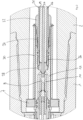
- Fig.1 shows a sectional view of a connection area of two rod sections 1, 2 for drilling a hole in the ground.
- the rod sections 1, 2 are screwed together by means of a screw connection 3.
- Each rod section 1, 2 has a two-wire system 4, 5, which is arranged essentially centered in the cavity of the respective rod section 1, 2.
- the two-wire system 4, 5 of a rod section 1, 2 is connected by means of centering stars 6, 7, which are each inserted at one of the ends of the rod sections 1, 2.
- the two-conductor system 4, 5 has a connection with two conductors 15, 17 and 14, 16, respectively, with insulation 18 and 19 being present between the conductors 15, 17 and 14, 16, respectively.
- the conductor 17 and 16 surrounds the conductor 15 and 14, respectively, and there is further insulation 20 and 21 around the conductor 17 and 16, respectively.
- the two-conductor systems 4, 5 each have a coaxial cable 12, 13.
- the two-wire system 5 of the Fig.1 right rod section 2 has a socket 8 at the end, by means of which the inner conductor 14 of the coaxial cable 13 can be connected to the inner conductor 15 of the coaxial cable 12.
- the inner conductor 15 of the coaxial cable 12 has a plug 9 at the end, which is inserted into the socket 8 of the Fig.1 right rod section 1 is positively inserted when screwing the rod sections 1, 2 together.
- Two insulation sleeves 10, 11 of the two-wire system 5 are arranged around the socket 8, of which the insulation sleeve 10 is located inside the outer insulation sleeve 11.
- the insulation sleeve 10 forms an inner insulation sleeve, while the insulation sleeve 11 forms an outer insulation sleeve.
- the insulation sleeve 10 protrudes from the socket 8 and the insulation sleeve 11 overlaps the insulation sleeve 10.
- the conductor 16 and the conductor 14 of the two-conductor system 5 as well as the conductor 15 and the conductor 17 are stripped in the area of the end of the two-conductor system 5 or 4 and are exposed without insulation 19, 21 and 18, 20.
- a counterpart 22, 23 is pushed onto the insulation 21, 20.
- an insulating sealing piece 24, 25 is pushed onto it.
- a ring 26, 27 that interacts with the counterpart 22, 23 is screwed to the counterpart 22, 23, with the insulating sealing piece 24, 25 pressing over a cone between the counterpart 22, 23 and the insulation 21, 20 and sealing it.
- the ring 26, 27 and the counterpart 22, 23 are designed to be electrically conductive.
- the inner conductors 14 and 15 are surrounded by an insulation 28, 29 in the front area.
- the conductor 14 is pressed onto the socket 8 at the end, while the conductor 15 is pressed onto the plug 9.
- an electrical conduction path is formed which is directed against the connection direction, which is directed "backwards” and is guided over the insulation 21 over the conductor 14.
- the electrical conduction path is connected again by the counterpart 22 by means of an electrically conductive connecting sleeve 30. in the connection direction.
- a wave spring 31 and a locking ring 32 are provided to hold the electrically conductive connection sleeve 30 in position.
- the centering star 7 is in electrically conductive contact with the electrically conductive connecting sleeve 30. In the embodiment shown, the centering star 7 is in electrical contact with the rod section 2, which is in electrically conductive contact with the rod section 1. An electrical connection to the conductor 17 is made via the centering star 6. The further electrical conduction path leads via the counterpart 23 with the ring 27, 33.
- An inner insulation sleeve 35 and an outer insulation sleeve 34 are arranged over the conductor 15 and are located in the front area.
- the inner insulation sleeve 35 engages in a projection of the inner insulation sleeve 10 to form a seal.
- the outer insulation sleeve 34 engages in a projection of the outer insulation sleeve 11 to form a seal with seals 36, 37.
- a tightness of 150 bar can be achieved.
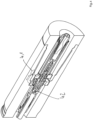
- Fig.4 shows without reference symbols electrical conduction paths with dashed lines 41, 42.
Landscapes
- Engineering & Computer Science (AREA)
- Life Sciences & Earth Sciences (AREA)
- Mining & Mineral Resources (AREA)
- Geology (AREA)
- Physics & Mathematics (AREA)
- Environmental & Geological Engineering (AREA)
- Fluid Mechanics (AREA)
- General Life Sciences & Earth Sciences (AREA)
- Geochemistry & Mineralogy (AREA)
- Remote Sensing (AREA)
- Mechanical Engineering (AREA)
- Geophysics (AREA)
- Electromagnetism (AREA)
- Earth Drilling (AREA)
- Cable Accessories (AREA)
Abstract
Description
- Die Erfindung betrifft ein Zwei-Leiter-System für Erdbohrgestängeschüsse zum Ausbilden eines Bohrstrangs für eine Erdbohrvorrichtung, einen Erdbohrgestängeschuss mit einem Zwei-Leiter-System, ein Erdbohrgestängeschuss-System sowie eine Verwendung beim Übertragen von elektrischen Signalen und/oder elektrischem Strom mit einem Zwei-Leiter-System für Erdbohrgestängeschüsse zum Ausbilden eines Bohrstrangs für eine Erdbohrvorrichtung.
- Bei einem Gestänge basierten Bohren im Erdreich mittels einer Erdbohrvorrichtung, insbesondere zur Herstellung von sogenannten Horizontalbohrungen, wird üblicherweise ein Bohrkopf mittels eines Bohrstrangs von einer an der Erdoberfläche oder in einer Baugrube angeordneten Antriebsvorrichtung angetrieben. Die dabei eingesetzten Bohrstränge können einzelne, miteinander verbundene Erdbohrgestängeschüsse aufweisen, die - dem Bohrverlauf entsprechend - nach und nach an das hintere Ende des bereits verbohrten Bohrstrangs angesetzt und mit diesem verbunden werden.
- Zur Versorgung von elektrischen Verbrauchern und/oder zur Übertragung von Signalen im Bohrstrang kann die Notwendigkeit bestehen, elektrische Verbindungen zwischen den einzelnen Erdbohrgestängeschüssen bereitzustellen. Hierzu ist es bekannt, einen Leiter bzw. ein Kabel zu verwenden, das im Inneren des Erdbohrgestängeschusses geführt werden kann.
- Ein Nachteil bei den sonst bisher gut funktionierenden Leitern in den Erdbohrgestängeschüssen kann sich durch einen möglichen Kurzschluss, insbesondere wenn beim Bohren bzw. Erstellen der Erdbohrung ein Bohrfluid verwendet wird und mehr als ein Leiter im Erdbohrgestängeschuss vorgesehen ist, ergeben.
- Ausgehend von diesem Stand der Technik lag der Erfindung die Aufgabe zugrunde, ein Zwei-Leiter-System für Erdbohrgestängeschüsse zum Ausbilden eines Bohrstrangs für eine Erdbohrvorrichtung, einen Erdbohrgestängeschuss mit einem Zwei-Leiter-System, ein Erdbohrgestängeschuss-System sowie eine Verwendung beim Übertragen von elektrischen Signalen und/oder elektrischem Strom mit einem Zwei-Leiter-System für Erdbohrgestängeschüsse zum Ausbilden eines Bohrstrangs für eine Erdbohrvorrichtung zu schaffen, mit dem bzw. der ein möglichst problemloses, insbesondere ohne Auftreten eines Kurzschlusses, Ausbilden und Lösen der Verbindung der Erdbohrgestängeschüsse möglich ist.
- Die Aufgabe wird durch die Gegenstände der nebengeordneten Patentansprüche gelöst. Vorteilhafte Weiterbildungen der Gegenstände der nebengeordneten Patentansprüche sind Gegenstand der jeweiligen abhängigen Patentansprüche und ergeben sich aus der nachfolgenden Beschreibung.
- Ein erster Kerngedanke der Erfindung ist es, eine Isolierung für ein Zwei-Leiter-System zu schaffen, mit dem eine bessere Isolationswirkung der mehreren Leiter untereinander bzw. zueinander gegeben ist, wobei zudem aber die Handhabung der Erdbohrgestängeschüsse, insbesondere beim Ausbilden und auch beim Trennen der Verbindung der Erdbohrgestängeschüsse miteinander erhalten bleibt. Die Erfindung verfolgt dabei den zunächst widersinnigen Ansatz, nicht nur eine Isolationshülse um einen der Leiter vorzusehen, sondern zwei Isolationshülsen um denselben Leiter vorzusehen, die insbesondere eine unterschiedliche Längserstreckung längs des einen oder der zwei Leiter haben. Der erste Kerngedanke der Erfindung kann die Patentfähigkeit alleine tragen.
- Gemäß dem ersten Aspekt schafft die Erfindung ein Zwei-Leiter-System für Erdbohrgestängeschüsse zum Ausbilden eines Bohrstrangs für eine Erdbohrvorrichtung, wobei das Zwei-Leiter-System einen isolierten Verbund aus einem ersten Leiter und einem zweiten Leiter aufweist, und der erste und der zweite Leiter jeweils an einem Ende aus dem Verbund in einer Verbindungsrichtung exponiert sind. Mindestens ein Abschnitt eines exponierten Endes eines der Leiter ist von einer inneren und einer äußeren Isolationshülse umfangsseitig umgeben. Hierdurch kann eine effektive Isolierung des einen Leiters geschaffen werden.
- Der Begriff "Zwei-Leiter-System" im Sinne der Erfindung beschreibt ein System, welches in einem Erdbohrgestängeschuss, der seinerseits zum Ausbilden eines Bohrstrangs für eine Erdbohrvorrichtung ausgestaltet ist, angeordnet werden kann. Das Zwei-Leiter-System kann eine an den Erdbohrgestängeschuss, in dem es angeordnet werden soll, angepasste Länge aufweisen. Endseitig kann jeweils das Zwei-Leiter-System in dem Erdbohrgestängeschuss fixiert werden. Eine Fixierung des Zwei-Leiter-Systems im Erdbohrgestängeschuss kann im Wesentlichen mittig im Erdbohrgestängeschuss erfolgen.
- Die Fixierung im endseitigen Bereich des Zwei-Leiter-Systems im Erdbohrgestängeschuss kann bevorzugt über Zentriersterne erfolgen.
- Ein hier beschriebenes Zwei-Leiter-System kann verwendet werden, um einen schon bestehenden Erdbohrgestängeschuss "aufzuwerten", sodass im Erdbohrgestängeschuss ein System in Form des Zwei-Leiter-Systems angeordnet werden kann, mittels dessen mehrere, d.h. hier mindestens zwei, Leiter für die Übertragung von Strom und/oder Signalen über zumindest einen Teilabschnitt des Bohrstrangs verwendet werden kann. Dem Anwender einer Gestänge basierten Erdbohrvorrichtung kann mittels des Zwei-Leiter-Systems ein Mehrwert geboten werden, dass bspw. Einheiten im Bereich des Bohrkopfs des Bohrstrangs mit Strom und/oder Signalen versorgt werden können. Insbesondere die Zurverfügungstellung von mehr als einem Leiter bietet dem Anwender einen nicht zu unterschätzenden Mehrwert, da die beiden Leiter unabhängig voneinander genutzt und hinsichtlich ihrer Verwendung auch für zukünftige Aufgaben und/oder am Bohrkopf angeordnete Einheiten nicht beschränkt sind.
- Der Begriff "Leiter" im Sinne der Beschreibung umfasst einen elektrisch leitfähigen Leiter. Der Begriff "Zwei-Leiter" umfasst im Sinne der Beschreibung ein System, bei dem mindestens zwei Leiter vorhanden sind. Es kann auch vorgesehen sein, dass genau zwei Leiter in dem Zwei-Leiter-System vorhanden sind.
- Der Begriff "Erdbohrgestängeschuss" im Sinne der Beschreibung umfasst einzelne, insbesondere starre, miteinander mittelbar oder unmittelbar verbindbare Gestängeschüsse, die zum Ausbilden eines Bohrgestänges oder eines Bohrstrangs in längsaxialer Richtung miteinander verbunden werden können. Die Gestängeschüsse können zur Verbindung miteinander unter mechanischer Zwischenschaltung eines Zwischenelements oder ohne Zwischenschaltung eines Zwischenelements zusammengesteckt oder zusammengeschraubt werden. Mischformen aus Zusammenstecken und Zusammenschrauben der Erdbohrgestängeschüsse sind möglich. Die Verbindung der Erdbohrgestängeschüsse kann insbesondere jeweils mittels eines Zusammenschraubens oder Zusammensteckens eines Endes eines Erdbohrgestängeschusses mit einem anderen Ende eines anderen Erdbohrgestängeschusses erfolgen.
- Der Begriff "Bohrstrang" im Sinne der Beschreibung umfasst mehrere miteinander verbundene Erdbohrgestängeschüsse. Der Bohrstrang kann sich in längsaxialer Richtung entlang der Längsachse der Erdbohrgestängeschüsse in einer Bohrstrangachse, die mit den Längsachsen der Erdbohrgestängeschüsse im Wesentlichen kongruent ist bzw. koinzidiert, erstrecken. Der Bohrstrang kann an einem, insbesondere vorderseitigen, Ende einen Bohrkopf und gegebenenfalls eine vorhandene Bohrkopfspitze, die als Bohrwerkzeug (beispielsweise als Aufweitkopf) ausgestaltet sein kann oder einen dem Bohrkopf benachbarten Bereich, der insbesondere die gleiche Ausrichtung wie der Bohrkopf aufweisen kann, aufweisen. Der Bohrstrang kann im Bereich des Bohrkopfes oder einem dem Bohrkopf benachbarten Bereich einen Sensorabschnitt bzw. ein Sensorgehäuse aufweisen, in dem ein oder mehrere Sensoren angeordnet sein können.
- Der Begriff "Erdbohrvorrichtung" umfasst im Sinne der Beschreibung eine (und damit jede) Vorrichtung, welche insbesondere einen Erdbohrgestängeschüsse aufweisenden Bohrstrang in einem bestehenden oder zu erstellenden Kanal im Erdreich bewegen kann, um eine Bohrung, insbesondere eine Horizontalbohrung (HD), zu erstellen oder aufzuweiten oder Rohrleitungen oder andere lange Körper in das Erdreich einzuziehen. Bei der Erdbohrvorrichtung kann es sich insbesondere um eine HD-Vorrichtung handeln. Eine Erdbohrvorrichtung kann eine einen Bohrstrang antreibende Vorrichtung sein, die insbesondere Erdreich verdrängend arbeiten kann. Der Bohrstrang kann translatorisch und/oder rotatorisch in längsaxialer Richtung des Bohrstrangs in das Erdreich eingebracht werden. Der Bohrstrang kann mittels der Erdbohrvorrichtung durch eine Zug- oder Druckbeaufschlagung im Erdreich bewegt werden.
- Der Begriff "Erdreich" im Sinne der Beschreibung umfasst jedwede Art von Material, insbesondere Erde, Sand, Fels, Gestein und/oder Stein, in welchem bestehende oder zu erstellende, vorzugsweise zumindest abschnittsweise horizontale, Kanäle bzw. Bohrungen eingebracht werden können. Eine unterirdische Anordnung des Erdreichs ist bevorzugt, aber nicht zwingend notwendig.
- Im Sinne der Beschreibung umfasst der Begriff "isolierter Verbund" einen ersten Leiter und einen zweiten Leiter, die gemeinsam gehandhabt werden können. Der erste Leiter und der zweite Leiter können zusammen als ein Element bzw. einstückig gehandhabt werden. Dabei drückt der Begriff "isoliert" aus, dass die beiden Leiter in einem Verbund derart vorliegen, dass eine Isolierung nach außen vorhanden ist. Erster und zweiter Leiter sind von einer Isolierung umgeben, die umfangsseitig um den ersten und/oder den zweiten Leiter angeordnet ist.
- Der Begriff "Verbindungsrichtung" umfasst im Sinne der Beschreibung eine Richtung, die ausdrückt, dass eine Verbindung in längsaxialer Richtung des Zwei-Leiter-Systems vorliegt, die von dem Zwei-Leiter-System bzw. dem ersten und/oder zweiten Leiter, in längsaxialer Richtung des Zwei-Leiter-Systems wegführt.
- Sofern das Zwei-Leiter-System in dem Erdbohrgestängeschuss angeordnet ist, so weist die Verbindungsrichtung aus dem bzw. den Enden des Erdbohrgestängeschusses heraus.
- Einer der Leiter kann sowohl von der inneren als auch der äußeren Isolationshülse umfangsseitig zumindest abschnittsweise umgeben sein. In einem Abschnitt kann sowohl die innere als auch die äußere Isolationshülse den einen Leiter umgeben. Es kann vorgesehen sein, dass eine der Isolationshülsen, insbesondere die äußere Isolationshülse über der anderen Isolationshülse, insbesondere der inneren Isolationshülse, übersteht. Ein Überstand in längsaxialer Richtung kann in einer Richtung vom Zwei-Leiter-System weg und/oder in Richtung des Zwei-Leiter-Systems vorliegen. Es kann vorgesehen sein, dass eine der beiden Isolationshülsen, insbesondere die äußere Isolationshülse, die andere Isolationshülse, insbesondere die innere Isolationshülse, insbesondere klammerartig, bezogen auf die Längsachse der Isolationshülse(n) bzw. des Zwei-Leiter-Systems umgreift. Die eine der Isolationshülsen, insbesondere die äußere Isolationshülse, kann eine Länge aufweisen, die mindestens um das 1,5-fache, insbesondere mindestens um das 2-fache, länger ist als die andere Isolationshülse.
- In einem weiteren, zweiten Aspekt folgt die Erfindung dem Kerngedanken, der für sich selbst schon alleine patentbegründend ist, eine Ausgestaltung vorzusehen, dass zumindest ein Abschnitt eines elektrischen Leitungspfads anders als im Stand der Technik ausgebildet ist. Es ist ein in Richtung des Zwei-Leiter-Systems ausgebildeter Abschnitt, der sich an das exponierte Ende eines der Leiter anschließt, vorhanden. Es wurde mit der bisherigen Überlegung gebrochen, dass der Leitungspfad ausgehend vom exponierten Ende des einen Leiters in im Wesentlichen gerader, nach vorne gerichteter Weise ausgebildet sein muss, der im Wesentlichen vom Leiter weg gerichtet ist. Es wurde erkannt, dass zum Reduzieren von Kurzschlüssen der Leiter untereinander, ein elektrischer Leitungspfad vorgesehen sein kann, der zumindest einen Abschnitt aufweist, der von einem exponierten Ende des einen Leiters des Zwei-Leiter-Systems in eine Richtung geführt wird, die vom benachbarten Ende des Zwei-Leiter-Systems weg in Richtung des Zwei-Leiter-Systems zurück gerichtet ist. Der elektrische Leitungspfad, mittels dem mittelbar oder unmittelbar das exponierte Ende des einen Leiters mit einem Leiter eines anderen Zwei-Leiter-Systems verbunden werden kann, weist einen Abschnitt auf, der zwischen dem exponierten Ende des einen Leiters und einem Leiter eines weiteren Zwei-Leiter-Systems liegt. Der Abschnitt führt vom exponierten Ende und dem zum exponierten Ende benachbarten Ende des Zwei-Leiter-Systems weg und zwar in längsaxialer Richtung betrachtet in die entgegengesetzte Richtung. Der elektrische Leitungspfad kann einen nach "rückwärts" gerichteten Anteil haben, der einen Abschnitt aufweist, der über einen Abschnitt des Leiters, dessen exponiertes Ende mit dem elektrischen Leitungspfad in elektrischem Kontakt steht, rückgeführt wird. Durch die Ausgestaltung des elektrischen Leitungspfades, der von dem exponierten Ende (und dem zum exponierten Ende benachbarten Ende des Zwei-Leiter-Systems) weg in Richtung eines mittigen Bereichs hinsichtlich der Längserstreckung des Zwei-Leiter-Systems geführt ist, können Abschnitte des Leitungspfads des einen Leiters in radialer Richtung "übereinander" angeordnet sein. Zwei der "übereinander" bzw. im Wesentlichen parallel angeordneten Abschnitte des einen Leiters bzw. dessen elektrischen Leitungspfads können mittels einer Isolierung (die auch die Isolierung des Verbunds sein kann) beabstandet zueinander angeordnet sein. Es kann die Möglichkeit geschaffen werden, die beiden Leiter im Erdbohrgestängeschuss derart voneinander zu trennen, dass insbesondere ein Kurzschluss weitestgehend unterbunden ist. Eine Verhinderung von Kurzschlüssen der beiden Leiter kann effektiv weitestgehend unterbunden werden.
- Gemäß dem zweiten Aspekt schafft die Erfindung ein Zwei-Leiter-System für Erdbohrgestängeschüsse zum Ausbilden eines Bohrstrangs für eine Erdbohrvorrichtung, bei dem das Zwei-Leiter-System einen isolierten Verbund aus einem ersten Leiter und einem zweiten Leiter aufweist. Der erste und der zweite Leiter sind jeweils an einem Ende aus dem Verbund in einer Verbindungsrichtung exponiert. Ein elektrischer Leitungspfad ist für mindestens einen der Leiter ausgebildet, der sich von dem exponierten Ende des einen Leiters weg über die Isolierung des einen Leiters und/oder des Verbundes entgegen der Verbindungrichtung erstreckt und von dort in Verbindungrichtung isoliert am Ende des einen Leiters vorbeiführt. Hierdurch kann dem zweiten Aspekt der Erfindung Rechnung getragen werden, Kurzschlüsse effektiv zu verhindern.
- Die beiden Aspekte hinsichtlich des Zwei-Leiter-Systems können zwanglos miteinander kombiniert werden. Es ist keine Schwierigkeit vorhanden, eine innere und eine äußere Isolationshülse zusammen mit dem beschriebenen elektrischen Leitungspfad vorzusehen. Die beiden Aspekte können einander ergänzen.
- Der Begriff "exponiert" umfasst im Sinne der Beschreibung die Ausgestaltung, dass ein Zugriff auf den Leiter insbesondere in radialer Richtung bzw. an seinem Umfang möglich ist. Der Begriff "exponiert" umfasst damit die Ausgestaltung, dass keine Isolierung umfangsseitig in dem exponierten Bereich bzw. Ende am Leiter vorhanden ist.
- Der Begriff "elektrischer Leitungspfad" umfasst im Sinne der Beschreibung eine Ausbildung eines elektrisch leitenden Abschnitts bzw. Pfades, entlang dem ein Strom bzw. ein Signal geführt werden kann. Der elektrische Leitungspfad des mindestens einen Leiters bzw. der elektrische Leitungspfad ausgehend für den mindestens einen Leiter von seinem exponierten Ende kann dabei derart gewählt sein, dass ein Abschnitt des Leitungspfads mittels einer Isolierung des einen Leiters und/oder des Verbundes beabstandet zum einen Leiter gebildet ist, der bezogen auf eine radiale Richtung des Leiters "neben", "über" bzw. "unter" dem Leiter gebildet ist. Bezogen auf die Verbindungsrichtung wird ein Abschnitt des elektrischen Leitungspfades gebildet werden, der entgegen der Verbindungsrichtung gerichtet ist.
- Durch die Ausgestaltung des beschriebenen "elektrischen Leitungspfads" wird der Ansatz verfolgt, einen "verlängerten" Leitungspfad auszubilden, als es bisher im Stand der Technik der Fall war. Die "Verlängerung" des elektrischen Leitungspfads des einen Leiters kann aber zu einer Verbesserung des Kurzschlussverhaltens, insbesondere bei der Verwendung einer Bohrflüssigkeit bzw. eines Bohrfluids, welches durch die Erdbohrgestängeschüsse geführt wird, führen.
- In einer bevorzugten Ausführungsform umfasst der Verbund ein Koaxialkabel und die zwei Leiter sind der Innen- und der Außenleiter des Koaxialkabels. Hierdurch kann eine besonders einfache Ausgestaltung einer Komponente des Zwei-Leiter-Systems erreicht werden. Koaxialkabel sind gut handhabbar und verwendbar.
- In einer bevorzugten Ausführungsform wird das exponierte Ende des einen Leiters mittels eines am exponierten Ende anliegenden elektrisch leitenden Rings kontaktiert, mittels dem die Isolierung des einen Leiters und/oder des Verbunds durch Anpressen eines isolierenden Dichtungsstücks auf die Isolierung des einen Leiters und/oder des Verbunds abgedichtet ist. Durch die vorgenannte Ausgestaltung kann erreicht werden, dass zum einen eine einfache Art der Kontaktierung möglich ist, aber auch zum anderen eine Integrität des Verbundes und/oder der Isolierung des Leiters weitestgehend sichergestellt werden kann. Der Ring kann nicht nur für die Bereitstellung eines Teils des elektrischen Leitungspfads verwendet werden, sondern auch dazu, die Integrität des isolierten Verbundes auch bei Anwesenheit von mit Druck beaufschlagtem Bohrfluid aufrechtzuerhalten. Bei dem mit Druck beaufschlagten Bohrfluid könnte ohne eine Abdichtung der Fall eintreten, dass das Bohrfluid im Bereich des exponierten Endes des Leiters "unter" die Isolierung des einen Leiters bzw. des Verbundes gelangen könnte und die Isolierung könnte sich auf Dauer ablösen. Es kann ein synergistischer Effekt erzielt werden, indem der elektrisch leitende Ring sowohl die elektrische Ausbildung des elektrischen Leitungspfads als auch eine Integrität der Isolierung des einen Leiters bzw. des Verbundes bewirken kann.
- In einer bevorzugten Ausführungsform ist der Ring über oder in ein Gegenstück schraubbar, welches die Isolierung des einen Leiters und/oder des Verbunds anliegend an der äußeren Oberfläche des Verbunds umgibt. Das isolierende Dichtungsstück kann zusammen mit dem Ring mit einer axialen Richtungskomponente auf die Isolierung des einen Leiters und/oder des Verbunds beim Verschrauben gepresst werden. Hierdurch kann eine einfach ausgestaltete, einfach konstruierbare und planbare Verbindung geschaffen werden, die lediglich ein Verschrauben des Rings und des Gegenstücks erforderlich machen kann.
- In einer bevorzugten Ausführungsform ist ein vorderer Abschnitt des Rings von einer Isolierungshülse, insbesondere der äußeren Isolierungshülse, in Verbindungsrichtung umgeben. Es kann erreicht werden, dass eine Isolierungshülse, insbesondere die äußere Isolierungshülse, den Ring in einer Richtung, die der Verbindungrichtung entspricht, und gemeinhin als "nach vorne" bezeichnet wird (von dem Zwei-Leiter-System weg), abschirmt, um eine "Distanz" zwischen den Leitern bzw. dem ausgebildeten elektrischen Leitungspfad des einen Leiters zum anderen Leiter bzw. dessen exponierten Ende zu schaffen. Die Isolierungshülse kann als eines von gegebenenfalls mehreren Elementen den Effekt bzw. das Ausbilden des "rückwärts gerichteten" elektrischen Leitungspfads unterstützen.
- In einer bevorzugten Ausführungsform umgibt eine elektrisch leitende Verbindungshülse eine Isolierungshülse, insbesondere zumindest abschnittsweise die äußere Isolierungshülse, und erstreckt sich über den Ring und/oder das Gegenstück zumindest teilweise. Es kann ein in Verbindungsrichtung vorgesehener Abschnitt des elektrischen Leitungspfads mittels der elektrisch leitenden Verbindunghülse geschaffen werden, die in den hinteren/rückwärtigen Bereich (in den mittigen Bereich des Zwei-Leiter-Systems), in den der elektrische Leitungspfad zunächst von dem exponierten Ende des einen Leiters ausgebildet ist, führt. Der elektrische Leitungspfad der zunächst von dem exponierten Ende rückwärtig, d.h. entgegen der Verbindungsrichtung, geführt wurde, kann mittels der Verbindungshülse wieder nach vorne, d.h. in Verbindungrichtung, geführt werden. Mittels der elektrisch leitenden Verbindungshülse liegt ein einfach handhabbares, konstruierbares und einsetzbares Element vor. Zudem kann eine einfache Steckverbindung verwendet werden. Die Verbindungshülse kann über den Ring und/oder das Gegenstück des Rings geschoben werden.
- In einer bevorzugten Ausführungsform umfasst das Zwei-Leiter-System für Erdbohrgestängeschüsse zum Ausbilden eines Bohrstrangs für eine Erdbohrvorrichtung ein Überdruckventil zum Ableiten eines Überdrucks aus dem Bereich des Zwei-Leiter-Systems. Hierdurch kann die Möglichkeit geschaffen werden, einen Druck im Bereich des Zwei-Leiter-Systems unter bzw. im Wesentlichen gleich oder geringfügig höher als ein Druckniveau außerhalb des Zwei-Leiter-Systems zu halten. Vorteilhaft kann damit ein zu hoher Überdruck im Bereich des Zwei-Leiter-Systems weitestgehend verhindert werden. Ein zu hoher Überdruck könnte beispielsweise dazu führen, dass Flüssigkeit von dem Bereich des Zwei-Leiter-Systems an den bzw. die elektrischen ersten bzw. zweiten Leiter gelangen kann, was zu einem Kurzschluss führen könnte.
- Ein Vorsehen eines Überdruckventils scheint zunächst ohne den Erkenntnisgewinn der Erfindung widersinnig, da mit dem Überdruckventil grundsätzlich eine Öffnung vorgesehen sein muss, über die der Überdruck abgebaut werden kann. Eine derartige Öffnung gilt es für den Fachmann allerdings in der Regel zu vermeiden, da die Öffnung an sich eine Gefahrenquelle für einen Flüssigkeits- oder einen Schmutzeintrag in den Bereich des Zwei-Leiter-Systems liefern kann. Es ist das Verdienst der Erfindung, erkannt zu haben, dass durch eine gerichtete Öffnung überhaupt ein Vorteil erreicht werden kann.
- Unter dem Begriff "Überdruckventil zum Ableiten eines Überdrucks" wird jedwedes Ventil verstanden, welches ansprechen bzw. öffnen kann, wenn der Druck im Bereich des Zwei-Leiter-Systems über einen Ansprechdruck ansteigt. Als Ansprechdruck kann im Wesentlichen der Druck verstanden werden, der oberhalb des Drucks der Umgebung des Bohrstrangs außen entspricht. Es versteht sich, dass durch die sicherzustellende dichtende Wirkung im Überdruckventil, die eine rückstellende bzw. vorgespannte Wirkung zwischen Verschluss bzw. Absperrkörper und Dichtfläche bzw. Ventilsitz bedingt, der Überdruck, bei dem das Überdruckventil anspricht, geringfügig höher sein kann als der Umgebungsdruck.
- Unter dem Begriff "Bereich des Zwei-Leiter-Systems" ist ein Bereich zu verstehen, der für die Verbindung eines ersten und/oder eines zweiten elektrischen Leiters des Zwei-Leiter-Systems mit einem entsprechenden ersten und/oder zweiten elektrischen Leiter des Zwei-Leiter-Systems vorgesehen ist.
- Die Erfindung schafft auch einen Erdbohrgestängeschuss mit einem Zwei-Leiter-System. Das Zwei-Leiter-System ist, insbesondere mittels mindestens einem Zentrierstern, im Erdbohrgestängeschuss im Wesentlichen mittig in einem sich längs der Längsachse des Erdbohrgestängeschusses erstreckenden Hohlraum angeordnet. Die Erdbohrgestängeschüsse können mit dem beschriebenen Zwei-Leiter-System vorkonfektioniert werden. Die Anordnung mittels mindestens eines Zentriersterns, wobei an jedem Ende des Erdbohrgestängeschusses ein Zentrierstern vorgesehen sein kann, erlaubt auch eine einfache Wartung und/oder einen einfachen Ersatz bei einem Verschleiß.
- Die Erfindung schafft auch ein Erdbohrgestängeschuss-System mit mehreren Erdbohrgestängeschüssen, die ein Zwei-Leiter-System aufweisen, wobei die Erdbohrgestängeschüsse miteinander unter Ausbildung eines Abschnitts eines Bohrstrangs miteinander verbindbar sind.
- An mindestens einem Erdbohrgestängeschuss oder vorzugsweise an allen Erdbohrgestängeschüssen des Erdbohrgestänge-Systems kann an mindestens einem Ende, bevorzugt an genau einem Ende, mindestens ein oder mehrere Überdruckventil(e) ausgestaltet sein. Das oder die Überdruckventile kann bzw. können derart ausgestaltet und angeordnet sein, einen Überdruck gegenüber dem Umgebungsdruck des Bohrstrangs im Hohlraum des Erdbohrgestängeschusses bzw. im Bereich des Zwei-Leiter-Systems zu verhindern. Mindestens ein Überdruckventil an einem Ende des Erdbohrgestängeschusses kann ausreichend sein, bei einer Verbindung zweier Erdbohrgestängeschüsse einen Überdruck abzuleiten. Insbesondere kann der Überdruck abgeleitet werden, der sich ergeben kann, wenn zwei Erdbohrgestängeschüsse miteinander verbunden werden.
- Das Überdruckventil kann als eine oder mehrere verschließbare Öffnung(en) in einem Erdbohrgestängeschuss ausgestaltet sein, welche den Hohlraum, in dem das Zwei-Leiter-System angeordnet ist, mit der Umgebung des Bohrstrangs verbinden kann. Die Öffnungen können als verschließbare Durchgangsöffnungen von dem Bereich des für die Verbindung vorgesehenen Zwei-Leiter-Systems bzw. dem Hohlraum bis nach außen reichen.
- Ein Erdbohrgestängeschuss kann zur Ausbildung eines Überdruckventils mindestens einen Kanal in seiner Wand aufweisen, der jedwede Ausgestaltung hinsichtlich seiner Richtung und Querschnittsform aufweisen kann. Es können auch mehrere Kanäle zur Ausbildung eines Überdruckventils vorgesehen sein.
- Eine geradlinige Ausgestaltung eines Kanals kann für eine einfache Herstellung vorteilhaft sein. Eine geradlinige Ausgestaltung quer zur Längsachse des Erdbohrgestängeschusses kann bevorzugt sein, um eine möglichst kurze Ausgestaltung des Kanals zu ermöglichen und/oder die Herstellung zu vereinfachen und/oder eine möglichst geringe Schwächung der Integrität des Erdbohrgestängeschusses zu erreichen. Eine kurvige und oder geradlinige Ausgestaltung des Kanals unter einem beliebigen Winkel zur Längsachse des Erdbohrgestängeschusses ist nicht ausgeschlossen.
- Eine runde, insbesondere kreisförmige, Querschnittsform des Kanals kann die Herstellung vereinfachen, da der Kanal beispielsweise als Bohrung erzeugt werden kann. Eine andere Ausgestaltung als eine runde Querschnittsform ist nicht ausgeschlossen, insbesondere eine zumindest abschnittsweise gerade Ausgestaltung der Querschnittsform ist möglich.
- Es kann vorgesehen sein, dass die Öffnung bzw. der Kanal einen in einer Richtung entgegen einen Überdruck im Hohlraum bzw. dem Bereich des Zwei-Leiter-Systems wirkenden (schließenden) Verschluss, der beispielsweise klappenförmig ausgestaltet sein kann, aufweist. Beispielsweise kann die Öffnung bzw. der Kanal eine elastische oder bewegliche klappenförmige Ausgestaltung eines Verschlusses aufweisen, der an der Öffnung bzw. der Kanalwand zumindest teilweise anliegen und gegen die Öffnung bzw. die Kanalwand vorgespannt sein kann. Erhöht sich der Druck im Hohlraum bzw. im Bereich des Zwei-Leiter-Systems, kann sich der Verschluss von der Öffnung bzw. der Kanalwand abheben und nach einer Druckverminderung wieder in die am der Öffnung bzw. der Kanalwand anliegende Stellung zurückkehren.
- Es kann vorgesehen sein, dass die eine oder mehrere verschließbare(n) Öffnung(en) bzw. der eine Kanal oder die mehreren Kanäle in eine Nut am Erdbohrgestängeschuss münden, wobei zum Verschließen der Öffnung(en) bzw. des Kanal bzw. der Kanäle ein O-Ring in der Nut angeordnet sein kann. Es kann auch vorgesehen sein, dass die Öffnungen bzw. Kanäle in unterschiedliche Nuten münden, die jeweils einen O-Ring aufweisen können. Eine Nut mit einem O-Ring kann die Herstellung und Planung vereinfachen. Bei Auftreten eines Überdrucks kann sich der O-Ring zum Abbau des Überdrucks kurzzeitig (minimal) anheben und nach erfolgter Druckverminderung wieder in der Nut auf der Öffnung aufliegend die Öffnung verschließen.
- Alternativ oder zusätzlich kann ein Überdruckventil dadurch ausgestaltet sein, dass ein oder mehrere Nutringe vorgesehen sind, der bzw. die einen Erdbohrgestängeschuss umfangsseitig umgeben und mit einem weiteren (mit dem einen Erdbohrgestängeschuss verbundenen) Erdbohrgestängeschuss abdichtet bzw. abdichten. Derartige Nutringe sind auf dem Gebiet der Hydraulikzylinder bekannt und ermöglichen einen Druckabbau in eine Richtung, wohingegen in der anderen Richtung eine Abdichtung gegeben ist. Werden die Erdbohrgestängeschüsse verbunden, so kann ein sich dadurch ergebender Druckaufbau abgebaut werden. Wirkt ein erhöhter Druck von außen auf die Verbindungsstelle mit dem oder den Nutring(en) so dichtet der bzw. die Nutring(e) ab.
- Es kann eine einfache Verbindung einer endseitigen Verbindung der Erdbohrgestängeschüsse vorgesehen sein, die als Steck- und/oder Schraubverbindung ausgestaltet sein kann. Die Enden der Erdbohrgestängeschüsse und die darin angeordneten Enden des Zwei-Leiter-Systems können derart ausgerichtet sein, dass es zu einer zwangsgeführten Verbindung der Enden des Zwei-Leiter-Systems bei einer Verbindung der Enden zweier Erdbohrgestängeschüsse kommt. Beispielsweise können die Erdbohrgestängeschüsse miteinander verschraubt werden, und beim Verschraubungsvorgang können die beiden Enden des Zwei-Leiter-Systems in einen Steckkontakt miteinander gebracht werden.
- Das Zwei-Leiter-System ist, insbesondere mittels mindestens einem Zentrierstern, im Erdbohrgestängeschuss im Wesentlichen mittig in einem sich längs der Längsachse des Erdbohrgestängeschusses erstreckenden Hohlraum angeordnet. Die Erdbohrgestängeschüsse können mit dem beschriebenen Zwei-Leiter-System vorkonfektioniert werden. Die Anordnung mittels mindestens eines Zentriersterns, wobei bevorzugt an jedem Ende des Erdbohrgestängeschusses ein Zentrierstern vorgesehen sein kann, erlaubt auch eine einfache Wartung und/oder einen einfachen Ersatz bei einem Verschleiß.
- In einer besonders bevorzugten Ausführungsform kann ein elektrischer Leitungspfad bzw. ein Abschnitt desselben, insbesondere bezogen auf den elektrischen Leitungspfad, der für einen der Leiter der in der Beschreibung beschrieben ist und einen "rückwärtig geführten bzw. gerichteten" Abschnitt aufweist, über die Verbindung der beiden Erdbohrgestängeschüsse untereinander ausgebildet sein. Es kann somit ein Abschnitt eines elektrisches Leitungspfads über die Verbindung der Erdbohrgestängeschüsse untereinander vorliegen. Da das Außengehäuse des Erdbohrgestängeschusses ein elektrisch leitendes Material aufweist, kann sich eine derartige Ausbildung anbieten, da diese keine weiteren Elemente, die vorgesehen werden müssen, benötigt.
- Ein Abschnitt eines elektrischen Leitungspfads für mindestens einen der Leiter kann zu einem ein elektrisch leitendes Material aufweisenden Zentrierstern führen, der in elektrisch leitendem Kontakt mit dem Gehäuse des Erdbohrgestängeschusses steht. Ein Abschnitt des elektrischen Leitungspfads kann für mindestens einen der Leiter über die Verbindung der beiden Erdbohrgestängeschüsse geführt werden und von dem Zentrierstern des weiteren Erdbohrgestängeschusses wieder in den Leiter des isolierten Verbundes des weiteren Erdbohrgestängeschusses geführt werden.
- Es ist alternativ oder zusätzlich möglich, dass eine unmittelbare Verbindung der Zentriersterne untereinander hergestellt wird und auf eine Ausbildung eines Abschnitts des elektrischen Leitungspfads über das Gehäuse der Erdbohrgestängeschüsse verzichtet werden kann. Es kann ein Kontaktmechanismus vorgesehen sein, der bei Ausbildung einer Verbindung zwischen Erdbohrgestängeschüssen benachbarte endseitige Zentriersterne elektrisch miteinander verbindet. Beispielsweise kann ein sich in Längsrichtung des Erdbohrgestängeschusses erstreckendes elektrisch leitendes Element an einem der Zentriersterne vorgesehen sein, welches beim Ausbilden der Verbindung der beiden Erdbohrgestängeschüsse den anderen Zentrierstern, der ebenfalls elektrisch leitend ausgestaltet ist, kontaktiert.
- Gemäß dem ersten Aspekt der Erfindung schafft die Erfindung auch eine Verwendung beim Übertragen von elektrischen Signalen und/oder elektrischem Strom mit einem Zwei-Leiter-System für Erdbohrgestängeschüsse zum Ausbilden eines Bohrstrangs für eine Erdbohrvorrichtung. Das Zwei-Leiter-System weist einen isolierten Verbund aus einem ersten Leiter und einem zweiten Leiter auf. Der erste und der zweite Leiter sind jeweils an einem Ende aus dem Verbund in einer Verbindungsrichtung exponiert. Zum umfangsseitigen Isolieren mindestens eines Abschnitts eines exponierten Endes eines der Leiter wird eine innere und einer äußere Isolationshülse verwendet.
- Gemäß dem zweiten Aspekt der Erfindung schafft die Erfindung auch eine Verwendung zum Übertragen von elektrischen Signalen und/oder elektrischem Strom mit einem Zwei-Leiter-System für Erdbohrgestängeschüsse zum Ausbilden eines Bohrstrangs für eine Erdbohrvorrichtung, wobei das Zwei-Leiter-System einen isolierten Verbund aus einem ersten Leiter und einem zweiten Leiter aufweist. Der erste und der zweite Leiter sind jeweils an einem Ende aus dem Verbund in einer Verbindungsrichtung exponiert. Es wird ein elektrischer Leistungspfad für mindestens einen der Leiter verwendet, der sich von dem exponierten Ende des einen Leiters weg über die Isolierung des einen Leiters und/oder des Verbundes entgegen der Verbindungsrichtung erstreckt. Von dort wird der elektrische Leitungspfad in Verbindungsrichtung isoliert am Ende des einen Leiters vorbeigeführt.
- Die in der Beschreibung und den Ansprüchen verwendeten Ordnungszahlen stellen keine Bevorzugung, keine bestimmte Rangfolge und keine geordnete Reihe dar, sondern die Ordnungszahlen werden zur Identifikation bzw. Unterscheidung der mit den Ordnungszahlen versehenen Elemente verwendet.
- Sofern in der Beschreibung Ausführungen für das Zwei-Leiter-System und/oder für den Erdbohrgestängeschuss gemacht werden, so gelten die Ausführungen hinsichtlich der beiden Vorrichtungen, nämlich das Zwei-Leiter-System und den Erdbohrgestängeschuss sowie das Erdbohrgestänge-System auch als Offenbarung für die in der Beschreibung beschriebene Verwendung beim Übertragen von elektrischen Signalen und/oder elektrischem Strom. Sofern bei den Vorrichtungen auf vorrichtungsseitige Merkmale abgestellt wird, so wird hierunter auch eine Beschreibung verstanden, dass die vorrichtungsseitigen Merkmale beschreibende Verfahrensmerkmale, Verfahrensschritte bzw. Merkmale hinsichtlich einer Verwendung offenbart sind.
- Die vorstehenden Ausführungen stellen ebenso wie die nachfolgende Beschreibung beispielhafter Ausführungsformen keinen Verzicht auf bestimmte Ausführungsformen oder Merkmale dar.
- Die Erfindung wird nachfolgend anhand von einem in der Zeichnung dargestellten Ausführungsbeispiel näher erläutert.
- In den Zeichnungen zeigt:
- Fig. 1
- eine Schnittdarstellung eines Verbindungsbereichs zweier Gestängeschüsse eines Bohrstrangs, wobei in den beiden Gestängeschüssen jeweils ein Zwei-Leiter-System angeordnet ist;
- Fig. 2
- eine vergrößerte Darstellung der
Fig. 1 ; - Fig. 3
- eine vergrößerte Darstellung der
Fig. 1 ; und - Fig. 4
- elektrische Leitungspfad.
-
Fig. 1 zeigt in einer Schnittdarstellung einen Verbindungsbereich zweier Gestängeschüsse 1, 2 für ein Einbringen einer Bohrung in das Erdreich. Die Gestängeschüsse 1, 2 sind miteinander mittels einer Schraubverbindung 3 verschraubt. - Jeder Gestängeschuss 1, 2 weist ein Zwei-Leiter-System 4, 5 auf, welches im Wesentlichen zentriert im Hohlraum des jeweiligen Gestängeschusses 1, 2 angeordnet ist. Das Zwei-Leiter-System 4, 5 eines Gestängeschusses 1, 2 ist mittels Zentriersternen 6, 7, die jeweils endseitig an einem der Enden der Gestängeschüsse 1, 2 eingebracht sind, fixiert.
- Das Zwei-Leiter-System 4, 5 weist einen Verbund mit zwei Leitern 15, 17 bzw. 14, 16 auf, wobei zwischen den Leitern 15, 17 bzw. 14, 16 eine Isolierung 18 bzw. 19 vorhanden ist. Der Leiter 17 bzw. 16 umgibt den Leiter 15 bzw. 14 und um den Leiter 17 bzw. 16 ist eine weitere Isolierung 20 bzw. 21 vorhanden. Die Zwei-Leiter-Systeme 4, 5 weisen je ein Koaxialkabel 12, 13 auf.
- Das Zwei-Leiter-System 5 des in der
Fig. 1 rechten Gestängeschusses 2 weist endseitig eine Buchse 8 auf, mittels derer der innere Leiter 14 des Koaxialkabels 13 mit dem inneren Leiter 15 des Koaxialkabels 12 verbunden werden kann. Der innere Leiter 15 des Koaxialkabels 12 weist endseitig einen Stecker 9 auf, der in die Buchse 8 des in derFig. 1 rechten Gestängeschusses 1 beim Verschrauben der Gestängeschüsse 1, 2 zwangsgeführt gesteckt wird. - Um die Buchse 8 sind zwei Isolationshülsen 10, 11 des Zwei-Leiter-Systems 5 angeordnet, von denen die Isolationshülse 10 innerhalb der äußeren Isolationshülse 11 vorliegt. Die Isolationshülse 10 bildet eine innere Isolationshülse, während die Isolationshülse 11 eine äußere Isolationshülse bildet. Die Isolationshülse 10 steht der Buchse 8 vor und die Isolationshülse 11 übergreift die Isolationshülse 10.
- Der Leiter 16 und der Leiter 14 des Zwei-Leiter-Systems 5 sowie der Leiter 15 und der Leiter 17 sind im Bereich des Endes des Zwei-Leiter-Systems 5 bzw. 4 abisoliert und liegen exponiert ohne Isolierung 19, 21 und 18, 20 vor. Auf der Isolierung 21, 20 ist ein Gegenstück 22, 23 aufgeschoben. Ferner ist ein isolierendes Dichtungsstück 24, 25 aufgeschoben. Ein mit dem Gegenstück 22, 23 zusammenwirkender Ring 26, 27 wird mit dem Gegenstück 22, 23 schraubend verbunden, wobei sich das isolierende Dichtungsstück 24, 25 über einen Konus zwischen Gegenstück 22, 23 und Isolierung 21, 20 drückt und abdichtet. Dabei sind Ring 26, 27 und Gegenstück 22, 23 elektrisch leitend ausgebildet.
- Die inneren Leiter 14 und 15 werden im vorderen Bereich umfangsseitig von einer Isolierung 28, 29 umgeben. Der Leiter 14 ist endseitig mit der Buchse 8 verpresst, während der Leiter 15 mit dem Stecker 9 verpresst ist.
- Mittels des Rings 26 und des Gegenstücks 22 wird ein gegen die Verbindungsrichtung ausgerichteter elektrischer Leitungspfad gebildet, der "nach rückwärts" gerichtet ist und über die Isolierung 21 über den Leiter 14 geführt ist. Von dem Gegenstück 22 wird der elektrische Leitungspfad mittels einer elektrisch leitenden Verbindungshülse 30 wieder in Verbindungsrichtung geführt. Es sind eine Wellenfeder 31 und ein Sicherrungsring 32 vorgesehen, um die elektrisch leitende Verbindungshülse 30 in Position zu halten.
- Der Zentrierstern 7 ist elektrisch leitend mit der elektrisch leitenden Verbindungshülse 30 in Kontakt. Im dargestellten Ausführungsbeispiel ist der Zentrierstern 7 elektrisch in Kontakt mit dem Gestängeschuss 2, welches elektrisch leitend in Kontakt mit dem Gestängeschuss 1 ist. Über den Zentrierstern 6 erfolgt eine elektrische Verbindung mit dem Leiter 17. Der weitere elektrische Leitungspfad führt dabei über das Gegenstück 23 mit dem Ring 27, 33.
- Über den Leiter 15 ist eine innere Isolierungshülse 35 und eine äußere Isolierungshülse 34 angeordnet, die im vorderen Bereich vorliegen. Die innere Isolierungshülse 35 greift in eine Auskragung der inneren Isolierungshülse 10 dichtend ein. Die äußere Isolierungshülse 34 greift in eine Auskragung der äußeren Isolierungshülse 11 dichtend mit Dichtungen 36, 37 ein. Es kann eine Dichtigkeit von 150 bar erreicht werden.
-
Fig. 4 zeigt ohne Bezugszeichen elektrische Leitungspfade mit gestrichtelten Linien 41, 42.
Claims (12)
- Zwei-Leiter-System (4, 5) für Erdbohrgestängeschüsse (1, 2) zum Ausbilden eines Bohrstrangs für eine Erdbohrvorrichtung, wobei das Zwei-Leiter-System (4, 5) einen isolierten Verbund aus einem ersten Leiter (14, 15) und einem zweiten Leiter (16, 17) aufweist, und der erste und der zweite Leiter (14, 15, 16, 17) jeweils an einem Ende aus dem Verbund in einer Verbindungsrichtung exponiert sind, und mindestens ein Abschnitt eines exponierten Endes eines der Leiter (14, 15, 16, 17) von einer inneren und einer äußeren Isolationshülse (10, 11; 34, 35) umfangsseitig umgeben ist.
- Zwei-Leiter-System (4, 5) für Erdbohrgestängeschüsse (1, 2) zum Ausbilden eines Bohrstrangs für eine Erdbohrvorrichtung, insbesondere nach Anspruch 1, wobei das Zwei-Leiter-System (4, 5) einen isolierten Verbund aus einem ersten Leiter (14, 15) und einem zweiten Leiter (16, 17) aufweist, und der erste und der zweite Leiter (14, 15, 16, 17) jeweils an einem Ende aus dem Verbund in einer Verbindungsrichtung exponiert sind, wobei ein elektrischer Leitungspfad für mindestens einen der Leiter (14, 15, 16, 17) ausgebildet ist, der sich von dem exponierten Ende des einen Leiters (14) weg über die Isolierung (21) des einen Leiters (14) und/oder des Verbundes entgegen der Verbindungsrichtung erstreckt und von dort in Verbindungsrichtung isoliert am Ende des einen Leiters (14) vorbeiführt.
- Zwei-Leiter-System (4, 5) nach Anspruch 1 oder 2, wobei der Verbund ein Koaxialkabel umfasst und die zwei Leiter (14, 15, 16, 17) der Innen- und der Außenleiter des Koaxialkabels sind.
- Zwei-Leiter-System (4, 5) nach einem der Ansprüche 1 bis 3, wobei das exponierte Ende des einen Leiters (14) mittels eines am exponierten Ende anliegenden elektrisch leitenden Rings (26) kontaktiert wird, mittels dem die Isolierung des einen Leiters und/oder des Verbunds durch Anpressen eines isolierenden Dichtungsstücks (24) auf die Isolierung des einen Leiters und/oder des Verbunds abgedichtet ist.
- Zwei-Leiter-System (4, 5) nach Anspruch 4, wobei der Ring (26) über oder in ein Gegenstück (22) schraubbar ist, welches die Isolierung des einen Leiters und/oder des Verbunds anliegend an der äußeren Oberfläche umgibt und das isolierende Dichtungsstück (24) zusammen mit dem Ring (26) mit einer axialen Richtungskomponente auf die Isolierung des einen Leiters und/oder des Verbunds beim Verschrauben gepresst wird.
- Zwei-Leiter-System (4, 5) nach einem der Ansprüche 4 oder 5, sofern abhängig von Anspruch 2, wobei ein vorderer Abschnitt des Rings (26) von einer Isolierungshülse (11) in Verbindungsrichtung umgeben ist.
- Zwei-Leiter-System (4, 5) nach einem der Ansprüche 2 oder 3 bis 6, sofern abhängig von Anspruch 2, wobei eine elektrisch leitende Verbindungshülse (30) eine Isolierungshülse (11) umgibt und sich bis über den Ring (26) und/oder das Gegenstück (22) erstreckt.
- Zwei-Leiter-System (4, 5) nach einem der Ansprüche 1 bis 7, wobei ein Überdruckventil zum Ableiten eines Überdrucks vorhanden ist.
- Erdbohrgestängeschuss (1, 2) mit einem Zwei-Leiter-System (4, 5) gemäß einem der Ansprüche 1 bis 8, wobei das Zwei-Leiter-System (4, 5), insbesondere mittels mindestens einem Zentrierstern (6, 7), im Erdbohrgestängesschuss (1, 2) im Wesentlichen mittig in einem sich längs der Längsachse des Erdbohrgestängeschusses (1, 2) erstreckenden Hohlraum angeordnet ist.
- Erdbohrgestänge-System mit mehreren Erdbohrgestängeschüssen (1, 2) nach Anspruch 9, wobei die Erdbohrgestängeschüsse (1, 2) miteinander unter Ausbildung eines Abschnitts eines Bohrstrangs miteinander verbindbar sind.
- Verwendung beim Übertragen von elektrischen Signalen und/oder elektrischem Strom mit einem Zwei-Leiter-System (4, 5) für Erdbohrgestängeschüsse (1, 2) zum Ausbilden eines Bohrstrangs für eine Erdbohrvorrichtung, wobei das Zwei-Leiter-System (4, 5) einen isolierten Verbund aus einem ersten Leiter (14, 15) und einem zweiten Leiter (16, 17) aufweist, und der erste und der zweite Leiter jeweils an einem Ende aus dem Verbund in einer Verbindungsrichtung exponiert sind, und zum umfangsseitigen Isolieren mindestens eines Abschnitts eines exponierten Endes eines der Leiter eine innere und eine äußere Isolationshülse (10, 11) verwendet wird.
- Verwendung beim Übertragen von elektrischen Signalen und/oder elektrischem Strom mit einem Zwei-Leiter-System (4, 5) für Erdbohrgestängeschüsse (1, 2) zum Ausbilden eines Bohrstrangs für eine Erdbohrvorrichtung, insbesondere nach Anspruch 10, wobei das Zwei-Leiter-System (4 5) einen isolierten Verbund aus einem ersten Leiter (14, 15) und einem zweiten Leiter (16, 17) aufweist, und der erste und der zweite Leiter jeweils an einem Ende aus dem Verbund in einer Verbindungsrichtung exponiert sind, wobei ein elektrischer Leitungspfad für mindestens einen der Leiter verwendet wird, der sich von dem exponierten Ende des einen Leiters weg über die Isolierung des einen Leiters und/oder des Verbundes entgegen der Verbindungsrichtung erstreckt und von dort in Verbindungsrichtung isoliert am Ende des einen Leiters vorbeiführt wird.
Priority Applications (1)
| Application Number | Priority Date | Filing Date | Title |
|---|---|---|---|
| EP25220269.2A EP4737677A2 (de) | 2022-10-24 | 2023-10-23 | Zwei-leiter-system für erdbohrgestängeschüsse |
Applications Claiming Priority (1)
| Application Number | Priority Date | Filing Date | Title |
|---|---|---|---|
| DE102022128041.1A DE102022128041A1 (de) | 2022-10-24 | 2022-10-24 | Zwei-Leiter-System für Erdbohrgestängeschüsse |
Related Child Applications (1)
| Application Number | Title | Priority Date | Filing Date |
|---|---|---|---|
| EP25220269.2A Division EP4737677A2 (de) | 2022-10-24 | 2023-10-23 | Zwei-leiter-system für erdbohrgestängeschüsse |
Publications (4)
| Publication Number | Publication Date |
|---|---|
| EP4361394A2 true EP4361394A2 (de) | 2024-05-01 |
| EP4361394A3 EP4361394A3 (de) | 2024-07-31 |
| EP4361394B1 EP4361394B1 (de) | 2025-12-03 |
| EP4361394C0 EP4361394C0 (de) | 2025-12-03 |
Family
ID=88511290
Family Applications (2)
| Application Number | Title | Priority Date | Filing Date |
|---|---|---|---|
| EP25220269.2A Pending EP4737677A2 (de) | 2022-10-24 | 2023-10-23 | Zwei-leiter-system für erdbohrgestängeschüsse |
| EP23205246.4A Active EP4361394B1 (de) | 2022-10-24 | 2023-10-23 | Zwei-leiter-system für erdbohrgestängeschüsse |
Family Applications Before (1)
| Application Number | Title | Priority Date | Filing Date |
|---|---|---|---|
| EP25220269.2A Pending EP4737677A2 (de) | 2022-10-24 | 2023-10-23 | Zwei-leiter-system für erdbohrgestängeschüsse |
Country Status (5)
| Country | Link |
|---|---|
| US (1) | US12607074B2 (de) |
| EP (2) | EP4737677A2 (de) |
| AU (1) | AU2023254878A1 (de) |
| DE (1) | DE102022128041A1 (de) |
| PL (1) | PL4361394T3 (de) |
Family Cites Families (11)
| Publication number | Priority date | Publication date | Assignee | Title |
|---|---|---|---|---|
| DE1178384B (de) | 1962-04-26 | 1964-09-24 | Schoeller Bleckmann Stahlwerke | Hohlpumpstange mit elektrischen Leitungen |
| US5967816A (en) | 1997-02-19 | 1999-10-19 | Schlumberger Technology Corporation | Female wet connector |
| US6402524B2 (en) | 1997-10-14 | 2002-06-11 | Tracto-Technik Paul Schimdt Spezialmaschinen | Data transfer system |
| WO2002006716A1 (en) * | 2000-07-19 | 2002-01-24 | Novatek Engineering Inc. | Data transmission system for a string of downhole components |
| GB0115524D0 (en) * | 2001-06-26 | 2001-08-15 | Xl Technology Ltd | Conducting system |
| JP3607690B2 (ja) * | 2002-07-03 | 2005-01-05 | 安西メディカル株式会社 | バルブ |
| US6844498B2 (en) * | 2003-01-31 | 2005-01-18 | Novatek Engineering Inc. | Data transmission system for a downhole component |
| US7543659B2 (en) * | 2005-06-15 | 2009-06-09 | Schlumberger Technology Corporation | Modular connector and method |
| US7649475B2 (en) | 2007-01-09 | 2010-01-19 | Hall David R | Tool string direct electrical connection |
| DE102014005892A1 (de) | 2014-04-25 | 2015-10-29 | Tracto-Technik Gmbh & Co. Kg | Gestängeschuss und Gestängeschusssystem |
| US10900352B2 (en) * | 2016-12-19 | 2021-01-26 | Schlumberger Technology Corporation | Wireless acoustic communication apparatus and related methods |
-
2022
- 2022-10-24 DE DE102022128041.1A patent/DE102022128041A1/de active Pending
-
2023
- 2023-10-23 PL PL23205246.4T patent/PL4361394T3/pl unknown
- 2023-10-23 US US18/492,335 patent/US12607074B2/en active Active
- 2023-10-23 EP EP25220269.2A patent/EP4737677A2/de active Pending
- 2023-10-23 EP EP23205246.4A patent/EP4361394B1/de active Active
- 2023-10-24 AU AU2023254878A patent/AU2023254878A1/en active Pending
Also Published As
| Publication number | Publication date |
|---|---|
| US20240240529A1 (en) | 2024-07-18 |
| EP4361394A3 (de) | 2024-07-31 |
| US12607074B2 (en) | 2026-04-21 |
| PL4361394T3 (pl) | 2026-03-23 |
| EP4737677A2 (de) | 2026-05-06 |
| AU2023254878A1 (en) | 2024-06-20 |
| DE102022128041A1 (de) | 2024-04-25 |
| EP4361394B1 (de) | 2025-12-03 |
| EP4361394C0 (de) | 2025-12-03 |
Similar Documents
| Publication | Publication Date | Title |
|---|---|---|
| DE2827295C2 (de) | Mitnehmerstange und Anordnung aus Mitnehmerstange, Anschlußstück und Schieberteil zur Verwendung bei einem Bohrgestänge mit Telemetrieeinrichtung | |
| DE69319239T2 (de) | Elektrische Verbindung | |
| DE3446396A1 (de) | Explosionssicheres elektrisches verbindersystem | |
| EP1675241A1 (de) | Fluiddichte Leitungsdurchführung | |
| WO2014094728A1 (de) | Autoladestecker | |
| EP3787128B1 (de) | Steckverbindung | |
| DE102018113776A1 (de) | Kupplungssystem für ein Schienenfahrzeug | |
| DE60037237T2 (de) | Verbindungssystem zwischen Mittel- oder Hochspannungszellen | |
| DE3012292C2 (de) | ||
| EP2050971B1 (de) | Hydraulik-Baugruppe mit segmentiertem Zuganker | |
| WO2011131179A1 (de) | Steckverbinder für litzenleiter | |
| EP4361394A2 (de) | Zwei-leiter-system für erdbohrgestängeschüsse | |
| DE102013003116A1 (de) | Ventilbaugruppe | |
| DE102010046383A1 (de) | Verbindungsanordnung zum Verbinden von hydraulischen Bauteilen | |
| DE19910024A1 (de) | Elektrischer Steckverbinder | |
| DE202014005296U1 (de) | Gestängeschuss und Gestängeschusssystem | |
| DE19620422A1 (de) | Vorrichtung zum Anschluß eines elektrischen Haushaltsgeräts an ein Magnetventil | |
| DE102022202685A1 (de) | Steckverbinder und Verfahren zum Herstellen eines Steckverbinders | |
| DE102017102370A1 (de) | Verbindungsmuffe | |
| AT528136B1 (de) | Elektrisches Kupplungselement, elektrische Kupplung und Rohrverbindung | |
| WO2002037003A1 (de) | Block zur ansteuerung von ventilbaugruppen | |
| DE10348582A1 (de) | Ventil | |
| EP2806509A1 (de) | Steckverbinderbuchse mit einer Federlagerung | |
| DE10335264B4 (de) | Vorrichtung zur Stromversorgung wenigstens eines elektrischen Verbrauchers, der in einem von einem Zugfahrzeug gezogenen Trailer angeordnet ist | |
| EP1469245B1 (de) | Steckkupplung |
Legal Events
| Date | Code | Title | Description |
|---|---|---|---|
| PUAI | Public reference made under article 153(3) epc to a published international application that has entered the european phase |
Free format text: ORIGINAL CODE: 0009012 |
|
| STAA | Information on the status of an ep patent application or granted ep patent |
Free format text: STATUS: THE APPLICATION HAS BEEN PUBLISHED |
|
| AK | Designated contracting states |
Kind code of ref document: A2 Designated state(s): AL AT BE BG CH CY CZ DE DK EE ES FI FR GB GR HR HU IE IS IT LI LT LU LV MC ME MK MT NL NO PL PT RO RS SE SI SK SM TR |
|
| PUAL | Search report despatched |
Free format text: ORIGINAL CODE: 0009013 |
|
| AK | Designated contracting states |
Kind code of ref document: A3 Designated state(s): AL AT BE BG CH CY CZ DE DK EE ES FI FR GB GR HR HU IE IS IT LI LT LU LV MC ME MK MT NL NO PL PT RO RS SE SI SK SM TR |
|
| RIC1 | Information provided on ipc code assigned before grant |
Ipc: E21B 17/02 20060101AFI20240625BHEP |
|
| STAA | Information on the status of an ep patent application or granted ep patent |
Free format text: STATUS: REQUEST FOR EXAMINATION WAS MADE |
|
| 17P | Request for examination filed |
Effective date: 20250129 |
|
| GRAP | Despatch of communication of intention to grant a patent |
Free format text: ORIGINAL CODE: EPIDOSNIGR1 |
|
| STAA | Information on the status of an ep patent application or granted ep patent |
Free format text: STATUS: GRANT OF PATENT IS INTENDED |
|
| INTG | Intention to grant announced |
Effective date: 20250523 |
|
| GRAS | Grant fee paid |
Free format text: ORIGINAL CODE: EPIDOSNIGR3 |
|
| GRAA | (expected) grant |
Free format text: ORIGINAL CODE: 0009210 |
|
| STAA | Information on the status of an ep patent application or granted ep patent |
Free format text: STATUS: THE PATENT HAS BEEN GRANTED |
|
| AK | Designated contracting states |
Kind code of ref document: B1 Designated state(s): AL AT BE BG CH CY CZ DE DK EE ES FI FR GB GR HR HU IE IS IT LI LT LU LV MC ME MK MT NL NO PL PT RO RS SE SI SK SM TR |
|
| REG | Reference to a national code |
Ref country code: CH Ref legal event code: F10 Free format text: ST27 STATUS EVENT CODE: U-0-0-F10-F00 (AS PROVIDED BY THE NATIONAL OFFICE) Effective date: 20251203 Ref country code: GB Ref legal event code: FG4D Free format text: NOT ENGLISH |
|
| REG | Reference to a national code |
Ref country code: DE Ref legal event code: R096 Ref document number: 502023002359 Country of ref document: DE |
|
| REG | Reference to a national code |
Ref country code: IE Ref legal event code: FG4D Free format text: LANGUAGE OF EP DOCUMENT: GERMAN |
|
| U01 | Request for unitary effect filed |
Effective date: 20260102 |
|
| U07 | Unitary effect registered |
Designated state(s): AT BE BG DE DK EE FI FR IT LT LU LV MT NL PT RO SE SI Effective date: 20260113 |
|
| PG25 | Lapsed in a contracting state [announced via postgrant information from national office to epo] |
Ref country code: ES Free format text: LAPSE BECAUSE OF FAILURE TO SUBMIT A TRANSLATION OF THE DESCRIPTION OR TO PAY THE FEE WITHIN THE PRESCRIBED TIME-LIMIT Effective date: 20251203 |
|
| PG25 | Lapsed in a contracting state [announced via postgrant information from national office to epo] |
Ref country code: NO Free format text: LAPSE BECAUSE OF FAILURE TO SUBMIT A TRANSLATION OF THE DESCRIPTION OR TO PAY THE FEE WITHIN THE PRESCRIBED TIME-LIMIT Effective date: 20260303 |
|
| PG25 | Lapsed in a contracting state [announced via postgrant information from national office to epo] |
Ref country code: HR Free format text: LAPSE BECAUSE OF FAILURE TO SUBMIT A TRANSLATION OF THE DESCRIPTION OR TO PAY THE FEE WITHIN THE PRESCRIBED TIME-LIMIT Effective date: 20251203 |
|
| PG25 | Lapsed in a contracting state [announced via postgrant information from national office to epo] |
Ref country code: RS Free format text: LAPSE BECAUSE OF FAILURE TO SUBMIT A TRANSLATION OF THE DESCRIPTION OR TO PAY THE FEE WITHIN THE PRESCRIBED TIME-LIMIT Effective date: 20260303 |