EP4359751B1 - Procédé et dispositif de surveillance du fonctionnement d'un point/agencement de palier coulissant et point/agencement de palier coulissant correspondant - Google Patents
Procédé et dispositif de surveillance du fonctionnement d'un point/agencement de palier coulissant et point/agencement de palier coulissant correspondant Download PDFInfo
- Publication number
- EP4359751B1 EP4359751B1 EP23758598.9A EP23758598A EP4359751B1 EP 4359751 B1 EP4359751 B1 EP 4359751B1 EP 23758598 A EP23758598 A EP 23758598A EP 4359751 B1 EP4359751 B1 EP 4359751B1
- Authority
- EP
- European Patent Office
- Prior art keywords
- value
- signal
- acceleration sensor
- arrangement
- plain bearing
- Prior art date
- Legal status (The legal status is an assumption and is not a legal conclusion. Google has not performed a legal analysis and makes no representation as to the accuracy of the status listed.)
- Active
Links
Images


Classifications
-
- G—PHYSICS
- G01—MEASURING; TESTING
- G01M—TESTING STATIC OR DYNAMIC BALANCE OF MACHINES OR STRUCTURES; TESTING OF STRUCTURES OR APPARATUS, NOT OTHERWISE PROVIDED FOR
- G01M13/00—Testing of machine parts
- G01M13/04—Bearings
- G01M13/045—Acoustic or vibration analysis
-
- F—MECHANICAL ENGINEERING; LIGHTING; HEATING; WEAPONS; BLASTING
- F16—ENGINEERING ELEMENTS AND UNITS; GENERAL MEASURES FOR PRODUCING AND MAINTAINING EFFECTIVE FUNCTIONING OF MACHINES OR INSTALLATIONS; THERMAL INSULATION IN GENERAL
- F16C—SHAFTS; FLEXIBLE SHAFTS; ELEMENTS OR CRANKSHAFT MECHANISMS; ROTARY BODIES OTHER THAN GEARING ELEMENTS; BEARINGS
- F16C17/00—Sliding-contact bearings for exclusively rotary movement
- F16C17/12—Sliding-contact bearings for exclusively rotary movement characterised by features not related to the direction of the load
- F16C17/24—Sliding-contact bearings for exclusively rotary movement characterised by features not related to the direction of the load with devices affected by abnormal or undesired positions, e.g. for preventing overheating, for safety
-
- G—PHYSICS
- G01—MEASURING; TESTING
- G01H—MEASUREMENT OF MECHANICAL VIBRATIONS OR ULTRASONIC, SONIC OR INFRASONIC WAVES
- G01H1/00—Measuring characteristics of vibrations in solids by using direct conduction to the detector
- G01H1/003—Measuring characteristics of vibrations in solids by using direct conduction to the detector of rotating machines
-
- G—PHYSICS
- G01—MEASURING; TESTING
- G01H—MEASUREMENT OF MECHANICAL VIBRATIONS OR ULTRASONIC, SONIC OR INFRASONIC WAVES
- G01H11/00—Measuring mechanical vibrations or ultrasonic, sonic or infrasonic waves by detecting changes in electric or magnetic properties
- G01H11/06—Measuring mechanical vibrations or ultrasonic, sonic or infrasonic waves by detecting changes in electric or magnetic properties by electric means
- G01H11/08—Measuring mechanical vibrations or ultrasonic, sonic or infrasonic waves by detecting changes in electric or magnetic properties by electric means using piezoelectric devices
-
- G—PHYSICS
- G01—MEASURING; TESTING
- G01L—MEASURING FORCE, STRESS, TORQUE, WORK, MECHANICAL POWER, MECHANICAL EFFICIENCY, OR FLUID PRESSURE
- G01L5/00—Apparatus for, or methods of, measuring force, work, mechanical power, or torque, specially adapted for specific purposes
- G01L5/0009—Force sensors associated with a bearing
- G01L5/0019—Force sensors associated with a bearing by using strain gages, piezoelectric, piezo-resistive or other ohmic-resistance based sensors
-
- F—MECHANICAL ENGINEERING; LIGHTING; HEATING; WEAPONS; BLASTING
- F16—ENGINEERING ELEMENTS AND UNITS; GENERAL MEASURES FOR PRODUCING AND MAINTAINING EFFECTIVE FUNCTIONING OF MACHINES OR INSTALLATIONS; THERMAL INSULATION IN GENERAL
- F16C—SHAFTS; FLEXIBLE SHAFTS; ELEMENTS OR CRANKSHAFT MECHANISMS; ROTARY BODIES OTHER THAN GEARING ELEMENTS; BEARINGS
- F16C2233/00—Monitoring condition, e.g. temperature, load, vibration
Definitions
- the invention relates to a method and a device for monitoring the operation of a plain bearing point/arrangement by means of a sensor, wherein the sensor generates a signal which characterizes a vibration excitation associated with the plain bearing point/arrangement.
- the invention further relates to a plain bearing point/arrangement which is mechanically coupled to the device according to the invention.
- Plain bearings are used in various areas of industry. Plain bearings are also used in large machines, such as wind turbines. Monitoring plain bearings is used to detect faulty operating conditions that can lead to damage or downtime of the entire machine. Furthermore, monitoring plain bearings can be used to optimize maintenance intervals.
- a component for example a shaft or a pin
- a sliding layer, a sliding coating or a lubricating film is usually formed between the components or on at least one of the components.
- a bush-shaped plain bearing element with a sliding layer can be provided between the components or for mounting one of the components.
- a plain bearing point/arrangement can comprise a housing, a plain bearing element typically firmly inserted therein and a shaft part mounted therein.
- a plain bearing point/arrangement can also comprise a machine part, in particular a gear, as the first component, which is rotatably mounted on a shaft as the second component.
- the shaft can comprise a bush-shaped sliding element or a sliding coating for this purpose.
- a device and a method which, by recording measured values Characterize sound emissions in a plain bearing and classify an operating state of the plain bearing by calculating a characteristic value from these measured values.
- a sensor element that is mechanically coupled to the plain bearing is used to record measured values.
- the sensor element records sound emissions occurring in the plain bearing in a wide frequency range from 50 to 150 kHz. It is stated that the sensor element can be designed as an acceleration sensor or as a pressure sensor or as a strain gauge or as a piezoelectric sensor element.
- the sensor element is preferably designed as a micromechanical sensor, i.e. as a capacitive sensor that can include a seismic mass, for example.
- the US2016/0356657A1 A system and a method are known for determining the failure of a plain bearing by detecting and evaluating strain loads on the plain bearing housing.
- at least one strain sensor is arranged on the plain bearing housing.
- the strain sensor generates an electrically measurable output signal in response to changes in a Strain state of the bearing housing.
- the amplitudes of the strain frequencies of interest can be determined as a trend and correlated with the wear of the plain bearing.
- Possible strain sensors include a strain gauge with a metal foil, a piezoelectric strain gauge and a piezoresistive strain gauge.
- the use of a proximity sensor and an acceleration sensor is described as disadvantageous compared to the strain sensors used.
- the acceleration sensor in particular is disadvantageous in that it generates a signal that contains a large number of disturbing frequency noises. It is difficult to distinguish whether the frequency noises come from an intact or already damaged plain bearing using this measuring device.
- the present invention is based on the object of providing a simplified method for monitoring the operation of a plain bearing location/arrangement with a reduced amount of data acquisition and yet reliable data evaluation.
- vibrations arise in the plain bearing location/arrangement, which spread in the form of structure-borne sound in the plain bearing location/arrangement and also in adjacent components.
- the vibrating seismic mass of the piezoelectric acceleration sensor is excited to vibrate by the structure-borne noise generated during operation of the plain bearing point/arrangement.
- the piezoelectric effect is used to generate the sensor signal from the vibration of the seismic mass, which characterizes the vibration excitation associated with the plain bearing point/arrangement.
- the amplitude of the structure-borne noise is particularly dependent on the friction state of the plain bearing point/arrangement, i.e. hydrodynamic friction, mixed friction or, in particular, Solid friction.
- the acceleration sensor can be a single-, two- or three-axis seismic mass piezoelectric acceleration sensor.
- the acceleration sensor is designed using the vibrating seismic mass in such a way that its resonance frequency in the installation situation is in a range of 20 to 70 kHz.
- the resonance frequency of the acceleration sensor is sensor-specific, but also depends on the installation situation or the fastening of the acceleration sensor to the plain bearing location/arrangement, for example by screwing, gluing, magnetic arrangement, etc. If the resonance frequency of the acceleration sensor in its installation situation is not known, then it should be determined in advance.
- the signal of the acceleration sensor is evaluated in the partial frequency range containing the resonance frequency.
- the acceleration sensor is stimulated more strongly in the resonance range, whereby the signal from the acceleration sensor is amplified in the partial frequency range. This means that the acceleration sensor is evaluated in the range with the highest sensitivity, which leads to a high level of reliability of the method.
- the method according to the invention also makes it possible to record the structure-borne noise generated by mixed friction in plain bearings at low speeds (low sliding speeds, e.g. start-stop operation).
- the acceleration sensor signal can be evaluated up to the upper frequency value. If, for example, the sampling rate is limited to exactly twice the partial frequency range to be evaluated, the signal that can be evaluated is limited to the upper frequency value.
- the partial frequency range to be monitored is preferably independent of a bearing material, a rotational speed (sliding speed), a load and a lubricant as well as a lubricant temperature.
- a characteristic value is formed from the signal of the acceleration sensor in this partial frequency range. If the characteristic value increases over time, mixed friction can be concluded. A comparison with a stored reference value table is not absolutely necessary, which is considered advantageous.
- Real-time monitoring of the plain bearing point/arrangement during operation can be implemented in a simple manner. Mixed friction of the plain bearing point/arrangement can be reliably identified, and damage to the plain bearing point/arrangement can be prevented, for example by carrying out maintenance on the plain bearing point/arrangement at an early stage.
- the resonance frequency in the installation situation of the sensor is in a range of 20 to 50 kHz, especially 20 to 40 kHz. Because the range in which the resonance frequency lies is smaller, the partial frequency range to be evaluated can also be reduced. which means that a smaller amount of data is generated and needs to be evaluated.
- the upper frequency value is at most 1.2 times or at most 1.3 times or at most 1.4 times or at most 1.5 times or at most 1.6 times or at most 1.7 times the resonance frequency.
- the lower frequency value is at least 0.8 times or at least 0.7 times or at least 0.6 times or at least 0.5 times or at least 0.4 times or at least 0.3 times the resonance frequency.
- the characteristic value is a statistical mean, in particular the root mean square (RMS), the maximum value, the peak-valley value, the variance (distribution of the values around the mean), the kurtosis value (measure of the steepness), a peak value (ratio of the maximum value to the root mean square).
- RMS root mean square
- the characteristic value is easier to handle than the signal recorded by the acceleration sensor. By forming the characteristic value, disturbing signal parts and/or outliers in the signal of the acceleration sensor are compensated. Trends and developments of the characteristic value can be recorded over time.
- a friction state characterized by mixed friction is concluded if the characteristic value over time exceeds a specified or predeterminable threshold value. It is also conceivable that a threshold value for solid body friction can also be specified in the event that mixed friction is exceeded. A threshold value can ensure that mixed friction is reliably detected. It is also considered advantageous that mixed friction can be detected when the plain bearing point/arrangement is put into operation using the threshold value if the characteristic value formed exceeds the threshold value.
- the signal from the acceleration sensor is filtered using a high-pass filter and in particular additionally using a low-pass filter.
- the signal can be cleaned of sub-frequency ranges that are unnecessary for monitoring using the high-pass filter and in particular additionally using the low-pass filter before the characteristic value is formed.
- a cutoff frequency of the high-pass filter corresponds to the lower frequency value of the partial frequency range and/or that a cutoff frequency of the low-pass filter corresponds to the upper frequency value of the partial frequency range.
- the signal can be limited to the partial frequency range to be evaluated, so that a smaller amount of data is generated than if the unfiltered signal is evaluated. This results in lower costs and time savings for the measurement data acquisition and evaluation.
- a signal from the acceleration sensor is Fourier transformed and is then evaluated only in the partial frequency range.
- This Fourier transformation represents an alternative to filtering.
- the device comprises a high-pass filter and in particular additionally a low-pass filter, and that the signal of the acceleration sensor is filtered by means of the high-pass filter and in particular additionally by means of the low-pass filter.
- a high-pass filter and in particular the low-pass filter can be designed, for example, as electrical components.
- the memory and the computer program code can be configured as a high-pass filter and in particular as a low-pass filter in conjunction with the processor.
- a cutoff frequency of the high-pass filter corresponds to the lower frequency value of the sub-frequency range and/or that a cutoff frequency of the low-pass filter corresponds to the upper frequency value of the sub-frequency range.
- the electronic evaluation device is designed to evaluate the signal of the acceleration sensor and then evaluate it only in the partial frequency range.
- a further subject matter of the invention is a plain bearing point/arrangement which is mechanically coupled to a device according to the invention for monitoring the operation of the plain bearing point/arrangement, so that structure-borne sound generated by the plain bearing point/arrangement can be transmitted to the device and its piezoelectric acceleration sensor and monitored by the device.
- Fig. 1 shows a schematic of a device for monitoring the operation of a plain bearing point/arrangement 12, which is designated overall by the reference number 10.
- the device 10 comprises a sensor 14, an electrical evaluation device 16 with a processor 18 and a memory 20 with a computer program stored thereon.
- the sensor 14 is designed as a piezoelectric acceleration sensor 22 with an oscillating seismic mass 24.
- the acceleration sensor 22 is designed by means of the oscillating seismic mass 24 such that a resonance frequency 26 of the acceleration sensor 22 in an installation situation is in a range of 20 to 70 kHz.
- the evaluation device 16 is connected - wired or wirelessly - to the acceleration sensor 22 and can, for example, also be connected to an external display device 28 - e.g. mobile device, indicator light, screen - which is also spatially spaced from the acceleration sensor 22.
- the plain bearing arrangement 12 which is only indicated schematically, comprises, for example, a plain bearing housing 30 and a shaft 32 mounted in the plain bearing housing 30, with further sliding elements or sliding coatings that may act between the components not being shown. Between the plain bearing housing 30 and the shaft 32, a lubricating film 34 is typically provided for a hydrodynamic bearing of the shaft 32, which is formed by means known per se. which is therefore not described.
- the acceleration sensor 22 is arranged on an outer side 36 of the plain bearing housing 30 and can, for example, be screwed to the plain bearing housing 30.
- the device 10 is designed to carry out a method according to the invention of the embodiment described above.
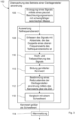
- Fig. 2 to 4 show process steps of three embodiments 100, 102, 104 of the method.
- Fig. 2 shows a first embodiment 100 of the method.
- vibrations arise in the plain bearing arrangement 12. These vibrations spread in the form of structure-borne sound in the plain bearing arrangement 12 and also in components adjacent to the plain bearing arrangement 12.
- the vibratable seismic mass 24 of the acceleration sensor 22 is excited to vibrate by the structure-borne sound.
- a signal 38 is generated by exciting the vibratable seismic mass 24 of the acceleration sensor 22 and a piezoelectric effect ( Fig. 1 ), which characterizes the vibration excitation associated with the plain bearing arrangement 12.
- the memory 20 and the computer program code stored therein are configured in cooperation with the processor 18 to process the signal 38 of the acceleration sensor 22 only in a partial frequency range 40 containing the resonance frequency 26 (see also Fig. 5 ) to be evaluated.
- the sub-frequency range 40 is limited by an upper frequency value 42 and a lower frequency value 44.
- the signal 38 of the acceleration sensor 22 is recorded over time and at a sampling rate that preferably corresponds to at least twice the upper frequency value 42. Because the sampling rate corresponds to twice the upper frequency value 42 of the partial frequency range 40 to be evaluated, the signal 38 is limited to the upper frequency value 42 for the evaluation.
- an averaged characteristic value is formed from the recorded partial frequency range 40 in method step 110.
- Various mathematical methods which were mentioned at the beginning, are available for forming an averaged characteristic value, for example the root mean square of the signal 38 of the sensor 14.
- a friction state of the plain bearing arrangement 12 can be concluded in method step 112. Starting from a hydrodynamic friction state, a friction state characterized by mixed friction is concluded if the characteristic value increases over time.
- a warning message 114 is preferably issued, which can be displayed, for example, by means of the display device 28, so that, for example, maintenance can be carried out on the plain bearing arrangement 12.
- a warning message 114 is preferably issued, which can be displayed, for example, by means of the display device 28, so that, for example, maintenance can be carried out on the plain bearing arrangement 12.
- plain bearing arrangements 12 of offshore wind turbines it is thus possible for plain bearing arrangements 12 of offshore wind turbines to be maintained according to their operating state.
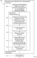
- Fig. 3 schematically depicts a second embodiment 102 of the method.
- the signal 38 is Fig.2 in a method step 108 with a sampling rate and then filtered in a method step 116 by means of a high-pass filter and by means of a low-pass filter.
- a cutoff frequency of the high-pass filter can correspond to the lower frequency value 44 of the partial frequency range 40 and a cutoff frequency of the low-pass filter can correspond to the upper frequency value 42 of the partial frequency range 40.
- the signal 38 is thus limited to the partial frequency range 40 to be evaluated.
- Fig. 3 a further variant is implemented in which, after the averaged characteristic value has been formed in method step 110, an optional method step 118 is carried out in addition to method step 112 or as part of it.
- the characteristic value is compared with a threshold value for mixed friction, so that, starting from a hydrodynamic friction state, a friction state characterized by mixed friction is concluded if the characteristic value increases over time and exceeds the predetermined threshold value. If mixed friction is detected or mixed friction is concluded, a warning message 114 can preferably be issued.
- the previously defined and stored threshold value can be based on calculations, tests or empirical values.
- Fig. 4 schematically depicts a third embodiment 104 of the method.
- the third embodiment 104 for example, no high/low pass filtering according to the second embodiment 102 is carried out, but rather according to the Acquiring the signal 38 with a sampling rate in method step 108, in a subsequent method step 120 the acquired signal 38 is Fourier transformed (see also Fig. 5 ) and then only evaluated in the partial frequency range 40.
- method step 112 of determining the friction state is carried out, in particular again optionally based on a threshold value comparison according to method step 118. Again, a warning message can be issued if the characteristic value increases over time and exceeds the predetermined threshold value.
- the friction state is therefore monitored over time in all process variants.
- a warning message 114 can be issued if mixed friction is detected.
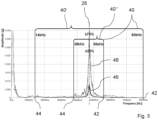
- Fig. 5 is an exemplary graphical representation of two Fourier-transformed signals 46, 48 of a single-axis acceleration sensor 22 with a resonance frequency 26 of 47 kHz under different friction conditions.
- a first Fourier-transformed signal 46 with a lower amplitude (shown as a black line) represents a hydrodynamic friction condition
- a second Fourier-transformed signal 48 with a larger amplitude (shown as a gray line) represents a friction condition with mixed friction.
- the second Fourier-transformed signal 48 has a significantly greater amplitude in the range of the resonance frequency 26 in the case of mixed friction than that of the first Fourier-transformed signal 46 in the case of hydrodynamic friction.
- the acceleration sensor 22 is The area of resonance frequency 26, i.e. at the highest sensitivity, is most strongly excited, and the mixed friction state can thus be detected starting from a hydrodynamic friction state.
- Fig. 5 two alternative sub-frequency ranges 40', 40'' containing the resonance frequency 26 are shown.
- the upper frequency value 42 is 1.7 times the resonance frequency 26 and the lower frequency value 44 is 0.3 times the resonance frequency 26.
- the upper frequency value 42 is 1.2 times the resonance frequency 26 and the lower frequency value 44 is 0.8 times the resonance frequency 26.
- Different partial frequency ranges 40 are to be selected depending on the design of the acceleration sensor 22. The smaller the partial frequency range 40 to be evaluated, the smaller the amount of data to be evaluated.
- the resonance frequency 26 of the acceleration sensor 22 coupled to the plain bearing location/arrangement 12 and the nature of the friction conditions in the range of the resonance frequency 26 are not known, then the partial frequency range 40 to be advantageously evaluated and the resonance frequency 26 of the acceleration sensor 22 in the installation situation can be in one experiment and by means of Fourier transformation.
Landscapes
- Physics & Mathematics (AREA)
- General Physics & Mathematics (AREA)
- Engineering & Computer Science (AREA)
- General Engineering & Computer Science (AREA)
- Mechanical Engineering (AREA)
- Chemical & Material Sciences (AREA)
- Analytical Chemistry (AREA)
- Acoustics & Sound (AREA)
- Testing Of Devices, Machine Parts, Or Other Structures Thereof (AREA)
- Measurement Of Mechanical Vibrations Or Ultrasonic Waves (AREA)
Claims (14)
- Procédé (100, 102, 104) de surveillance du fonctionnement d'un point/ensemble de palier lisse (12) au moyen d'un capteur (14), dans lequel un signal (38) est généré par le capteur (14), lequel signal (38) caractérise (106) une excitation vibratoire associée au point/ensemble de palier lisse (12), caractérisé en ce que le capteur (14) est un capteur d'accélération piézoélectrique (22) et en ce que le capteur d'accélération piézoélectrique (22) présente une masse sismique (24) capable d'osciller et présente en conséquence une fréquence de résonance (26) et en ce que la fréquence de résonance (26) se situe dans une plage de 20 à 70 kHz dans une situation de montage du capteur (14), et en ce que le signal (38) du capteur d'accélération (22) ne se situe que dans une plage de fréquences partielle (40, 40', 40") comportant la fréquence de résonance (26) qui est délimitée par une valeur de fréquence supérieure (42) et une valeur de fréquence inférieure (44), et en ce que le signal (38) du capteur d'accélération (22) est acquis dans le temps et avec une vitesse d'échantillonnage qui correspond au moins au double de la valeur de fréquence supérieure (42) (108), et en ce qu'une valeur caractéristique moyenne est formée (110) à partir du signal (38) du capteur d'accélération (22) dans cette plage de fréquences partielle (40, 40', 40"), et en ce qu'à l'aide de la valeur caractéristique, on conclut (112) à un état de frottement du point/ensemble de palier lisse, et en ce qu'en partant d'un état de frottement hydrodynamique, on conclut à un état de frottement marqué par un frottement mixte, lorsque la valeur caractéristique augmente au fil du temps.
- Procédé (100, 102, 104) selon la revendication 1, caractérisé en ce que la fréquence de résonance (26) se situe dans une plage de 20 à 50 kHz, en particulier de 20 à 40 kHz, dans la situation de montage du capteur (14).
- Procédé (100, 102, 104) selon l'une quelconque des revendications 1 ou 2, caractérisé en ce que la valeur de fréquence supérieure (42) est au plus égale à 1,2 fois ou au plus égale à 1,3 fois ou au plus égale à 1,4 fois ou au plus égale à 1,5 fois ou au plus égale à 1,6 fois ou au plus égale à 1,7 fois la fréquence de résonance (26).
- Procédé (100, 102, 104) selon l'une quelconque des revendications précédentes, caractérisé en ce que la valeur de fréquence inférieure (44) est au moins égale à 0,8 fois ou au moins égale à 0,7 fois ou au moins égale à 0,6 fois ou au moins égale à 0,5 fois ou au moins égale à 0,4 fois ou au moins égale à 0,3 fois la fréquence de résonance (26).
- Procédé (100, 102, 104) selon l'une quelconque des revendications précédentes, caractérisé en ce que la valeur caractéristique est une moyenne statistique, notamment la moyenne quadratique, la valeur maximale, la valeur pic-vallée, la variance, la valeur de kurtosis, une valeur de crête.
- Procédé (102, 104) selon l'une quelconque des revendications précédentes, caractérisé en ce qu'en partant d'un état de frottement hydrodynamique, on conclut à un état de frottement marqué par un frottement mixte lorsque la valeur caractéristique dépasse (118), au fil du temps, une valeur seuil prédéfinie ou pouvant être prédéfinie.
- Procédé (102) selon l'une quelconque des revendications précédentes, caractérisé en ce que le signal (38) du capteur d'accélération (22) est filtré (116) au moyen d'un filtre passe-haut et en particulier en outre au moyen d'un filtre passe-bas.
- Procédé (102) selon la revendication 7, caractérisé en ce qu'une fréquence de coupure du filtre passe-haut correspond à la valeur de fréquence inférieure (44) de la plage de fréquences partielle (40, 40', 40") et/ou en ce qu'une fréquence de coupure du filtre passe-bas correspond à la valeur de fréquence supérieure (42) de la plage de fréquences partielle (40, 40', 40").
- Procédé (104) selon l'une quelconque des revendications 1 à 6, caractérisé en ce qu'un signal (38) du capteur d'accélération (22) subit une transformation de Fourier (120) et n'est ensuite évalué que dans la plage de fréquences partielle (40, 40', 40").
- Dispositif (10) de surveillance du fonctionnement d'un point/ensemble de palier lisse (12), comprenant un capteur (14) qui peut être disposé ou est disposé de manière couplée mécaniquement au point/ensemble de palier lisse (12), dans lequel un signal (38) est généré par le capteur (14), lequel signal (38) caractérise (106) une excitation vibratoire associée au point/ensemble de palier lisse (12), et comprenant en outre un système d'évaluation électronique (16) avec un processeur (18) et une mémoire (20) avec un code de programme informatique qui y est enregistré, caractérisé en ce que le capteur (14) est un capteur d'accélération piézoélectrique (22) et en ce que le capteur d'accélération piézoélectrique (22) présente une masse sismique vibrante (24) et présente par conséquent une fréquence de résonance (26), dans lequel la masse sismique (24) est excitée pour osciller par le bruit de structure du point/ensemble de palier lisse (12) et le signal (38) est ainsi généré (106), dans lequel la fréquence de résonance (26) se situe dans une plage de 20 à 70 kHz dans une situation de montage du capteur (14), et en ce que la mémoire (20) et le code de programme informatique sont configurés, en coopération avec le processeur (18), pour évaluer le signal (38) du capteur d'accélération (22) uniquement dans une plage de fréquences partielle (40, 40', 40") comportant la fréquence de résonance (26), qui est délimitée par une valeur de fréquence supérieure (42) et une valeur de fréquence inférieure (44), et sont en outre configurés pour acquérir le signal (38) du capteur d'accélération (22) dans le temps et à une vitesse d'échantillonnage qui correspond au moins au double de la valeur de fréquence supérieure (42) (108), et sont en outre configurés pour former (110) une valeur caractéristique moyenne à partir du signal (38) du capteur d'accélération (22) dans cette plage de fréquences partielle (40, 40', 40") et pour conclure (112), à l'aide de la valeur caractéristique, à un état de frottement du point/ensemble de palier lisse, et sont en outre configurés pour conclure, en partant d'un état de frottement hydrodynamique, à un état de frottement marqué par un frottement mixte, lorsque la valeur caractéristique augmente au fil du temps.
- Dispositif (10) selon la revendication 10, caractérisé en ce que le dispositif (10) comprend un filtre passe-haut et en particulier en outre un filtre passe-bas, et en ce que le signal (38) du capteur d'accélération (22) est filtré (116) au moyen du filtre passe-haut et en particulier en outre au moyen du filtre passe-bas (116).
- Dispositif (10) selon la revendication 11, caractérisé en ce qu'une fréquence de coupure du filtre passe-haut correspond à la valeur de fréquence inférieure (44) de la plage de fréquences partielle (40, 40', 40") et/ou en ce qu'une fréquence de coupure du filtre passe-bas correspond à la valeur de fréquence supérieure (42) de la plage de fréquences partielle (40, 40', 40").
- Dispositif (10) selon la revendication 10, caractérisé en ce que le système d'évaluation électronique (16) est réalisé pour transformer en fourier (120) le signal (38) du capteur d'accélération (22) et pour ne l'évaluer ensuite que dans la plage de fréquences partielle (40, 40', 40").
- Point/ensemble de palier lisse (12), lequel est couplé mécaniquement à un dispositif (10) de surveillance du fonctionnement du point/ensemble de palier lisse (12) selon au moins l'une quelconque des revendications 10 à 13, de sorte que le bruit de structure généré par le point/ensemble de palier lisse (12) peut être transmis au dispositif (10) et au capteur d'accélération piézoélectrique (22) de celui-ci et peut être surveillé par le dispositif (10).
Applications Claiming Priority (2)
| Application Number | Priority Date | Filing Date | Title |
|---|---|---|---|
| DE102022121294.7A DE102022121294A1 (de) | 2022-08-23 | 2022-08-23 | Verfahren und Vorrichtung zur Überwachung des Betriebs einer Gleitlagerstelle/-anordnung und eine entsprechende Gleitlagerstelle/-anordnung |
| PCT/EP2023/072718 WO2024041975A1 (fr) | 2022-08-23 | 2023-08-17 | Procédé et dispositif de surveillance du fonctionnement d'un point/agencement de palier coulissant et point/agencement de palier coulissant correspondant |
Publications (2)
| Publication Number | Publication Date |
|---|---|
| EP4359751A1 EP4359751A1 (fr) | 2024-05-01 |
| EP4359751B1 true EP4359751B1 (fr) | 2024-10-16 |
Family
ID=87797653
Family Applications (1)
| Application Number | Title | Priority Date | Filing Date |
|---|---|---|---|
| EP23758598.9A Active EP4359751B1 (fr) | 2022-08-23 | 2023-08-17 | Procédé et dispositif de surveillance du fonctionnement d'un point/agencement de palier coulissant et point/agencement de palier coulissant correspondant |
Country Status (4)
| Country | Link |
|---|---|
| EP (1) | EP4359751B1 (fr) |
| DE (1) | DE102022121294A1 (fr) |
| ES (1) | ES2996945T3 (fr) |
| WO (1) | WO2024041975A1 (fr) |
Families Citing this family (1)
| Publication number | Priority date | Publication date | Assignee | Title |
|---|---|---|---|---|
| DE102023126529B3 (de) * | 2023-09-28 | 2025-03-27 | Ks Gleitlager Gmbh | Verfahren und Vorrichtung zum Bestimmen eines Verschleißzustands einer Gleitlageranordnung |
Family Cites Families (7)
| Publication number | Priority date | Publication date | Assignee | Title |
|---|---|---|---|---|
| EP2805072A1 (fr) | 2012-04-19 | 2014-11-26 | Siemens Aktiengesellschaft | Procédé et dispositif de mesure pour contrôler des états de fonctionnement d'un palier lisse |
| CN105531576A (zh) * | 2013-09-12 | 2016-04-27 | 西门子公司 | 用于监测技术上的装置、如机器或设备的方法和布置 |
| US9841329B2 (en) | 2015-06-08 | 2017-12-12 | Pioner Engineering Company | Strain gage based system and method for failure detection of a fluid film bearing |
| DE102017119543A1 (de) | 2017-08-25 | 2019-02-28 | Rolls-Royce Deutschland Ltd & Co Kg | Verfahren und Vorrichtung zur Überwachung eines Gleitlagers |
| DE102017223418B4 (de) | 2017-12-20 | 2023-05-25 | Zf Friedrichshafen Ag | Modellbasiertes Verfahren und System zur Zustandsüberwachung eines Gleitlagers, insbesondere für Windkraftanlagen |
| AT521572B1 (de) * | 2018-08-29 | 2020-07-15 | Miba Gleitlager Austria Gmbh | Gleitlageranordnung |
| DE102018123571A1 (de) | 2018-09-25 | 2020-03-26 | Rolls-Royce Deutschland Ltd & Co Kg | Verfahren und Vorrichtung zur Schätzung des Verschleißzustandes eines Gleitlagers |
-
2022
- 2022-08-23 DE DE102022121294.7A patent/DE102022121294A1/de not_active Ceased
-
2023
- 2023-08-17 EP EP23758598.9A patent/EP4359751B1/fr active Active
- 2023-08-17 WO PCT/EP2023/072718 patent/WO2024041975A1/fr not_active Ceased
- 2023-08-17 ES ES23758598T patent/ES2996945T3/es active Active
Also Published As
| Publication number | Publication date |
|---|---|
| WO2024041975A1 (fr) | 2024-02-29 |
| ES2996945T3 (en) | 2025-02-13 |
| DE102022121294A1 (de) | 2024-02-29 |
| EP4359751A1 (fr) | 2024-05-01 |
Similar Documents
| Publication | Publication Date | Title |
|---|---|---|
| DE69526507T2 (de) | Verfahren zum bestimmen von resonanzinformation | |
| DE69937737T2 (de) | Beurteilung des zustands eines lagers | |
| EP2316009B1 (fr) | Procédé et dispositif permettant de déterminer et de surveiller l'état d'un roulement | |
| EP2623949A1 (fr) | Dispositif de surveillance d'état et procédé de surveillance d'état de composants mécaniques rotatifs | |
| DE19938722B4 (de) | Verfahren und Vorrichtung zur Analyse von Wälzlagern in Maschinen | |
| DE102015216468B4 (de) | Verfahren und Anordnung zur Zustandsüberwachung eines Lagers, das ein Planetenrad eines Planetengetriebes auf einem Planetenträger lagert | |
| EP2549257B1 (fr) | Procédé de détection de dommages sur des engrenages | |
| WO2015036021A1 (fr) | Procédé et système de surveillance d'un équipement technique tel qu'une machine ou une installation | |
| WO2011032948A1 (fr) | Procédé et dispositif pour la surveillance du comportement en déplacement d'un véhicule ferroviaire | |
| EP2737292B1 (fr) | Procédé et dispositif pour déterminer et/ou surveiller l'état d'un roulement | |
| WO2013156068A1 (fr) | Procédé et dispositif de mesure pour contrôler des états de fonctionnement d'un palier lisse | |
| WO2013060420A2 (fr) | Procédé permettant de déterminer un dommage mécanique subi par une pale de rotor d'éolienne | |
| DE3812904A1 (de) | Blockiergeschuetzte bremsanlage mit ueberwachtem drehzahlfuehler und verfahren zum messen der drehzahl in einer solchen bremsanlage | |
| EP1616163B1 (fr) | Procede de detection d'evenements de bruit de structure dans un palier a roulement | |
| DE19702234A1 (de) | Verfahren zur Überwachung und Qualitätsbeurteilung von sich bewegenden und/oder rotierenden Maschinenteilen insbesondere von Maschinenlagern | |
| DE102011055523A1 (de) | Verfahren und Vorrichtung zur Schwingungsanalyse von Anlagen oder Maschinenelementen | |
| WO2003071243A1 (fr) | Procede et dispositif pour la detection d'une action mecanique impulsionnelle sur une partie d'installation | |
| EP4359751B1 (fr) | Procédé et dispositif de surveillance du fonctionnement d'un point/agencement de palier coulissant et point/agencement de palier coulissant correspondant | |
| DE102016202340A1 (de) | Messvorrichtung und Messverfahren | |
| EP2844973B1 (fr) | Procédé de surveillance de déterioration d'un arbre | |
| EP2464956A1 (fr) | Procédé de détection précoce de dommages dans une transmission de véhicule automobile | |
| DE102010005525B4 (de) | Verfahren zur Zustandsüberwachung einer Maschine und Überwachungseinrichtung hierfür | |
| EP1415132B1 (fr) | Evaluation spectrale d'un objet d'essai | |
| EP2110649B1 (fr) | Capteur pour surveiller des éléments mécaniques de construction | |
| EP3388810B1 (fr) | Procédé et dispositif de détection de balancement |
Legal Events
| Date | Code | Title | Description |
|---|---|---|---|
| STAA | Information on the status of an ep patent application or granted ep patent |
Free format text: STATUS: UNKNOWN |
|
| STAA | Information on the status of an ep patent application or granted ep patent |
Free format text: STATUS: THE INTERNATIONAL PUBLICATION HAS BEEN MADE |
|
| PUAI | Public reference made under article 153(3) epc to a published international application that has entered the european phase |
Free format text: ORIGINAL CODE: 0009012 |
|
| STAA | Information on the status of an ep patent application or granted ep patent |
Free format text: STATUS: REQUEST FOR EXAMINATION WAS MADE |
|
| 17P | Request for examination filed |
Effective date: 20240124 |
|
| AK | Designated contracting states |
Kind code of ref document: A1 Designated state(s): AL AT BE BG CH CY CZ DE DK EE ES FI FR GB GR HR HU IE IS IT LI LT LU LV MC ME MK MT NL NO PL PT RO RS SE SI SK SM TR |
|
| GRAP | Despatch of communication of intention to grant a patent |
Free format text: ORIGINAL CODE: EPIDOSNIGR1 |
|
| STAA | Information on the status of an ep patent application or granted ep patent |
Free format text: STATUS: GRANT OF PATENT IS INTENDED |
|
| INTG | Intention to grant announced |
Effective date: 20240606 |
|
| GRAS | Grant fee paid |
Free format text: ORIGINAL CODE: EPIDOSNIGR3 |
|
| GRAA | (expected) grant |
Free format text: ORIGINAL CODE: 0009210 |
|
| STAA | Information on the status of an ep patent application or granted ep patent |
Free format text: STATUS: THE PATENT HAS BEEN GRANTED |
|
| DAV | Request for validation of the european patent (deleted) | ||
| DAX | Request for extension of the european patent (deleted) | ||
| P01 | Opt-out of the competence of the unified patent court (upc) registered |
Free format text: CASE NUMBER: APP_50118/2024 Effective date: 20240904 |
|
| AK | Designated contracting states |
Kind code of ref document: B1 Designated state(s): AL AT BE BG CH CY CZ DE DK EE ES FI FR GB GR HR HU IE IS IT LI LT LU LV MC ME MK MT NL NO PL PT RO RS SE SI SK SM TR |
|
| REG | Reference to a national code |
Ref country code: GB Ref legal event code: FG4D Free format text: NOT ENGLISH |
|
| REG | Reference to a national code |
Ref country code: CH Ref legal event code: EP |
|
| REG | Reference to a national code |
Ref country code: IE Ref legal event code: FG4D Free format text: LANGUAGE OF EP DOCUMENT: GERMAN |
|
| REG | Reference to a national code |
Ref country code: DE Ref legal event code: R096 Ref document number: 502023000218 Country of ref document: DE |
|
| REG | Reference to a national code |
Ref country code: LT Ref legal event code: MG9D |
|
| REG | Reference to a national code |
Ref country code: ES Ref legal event code: FG2A Ref document number: 2996945 Country of ref document: ES Kind code of ref document: T3 Effective date: 20250213 |
|
| REG | Reference to a national code |
Ref country code: NL Ref legal event code: MP Effective date: 20241016 |
|
| PG25 | Lapsed in a contracting state [announced via postgrant information from national office to epo] |
Ref country code: NL Free format text: LAPSE BECAUSE OF FAILURE TO SUBMIT A TRANSLATION OF THE DESCRIPTION OR TO PAY THE FEE WITHIN THE PRESCRIBED TIME-LIMIT Effective date: 20241016 |
|
| PG25 | Lapsed in a contracting state [announced via postgrant information from national office to epo] |
Ref country code: NL Free format text: LAPSE BECAUSE OF FAILURE TO SUBMIT A TRANSLATION OF THE DESCRIPTION OR TO PAY THE FEE WITHIN THE PRESCRIBED TIME-LIMIT Effective date: 20241016 |
|
| PG25 | Lapsed in a contracting state [announced via postgrant information from national office to epo] |
Ref country code: HR Free format text: LAPSE BECAUSE OF FAILURE TO SUBMIT A TRANSLATION OF THE DESCRIPTION OR TO PAY THE FEE WITHIN THE PRESCRIBED TIME-LIMIT Effective date: 20241016 Ref country code: IS Free format text: LAPSE BECAUSE OF FAILURE TO SUBMIT A TRANSLATION OF THE DESCRIPTION OR TO PAY THE FEE WITHIN THE PRESCRIBED TIME-LIMIT Effective date: 20250216 Ref country code: PT Free format text: LAPSE BECAUSE OF FAILURE TO SUBMIT A TRANSLATION OF THE DESCRIPTION OR TO PAY THE FEE WITHIN THE PRESCRIBED TIME-LIMIT Effective date: 20250217 |
|
| PG25 | Lapsed in a contracting state [announced via postgrant information from national office to epo] |
Ref country code: FI Free format text: LAPSE BECAUSE OF FAILURE TO SUBMIT A TRANSLATION OF THE DESCRIPTION OR TO PAY THE FEE WITHIN THE PRESCRIBED TIME-LIMIT Effective date: 20241016 |
|
| PG25 | Lapsed in a contracting state [announced via postgrant information from national office to epo] |
Ref country code: BG Free format text: LAPSE BECAUSE OF FAILURE TO SUBMIT A TRANSLATION OF THE DESCRIPTION OR TO PAY THE FEE WITHIN THE PRESCRIBED TIME-LIMIT Effective date: 20241016 |
|
| PG25 | Lapsed in a contracting state [announced via postgrant information from national office to epo] |
Ref country code: NO Free format text: LAPSE BECAUSE OF FAILURE TO SUBMIT A TRANSLATION OF THE DESCRIPTION OR TO PAY THE FEE WITHIN THE PRESCRIBED TIME-LIMIT Effective date: 20250116 |
|
| PG25 | Lapsed in a contracting state [announced via postgrant information from national office to epo] |
Ref country code: LV Free format text: LAPSE BECAUSE OF FAILURE TO SUBMIT A TRANSLATION OF THE DESCRIPTION OR TO PAY THE FEE WITHIN THE PRESCRIBED TIME-LIMIT Effective date: 20241016 Ref country code: GR Free format text: LAPSE BECAUSE OF FAILURE TO SUBMIT A TRANSLATION OF THE DESCRIPTION OR TO PAY THE FEE WITHIN THE PRESCRIBED TIME-LIMIT Effective date: 20250117 |
|
| PG25 | Lapsed in a contracting state [announced via postgrant information from national office to epo] |
Ref country code: PL Free format text: LAPSE BECAUSE OF FAILURE TO SUBMIT A TRANSLATION OF THE DESCRIPTION OR TO PAY THE FEE WITHIN THE PRESCRIBED TIME-LIMIT Effective date: 20241016 |
|
| PG25 | Lapsed in a contracting state [announced via postgrant information from national office to epo] |
Ref country code: RS Free format text: LAPSE BECAUSE OF FAILURE TO SUBMIT A TRANSLATION OF THE DESCRIPTION OR TO PAY THE FEE WITHIN THE PRESCRIBED TIME-LIMIT Effective date: 20250116 |
|
| PG25 | Lapsed in a contracting state [announced via postgrant information from national office to epo] |
Ref country code: SM Free format text: LAPSE BECAUSE OF FAILURE TO SUBMIT A TRANSLATION OF THE DESCRIPTION OR TO PAY THE FEE WITHIN THE PRESCRIBED TIME-LIMIT Effective date: 20241016 |
|
| PG25 | Lapsed in a contracting state [announced via postgrant information from national office to epo] |
Ref country code: DK Free format text: LAPSE BECAUSE OF FAILURE TO SUBMIT A TRANSLATION OF THE DESCRIPTION OR TO PAY THE FEE WITHIN THE PRESCRIBED TIME-LIMIT Effective date: 20241016 |
|
| REG | Reference to a national code |
Ref country code: DE Ref legal event code: R097 Ref document number: 502023000218 Country of ref document: DE |
|
| PG25 | Lapsed in a contracting state [announced via postgrant information from national office to epo] |
Ref country code: EE Free format text: LAPSE BECAUSE OF FAILURE TO SUBMIT A TRANSLATION OF THE DESCRIPTION OR TO PAY THE FEE WITHIN THE PRESCRIBED TIME-LIMIT Effective date: 20241016 |
|
| PG25 | Lapsed in a contracting state [announced via postgrant information from national office to epo] |
Ref country code: RO Free format text: LAPSE BECAUSE OF FAILURE TO SUBMIT A TRANSLATION OF THE DESCRIPTION OR TO PAY THE FEE WITHIN THE PRESCRIBED TIME-LIMIT Effective date: 20241016 |
|
| PG25 | Lapsed in a contracting state [announced via postgrant information from national office to epo] |
Ref country code: SK Free format text: LAPSE BECAUSE OF FAILURE TO SUBMIT A TRANSLATION OF THE DESCRIPTION OR TO PAY THE FEE WITHIN THE PRESCRIBED TIME-LIMIT Effective date: 20241016 |
|
| PG25 | Lapsed in a contracting state [announced via postgrant information from national office to epo] |
Ref country code: CZ Free format text: LAPSE BECAUSE OF FAILURE TO SUBMIT A TRANSLATION OF THE DESCRIPTION OR TO PAY THE FEE WITHIN THE PRESCRIBED TIME-LIMIT Effective date: 20241016 |
|
| PG25 | Lapsed in a contracting state [announced via postgrant information from national office to epo] |
Ref country code: IT Free format text: LAPSE BECAUSE OF FAILURE TO SUBMIT A TRANSLATION OF THE DESCRIPTION OR TO PAY THE FEE WITHIN THE PRESCRIBED TIME-LIMIT Effective date: 20241016 |
|
| PLBE | No opposition filed within time limit |
Free format text: ORIGINAL CODE: 0009261 |
|
| STAA | Information on the status of an ep patent application or granted ep patent |
Free format text: STATUS: NO OPPOSITION FILED WITHIN TIME LIMIT |
|
| PG25 | Lapsed in a contracting state [announced via postgrant information from national office to epo] |
Ref country code: SE Free format text: LAPSE BECAUSE OF FAILURE TO SUBMIT A TRANSLATION OF THE DESCRIPTION OR TO PAY THE FEE WITHIN THE PRESCRIBED TIME-LIMIT Effective date: 20241016 |
|
| 26N | No opposition filed |
Effective date: 20250717 |
|
| PGFP | Annual fee paid to national office [announced via postgrant information from national office to epo] |
Ref country code: ES Payment date: 20250917 Year of fee payment: 3 |
|
| PGFP | Annual fee paid to national office [announced via postgrant information from national office to epo] |
Ref country code: BE Payment date: 20250820 Year of fee payment: 3 |
|
| PGFP | Annual fee paid to national office [announced via postgrant information from national office to epo] |
Ref country code: AT Payment date: 20251020 Year of fee payment: 3 |
|
| PGFP | Annual fee paid to national office [announced via postgrant information from national office to epo] |
Ref country code: DE Payment date: 20251021 Year of fee payment: 3 |
|
| PG25 | Lapsed in a contracting state [announced via postgrant information from national office to epo] |
Ref country code: MC Free format text: LAPSE BECAUSE OF FAILURE TO SUBMIT A TRANSLATION OF THE DESCRIPTION OR TO PAY THE FEE WITHIN THE PRESCRIBED TIME-LIMIT Effective date: 20241016 |
|
| PG25 | Lapsed in a contracting state [announced via postgrant information from national office to epo] |
Ref country code: LU Free format text: LAPSE BECAUSE OF NON-PAYMENT OF DUE FEES Effective date: 20250817 |