EP4359751B1 - Method and device for monitoring the operation of a sliding bearing point/arrangement and a corresponding sliding bearing point/arrangement - Google Patents
Method and device for monitoring the operation of a sliding bearing point/arrangement and a corresponding sliding bearing point/arrangement Download PDFInfo
- Publication number
- EP4359751B1 EP4359751B1 EP23758598.9A EP23758598A EP4359751B1 EP 4359751 B1 EP4359751 B1 EP 4359751B1 EP 23758598 A EP23758598 A EP 23758598A EP 4359751 B1 EP4359751 B1 EP 4359751B1
- Authority
- EP
- European Patent Office
- Prior art keywords
- value
- signal
- acceleration sensor
- arrangement
- plain bearing
- Prior art date
- Legal status (The legal status is an assumption and is not a legal conclusion. Google has not performed a legal analysis and makes no representation as to the accuracy of the status listed.)
- Active
Links
Images


Classifications
-
- G—PHYSICS
- G01—MEASURING; TESTING
- G01M—TESTING STATIC OR DYNAMIC BALANCE OF MACHINES OR STRUCTURES; TESTING OF STRUCTURES OR APPARATUS, NOT OTHERWISE PROVIDED FOR
- G01M13/00—Testing of machine parts
- G01M13/04—Bearings
- G01M13/045—Acoustic or vibration analysis
-
- F—MECHANICAL ENGINEERING; LIGHTING; HEATING; WEAPONS; BLASTING
- F16—ENGINEERING ELEMENTS AND UNITS; GENERAL MEASURES FOR PRODUCING AND MAINTAINING EFFECTIVE FUNCTIONING OF MACHINES OR INSTALLATIONS; THERMAL INSULATION IN GENERAL
- F16C—SHAFTS; FLEXIBLE SHAFTS; ELEMENTS OR CRANKSHAFT MECHANISMS; ROTARY BODIES OTHER THAN GEARING ELEMENTS; BEARINGS
- F16C17/00—Sliding-contact bearings for exclusively rotary movement
- F16C17/12—Sliding-contact bearings for exclusively rotary movement characterised by features not related to the direction of the load
- F16C17/24—Sliding-contact bearings for exclusively rotary movement characterised by features not related to the direction of the load with devices affected by abnormal or undesired positions, e.g. for preventing overheating, for safety
-
- G—PHYSICS
- G01—MEASURING; TESTING
- G01H—MEASUREMENT OF MECHANICAL VIBRATIONS OR ULTRASONIC, SONIC OR INFRASONIC WAVES
- G01H1/00—Measuring characteristics of vibrations in solids by using direct conduction to the detector
- G01H1/003—Measuring characteristics of vibrations in solids by using direct conduction to the detector of rotating machines
-
- G—PHYSICS
- G01—MEASURING; TESTING
- G01H—MEASUREMENT OF MECHANICAL VIBRATIONS OR ULTRASONIC, SONIC OR INFRASONIC WAVES
- G01H11/00—Measuring mechanical vibrations or ultrasonic, sonic or infrasonic waves by detecting changes in electric or magnetic properties
- G01H11/06—Measuring mechanical vibrations or ultrasonic, sonic or infrasonic waves by detecting changes in electric or magnetic properties by electric means
- G01H11/08—Measuring mechanical vibrations or ultrasonic, sonic or infrasonic waves by detecting changes in electric or magnetic properties by electric means using piezoelectric devices
-
- G—PHYSICS
- G01—MEASURING; TESTING
- G01L—MEASURING FORCE, STRESS, TORQUE, WORK, MECHANICAL POWER, MECHANICAL EFFICIENCY, OR FLUID PRESSURE
- G01L5/00—Apparatus for, or methods of, measuring force, work, mechanical power, or torque, specially adapted for specific purposes
- G01L5/0009—Force sensors associated with a bearing
- G01L5/0019—Force sensors associated with a bearing by using strain gages, piezoelectric, piezo-resistive or other ohmic-resistance based sensors
-
- F—MECHANICAL ENGINEERING; LIGHTING; HEATING; WEAPONS; BLASTING
- F16—ENGINEERING ELEMENTS AND UNITS; GENERAL MEASURES FOR PRODUCING AND MAINTAINING EFFECTIVE FUNCTIONING OF MACHINES OR INSTALLATIONS; THERMAL INSULATION IN GENERAL
- F16C—SHAFTS; FLEXIBLE SHAFTS; ELEMENTS OR CRANKSHAFT MECHANISMS; ROTARY BODIES OTHER THAN GEARING ELEMENTS; BEARINGS
- F16C2233/00—Monitoring condition, e.g. temperature, load, vibration
Definitions
- the invention relates to a method and a device for monitoring the operation of a plain bearing point/arrangement by means of a sensor, wherein the sensor generates a signal which characterizes a vibration excitation associated with the plain bearing point/arrangement.
- the invention further relates to a plain bearing point/arrangement which is mechanically coupled to the device according to the invention.
- Plain bearings are used in various areas of industry. Plain bearings are also used in large machines, such as wind turbines. Monitoring plain bearings is used to detect faulty operating conditions that can lead to damage or downtime of the entire machine. Furthermore, monitoring plain bearings can be used to optimize maintenance intervals.
- a component for example a shaft or a pin
- a sliding layer, a sliding coating or a lubricating film is usually formed between the components or on at least one of the components.
- a bush-shaped plain bearing element with a sliding layer can be provided between the components or for mounting one of the components.
- a plain bearing point/arrangement can comprise a housing, a plain bearing element typically firmly inserted therein and a shaft part mounted therein.
- a plain bearing point/arrangement can also comprise a machine part, in particular a gear, as the first component, which is rotatably mounted on a shaft as the second component.
- the shaft can comprise a bush-shaped sliding element or a sliding coating for this purpose.
- a device and a method which, by recording measured values Characterize sound emissions in a plain bearing and classify an operating state of the plain bearing by calculating a characteristic value from these measured values.
- a sensor element that is mechanically coupled to the plain bearing is used to record measured values.
- the sensor element records sound emissions occurring in the plain bearing in a wide frequency range from 50 to 150 kHz. It is stated that the sensor element can be designed as an acceleration sensor or as a pressure sensor or as a strain gauge or as a piezoelectric sensor element.
- the sensor element is preferably designed as a micromechanical sensor, i.e. as a capacitive sensor that can include a seismic mass, for example.
- the US2016/0356657A1 A system and a method are known for determining the failure of a plain bearing by detecting and evaluating strain loads on the plain bearing housing.
- at least one strain sensor is arranged on the plain bearing housing.
- the strain sensor generates an electrically measurable output signal in response to changes in a Strain state of the bearing housing.
- the amplitudes of the strain frequencies of interest can be determined as a trend and correlated with the wear of the plain bearing.
- Possible strain sensors include a strain gauge with a metal foil, a piezoelectric strain gauge and a piezoresistive strain gauge.
- the use of a proximity sensor and an acceleration sensor is described as disadvantageous compared to the strain sensors used.
- the acceleration sensor in particular is disadvantageous in that it generates a signal that contains a large number of disturbing frequency noises. It is difficult to distinguish whether the frequency noises come from an intact or already damaged plain bearing using this measuring device.
- the present invention is based on the object of providing a simplified method for monitoring the operation of a plain bearing location/arrangement with a reduced amount of data acquisition and yet reliable data evaluation.
- vibrations arise in the plain bearing location/arrangement, which spread in the form of structure-borne sound in the plain bearing location/arrangement and also in adjacent components.
- the vibrating seismic mass of the piezoelectric acceleration sensor is excited to vibrate by the structure-borne noise generated during operation of the plain bearing point/arrangement.
- the piezoelectric effect is used to generate the sensor signal from the vibration of the seismic mass, which characterizes the vibration excitation associated with the plain bearing point/arrangement.
- the amplitude of the structure-borne noise is particularly dependent on the friction state of the plain bearing point/arrangement, i.e. hydrodynamic friction, mixed friction or, in particular, Solid friction.
- the acceleration sensor can be a single-, two- or three-axis seismic mass piezoelectric acceleration sensor.
- the acceleration sensor is designed using the vibrating seismic mass in such a way that its resonance frequency in the installation situation is in a range of 20 to 70 kHz.
- the resonance frequency of the acceleration sensor is sensor-specific, but also depends on the installation situation or the fastening of the acceleration sensor to the plain bearing location/arrangement, for example by screwing, gluing, magnetic arrangement, etc. If the resonance frequency of the acceleration sensor in its installation situation is not known, then it should be determined in advance.
- the signal of the acceleration sensor is evaluated in the partial frequency range containing the resonance frequency.
- the acceleration sensor is stimulated more strongly in the resonance range, whereby the signal from the acceleration sensor is amplified in the partial frequency range. This means that the acceleration sensor is evaluated in the range with the highest sensitivity, which leads to a high level of reliability of the method.
- the method according to the invention also makes it possible to record the structure-borne noise generated by mixed friction in plain bearings at low speeds (low sliding speeds, e.g. start-stop operation).
- the acceleration sensor signal can be evaluated up to the upper frequency value. If, for example, the sampling rate is limited to exactly twice the partial frequency range to be evaluated, the signal that can be evaluated is limited to the upper frequency value.
- the partial frequency range to be monitored is preferably independent of a bearing material, a rotational speed (sliding speed), a load and a lubricant as well as a lubricant temperature.
- a characteristic value is formed from the signal of the acceleration sensor in this partial frequency range. If the characteristic value increases over time, mixed friction can be concluded. A comparison with a stored reference value table is not absolutely necessary, which is considered advantageous.
- Real-time monitoring of the plain bearing point/arrangement during operation can be implemented in a simple manner. Mixed friction of the plain bearing point/arrangement can be reliably identified, and damage to the plain bearing point/arrangement can be prevented, for example by carrying out maintenance on the plain bearing point/arrangement at an early stage.
- the resonance frequency in the installation situation of the sensor is in a range of 20 to 50 kHz, especially 20 to 40 kHz. Because the range in which the resonance frequency lies is smaller, the partial frequency range to be evaluated can also be reduced. which means that a smaller amount of data is generated and needs to be evaluated.
- the upper frequency value is at most 1.2 times or at most 1.3 times or at most 1.4 times or at most 1.5 times or at most 1.6 times or at most 1.7 times the resonance frequency.
- the lower frequency value is at least 0.8 times or at least 0.7 times or at least 0.6 times or at least 0.5 times or at least 0.4 times or at least 0.3 times the resonance frequency.
- the characteristic value is a statistical mean, in particular the root mean square (RMS), the maximum value, the peak-valley value, the variance (distribution of the values around the mean), the kurtosis value (measure of the steepness), a peak value (ratio of the maximum value to the root mean square).
- RMS root mean square
- the characteristic value is easier to handle than the signal recorded by the acceleration sensor. By forming the characteristic value, disturbing signal parts and/or outliers in the signal of the acceleration sensor are compensated. Trends and developments of the characteristic value can be recorded over time.
- a friction state characterized by mixed friction is concluded if the characteristic value over time exceeds a specified or predeterminable threshold value. It is also conceivable that a threshold value for solid body friction can also be specified in the event that mixed friction is exceeded. A threshold value can ensure that mixed friction is reliably detected. It is also considered advantageous that mixed friction can be detected when the plain bearing point/arrangement is put into operation using the threshold value if the characteristic value formed exceeds the threshold value.
- the signal from the acceleration sensor is filtered using a high-pass filter and in particular additionally using a low-pass filter.
- the signal can be cleaned of sub-frequency ranges that are unnecessary for monitoring using the high-pass filter and in particular additionally using the low-pass filter before the characteristic value is formed.
- a cutoff frequency of the high-pass filter corresponds to the lower frequency value of the partial frequency range and/or that a cutoff frequency of the low-pass filter corresponds to the upper frequency value of the partial frequency range.
- the signal can be limited to the partial frequency range to be evaluated, so that a smaller amount of data is generated than if the unfiltered signal is evaluated. This results in lower costs and time savings for the measurement data acquisition and evaluation.
- a signal from the acceleration sensor is Fourier transformed and is then evaluated only in the partial frequency range.
- This Fourier transformation represents an alternative to filtering.
- the device comprises a high-pass filter and in particular additionally a low-pass filter, and that the signal of the acceleration sensor is filtered by means of the high-pass filter and in particular additionally by means of the low-pass filter.
- a high-pass filter and in particular the low-pass filter can be designed, for example, as electrical components.
- the memory and the computer program code can be configured as a high-pass filter and in particular as a low-pass filter in conjunction with the processor.
- a cutoff frequency of the high-pass filter corresponds to the lower frequency value of the sub-frequency range and/or that a cutoff frequency of the low-pass filter corresponds to the upper frequency value of the sub-frequency range.
- the electronic evaluation device is designed to evaluate the signal of the acceleration sensor and then evaluate it only in the partial frequency range.
- a further subject matter of the invention is a plain bearing point/arrangement which is mechanically coupled to a device according to the invention for monitoring the operation of the plain bearing point/arrangement, so that structure-borne sound generated by the plain bearing point/arrangement can be transmitted to the device and its piezoelectric acceleration sensor and monitored by the device.
- Fig. 1 shows a schematic of a device for monitoring the operation of a plain bearing point/arrangement 12, which is designated overall by the reference number 10.
- the device 10 comprises a sensor 14, an electrical evaluation device 16 with a processor 18 and a memory 20 with a computer program stored thereon.
- the sensor 14 is designed as a piezoelectric acceleration sensor 22 with an oscillating seismic mass 24.
- the acceleration sensor 22 is designed by means of the oscillating seismic mass 24 such that a resonance frequency 26 of the acceleration sensor 22 in an installation situation is in a range of 20 to 70 kHz.
- the evaluation device 16 is connected - wired or wirelessly - to the acceleration sensor 22 and can, for example, also be connected to an external display device 28 - e.g. mobile device, indicator light, screen - which is also spatially spaced from the acceleration sensor 22.
- the plain bearing arrangement 12 which is only indicated schematically, comprises, for example, a plain bearing housing 30 and a shaft 32 mounted in the plain bearing housing 30, with further sliding elements or sliding coatings that may act between the components not being shown. Between the plain bearing housing 30 and the shaft 32, a lubricating film 34 is typically provided for a hydrodynamic bearing of the shaft 32, which is formed by means known per se. which is therefore not described.
- the acceleration sensor 22 is arranged on an outer side 36 of the plain bearing housing 30 and can, for example, be screwed to the plain bearing housing 30.
- the device 10 is designed to carry out a method according to the invention of the embodiment described above.
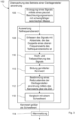
- Fig. 2 to 4 show process steps of three embodiments 100, 102, 104 of the method.
- Fig. 2 shows a first embodiment 100 of the method.
- vibrations arise in the plain bearing arrangement 12. These vibrations spread in the form of structure-borne sound in the plain bearing arrangement 12 and also in components adjacent to the plain bearing arrangement 12.
- the vibratable seismic mass 24 of the acceleration sensor 22 is excited to vibrate by the structure-borne sound.
- a signal 38 is generated by exciting the vibratable seismic mass 24 of the acceleration sensor 22 and a piezoelectric effect ( Fig. 1 ), which characterizes the vibration excitation associated with the plain bearing arrangement 12.
- the memory 20 and the computer program code stored therein are configured in cooperation with the processor 18 to process the signal 38 of the acceleration sensor 22 only in a partial frequency range 40 containing the resonance frequency 26 (see also Fig. 5 ) to be evaluated.
- the sub-frequency range 40 is limited by an upper frequency value 42 and a lower frequency value 44.
- the signal 38 of the acceleration sensor 22 is recorded over time and at a sampling rate that preferably corresponds to at least twice the upper frequency value 42. Because the sampling rate corresponds to twice the upper frequency value 42 of the partial frequency range 40 to be evaluated, the signal 38 is limited to the upper frequency value 42 for the evaluation.
- an averaged characteristic value is formed from the recorded partial frequency range 40 in method step 110.
- Various mathematical methods which were mentioned at the beginning, are available for forming an averaged characteristic value, for example the root mean square of the signal 38 of the sensor 14.
- a friction state of the plain bearing arrangement 12 can be concluded in method step 112. Starting from a hydrodynamic friction state, a friction state characterized by mixed friction is concluded if the characteristic value increases over time.
- a warning message 114 is preferably issued, which can be displayed, for example, by means of the display device 28, so that, for example, maintenance can be carried out on the plain bearing arrangement 12.
- a warning message 114 is preferably issued, which can be displayed, for example, by means of the display device 28, so that, for example, maintenance can be carried out on the plain bearing arrangement 12.
- plain bearing arrangements 12 of offshore wind turbines it is thus possible for plain bearing arrangements 12 of offshore wind turbines to be maintained according to their operating state.
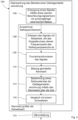
- Fig. 3 schematically depicts a second embodiment 102 of the method.
- the signal 38 is Fig.2 in a method step 108 with a sampling rate and then filtered in a method step 116 by means of a high-pass filter and by means of a low-pass filter.
- a cutoff frequency of the high-pass filter can correspond to the lower frequency value 44 of the partial frequency range 40 and a cutoff frequency of the low-pass filter can correspond to the upper frequency value 42 of the partial frequency range 40.
- the signal 38 is thus limited to the partial frequency range 40 to be evaluated.
- Fig. 3 a further variant is implemented in which, after the averaged characteristic value has been formed in method step 110, an optional method step 118 is carried out in addition to method step 112 or as part of it.
- the characteristic value is compared with a threshold value for mixed friction, so that, starting from a hydrodynamic friction state, a friction state characterized by mixed friction is concluded if the characteristic value increases over time and exceeds the predetermined threshold value. If mixed friction is detected or mixed friction is concluded, a warning message 114 can preferably be issued.
- the previously defined and stored threshold value can be based on calculations, tests or empirical values.
- Fig. 4 schematically depicts a third embodiment 104 of the method.
- the third embodiment 104 for example, no high/low pass filtering according to the second embodiment 102 is carried out, but rather according to the Acquiring the signal 38 with a sampling rate in method step 108, in a subsequent method step 120 the acquired signal 38 is Fourier transformed (see also Fig. 5 ) and then only evaluated in the partial frequency range 40.
- method step 112 of determining the friction state is carried out, in particular again optionally based on a threshold value comparison according to method step 118. Again, a warning message can be issued if the characteristic value increases over time and exceeds the predetermined threshold value.
- the friction state is therefore monitored over time in all process variants.
- a warning message 114 can be issued if mixed friction is detected.
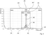
- Fig. 5 is an exemplary graphical representation of two Fourier-transformed signals 46, 48 of a single-axis acceleration sensor 22 with a resonance frequency 26 of 47 kHz under different friction conditions.
- a first Fourier-transformed signal 46 with a lower amplitude (shown as a black line) represents a hydrodynamic friction condition
- a second Fourier-transformed signal 48 with a larger amplitude (shown as a gray line) represents a friction condition with mixed friction.
- the second Fourier-transformed signal 48 has a significantly greater amplitude in the range of the resonance frequency 26 in the case of mixed friction than that of the first Fourier-transformed signal 46 in the case of hydrodynamic friction.
- the acceleration sensor 22 is The area of resonance frequency 26, i.e. at the highest sensitivity, is most strongly excited, and the mixed friction state can thus be detected starting from a hydrodynamic friction state.
- Fig. 5 two alternative sub-frequency ranges 40', 40'' containing the resonance frequency 26 are shown.
- the upper frequency value 42 is 1.7 times the resonance frequency 26 and the lower frequency value 44 is 0.3 times the resonance frequency 26.
- the upper frequency value 42 is 1.2 times the resonance frequency 26 and the lower frequency value 44 is 0.8 times the resonance frequency 26.
- Different partial frequency ranges 40 are to be selected depending on the design of the acceleration sensor 22. The smaller the partial frequency range 40 to be evaluated, the smaller the amount of data to be evaluated.
- the resonance frequency 26 of the acceleration sensor 22 coupled to the plain bearing location/arrangement 12 and the nature of the friction conditions in the range of the resonance frequency 26 are not known, then the partial frequency range 40 to be advantageously evaluated and the resonance frequency 26 of the acceleration sensor 22 in the installation situation can be in one experiment and by means of Fourier transformation.
Landscapes
- Physics & Mathematics (AREA)
- General Physics & Mathematics (AREA)
- Engineering & Computer Science (AREA)
- General Engineering & Computer Science (AREA)
- Mechanical Engineering (AREA)
- Chemical & Material Sciences (AREA)
- Analytical Chemistry (AREA)
- Acoustics & Sound (AREA)
- Testing Of Devices, Machine Parts, Or Other Structures Thereof (AREA)
- Measurement Of Mechanical Vibrations Or Ultrasonic Waves (AREA)
Description
Die Erfindung betrifft ein Verfahren und eine Vorrichtung zur Überwachung eines Betriebs einer Gleitlagerstelle/-anordnung mittels eines Sensors, wobei durch den Sensor ein Signal erzeugt wird, welches Signal eine mit der Gleitlagerstelle/- anordnung assoziierte Schwingungsanregung charakterisiert. Ferner betrifft die Erfindung eine Gleitlagerstelle/- anordnung, welche mechanisch gekoppelt ist mit der erfindungsgemäßen Vorrichtung.The invention relates to a method and a device for monitoring the operation of a plain bearing point/arrangement by means of a sensor, wherein the sensor generates a signal which characterizes a vibration excitation associated with the plain bearing point/arrangement. The invention further relates to a plain bearing point/arrangement which is mechanically coupled to the device according to the invention.
Gleitlager werden in unterschiedlichen Bereichen der Industrie eingesetzt. Dabei kommen Gleitlager auch in großen Maschinen, wie beispielsweise Windkraftanlagen, zum Einsatz. Eine Überwachung von Gleitlagern dient dem Erfassen von fehlerhaften Betriebszuständen, welche zur Schädigung oder zum Stillstand der gesamten Maschine führen können. Ferner können durch die Überwachung von Gleitlagern Wartungsintervalle optimiert werden.Plain bearings are used in various areas of industry. Plain bearings are also used in large machines, such as wind turbines. Monitoring plain bearings is used to detect faulty operating conditions that can lead to damage or downtime of the entire machine. Furthermore, monitoring plain bearings can be used to optimize maintenance intervals.
Wenn im Rahmen dieser Anmeldung von einer Gleitlagerstelle oder Gleitlageranordnung die Rede ist, dann wird hierunter verstanden, dass eine Komponente, beispielsweise eine Welle oder ein Zapfen, bezüglich einer anderen Komponente, beispielsweise eine Gehäusekomponente, möglichst reibungsarm drehbar oder verschieblich gleitgelagert ist oder auch nur gleitbeweglich abgestützt ist. Zwischen den Komponenten oder an wenigstens einer der Komponenten ist üblicherweise eine Gleitschicht, eine Gleitbeschichtung oder ein Schmierfilm ausgebildet. Zwischen den Komponenten oder zur Lagerung einer der Komponenten kann ein buchsenförmiges Gleitlagerelement mit Gleitschicht vorgesehen sein. Beispielsweise kann eine Gleitlagerstelle/-anordnung ein Gehäuse, ein darin typischerweise festsitzend eingesetztes Gleitlagerelement und ein darin gelagertes Wellenteil umfassen. Eine Gleitlagerstelle/-anordnung kann aber auch ein Maschinenteil, insbesondere ein Zahnrad, als erste Komponente umfassen, welches auf einer Welle als zweiter Komponente drehbar gleitgelagert ist. Die Welle kann hierfür ein buchsenförmiges Gleitelement oder eine Gleitbeschichtung umfassen.When this application refers to a plain bearing point or plain bearing arrangement, this is understood to mean that a component, for example a shaft or a pin, is mounted in a sliding manner with as little friction as possible relative to another component, for example a housing component, or is only supported in a sliding manner. A sliding layer, a sliding coating or a lubricating film is usually formed between the components or on at least one of the components. A bush-shaped plain bearing element with a sliding layer can be provided between the components or for mounting one of the components. For example, a plain bearing point/arrangement can comprise a housing, a plain bearing element typically firmly inserted therein and a shaft part mounted therein. A plain bearing point/arrangement can also comprise a machine part, in particular a gear, as the first component, which is rotatably mounted on a shaft as the second component. The shaft can comprise a bush-shaped sliding element or a sliding coating for this purpose.
Aus der
Ferner ist aus der
Der vorliegenden Erfindung liegt die Aufgabe zugrunde, ein vereinfachtes Verfahren zur Überwachung des Betriebs einer Gleitlagerstelle/ -anordnung mit einer verringerten Datenmengenerfassung und dennoch sicherer Datenauswertung bereit zu stellen.The present invention is based on the object of providing a simplified method for monitoring the operation of a plain bearing location/arrangement with a reduced amount of data acquisition and yet reliable data evaluation.
Die Aufgabe wird erfindungsgemäß gelöst durch ein Verfahren zur Überwachung des Betriebs einer Gleitlagerstelle/-anordnung mit den Merkmalen des Anspruchs 1. Vorteilhafte Ausführungsformen finden sich in den Unteransprüchen.The object is achieved according to the invention by a method for monitoring the operation of a plain bearing location/arrangement having the features of claim 1. Advantageous embodiments can be found in the subclaims.
Es wird also erfindungsgemäß vorgeschlagen, dass der Sensor ein piezoelektrischer Beschleunigungssensor ist und dass der piezoelektrische Beschleunigungssensor eine schwingfähige seismische Masse aufweist und demgemäß eine Resonanzfrequenz aufweist und dass die Resonanzfrequenz in einer Einbausituation des Sensors in einem Bereich von 20 bis 70 kHz liegt,
- und dass das Signal des Beschleunigungssensors nur in einem die Resonanzfrequenz beinhaltenden Teilfrequenzbereich ausgewertet wird, der durch einen oberen Frequenzwert und einen unteren Frequenzwert begrenzt wird,
- und dass das Signal des Beschleunigungssensors über die Zeit und mit einer Abtastrate erfasst wird, die wenigstens dem zweifachen des oberen Frequenzwerts entspricht,
- und dass aus dem Signal des Beschleunigungssensors in diesem Teilfrequenzbereich ein gemittelter Kennwert gebildet wird, und dass anhand des Kennwerts auf einen Reibzustand der Gleitlagerstelle/-anordnung geschlossen wird, und dass ausgehend von einem hydrodynamischen Reibzustand auf einen durch Mischreibung geprägten Reibzustand geschlossen wird, wenn der Kennwert im zeitlichen Verlauf ansteigt.
- and that the signal of the acceleration sensor is only evaluated in a partial frequency range containing the resonance frequency, which is limited by an upper frequency value and a lower frequency value,
- and that the signal of the acceleration sensor is recorded over time and at a sampling rate that is at least twice the upper frequency value,
- and that an averaged characteristic value is formed from the signal of the acceleration sensor in this partial frequency range, and that a friction state of the plain bearing location/arrangement is inferred on the basis of the characteristic value, and that, starting from a hydrodynamic friction state, a friction state characterized by mixed friction is inferred if the characteristic value increases over time.
Im Betrieb entstehen in der Gleitlagerstelle/-anordnung Schwingungen, die sich in Form von Körperschall in der Gleitlagerstelle/-anordnung und auch in angrenzende Komponenten ausbreitet.During operation, vibrations arise in the plain bearing location/arrangement, which spread in the form of structure-borne sound in the plain bearing location/arrangement and also in adjacent components.
Die schwingfähige seismische Masse des piezoelektrischen Beschleunigungssensors wird durch den im Betrieb der Gleitlagerstelle/-anordnung entstehenden Körperschall zum Schwingen angeregt. Über den piezoelektrischen Effekt wird aus der Schwingung der seismischen Masse das Signal des Sensors erzeugt, welches die mit der Gleitlagerstelle/-anordnung assoziierte Schwingungsanregung charakterisiert. Dabei ist insbesondere die Amplitude des Körperschalls abhängig von dem Reibungszustand der Gleitlagerstelle/-anordnung, alsohydrodynamische Reibung, Mischreibung oder insbesondere Festkörperreibung. Der Beschleunigungssensor kann ein ein-, zwei- oder dreiachsiger piezoelektrischer Beschleunigungssensor mit seismischer Masse sein.The vibrating seismic mass of the piezoelectric acceleration sensor is excited to vibrate by the structure-borne noise generated during operation of the plain bearing point/arrangement. The piezoelectric effect is used to generate the sensor signal from the vibration of the seismic mass, which characterizes the vibration excitation associated with the plain bearing point/arrangement. The amplitude of the structure-borne noise is particularly dependent on the friction state of the plain bearing point/arrangement, i.e. hydrodynamic friction, mixed friction or, in particular, Solid friction. The acceleration sensor can be a single-, two- or three-axis seismic mass piezoelectric acceleration sensor.
Der Beschleunigungssensor ist mittels der schwingfähigen seismischen Masse derart ausgebildet, dass seine Resonanzfrequenz in der Einbausituation in einem Bereich von 20 bis 70kHz liegt. Die Resonanzfrequenz des Beschleunigungssensors ist sensorspezifisch, aber auch abhängig von der Einbausituation bzw. der Befestigung des Beschleunigungssensors an der Gleitlagerstelle/-anordnung, beispielsweise mittels Verschrauben, Verkleben, magnetischer Anordnung etc.. Ist die Resonanzfrequenz des Beschleunigungssensors in seiner Einbausituation nicht bekannt, dann sollte sie vorneweg bestimmt werden.The acceleration sensor is designed using the vibrating seismic mass in such a way that its resonance frequency in the installation situation is in a range of 20 to 70 kHz. The resonance frequency of the acceleration sensor is sensor-specific, but also depends on the installation situation or the fastening of the acceleration sensor to the plain bearing location/arrangement, for example by screwing, gluing, magnetic arrangement, etc. If the resonance frequency of the acceleration sensor in its installation situation is not known, then it should be determined in advance.
In einem weiteren Verfahrensschritt wird das Signal des Beschleunigungssensors in dem die Resonanzfrequenz beinhaltenden Teilfrequenzbereich ausgewertet.In a further process step, the signal of the acceleration sensor is evaluated in the partial frequency range containing the resonance frequency.
Tritt Mischreibung in der Gleitlagerstelle/-anordnung auf, dann wird der Beschleunigungssensor im Resonanzbereich verstärkt angeregt, wodurch das Signal des Beschleunigungssensors in dem Teilfrequenzbereich verstärkt wird. D.h. der Beschleunigungssensor wird im Bereich mit der höchsten Empfindlichkeit ausgewertet, was zu einer hohen Zuverlässigkeit des Verfahrens führt. Somit ist es mit dem erfindungsgemäßen Verfahren auch möglich, bei niedrigen Drehzahlen (niedrigen Gleitgeschwindigkeiten z.B. Start Stopp Betrieb) den durch Mischreibung in Gleitlagern erzeugten Körperschall zu erfassen.If mixed friction occurs in the plain bearing location/arrangement, the acceleration sensor is stimulated more strongly in the resonance range, whereby the signal from the acceleration sensor is amplified in the partial frequency range. This means that the acceleration sensor is evaluated in the range with the highest sensitivity, which leads to a high level of reliability of the method. Thus, the method according to the invention also makes it possible to record the structure-borne noise generated by mixed friction in plain bearings at low speeds (low sliding speeds, e.g. start-stop operation).
Dadurch, dass die Abtastrate wenigstens dem zweifachen des oberen Frequenzwerts des auszuwertenden Teilfrequenzbereichs entspricht, kann eine Auswertung des Signals des Beschleunigungssensors bis zu dem oberen Frequenzwert durchgeführt werden. Ist beispielsweise die Abtastrate genau auf das Zweifache des auszuwertenden Teilfrequenzbereichs beschränkt, dann wird das auswertbare Signal auf den oberen Frequenzwert begrenzt.Because the sampling rate is at least twice the upper frequency value of the partial frequency range to be evaluated, the acceleration sensor signal can be evaluated up to the upper frequency value. If, for example, the sampling rate is limited to exactly twice the partial frequency range to be evaluated, the signal that can be evaluated is limited to the upper frequency value.
Der zu überwachende Teilfrequenzbereich ist vorzugsweise unabhängig von einem Lagermaterial, einer Drehzahl (Gleitgeschwindigkeit), einer Belastung und einem Schmierstoff sowie einer Schmierstofftemperatur.The partial frequency range to be monitored is preferably independent of a bearing material, a rotational speed (sliding speed), a load and a lubricant as well as a lubricant temperature.
Bei der Auswertung wird aus dem Signal des Beschleunigungssensors in diesem Teilfrequenzbereich ein Kennwert gebildet. Steigt der Kennwert im zeitlichen Verlauf an, so kann auf eine Mischreibung geschlossen werden. Ein Vergleich mit einer hinterlegten Referenzwerttabelle ist nicht zwingend erforderlich, was als vorteilhaft erachtet wird. Es ist in einfacher Weise eine Echt-Zeit Überwachung im Betrieb der Gleitlagerstelle/-anordnung realisierbar. Eine Mischreibung der Gleitlagerstelle/-anordnung ist zuverlässig erkennbar, und einer Schädigung der Gleitlagerstelle/- anordnung kann vorgebeugt werden, bspw. in dem eine Wartung der Gleitlagerstelle/-anordnung frühzeitig durchgeführt wird.During the evaluation, a characteristic value is formed from the signal of the acceleration sensor in this partial frequency range. If the characteristic value increases over time, mixed friction can be concluded. A comparison with a stored reference value table is not absolutely necessary, which is considered advantageous. Real-time monitoring of the plain bearing point/arrangement during operation can be implemented in a simple manner. Mixed friction of the plain bearing point/arrangement can be reliably identified, and damage to the plain bearing point/arrangement can be prevented, for example by carrying out maintenance on the plain bearing point/arrangement at an early stage.
Es erweist sich als vorteilhaft, wenn die Resonanzfrequenz in der Einbausituation des Sensors in einem Bereich von 20 bis 50 kHz, insbesondere von 20 bis 40 kHz liegt. Dadurch, dass der Bereich in dem die Resonanzfrequenz liegt kleiner ist, kann auch der auszuwertende Teilfrequenzbereich verkleinert werden, wodurch eine geringere Datenmenge anfällt und auszuwerten ist.It is advantageous if the resonance frequency in the installation situation of the sensor is in a range of 20 to 50 kHz, especially 20 to 40 kHz. Because the range in which the resonance frequency lies is smaller, the partial frequency range to be evaluated can also be reduced. which means that a smaller amount of data is generated and needs to be evaluated.
In einer vorteilhaften Ausführungsform beträgt der obere Frequenzwert höchstens das 1,2-Fache oder höchstens das 1,3-Fache oder höchstens das 1,4-Fache oder höchstens das 1,5-Fache oder höchstens das 1,6-Fache oder höchstens das 1,7-Fache der Resonanzfrequenz.In an advantageous embodiment, the upper frequency value is at most 1.2 times or at most 1.3 times or at most 1.4 times or at most 1.5 times or at most 1.6 times or at most 1.7 times the resonance frequency.
Nach einer Ausführungsform der Erfindung hat es sich als vorteilhaft erwiesen, wenn der untere Frequenzwert mindestens das 0,8-Fache oder mindestens das 0,7-Fache oder mindestens das 0,6-Fache oder mindestens das 0,5-Fache oder mindestens das 0,4- oder mindestens das 0,3-Fache der Resonanzfrequenz beträgt.According to one embodiment of the invention, it has proven advantageous if the lower frequency value is at least 0.8 times or at least 0.7 times or at least 0.6 times or at least 0.5 times or at least 0.4 times or at least 0.3 times the resonance frequency.
Es ist vorteilhaft, wenn der Kennwert ein statistischer Mittelwert ist, insbesondere der quadratische Mittelwert (RMS), der Maximalwert, der Spitze-Tal-Wert, die Varianz (Verteilung der Werte um den Mittelwert), der Kurtosiswert (Maß für die Steilheit), ein Scheitelwert (Verhältnis des Maximalwerts zum quadratischen Mittelwert). Der Kennwert ist einfacher zu handhaben als das erfasste Signal des Beschleunigungssensors. Durch die Bildung des Kennwerts werden störende Signalteile und/oder Ausreiser im Signal des Beschleunigungssensors kompensiert. Trends und Entwicklungen des Kennwerts lassen sich über die Zeit erfassen.It is advantageous if the characteristic value is a statistical mean, in particular the root mean square (RMS), the maximum value, the peak-valley value, the variance (distribution of the values around the mean), the kurtosis value (measure of the steepness), a peak value (ratio of the maximum value to the root mean square). The characteristic value is easier to handle than the signal recorded by the acceleration sensor. By forming the characteristic value, disturbing signal parts and/or outliers in the signal of the acceleration sensor are compensated. Trends and developments of the characteristic value can be recorded over time.
Bei einer Ausführungsform hat es sich als vorteilhaft erwiesen, wenn ausgehend von einem hydrodynamischen Reibzustand auf einen durch Mischreibung geprägten Reibzustand geschlossen wird, wenn der Kennwert im zeitlichen Verlauf einen vorgegebenen oder vorgebbaren Schwellwert übersteigt. Es ist auch denkbar, dass zusätzlich ein Schwellwert für Festkörperreibung vorgegeben werden kann für den Fall, dass die Mischreibung überschritten wird. Durch einen Schwellwert kann sichergestellt werden, dass Mischreibung zuverlässig erkannt wird. Ferner wird als vorteilhaft angesehen, dass schon bei Inbetriebnahme der Gleitlagerstelle/-anordnung mit Hilfe des Schwellwerts Mischreibung erkannt werden kann, falls der gebildete Kennwert den Schwellwert überschreitet.In one embodiment, it has proven to be advantageous if, starting from a hydrodynamic friction state, a friction state characterized by mixed friction is concluded if the characteristic value over time exceeds a specified or predeterminable threshold value. It is also conceivable that a threshold value for solid body friction can also be specified in the event that mixed friction is exceeded. A threshold value can ensure that mixed friction is reliably detected. It is also considered advantageous that mixed friction can be detected when the plain bearing point/arrangement is put into operation using the threshold value if the characteristic value formed exceeds the threshold value.
Es ist weiter vorteilhaft, wenn das Signal des Beschleunigungssensors mittels eines Hochpassfilters und insbesondere zusätzlich mittels eines Tiefpassfilters gefiltert wird. Das Signal kann mittels des Hochpassfilters und insbesondere zusätzlich mittels des Tiefpassfilters vor der Bildung des Kennwerts von für die Überwachung unnötigen Teilfrequenzbereichen bereinigt werden.It is further advantageous if the signal from the acceleration sensor is filtered using a high-pass filter and in particular additionally using a low-pass filter. The signal can be cleaned of sub-frequency ranges that are unnecessary for monitoring using the high-pass filter and in particular additionally using the low-pass filter before the characteristic value is formed.
Bei einer Ausführungsform hat es sich als vorteilhaft erwiesen, wenn eine Grenzfrequenz des Hochpassfilters dem unteren Frequenzwert des Teilfrequenzbereichs entspricht und/oder dass eine Grenzfrequenz des Tiefpassfilters dem oberen Frequenzwert des Teilfrequenzbereichs entspricht. Das Signal kann auf den auszuwertenden Teilfrequenzbereich begrenzt werden, sodass eine geringere Datenmenge erzeugt wird, als wenn das ungefilterte Signal ausgewertet wird. Es entstehen geringere Kosten und eine Zeitersparnis für die Messdatenerfassung und Messdatenauswertung.In one embodiment, it has proven advantageous if a cutoff frequency of the high-pass filter corresponds to the lower frequency value of the partial frequency range and/or that a cutoff frequency of the low-pass filter corresponds to the upper frequency value of the partial frequency range. The signal can be limited to the partial frequency range to be evaluated, so that a smaller amount of data is generated than if the unfiltered signal is evaluated. This results in lower costs and time savings for the measurement data acquisition and evaluation.
Nach einer anderen Ausführungsform der Erfindung hat es sich als vorteilhaft erwiesen, wenn ein Signal des Beschleunigungssensors fouriertransformiert wird und daran anschließend nur in dem Teilfrequenzbereich ausgewertet wird. Diese Fouriertransformation stellt insbesondere eine Alternative zu einer Filterung dar.According to another embodiment of the invention, it has proven advantageous if a signal from the acceleration sensor is Fourier transformed and is then evaluated only in the partial frequency range. This Fourier transformation represents an alternative to filtering.
Gegenstand der Erfindung ist auch eine Vorrichtung zur Überwachung des Betriebs einer Gleitlagerstelle/-anordnung, umfassend einen Sensor, der mechanisch mit der Gleitlagerstelle/-anordnung gekoppelt anordenbar oder angeordnet ist, wobei durch den Sensor ein Signal erzeugt wird, welches Signal eine mit der Gleitlagerstelle/-anordnung assoziierte Schwingungsanregung charakterisiert,
- und weiter umfassend eine elektronische Auswerteeinrichtung mit einem Prozessor und einem Speicher mit einem darauf abgelegten Computerprogrammcode, wobei der Sensor ein piezoelektrischer Beschleunigungssensor ist und dass der piezoelektrische Beschleunigungssensor eine schwingfähige seismische Masse aufweist und demgemäß eine Resonanzfrequenz aufweist, wobei die seismische Masse durch Körperschall der Gleitlagerstelle/-anordnung zum Schwingen angeregt wird und hierdurch das Signal erzeugt wird, wobei die Resonanzfrequenz in einer Einbausituation des Sensors in
einem Bereich von 20 bis 70 kHz liegt, - und dass der Speicher und der Computerprogrammcode im Zusammenwirken mit dem Prozessor konfiguriert sind, um das Signal des Beschleunigungssensors nur in einem die Resonanzfrequenz beinhaltenden Teilfrequenzbereich auszuwerten, der durch einen oberen Frequenzwert und einen unteren Frequenzwert begrenzt wird,
- und weiter konfiguriert sind, um das Signal des Beschleunigungssensors über die Zeit und mit einer Abtastrate zu erfassen, die wenigstens dem zweifachen des oberen Frequenzwerts entspricht,
- und weiter konfiguriert sind, um aus dem Signal des Beschleunigungssensors in diesem Teilfrequenzbereich einen gemittelten Kennwert zu bilden,
- und anhand des Kennwerts auf einen Reibzustand der Gleitlagerstelle/-anordnung zu schließen,
- und weiter konfiguriert sind, um ausgehend von einem hydrodynamischen Reibzustand auf einen durch Mischreibung geprägten Reibzustand zu schließen, wenn der Kennwert im zeitlichen Verlauf ansteigt. - Die Vorrichtung ist also zur Ausführung des erfindungsgemäßen Verfahrens ausgebildet.
- and further comprising an electronic evaluation device with a processor and a memory with a computer program code stored thereon, wherein the sensor is a piezoelectric acceleration sensor and that the piezoelectric acceleration sensor has an oscillatable seismic mass and accordingly has a resonance frequency, wherein the seismic mass is excited to oscillate by structure-borne sound of the plain bearing point/arrangement and the signal is thereby generated, wherein the resonance frequency in an installation situation of the sensor is in a range of 20 to 70 kHz,
- and that the memory and the computer program code are configured in cooperation with the processor to evaluate the signal of the acceleration sensor only in a partial frequency range containing the resonance frequency, which is limited by an upper frequency value and a lower frequency value,
- and further configured to acquire the acceleration sensor signal over time and at a sampling rate that is at least twice the upper frequency value,
- and are further configured to form an averaged characteristic value from the signal of the acceleration sensor in this partial frequency range,
- and to use the characteristic value to determine the frictional condition of the plain bearing location/arrangement,
- and are further configured to conclude from a hydrodynamic friction state that there is a friction state characterized by mixed friction if the characteristic value increases over time. - The device is thus designed to carry out the method according to the invention.
Bei einer weiteren Ausführungsform hat es sich als vorteilhaft erwiesen, wenn die Vorrichtung einen Hochpassfilter und insbesondere zusätzlich einen Tiefpassfilter umfasst, und dass das Signal des Beschleunigungssensors mittels des Hochpassfilters und insbesondere zusätzlich mittels des Tiefpassfilters gefiltert wird. Ein Hochpassfilter und insbesondere der Tiefpassfilter können beispielsweise als elektrotechnische Bauelemente ausgebildet sein. Es ist auch denkbar, dass der Speicher und der Computerprogrammcode im Zusammenwirken mit dem Prozessor als Hochpass- und insbesondere als Tiefpassfilter konfiguriert sein können.In a further embodiment, it has proven advantageous if the device comprises a high-pass filter and in particular additionally a low-pass filter, and that the signal of the acceleration sensor is filtered by means of the high-pass filter and in particular additionally by means of the low-pass filter. A high-pass filter and in particular the low-pass filter can be designed, for example, as electrical components. It is also conceivable that the memory and the computer program code can be configured as a high-pass filter and in particular as a low-pass filter in conjunction with the processor.
Es hat sich als vorteilhaft erwiesen, wenn eine Grenzfrequenz des Hochpassfilters dem unteren Frequenzwert des Teilfrequenzbereichs entspricht und/oder dass eine Grenzfrequenz des Tiefpassfilters dem oberen Frequenzwert des Teilfrequenzbereichs entspricht.It has proven advantageous if a cutoff frequency of the high-pass filter corresponds to the lower frequency value of the sub-frequency range and/or that a cutoff frequency of the low-pass filter corresponds to the upper frequency value of the sub-frequency range.
Nach einer weiteren Ausführungsform hat es sich als vorteilhaft erwiesen, dass die elektronische Auswerteeinrichtung ausgebildet ist, das Signal des Beschleunigungssensors fourier zu transformieren und daran anschließend nur in dem Teilfrequenzbereich auszuwerten.According to a further embodiment, it has proven advantageous that the electronic evaluation device is designed to evaluate the signal of the acceleration sensor and then evaluate it only in the partial frequency range.
Ein weiterer Gegenstand der Erfindung ist eine Gleitlagerstelle/-anordnung, welche mechanisch gekoppelt ist mit einer erfindungsgemäßen Vorrichtung zur Überwachung des Betriebs der Gleitlagerstelle/-anordnung, so dass von der Gleitlagerstelle/-anordnung erzeugter Körperschall auf die Vorrichtung und deren piezoelektrischen Beschleunigungssensor übertragen und durch die Vorrichtung überwacht werden kann.A further subject matter of the invention is a plain bearing point/arrangement which is mechanically coupled to a device according to the invention for monitoring the operation of the plain bearing point/arrangement, so that structure-borne sound generated by the plain bearing point/arrangement can be transmitted to the device and its piezoelectric acceleration sensor and monitored by the device.
Weitere Merkmale und Vorteile der Erfindung sind Gegenstand der nachfolgenden Beschreibung und der zeichnerischen Darstellung von Ausführungsbeispielen. Es zeigen:
- Fig. 1
- eine schematische und teilgeschnittene Ansicht einer Gleitlagerstelle/-anordnung und einer Vorrichtung zur Überwachung des Betriebs der Gleitlagerstelle/anordnung;
- Fig. 2
- eine schematische Darstellung von Schritten eines erfindungsgemäßen Verfahrens zum Überwachen einer Gleitlagerstelle/-anordnung nach einer ersten Ausführungsform;
- Fig. 3
- eine schematische Darstellung von Schritten des erfindungsgemäßen Verfahrens nach einer zweiten Ausführungsform;
- Fig. 4
- eine schematische Darstellung von Schritten des erfindungsgemäßen Verfahrens nach einer dritten Ausführungsform;
- Fig. 5
- eine grafische Darstellung zweier fouriertransformierter Signale unterschiedlicher Reibzustände eines Beschleunigungssensors.
- Fig. 1
- a schematic and partially sectioned view of a plain bearing location/arrangement and a device for monitoring the operation of the plain bearing location/arrangement;
- Fig. 2
- a schematic representation of steps of a method according to the invention for monitoring a plain bearing location/arrangement according to a first embodiment;
- Fig. 3
- a schematic representation of steps of the method according to the invention according to a second embodiment;
- Fig. 4
- a schematic representation of steps of the method according to the invention according to a third embodiment;
- Fig. 5
- a graphical representation of two Fourier-transformed signals of different friction states of an acceleration sensor.
Die nur schematisch angedeutete Gleitlageranordnung 12 umfasst hier beispielhaft ein Gleitlagergehäuse 30 und eine in dem Gleitlagergehäuse 30 gelagerte Welle 32, wobei weitere zwischen den Komponenten gegebenenfalls wirkende Gleitelemente oder Gleitbeschichtungen nicht dargestellt sind. Zwischen dem Gleitlagergehäuse 30 und der Welle 32 ist typischerweise ein Schmierfilm 34 für eine hydrodynamische Lagerung der Welle 32 vorgesehen, der über an sich bekannte Mittel ausgebildet wird, was daher nicht beschrieben wird. An einer Außenseite 36 des Gleitlagergehäuses 30 ist der Beschleunigungssensor 22 angeordnet und kann beispielsweise an dem Gleitlagergehäuse 30 verschraubt sein.The
Die Vorrichtung 10 ist ausgebildet, um ein erfindungsgemäßes Verfahren der eingangs beschriebenen Ausbildung durchzuführen.
Der Speicher 20 und der darin abgelegte Computerprogrammcode sind im Zusammenwirken mit dem Prozessor 18 konfiguriert, das Signal 38 des Beschleunigungssensors 22 nur in einem die Resonanzfrequenz 26 beinhaltenden Teilfrequenzbereich 40 (siehe auch
Nachfolgend wird aus dem erfassten Teilfrequenzbereich 40 im Verfahrensschritt 110 ein gemittelter Kennwert gebildet. Zur Bildung eines gemittelten Kennwerts stehen verschiedene mathematische Methoden, die eingangs genannt wurden, zur Verfügung, bspw. der quadratische Mittelwert des Signals 38 des Sensors 14.Subsequently, an averaged characteristic value is formed from the recorded
Anhand des gebildeten Kennwerts kann im Verfahrensschritt 112 auf einen Reibzustand der Gleitlageranordnung 12 geschlossen werden. Es wird ausgehend von einem hydrodynamischen Reibzustand auf einen durch Mischreibung geprägten Reibzustand geschlossen, wenn der Kennwert im zeitlichen Verlauf ansteigt.Based on the characteristic value formed, a friction state of the
Wird Mischreibung festgestellt, wird vorzugsweise eine Warnmeldung 114 ausgegeben, die beispielsweise mittels der Anzeigeeinrichtung 28 wiedergegeben werden kann, sodass beispielsweise eine Wartung der Gleitlageranordnung 12 durchgeführt werden kann. Beispielsweise ist es somit möglich, dass Gleitlageranordnungen 12 von Offshore Windrädern entsprechend ihrem Betriebszustand gewartet werden.If mixed friction is detected, a
Ferner ist bei
Es wird also bei allen Verfahrensvarianten der Reibzustand über die Zeit überwacht. Vorzugsweise kann eine Warnmeldung 114 ausgegeben werden, wenn Mischreibung festgestellt wird.The friction state is therefore monitored over time in all process variants. Preferably, a
Das zweite fouriertransformierte Signal 48 weist bei Mischreibung im Bereich der Resonanzfrequenz 26 eine deutlich größere Amplitude auf, als diejenige des ersten fouriertransformierten Signals 46 bei hydrodynamischer Reibung. Bei Mischreibung wird der Beschleunigungssensor 22 im Bereich der Resonanzfrequenz 26, d.h. bei der höchsten Empfindlichkeit, am stärksten angeregt, und der Mischreibungszustand ist ausgehend von einem hydrodynamischen Reibzustand somit erfassbar.The second Fourier-transformed
In
Claims (14)
- Method (100, 102, 104) for monitoring the operation of a plain bearing location/arrangement (12) by means of a sensor (14), wherein the sensor (14) generates a signal (38), which signal (38) characterizes (106) an oscillation excitation associated with the plain bearing location/arrangement (12), characterized in that the sensor (14) is a piezoelectric acceleration sensor (22), and that the piezoelectric acceleration sensor (22) has an oscillatable seismic mass (24) and accordingly a resonance frequency (26), and that, when the sensor (14) is in an installed situation, the resonance frequency (26) lies within a range of 20 to 70 kHz, and that the signal (38) of the acceleration sensor (22) is evaluated only in a partial frequency range (40, 40', 40") which contains the resonance frequency (26) and is limited by an upper frequency value (42) and a lower frequency value (44), and that the signal (38) of the acceleration sensor (22) is recorded over time and at a sampling rate, which corresponds (108) to at least twice the upper frequency value (42),and that an averaged characteristic value is formed (110) from the signal (38) of the acceleration sensor (22) in this partial frequency range (40, 40', 40"),and that a friction state of the plain bearing location/arrangement is inferred (112) on the basis of the characteristic value, and that, starting from a hydrodynamic friction state, a friction state characterized by mixed friction is inferred if the characteristic value increases over the course of time.
- Method (100, 102, 104) according to claim 1, characterized in that, when the sensor (14) is in the installed situation, the resonance frequency (26) lies within a range of 20 to 50 kHz, in particular of 20 to 40 kHz.
- Method (100, 102, 104) according to one of claims 1 or 2,
characterized in that the upper frequency value (42) is at most 1.2 times, or at most 1.3 times, or at most 1.4 times, or at most 1.5 times, or at most 1.6 times, or at most 1.7 times the resonance frequency (26). - Method (100, 102, 104) according to one of the preceding claims,
characterized in that the lower frequency value (44) is at least 0.8 times, or at least 0.7 times, or at least 0.6 times, or at least 0.5 times, or at least 0.4 or at least 0.3 times the resonance frequency (26). - Method (100, 102, 104) according to one of the preceding claims,
characterized in that the characteristic value is a statistical mean value, in particular the quadratic mean value, the maximum value, the peak-to-valley value, the variance, the kurtosis value, a peak value. - Method (102, 104) according to one of the preceding claims,
characterized in that, starting from a hydrodynamic friction state, a friction state characterized by mixed friction is inferred if the characteristic value exceeds (118) a predetermined or predeterminable threshold value over the course of time. - Method (102) according to one of the preceding claims,
characterized in that the signal (38) of the acceleration sensor (22) is filtered (116) by means of a high-pass filter and, in particular, additionally by means of a low-pass filter. - Method (102) according to claim 7, characterized in that a cutoff frequency of the high-pass filter corresponds to the lower frequency value (44) of the partial frequency range (40, 40', 40"), and/or that a cutoff frequency of the low-pass filter corresponds to the upper frequency value (42) of the partial frequency range (40, 40', 40").
- Method (104) according to one of claims 1 to 6, characterized in that a signal (38) of the acceleration sensor (22) is Fourier-transformed (120) and subsequently evaluated only in the partial frequency range (40, 40', 40").
- Device (10) for monitoring the operation of a plain bearing location/arrangement (12), comprising a sensor (14) which can be arranged or is arranged so as to be mechanically coupled to the plain bearing location/arrangement (12), wherein the sensor (14) generates a signal (38), which signal (38) characterizes (106) an oscillation excitation associated with the plain bearing location/arrangement (12),and further comprising an electronic evaluation apparatus (16) with a processor (18) and a memory (20) with a computer program code stored thereon, characterized in that the sensor (14) is a piezoelectric acceleration sensor (22), and that the piezoelectric acceleration sensor (22) has an oscillatable seismic mass (24) and accordingly a resonance frequency (26), wherein the seismic mass (24) is excited to oscillate by structure-borne sound of the plain bearing location/arrangement (12), and the signal (38) is thereby generated (106), wherein, when the sensor (14) is in an installed situation, the resonance frequency (26) is in a range of 20 to 70 kHz,and that the memory (20) and the computer program code are configured in cooperation with the processor (18) to evaluate the signal (38) of the acceleration sensor (22) only in a partial frequency range (40, 40', 40") which contains the resonance frequency (26) and is limited by an upper frequency value (42) and a lower frequency value (44),and are further configured to record the signal (38) of the acceleration sensor (22) over time and at a sampling rate that corresponds (108) to at least twice the upper frequency value (42), and are further configured to form (110) an averaged characteristic value from the signal (38) of the acceleration sensor (22) in this partial frequency range (40, 40', 40")and, on the basis of the characteristic value, to infer (112) a friction state of the plain bearing location/arrangement, and are further configured, starting from a hydrodynamic friction state, to infer a friction state characterized by mixed friction, when the characteristic value increases over the course of time.
- Device (10) according to claim 10, characterized in that the device (10) comprises a high-pass filter and, in particular, additionally a low-pass filter, and that the signal (38) of the acceleration sensor (22) is filtered (116) by means of the high-pass filter and, in particular, additionally by means of the low-pass filter.
- Device (10) according to claim 11, characterized in that a cutoff frequency of the high-pass filter corresponds to the lower frequency value (44) of the partial frequency range (40, 40', 40"), and/or that a cutoff frequency of the low-pass filter corresponds to the upper frequency value (42) of the partial frequency range (40, 40', 40").
- Device (10) according to claim 10, characterized in that the electronic evaluation apparatus (16) is designed to Fourier-transform (120) the signal (38) of the acceleration sensor (22) and then to evaluate it only in the partial frequency range (40, 40', 40").
- Plain bearing location/arrangement (12) which is mechanically coupled to a device (10) for monitoring the operation of the plain bearing location/arrangement (12) according to at least one of claims 10 to 13, so that structure-borne sound generated by the plain bearing location/arrangement (12) can be transmitted to the device (10) and its piezoelectric acceleration sensor (22) and monitored by the device (10).
Applications Claiming Priority (2)
| Application Number | Priority Date | Filing Date | Title |
|---|---|---|---|
| DE102022121294.7A DE102022121294A1 (en) | 2022-08-23 | 2022-08-23 | Method and device for monitoring the operation of a plain bearing point/arrangement and a corresponding plain bearing point/arrangement |
| PCT/EP2023/072718 WO2024041975A1 (en) | 2022-08-23 | 2023-08-17 | Method and device for monitoring the operation of a sliding bearing point/arrangement and a corresponding sliding bearing point/arrangement |
Publications (2)
| Publication Number | Publication Date |
|---|---|
| EP4359751A1 EP4359751A1 (en) | 2024-05-01 |
| EP4359751B1 true EP4359751B1 (en) | 2024-10-16 |
Family
ID=87797653
Family Applications (1)
| Application Number | Title | Priority Date | Filing Date |
|---|---|---|---|
| EP23758598.9A Active EP4359751B1 (en) | 2022-08-23 | 2023-08-17 | Method and device for monitoring the operation of a sliding bearing point/arrangement and a corresponding sliding bearing point/arrangement |
Country Status (4)
| Country | Link |
|---|---|
| EP (1) | EP4359751B1 (en) |
| DE (1) | DE102022121294A1 (en) |
| ES (1) | ES2996945T3 (en) |
| WO (1) | WO2024041975A1 (en) |
Families Citing this family (1)
| Publication number | Priority date | Publication date | Assignee | Title |
|---|---|---|---|---|
| DE102023126529B3 (en) * | 2023-09-28 | 2025-03-27 | Ks Gleitlager Gmbh | Method and device for determining a wear condition of a plain bearing arrangement |
Family Cites Families (7)
| Publication number | Priority date | Publication date | Assignee | Title |
|---|---|---|---|---|
| EP2805072A1 (en) | 2012-04-19 | 2014-11-26 | Siemens Aktiengesellschaft | Method and measuring arrangement for monitoring operational states of a slide bearing |
| CN105531576A (en) * | 2013-09-12 | 2016-04-27 | 西门子公司 | Methods and arrangements for monitoring technical installations such as machines or plants |
| US9841329B2 (en) | 2015-06-08 | 2017-12-12 | Pioner Engineering Company | Strain gage based system and method for failure detection of a fluid film bearing |
| DE102017119543A1 (en) | 2017-08-25 | 2019-02-28 | Rolls-Royce Deutschland Ltd & Co Kg | Method and device for monitoring a sliding bearing |
| DE102017223418B4 (en) | 2017-12-20 | 2023-05-25 | Zf Friedrichshafen Ag | Model-based method and system for condition monitoring of a plain bearing, especially for wind turbines |
| AT521572B1 (en) * | 2018-08-29 | 2020-07-15 | Miba Gleitlager Austria Gmbh | Plain bearing arrangement |
| DE102018123571A1 (en) | 2018-09-25 | 2020-03-26 | Rolls-Royce Deutschland Ltd & Co Kg | Method and device for estimating the state of wear of a plain bearing |
-
2022
- 2022-08-23 DE DE102022121294.7A patent/DE102022121294A1/en not_active Ceased
-
2023
- 2023-08-17 EP EP23758598.9A patent/EP4359751B1/en active Active
- 2023-08-17 WO PCT/EP2023/072718 patent/WO2024041975A1/en not_active Ceased
- 2023-08-17 ES ES23758598T patent/ES2996945T3/en active Active
Also Published As
| Publication number | Publication date |
|---|---|
| WO2024041975A1 (en) | 2024-02-29 |
| ES2996945T3 (en) | 2025-02-13 |
| DE102022121294A1 (en) | 2024-02-29 |
| EP4359751A1 (en) | 2024-05-01 |
Similar Documents
| Publication | Publication Date | Title |
|---|---|---|
| DE69526507T2 (en) | METHOD FOR DETERMINING RESONANCE INFORMATION | |
| DE69937737T2 (en) | ASSESSMENT OF THE CONDITION OF A STORAGE | |
| EP2316009B1 (en) | Method and arrangement for determining and monitoring the state of a rolling bearing | |
| EP2623949A1 (en) | Status monitoring device and method for monitoring the status of rotating mechanical components | |
| DE19938722B4 (en) | Method and device for analyzing roller bearings in machines | |
| DE102015216468B4 (en) | Method and arrangement for condition monitoring of a bearing, which supports a planetary gear of a planetary gear on a planetary carrier | |
| EP2549257B1 (en) | Method for detecting damage to drives | |
| WO2015036021A1 (en) | Method and arrangement for monitoring an industrial device such as, for example, a machine or a system | |
| WO2011032948A1 (en) | Method and device for monitoring the driving behavior of a railway vehicle | |
| EP2737292B1 (en) | Method and arrangment for determining and/or monitoring the state of a roller bearing | |
| WO2013156068A1 (en) | Method and measuring arrangement for monitoring operational states of a slide bearing | |
| WO2013060420A2 (en) | Method for determining mechanical damage to a rotor blade of a wind turbine | |
| DE3812904A1 (en) | BLOCK-PROTECTED BRAKE SYSTEM WITH MONITORED SPEED SENSOR AND METHOD FOR MEASURING THE SPEED IN SUCH A BRAKE SYSTEM | |
| EP1616163B1 (en) | Method for detecting structure-borne noise events in a roller bearing | |
| DE19702234A1 (en) | Method of monitoring and quality control of machine parts | |
| DE102011055523A1 (en) | Method for vibration analysis of e.g. bearing element, involves interpreting measurement values, which exceed predetermined threshold value, as oscillation pulse, and processing measurement values by algorithm | |
| WO2003071243A1 (en) | Method and device for detection of a pulsed mechanical effect on a plant component | |
| EP4359751B1 (en) | Method and device for monitoring the operation of a sliding bearing point/arrangement and a corresponding sliding bearing point/arrangement | |
| DE102016202340A1 (en) | Measuring device and measuring method | |
| EP2844973B1 (en) | Method for monitoring the damage of a shaft | |
| EP2464956A1 (en) | Method for early detection of damage in a motor vehicle transmission | |
| DE102010005525B4 (en) | Method for monitoring the condition of a machine and monitoring device therefor | |
| EP1415132B1 (en) | Spectral evaluation of an object to be tested | |
| EP2110649B1 (en) | Sensor for surveying mechanical construction parts | |
| EP3388810B1 (en) | Method and device for unbalance detection |
Legal Events
| Date | Code | Title | Description |
|---|---|---|---|
| STAA | Information on the status of an ep patent application or granted ep patent |
Free format text: STATUS: UNKNOWN |
|
| STAA | Information on the status of an ep patent application or granted ep patent |
Free format text: STATUS: THE INTERNATIONAL PUBLICATION HAS BEEN MADE |
|
| PUAI | Public reference made under article 153(3) epc to a published international application that has entered the european phase |
Free format text: ORIGINAL CODE: 0009012 |
|
| STAA | Information on the status of an ep patent application or granted ep patent |
Free format text: STATUS: REQUEST FOR EXAMINATION WAS MADE |
|
| 17P | Request for examination filed |
Effective date: 20240124 |
|
| AK | Designated contracting states |
Kind code of ref document: A1 Designated state(s): AL AT BE BG CH CY CZ DE DK EE ES FI FR GB GR HR HU IE IS IT LI LT LU LV MC ME MK MT NL NO PL PT RO RS SE SI SK SM TR |
|
| GRAP | Despatch of communication of intention to grant a patent |
Free format text: ORIGINAL CODE: EPIDOSNIGR1 |
|
| STAA | Information on the status of an ep patent application or granted ep patent |
Free format text: STATUS: GRANT OF PATENT IS INTENDED |
|
| INTG | Intention to grant announced |
Effective date: 20240606 |
|
| GRAS | Grant fee paid |
Free format text: ORIGINAL CODE: EPIDOSNIGR3 |
|
| GRAA | (expected) grant |
Free format text: ORIGINAL CODE: 0009210 |
|
| STAA | Information on the status of an ep patent application or granted ep patent |
Free format text: STATUS: THE PATENT HAS BEEN GRANTED |
|
| DAV | Request for validation of the european patent (deleted) | ||
| DAX | Request for extension of the european patent (deleted) | ||
| P01 | Opt-out of the competence of the unified patent court (upc) registered |
Free format text: CASE NUMBER: APP_50118/2024 Effective date: 20240904 |
|
| AK | Designated contracting states |
Kind code of ref document: B1 Designated state(s): AL AT BE BG CH CY CZ DE DK EE ES FI FR GB GR HR HU IE IS IT LI LT LU LV MC ME MK MT NL NO PL PT RO RS SE SI SK SM TR |
|
| REG | Reference to a national code |
Ref country code: GB Ref legal event code: FG4D Free format text: NOT ENGLISH |
|
| REG | Reference to a national code |
Ref country code: CH Ref legal event code: EP |
|
| REG | Reference to a national code |
Ref country code: IE Ref legal event code: FG4D Free format text: LANGUAGE OF EP DOCUMENT: GERMAN |
|
| REG | Reference to a national code |
Ref country code: DE Ref legal event code: R096 Ref document number: 502023000218 Country of ref document: DE |
|
| REG | Reference to a national code |
Ref country code: LT Ref legal event code: MG9D |
|
| REG | Reference to a national code |
Ref country code: ES Ref legal event code: FG2A Ref document number: 2996945 Country of ref document: ES Kind code of ref document: T3 Effective date: 20250213 |
|
| REG | Reference to a national code |
Ref country code: NL Ref legal event code: MP Effective date: 20241016 |
|
| PG25 | Lapsed in a contracting state [announced via postgrant information from national office to epo] |
Ref country code: NL Free format text: LAPSE BECAUSE OF FAILURE TO SUBMIT A TRANSLATION OF THE DESCRIPTION OR TO PAY THE FEE WITHIN THE PRESCRIBED TIME-LIMIT Effective date: 20241016 |
|
| PG25 | Lapsed in a contracting state [announced via postgrant information from national office to epo] |
Ref country code: NL Free format text: LAPSE BECAUSE OF FAILURE TO SUBMIT A TRANSLATION OF THE DESCRIPTION OR TO PAY THE FEE WITHIN THE PRESCRIBED TIME-LIMIT Effective date: 20241016 |
|
| PG25 | Lapsed in a contracting state [announced via postgrant information from national office to epo] |
Ref country code: HR Free format text: LAPSE BECAUSE OF FAILURE TO SUBMIT A TRANSLATION OF THE DESCRIPTION OR TO PAY THE FEE WITHIN THE PRESCRIBED TIME-LIMIT Effective date: 20241016 Ref country code: IS Free format text: LAPSE BECAUSE OF FAILURE TO SUBMIT A TRANSLATION OF THE DESCRIPTION OR TO PAY THE FEE WITHIN THE PRESCRIBED TIME-LIMIT Effective date: 20250216 Ref country code: PT Free format text: LAPSE BECAUSE OF FAILURE TO SUBMIT A TRANSLATION OF THE DESCRIPTION OR TO PAY THE FEE WITHIN THE PRESCRIBED TIME-LIMIT Effective date: 20250217 |
|
| PG25 | Lapsed in a contracting state [announced via postgrant information from national office to epo] |
Ref country code: FI Free format text: LAPSE BECAUSE OF FAILURE TO SUBMIT A TRANSLATION OF THE DESCRIPTION OR TO PAY THE FEE WITHIN THE PRESCRIBED TIME-LIMIT Effective date: 20241016 |
|
| PG25 | Lapsed in a contracting state [announced via postgrant information from national office to epo] |
Ref country code: BG Free format text: LAPSE BECAUSE OF FAILURE TO SUBMIT A TRANSLATION OF THE DESCRIPTION OR TO PAY THE FEE WITHIN THE PRESCRIBED TIME-LIMIT Effective date: 20241016 |
|
| PG25 | Lapsed in a contracting state [announced via postgrant information from national office to epo] |
Ref country code: NO Free format text: LAPSE BECAUSE OF FAILURE TO SUBMIT A TRANSLATION OF THE DESCRIPTION OR TO PAY THE FEE WITHIN THE PRESCRIBED TIME-LIMIT Effective date: 20250116 |
|
| PG25 | Lapsed in a contracting state [announced via postgrant information from national office to epo] |
Ref country code: LV Free format text: LAPSE BECAUSE OF FAILURE TO SUBMIT A TRANSLATION OF THE DESCRIPTION OR TO PAY THE FEE WITHIN THE PRESCRIBED TIME-LIMIT Effective date: 20241016 Ref country code: GR Free format text: LAPSE BECAUSE OF FAILURE TO SUBMIT A TRANSLATION OF THE DESCRIPTION OR TO PAY THE FEE WITHIN THE PRESCRIBED TIME-LIMIT Effective date: 20250117 |
|
| PG25 | Lapsed in a contracting state [announced via postgrant information from national office to epo] |
Ref country code: PL Free format text: LAPSE BECAUSE OF FAILURE TO SUBMIT A TRANSLATION OF THE DESCRIPTION OR TO PAY THE FEE WITHIN THE PRESCRIBED TIME-LIMIT Effective date: 20241016 |
|
| PG25 | Lapsed in a contracting state [announced via postgrant information from national office to epo] |
Ref country code: RS Free format text: LAPSE BECAUSE OF FAILURE TO SUBMIT A TRANSLATION OF THE DESCRIPTION OR TO PAY THE FEE WITHIN THE PRESCRIBED TIME-LIMIT Effective date: 20250116 |
|
| PG25 | Lapsed in a contracting state [announced via postgrant information from national office to epo] |
Ref country code: SM Free format text: LAPSE BECAUSE OF FAILURE TO SUBMIT A TRANSLATION OF THE DESCRIPTION OR TO PAY THE FEE WITHIN THE PRESCRIBED TIME-LIMIT Effective date: 20241016 |
|
| PG25 | Lapsed in a contracting state [announced via postgrant information from national office to epo] |
Ref country code: DK Free format text: LAPSE BECAUSE OF FAILURE TO SUBMIT A TRANSLATION OF THE DESCRIPTION OR TO PAY THE FEE WITHIN THE PRESCRIBED TIME-LIMIT Effective date: 20241016 |
|
| REG | Reference to a national code |
Ref country code: DE Ref legal event code: R097 Ref document number: 502023000218 Country of ref document: DE |
|
| PG25 | Lapsed in a contracting state [announced via postgrant information from national office to epo] |
Ref country code: EE Free format text: LAPSE BECAUSE OF FAILURE TO SUBMIT A TRANSLATION OF THE DESCRIPTION OR TO PAY THE FEE WITHIN THE PRESCRIBED TIME-LIMIT Effective date: 20241016 |
|
| PG25 | Lapsed in a contracting state [announced via postgrant information from national office to epo] |
Ref country code: RO Free format text: LAPSE BECAUSE OF FAILURE TO SUBMIT A TRANSLATION OF THE DESCRIPTION OR TO PAY THE FEE WITHIN THE PRESCRIBED TIME-LIMIT Effective date: 20241016 |
|
| PG25 | Lapsed in a contracting state [announced via postgrant information from national office to epo] |
Ref country code: SK Free format text: LAPSE BECAUSE OF FAILURE TO SUBMIT A TRANSLATION OF THE DESCRIPTION OR TO PAY THE FEE WITHIN THE PRESCRIBED TIME-LIMIT Effective date: 20241016 |
|
| PG25 | Lapsed in a contracting state [announced via postgrant information from national office to epo] |
Ref country code: CZ Free format text: LAPSE BECAUSE OF FAILURE TO SUBMIT A TRANSLATION OF THE DESCRIPTION OR TO PAY THE FEE WITHIN THE PRESCRIBED TIME-LIMIT Effective date: 20241016 |
|
| PG25 | Lapsed in a contracting state [announced via postgrant information from national office to epo] |
Ref country code: IT Free format text: LAPSE BECAUSE OF FAILURE TO SUBMIT A TRANSLATION OF THE DESCRIPTION OR TO PAY THE FEE WITHIN THE PRESCRIBED TIME-LIMIT Effective date: 20241016 |
|
| PLBE | No opposition filed within time limit |
Free format text: ORIGINAL CODE: 0009261 |
|
| STAA | Information on the status of an ep patent application or granted ep patent |
Free format text: STATUS: NO OPPOSITION FILED WITHIN TIME LIMIT |
|
| PG25 | Lapsed in a contracting state [announced via postgrant information from national office to epo] |
Ref country code: SE Free format text: LAPSE BECAUSE OF FAILURE TO SUBMIT A TRANSLATION OF THE DESCRIPTION OR TO PAY THE FEE WITHIN THE PRESCRIBED TIME-LIMIT Effective date: 20241016 |
|
| 26N | No opposition filed |
Effective date: 20250717 |
|
| PGFP | Annual fee paid to national office [announced via postgrant information from national office to epo] |
Ref country code: ES Payment date: 20250917 Year of fee payment: 3 |
|
| PGFP | Annual fee paid to national office [announced via postgrant information from national office to epo] |
Ref country code: BE Payment date: 20250820 Year of fee payment: 3 |
|
| PGFP | Annual fee paid to national office [announced via postgrant information from national office to epo] |
Ref country code: AT Payment date: 20251020 Year of fee payment: 3 |
|
| PGFP | Annual fee paid to national office [announced via postgrant information from national office to epo] |
Ref country code: DE Payment date: 20251021 Year of fee payment: 3 |
|
| PG25 | Lapsed in a contracting state [announced via postgrant information from national office to epo] |
Ref country code: MC Free format text: LAPSE BECAUSE OF FAILURE TO SUBMIT A TRANSLATION OF THE DESCRIPTION OR TO PAY THE FEE WITHIN THE PRESCRIBED TIME-LIMIT Effective date: 20241016 |
|
| PG25 | Lapsed in a contracting state [announced via postgrant information from national office to epo] |
Ref country code: LU Free format text: LAPSE BECAUSE OF NON-PAYMENT OF DUE FEES Effective date: 20250817 |