EP4359335B1 - Vacuum conveyor, a method for cleaning a vacuum conveyor and a laser punching device comprising a vacuum conveyor - Google Patents
Vacuum conveyor, a method for cleaning a vacuum conveyor and a laser punching device comprising a vacuum conveyor Download PDFInfo
- Publication number
- EP4359335B1 EP4359335B1 EP22754913.6A EP22754913A EP4359335B1 EP 4359335 B1 EP4359335 B1 EP 4359335B1 EP 22754913 A EP22754913 A EP 22754913A EP 4359335 B1 EP4359335 B1 EP 4359335B1
- Authority
- EP
- European Patent Office
- Prior art keywords
- transport belt
- vacuum conveyor
- vacuum
- cleaning
- belt
- Prior art date
- Legal status (The legal status is an assumption and is not a legal conclusion. Google has not performed a legal analysis and makes no representation as to the accuracy of the status listed.)
- Active
Links
Images

Classifications
-
- B—PERFORMING OPERATIONS; TRANSPORTING
- B65—CONVEYING; PACKING; STORING; HANDLING THIN OR FILAMENTARY MATERIAL
- B65H—HANDLING THIN OR FILAMENTARY MATERIAL, e.g. SHEETS, WEBS, CABLES
- B65H20/00—Advancing webs
- B65H20/06—Advancing webs by friction band
-
- B—PERFORMING OPERATIONS; TRANSPORTING
- B23—MACHINE TOOLS; METAL-WORKING NOT OTHERWISE PROVIDED FOR
- B23K—SOLDERING OR UNSOLDERING; WELDING; CLADDING OR PLATING BY SOLDERING OR WELDING; CUTTING BY APPLYING HEAT LOCALLY, e.g. FLAME CUTTING; WORKING BY LASER BEAM
- B23K26/00—Working by laser beam, e.g. welding, cutting or boring
- B23K26/08—Devices involving relative movement between laser beam and workpiece
- B23K26/083—Devices involving movement of the workpiece in at least one axial direction
- B23K26/0838—Devices involving movement of the workpiece in at least one axial direction by using an endless conveyor belt
- B23K26/0846—Devices involving movement of the workpiece in at least one axial direction by using an endless conveyor belt for moving elongated workpieces longitudinally, e.g. wire or strip material
-
- B—PERFORMING OPERATIONS; TRANSPORTING
- B23—MACHINE TOOLS; METAL-WORKING NOT OTHERWISE PROVIDED FOR
- B23K—SOLDERING OR UNSOLDERING; WELDING; CLADDING OR PLATING BY SOLDERING OR WELDING; CUTTING BY APPLYING HEAT LOCALLY, e.g. FLAME CUTTING; WORKING BY LASER BEAM
- B23K26/00—Working by laser beam, e.g. welding, cutting or boring
- B23K26/36—Removing material
- B23K26/38—Removing material by boring or cutting
-
- B—PERFORMING OPERATIONS; TRANSPORTING
- B23—MACHINE TOOLS; METAL-WORKING NOT OTHERWISE PROVIDED FOR
- B23K—SOLDERING OR UNSOLDERING; WELDING; CLADDING OR PLATING BY SOLDERING OR WELDING; CUTTING BY APPLYING HEAT LOCALLY, e.g. FLAME CUTTING; WORKING BY LASER BEAM
- B23K26/00—Working by laser beam, e.g. welding, cutting or boring
- B23K26/70—Auxiliary operations or equipment
- B23K26/702—Auxiliary equipment
-
- B—PERFORMING OPERATIONS; TRANSPORTING
- B65—CONVEYING; PACKING; STORING; HANDLING THIN OR FILAMENTARY MATERIAL
- B65G—TRANSPORT OR STORAGE DEVICES, e.g. CONVEYORS FOR LOADING OR TIPPING, SHOP CONVEYOR SYSTEMS OR PNEUMATIC TUBE CONVEYORS
- B65G45/00—Lubricating, cleaning, or clearing devices
- B65G45/10—Cleaning devices
- B65G45/12—Cleaning devices comprising scrapers
-
- B—PERFORMING OPERATIONS; TRANSPORTING
- B65—CONVEYING; PACKING; STORING; HANDLING THIN OR FILAMENTARY MATERIAL
- B65G—TRANSPORT OR STORAGE DEVICES, e.g. CONVEYORS FOR LOADING OR TIPPING, SHOP CONVEYOR SYSTEMS OR PNEUMATIC TUBE CONVEYORS
- B65G45/00—Lubricating, cleaning, or clearing devices
- B65G45/10—Cleaning devices
- B65G45/22—Cleaning devices comprising fluid applying means
-
- B—PERFORMING OPERATIONS; TRANSPORTING
- B65—CONVEYING; PACKING; STORING; HANDLING THIN OR FILAMENTARY MATERIAL
- B65G—TRANSPORT OR STORAGE DEVICES, e.g. CONVEYORS FOR LOADING OR TIPPING, SHOP CONVEYOR SYSTEMS OR PNEUMATIC TUBE CONVEYORS
- B65G45/00—Lubricating, cleaning, or clearing devices
- B65G45/10—Cleaning devices
- B65G45/24—Cleaning devices comprising plural diverse cleaning devices
-
- B—PERFORMING OPERATIONS; TRANSPORTING
- B23—MACHINE TOOLS; METAL-WORKING NOT OTHERWISE PROVIDED FOR
- B23K—SOLDERING OR UNSOLDERING; WELDING; CLADDING OR PLATING BY SOLDERING OR WELDING; CUTTING BY APPLYING HEAT LOCALLY, e.g. FLAME CUTTING; WORKING BY LASER BEAM
- B23K2101/00—Articles made by soldering, welding or cutting
- B23K2101/16—Bands or sheets of indefinite length
-
- B—PERFORMING OPERATIONS; TRANSPORTING
- B23—MACHINE TOOLS; METAL-WORKING NOT OTHERWISE PROVIDED FOR
- B23K—SOLDERING OR UNSOLDERING; WELDING; CLADDING OR PLATING BY SOLDERING OR WELDING; CUTTING BY APPLYING HEAT LOCALLY, e.g. FLAME CUTTING; WORKING BY LASER BEAM
- B23K2103/00—Materials to be soldered, welded or cut
- B23K2103/30—Organic material
- B23K2103/38—Fabrics, fibrous materials
-
- B—PERFORMING OPERATIONS; TRANSPORTING
- B65—CONVEYING; PACKING; STORING; HANDLING THIN OR FILAMENTARY MATERIAL
- B65G—TRANSPORT OR STORAGE DEVICES, e.g. CONVEYORS FOR LOADING OR TIPPING, SHOP CONVEYOR SYSTEMS OR PNEUMATIC TUBE CONVEYORS
- B65G21/00—Supporting or protective framework or housings for endless load-carriers or traction elements of belt or chain conveyors
- B65G21/20—Means incorporated in, or attached to, framework or housings for guiding load-carriers, traction elements or loads supported on moving surfaces
- B65G21/2027—Suction retaining means
- B65G21/2036—Suction retaining means for retaining the load on the load-carrying surface
-
- B—PERFORMING OPERATIONS; TRANSPORTING
- B65—CONVEYING; PACKING; STORING; HANDLING THIN OR FILAMENTARY MATERIAL
- B65G—TRANSPORT OR STORAGE DEVICES, e.g. CONVEYORS FOR LOADING OR TIPPING, SHOP CONVEYOR SYSTEMS OR PNEUMATIC TUBE CONVEYORS
- B65G45/00—Lubricating, cleaning, or clearing devices
- B65G45/10—Cleaning devices
- B65G45/12—Cleaning devices comprising scrapers
- B65G45/16—Cleaning devices comprising scrapers with scraper biasing means
-
- B—PERFORMING OPERATIONS; TRANSPORTING
- B65—CONVEYING; PACKING; STORING; HANDLING THIN OR FILAMENTARY MATERIAL
- B65H—HANDLING THIN OR FILAMENTARY MATERIAL, e.g. SHEETS, WEBS, CABLES
- B65H2301/00—Handling processes for sheets or webs
- B65H2301/40—Type of handling process
- B65H2301/44—Moving, forwarding, guiding material
- B65H2301/443—Moving, forwarding, guiding material by acting on surface of handled material
- B65H2301/4432—Moving, forwarding, guiding material by acting on surface of handled material by means having an operating surface contacting only one face of the material, e.g. roller
- B65H2301/44322—Moving, forwarding, guiding material by acting on surface of handled material by means having an operating surface contacting only one face of the material, e.g. roller belt
-
- B—PERFORMING OPERATIONS; TRANSPORTING
- B65—CONVEYING; PACKING; STORING; HANDLING THIN OR FILAMENTARY MATERIAL
- B65H—HANDLING THIN OR FILAMENTARY MATERIAL, e.g. SHEETS, WEBS, CABLES
- B65H2301/00—Handling processes for sheets or webs
- B65H2301/50—Auxiliary process performed during handling process
- B65H2301/53—Auxiliary process performed during handling process for acting on performance of handling machine
- B65H2301/531—Cleaning parts of handling machine
-
- B—PERFORMING OPERATIONS; TRANSPORTING
- B65—CONVEYING; PACKING; STORING; HANDLING THIN OR FILAMENTARY MATERIAL
- B65H—HANDLING THIN OR FILAMENTARY MATERIAL, e.g. SHEETS, WEBS, CABLES
- B65H2403/00—Power transmission; Driving means
- B65H2403/90—Machine drive
- B65H2403/94—Other features of machine drive
- B65H2403/942—Bidirectional powered handling device
-
- B—PERFORMING OPERATIONS; TRANSPORTING
- B65—CONVEYING; PACKING; STORING; HANDLING THIN OR FILAMENTARY MATERIAL
- B65H—HANDLING THIN OR FILAMENTARY MATERIAL, e.g. SHEETS, WEBS, CABLES
- B65H2404/00—Parts for transporting or guiding the handled material
- B65H2404/20—Belts
- B65H2404/28—Other properties of belts
- B65H2404/281—Other properties of belts porous
-
- B—PERFORMING OPERATIONS; TRANSPORTING
- B65—CONVEYING; PACKING; STORING; HANDLING THIN OR FILAMENTARY MATERIAL
- B65H—HANDLING THIN OR FILAMENTARY MATERIAL, e.g. SHEETS, WEBS, CABLES
- B65H2404/00—Parts for transporting or guiding the handled material
- B65H2404/50—Surface of the elements in contact with the forwarded or guided material
- B65H2404/56—Flexible surface
- B65H2404/561—Bristles, brushes
-
- B—PERFORMING OPERATIONS; TRANSPORTING
- B65—CONVEYING; PACKING; STORING; HANDLING THIN OR FILAMENTARY MATERIAL
- B65H—HANDLING THIN OR FILAMENTARY MATERIAL, e.g. SHEETS, WEBS, CABLES
- B65H2406/00—Means using fluid
- B65H2406/20—Means using fluid made only for liquid medium
- B65H2406/21—Means using fluid made only for liquid medium for spraying liquid
-
- B—PERFORMING OPERATIONS; TRANSPORTING
- B65—CONVEYING; PACKING; STORING; HANDLING THIN OR FILAMENTARY MATERIAL
- B65H—HANDLING THIN OR FILAMENTARY MATERIAL, e.g. SHEETS, WEBS, CABLES
- B65H2406/00—Means using fluid
- B65H2406/30—Suction means
- B65H2406/32—Suction belts
-
- B—PERFORMING OPERATIONS; TRANSPORTING
- B65—CONVEYING; PACKING; STORING; HANDLING THIN OR FILAMENTARY MATERIAL
- B65H—HANDLING THIN OR FILAMENTARY MATERIAL, e.g. SHEETS, WEBS, CABLES
- B65H2406/00—Means using fluid
- B65H2406/30—Suction means
- B65H2406/32—Suction belts
- B65H2406/322—Suction distributing means
- B65H2406/3223—Suction distributing means details of the openings in the belt, e.g. shape, distribution
Definitions
- the present invention relates to a vacuum conveyor, a method for cleaning a vacuum conveyor, and a laser punching device comprising a vacuum conveyor.
- the objects of the invention are applicable to devices for cutting out pieces from a web of material in order to transport a web of material, especially in devices for laser cutting out labels from a web of material.
- a particular use of vacuum conveyors is utilizing them in devices for cutting pieces from a web of material, especially for cutting labels.
- vacuum conveyors with steel belts are used.
- There are several types of laser cutting out pieces with an adhesive layer which are matched according to the specific product. Pieces with an adhesive layer can be cut out from the web of material through from the side of the adhesive, through from the side of the print or also from the side of the print, but without damaging the base. It should be pointed out that in solutions of the prior art, in one device for cutting out pieces, it is possible to transport the web of material by means of a vacuum conveyor either clockwise or counter-clockwise. Such configuration of the vacuum conveyor operation ensures, therefore, that at most two of the three existing techniques for cutting out pieces can be implemented using one device.
- the transport belt when cutting out pieces with an adhesive layer from the web of material both on the side of the adhesive, and on the side of the print, the transport belt accumulates sludge and burnt material. Such debris causes the surface of the transport belt, on which the web of material is placed, to be uneven, so that the cutting of labels is not sufficiently precise. In addition, the sludge and residue of the burnt material are deposited on the surface of the web of material, which results in the obtained cut-out pieces being soiled.
- the existing methods of cleaning the transport belt require the device to be switched off during cleaning, which entails stopping the production process and thus slowing down and reducing the production efficiency.
- known methods of cleaning the transport belt are intended for vacuum conveyors operating either clockwise or counter-clockwise. There is, therefore, no automatic cleaning method available which can be used for two-way vacuum conveyors.
- US2006191426A1 discloses an arrangement and a method for producing printed sheet packets that can be used, inter alia, to produce labels.
- the system includes, in particular, a substrate material transition area, a printing module, a cutting module, a collection module, a conveyor module, and a packing module.
- the cutting module may include, for example, a laser cutter, a rotary cutter, a sheet cutter, and the like, or combinations thereof.
- the cutting module that comprises the laser cutter cuts single printed sheets from the web of material. As a result, ready cut-out sheets and waste in the form of a waste matrix are obtained.
- the laser cutter cuts sheets from stacked sections of material.
- the depth of laser cutting is adjustable. Therefore, it is possible to cut the web through or without damaging the base.
- US6695501B2 describes a printing and label application system that comprises an improved digital print assembly, a cutting assembly, and a label application assembly.
- the label cutting assembly is equipped with an adhesive applicator, a laser cutter and a label application device.
- a suitable pattern is printed on the web of material of the digital printing assembly.
- the web is then moved to the cutting assembly where the laser cutting of the labels from the print side takes place.
- the finished product is obtained in the form of single labels and a matrix, which is waste.
- the labels are transported on a vacuum conveyor, clockwise, to the star knob.
- US2021086296A1 describes a method and device for laser cutting a sheet of material.
- the cutting device is equipped with a laser scanner that moves perpendicularly to the direction of movement of the sheet of material.
- a mechanism is provided for displacing the material for proper positioning and keeping it stationary during cutting.
- the material displacement mechanism is provided with a conveyor belt which, thanks to the vacuum system, keeps the sheet of material stationary on the surface of the belt.
- the conveyor belt provides a fully controlled movement of the material through the laser cutting area.
- the conveyor belt comprises a metal mesh whose open structure allows air to be sucked through the surface of the belt.
- EP 2 258 639 discloses a vacuum conveyor for transporting a web of material with a mechanical cleaning system and a chemical cleaning system.
- the technical problem faced by the present invention is to propose such a vacuum conveyor and a laser punching device equipped with such a conveyor which will ensure the possibility of cutting out pieces from a web of material on one device in three ways. It is desirable that one device can be used to implement cutting out of labels through from the adhesive side, through from the print side, or cutting out from the print side without damaging the base, with minimal interference of personnel operating the device related to retooling the device to a different mode of operation. In addition, it is desirable that the vacuum conveyor be cleaned automatically while maintaining the continuity of operation of the device. Furthermore, it is desirable that the cleaning method provides a more accurate removal of debris relative to existing solutions and can be carried out during the cutting out of pieces from the web of material using each of the three methods of piece cutting.
- the present invention provides a vacuum conveyor for transporting a web of material according to claim 1.
- At least one belt tension actuator is connected to the longitudinal axis of the tension drum on each side thereof for moving the tension drum relative to the drive drum and for tensioning and guiding the transport belt.
- the vacuum conveyor comprises mounting openings along its upper longitudinal edges.
- the vacuum means comprise at least one vacuum chamber arranged on the upper inner side of the transport belt underneath the sliding table, wherein a pump is connected to the vacuum chamber to create a vacuum, and longitudinal slots are formed in the sliding table along its entire width and length to provide airflow between the sliding table and the vacuum chamber.
- the surface of the transport belt comprises microperforations arranged in even rows placed transversely to the length of the transport belt along its entire length, which overlap the slots of the sliding table.
- the vacuum conveyor comprises a belt guiding sensor for detecting the overlap of slots on the sliding table with the microperforations of the transport belt.
- the mechanical cleaning system comprises at least two doctor blades for scraping debris off the transport belt, arranged transversely to the transport belt, on the lower outer side thereof, and are inclined at an angle ⁇ relative to the transport belt, wherein the tips of the doctor blades face away from each other, wherein the doctor blades are independently controlled.
- each doctor blade is provided with a pressure cylinder for pressing or releasing the pressure thereof, depending on the working direction of the vacuum conveyor, wherein at least two pressure rollers are arranged in contact with the lower inner surface of the transport belt to maintain the position of the transport belt without deformation.
- the doctor blade further comprises a geared motor for giving it a linear movement transverse to the transport belt.
- the angle ⁇ is from 10° to 90°.
- the chemical cleaning system comprises a brush roller arranged under the lower outer surface of the transport belt, which rotates in the direction according to the transport belt rotation, an application nozzle applying a cleaning agent to the brush roller, and a suction pump for extracting the residue of the cleaning agent.
- At least two rubber pullers are located on both sides of the brush roller, along the transverse axis of the transport belt, for collecting excess cleaning agent.
- the present invention provides a method for cleaning the vacuum conveyor according to the first aspect of the invention, characterized in that it includes the steps in which:
- the suction pump extracts the cleaning agent residue.
- the left doctor blade is pressed and the right doctor blade is released, while during the clockwise movement of the transport belt, the right doctor blade is pressed and the left doctor blade is released.
- the brush roller rotates counter-clockwise, while during the clockwise movement of the transport belt, the brush roller rotates clockwise.
- the present invention provides a laser punching device comprising a main body, transport rollers arranged on the main body, a laser system, a winder, an unwinder, and functional rollers, characterized in that it comprises the vacuum conveyor according to the first aspect of the invention.
- the functional rollers constitute a guide roller for the web of material, a waste matrix roller, a delamination roller, and/or a lamination roller.
- the functional rollers are mounted in mounting openings.
- the vacuum conveyor, the method for cleaning the vacuum conveyor and the laser punching device comprising the vacuum conveyor provide the possibility of laser punching of pieces from the web of material, especially labels, in a clockwise or counter-clockwise mode of operation. This mode of operation is ensured by a system of belt guiding, belt cleaning and scraping of debris, which operate in both directions. All components needed for calibration and laser punching are also arranged to allow the device to operate in both directions.
- the vacuum conveyor contains mounting openings along the side edges intended for mounting rollers for guiding the web of material, pulling the waste matrix, unsticking the carrier and laminating the material. The rollers can be mounted in various places along the entire length of the vacuum conveyor, which provides the possibility of retooling the device to any type of punching of pieces from the web of material.
- a particularly important component of the vacuum conveyor is the mechanical cleaning system and the chemical cleaning system, which constitute the two-step automatic cleaning system of the vacuum conveyor.
- the first step of the two-step cleaning of the vacuum conveyor of the present invention is to mechanically remove debris in the form of hardened and burnt adhesive from the surface of the transport belt of the vacuum conveyor. This removal of debris is implemented by scraping it off with doctor blades.
- Chemical cleaning constitutes spraying the cleaning agent onto a brush roller with a hard bristle, which rotates in the direction according to the transport belt rotation.
- the brush roller cleans the surface of the transport belt by spreading the cleaning agent on its outer surface and by rotating it by scraping off the remaining debris. Through the microperforations in the transport belt, the cleaning agent also enters the inner surface of the transport belt.
- the cleaning agent may cause damage to it, so a rubber puller system has been used to remove the cleaning agent from the surface of the transport belt.
- a suction pump is used to ensure complete drying of the transport belt surface and removal of the cleaning agent residue. Cleaning is carried out on an ongoing basis during the operation of the device, ensuring its continuity of operation.
- An additional advantage of using two-step automatic cleaning is that the debris constituting the laser cutting residue, present on the surface of the transport belt, is removed and does not cause damage to the web of material nor contaminates its surface. As a result, a finished product of high quality is obtained, and the operation of the device is more efficient compared to the known solutions in the state of the art.
- Fig. 1 shows a schematic side view of the vacuum conveyor according to the first embodiment
- Fig. 2 shows a side view of the vacuum conveyor constituting a detail of the vacuum conveyor of Fig. 1
- Fig. 3 shows an axonometric view of the vacuum conveyor of Fig. 1 and Fig. 2
- Fig. 4 shows the arrangement of the microperforations on the surface of the transport belt
- Fig. 5 shows the arrangement of the slots of the sliding table
- Fig. 6 shows a schematic side view of a laser punching device in a punching through from the adhesive side mode
- Fig. 7 shows a schematic side view of the laser punching device of Fig. 6 , in the punching from the print side without damaging the base mode
- Fig. 8 shows a schematic side view of the laser punching device of Fig. 6 and Fig. 7 , in the punching through from the print side mode.
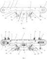
- the vacuum conveyor constituting the embodiment of the present invention is shown schematically in Fig. 1, Fig. 2 and Fig. 3 .
- the conveyor comprises a drive drum 1 and a tension drum 2 which are arranged between two fastening plates 3.
- the transport belt 4 is stretched between the drive drum 1 and the tension drum 2.
- an additional sliding table 5 which remains in contact with the upper inner side of the transport belt 4 is arranged between the drive drum 1 and the tension drum 2.
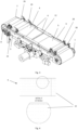
- the transport belt 4 is covered with a microperforation 12, while the sliding table 5 has slots 11 provided on the surface thereof. As shown in Fig.
- the microperforations 12 are in the shape of substantially circular openings of a diameter of 0.3 mm and are arranged in even rows arranged transversely relative to the length of the transport belt 4 over the entire length thereof.
- the openings in the rows are equidistant from each other by 10 mm.
- the rows are located at a fixed distance from each other, which is 5 mm.
- the slots 11 of the sliding table 5 are arranged longitudinally over its entire surface and their width is 5 mm. The distances between the adjacent edges of the individual slots 11 equal 5 mm.
- the slots 11 of the sliding table 5 and the microperforations 12 of the transport belt 4 overlap to provide airflow and immovably maintain transported components. Such an arrangement of the transport belt 4 relative to the sliding table 5 occurs during proper belt guiding when the openings in the transport belt 4 overlap the slots 11 of the sliding table 5.
- the size and arrangement of the openings of the microperforation 12 in the transport belt 4 do not limit the scope of the present invention, and in alternative embodiments, the openings may have a smaller or larger diameter, e.g. 0.2 mm, 0.4 mm or 0.5 mm, their distance from each other in rows may be smaller or larger and may be 5 mm, 7 mm, 13 mm or 15 mm, and the distance between the rows may also be larger or smaller and may be 3 mm, 7 mm or 10 mm, provided that proper belt guidance is maintained.
- a smaller or larger diameter e.g. 0.2 mm, 0.4 mm or 0.5 mm
- their distance from each other in rows may be smaller or larger and may be 5 mm, 7 mm, 13 mm or 15 mm
- the distance between the rows may also be larger or smaller and may be 3 mm, 7 mm or 10 mm, provided that proper belt guidance is maintained.
- the width of the slots 11 in the sliding table 5 and their distances between each other do not constitute a limitation to the present invention, and in alternative embodiments may be smaller or larger, so the width of the slots 11 may be 3 mm or 10 mm, and the distance between the adjacent edges of the slots 11 may be 3 mm or 10 mm, provided that proper belt guiding is maintained.
- the vacuum conveyor is equipped with a drive 7 which ensures its two-way operation.
- the conveyor drive 7 is a servo-motor-type drive which is connected to the drive drum 1 by a belt transmission.
- the belt tension actuator 8 is a pneumatic actuator.
- the type and number of belt tensioning actuators 8 do not limit the scope of the present invention, and in alternative embodiments, the belt tensioning actuators 8 may constitute actuators of another type, e.g. hydraulic actuators, electric actuators, etc., and it is possible to use a larger number of belt tensioning actuators 8, e.g. three, four, provided that the correct guidance and tensioning of the transport belt 4 is maintained.
- connection between the longitudinal axis of the tension drum 2 and the belt tensioning actuator 8 is an articulated connection.
- it is a ball connection, however, it does not limit the scope of the invention, and in alternative embodiments it may constitute another type of articulated connection, while providing compensation of the geometric conditions between functionally connected components such that the transport belt 4 remains tensioned and the web 27 surface of the material does not wrinkle and remains stationary relative to the transport belt 4.
- mounting openings 9 are arranged to which functional rollers are mounted in a configuration suitable for the selected type of punching of pieces from the web 27 of the material.
- the vacuum conveyor according to the present embodiment of the invention is equipped with vacuum means for ensuring proper operation of the device, consisting of holding a web 27 of material on the surface of the transport belt 4 by means of suction thereof.
- the vacuum means comprise three vacuum chambers 10: middle, left and right, arranged on the upper inner side of the transport belt 4 under the sliding table 5.
- a pump is connected to the vacuum chambers 10 to produce a vacuum.
- the number of vacuum chambers 10 does not limit the scope of the invention, and in alternative embodiments, more or less vacuum chambers 10 may be mounted, e.g., one, two, four, provided that it ensures the correct attraction of the transported material on the transport belt 4, so that the transported material does not change its position relative to the transport belt 4.
- the vacuum conveyor comprises a belt guiding sensor 13 which is arranged at the bottom part of the vacuum conveyor. It is responsible for monitoring the position of the transport belt 4 and determining whether it is correct such that the slots 11 on the sliding table 5 overlap the microperforations 12 of the transport belt 4. If the transport belt 4 is shifted too far in one direction such that there is no overlap between the slots 11 on the sliding table 5 and the microperforations 12 of the transport belt 4, the belt guiding sensor 13 sends information to the control system (not shown) and then the actuator pressure control regulator 8 of the belt tension sets the correct pressure value to ensure the desired tension and guidance of the transport belt 4.
- the vacuum conveyor is also equipped with a mechanical cleaning system and a chemical cleaning system.
- the mechanical cleaning system includes two doctor blades: a left doctor blade 14a and a right doctor blade 14b.
- Each doctor blade 14a, 14b at one end is provided with a semi-swing connection and a pressure actuator 15a, 15b to provide independent pressing or releasing of the pressure relative to the surface of the transport belt 4.
- the right doctor blade 14b is pressed (active position) and the left doctor blade 14a is not in contact with the transport belt 4 (rest position).
- the left doctor blade 14a is pressed and the right doctor blade 14b moves to the rest position.
- doctor blades 14a, 14b does not limit the scope of the invention, and in alternative embodiments, more doctor blades 14a, 14b, e.g. three, four, five, may be installed while maintaining effective removal of debris from the transport belt 4.
- angle ⁇ of the inclination of the doctor blades 14a, 14b also does not constitute a limitation of the invention and in alternative embodiments may be more or less, e.g., 20°, 40°, 50°, 90°, provided that it is possible to effectively remove debris from the transport belt 4.
- the pressure actuators 15a, 15b in this embodiment constitute pneumatic actuators, but this is not a limitation of the present invention as in the case of the type of actuators 8 of the belt tensioning.
- doctor blades 14a, 14b are equipped with a geared motor, which gives them a linear lateral movement, transverse to the transport belt 4. This makes it easier to scrape off debris and does not introduce loads when the transport belt 4 is moving. Debris falls into an easily removable container.
- the vacuum conveyor comprises the chemical cleaning system shown in Fig. 1 and Fig. 2 , wherein the second step of debris removal is implemented.
- the chemical cleaning system has a brush roller 17 arranged under the lower outer surface of the transport belt 4. When the transport belt 4 moves clockwise, the brush roller 17 rotates in the same direction, while when the transport belt 4 moves in the opposite direction, the brush roller 17 rotates counter-clockwise.
- the chemical cleaning system comprises an application nozzle 18 that sprays the cleaning agent onto the brush roller 17. It is worth noting that the application nozzle 18 of the cleaning agent is provided with an electrovalve which operates to regulate the feed stream of the cleaning agent and control its frequency.
- the chemical cleaning system further comprises a suction pump 19 that extracts the residue of the cleaning agent, which is then directed to a tank for the residue of the cleaning agent, which is arranged under the vacuum conveyor.
- a suction pump 19 that extracts the residue of the cleaning agent, which is then directed to a tank for the residue of the cleaning agent, which is arranged under the vacuum conveyor.
- four rubber pullers 20 are provided along the transverse axis of the transport belt 4. The rubber pullers 20 are arranged two at a time on the lower outer and inner surface of the transport belt 4. They are provided for collecting excess cleaning agent from the transport belt 4 regardless of the working direction of the vacuum conveyor.
- rubber pullers 20 does not constitute a limitation to the scope of the present invention, and in alternative embodiments, they may be located only on the outer or only on the inner surface of the transport belt 4, and there may be more or fewer of them, e.g., one, two, three, five.
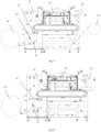
- FIG. 6 An embodiment of the laser punching device according to the present invention is shown in Fig. 6 . Since the laser punching device comprises a conveyor as described in Example 1, a detailed description of the structure thereof will be omitted for clarity of disclosure.
- the laser punching device further comprises a main body 21 to which its individual components are mounted. Additionally, the device is provided with transport rollers 22, arranged on the main body 21, through which the web 27 of material is guided. In the central area of the device there is a laser system 23 which is adapted to punch one layer of the web 27 of material or all of the material through.
- the web 27 of material to be processed is fed to the vacuum conveyor from the unwinder 25, while the finished product is directed to the winder 24.
- Important pieces of the device are the functional rollers, which constitute the guiding roller 26 of the web 27 of material, the waste matrix 32 roller 28, the delamination roller 29, and/or the lamination roller 30. These rollers are mounted in the vacuum conveyor in mounting openings 9 specially designed for this purpose.
- the first type of laser punching is implemented on the device - punching pieces through from the adhesive side.
- the operating mode of the laser punching device depends on the arrangement of the functional rollers and thus on the guiding of the web 27 of material on them.
- the process of punching the pieces through from the adhesive side consists of the web 27 of material being directed over the laser system 23 and is introduced onto the vacuum conveyor in the opposite direction to the direction of transport of the finished pieces (from right to left). In this solution, the transport belt 4 moves counter-clockwise.
- a base 31 is delaminated from the web 27 of material, which in this embodiment constitutes paper coated with silicone.
- the upper layer of material with printed pieces is then sucked onto the transport belt 4 and the base 31 is directed over the laser system 23 over the main web 27 of material.
- the pieces are punched through from the adhesive side with a laser.
- the next step is to separate the waste matrix 32 from the finished pieces.
- the cut-out pieces are transported to the place of reconnection with the previously delaminated base 31.
- the cut-out pieces do not completely change their position due to the vacuum holding them, and the re-lamination is performed on the transport belt 4 after removing the waste matrix 32.
- the base 31, together with the cut labels, is transported in the direction of the winder 24 opposite to the movement direction of the web 27 of material for punching pieces.
- the transport belt 4 moves counter-clockwise.
- the mechanical cleaning system and the chemical cleaning system are actuated, which are described in detail in the first embodiment.
- the tip of the left doctor blade 14a is thus in the active position ensuring that debris is scraped off the surface of the transport belt 4 over its entire width.
- the right blade 14b is displaced by means of the right pressure actuator 15b so that it is not in contact with the surface of the transport belt 4. The scraped off debris falls into the debris container.
- the next cleaning step is the chemical cleaning implemented by the chemical cleaning system.
- a cleaning agent is applied to the brush roller 17 from the application nozzle 18.
- the brush roller 17 then, by rotating counter-clockwise, removes debris from the surface of the transport belt 4.
- the residue of the cleaning agent is collected by the rubber pullers 20 and then directed to the tank.
- FIG. 7 An embodiment of the laser punching device according to the present invention is shown in Fig. 7 . Due to the fact that the laser punching device comprises a vacuum conveyor as described in the Example 1 and other components converging as in the Example 2, a detailed description of the structure thereof will be omitted for clarity of the disclosure.
- punching labels from the web 27 of material from the print side without damaging the base 31 is implemented on the laser punching device, referred to in the art as a kiss cut.
- the movement direction of the web 27 of material and the transport belt 4 is clockwise.
- only the top side of the printed material is punched, without damaging the base 31.
- the waste matrix 32 is separated from the labels.
- the product is a full base 31 with punched labels glued.
- the transport belt 4 moves clockwise.
- the vacuum conveyor is also provided with a mechanical cleaning system and a chemical cleaning system as described in detail in the first embodiment.
- the right doctor blade 14b is pressed against the surface of the transport belt 4.
- the left doctor blade 14a is displaced from the surface of the transport belt 4.
- the scraped off debris falls into the debris container.
- the next cleaning step is the chemical cleaning implemented by the chemical cleaning system.
- the chemical cleaning process proceeds in the same way as in the second example, with the difference that the brush roller 17 rotates in the opposite direction due to a change in the movement direction of the transport belt 4.
- FIG. 8 An embodiment of the laser punching device according to the present invention is shown in Fig. 8 . Due to the fact that the laser punching device comprises a vacuum conveyor as described in the Example 1 and other components essentially converging as in the Example 2 and 3, a detailed description of the structure thereof will be omitted for clarity of the disclosure. It should be emphasized that in this embodiment, the laser punching device does not include a winder 24 as in the second and third examples.
- the laser punching device similarly to the third embodiment, is intended for laser punching labels.
- the cutting of labels through from the print side is implemented on the laser punching device.
- the transport belt 4 moves clockwise, that is, it transports the web 27 of material and the punched labels from its left side to its right side.
- the laser cuts the web 27 of material through (top layer and base 31).
- the waste matrix 32 is separated from the labels.
- the vacuum in the right vacuum chamber 10 is disconnected, as a result of which the ready labels are not attracted to the transport table 4 in this area. This ensures that they can be picked up or sorted from the transport belt 4 in different ways - e.g. by a robot, collected in a container at the end of a vacuum conveyor or transferred by an additional vacuum conveyor.
Landscapes
- Engineering & Computer Science (AREA)
- Mechanical Engineering (AREA)
- Physics & Mathematics (AREA)
- Optics & Photonics (AREA)
- Plasma & Fusion (AREA)
- Cleaning In General (AREA)
- Treatment Of Fiber Materials (AREA)
- Laser Beam Processing (AREA)
Applications Claiming Priority (2)
| Application Number | Priority Date | Filing Date | Title |
|---|---|---|---|
| PL438271A PL247789B1 (pl) | 2021-06-25 | 2021-06-25 | Przenośnik podciśnieniowy, sposób czyszczenia przenośnika podciśnieniowego i urządzenie do laserowego wykrawania zawierające przenośnik podciśnieniowy |
| PCT/IB2022/055817 WO2022269524A1 (en) | 2021-06-25 | 2022-06-23 | Vacuum conveyor, a method for cleaning a vacuum conveyor and a laser punching device comprising a vacuum conveyor |
Publications (3)
| Publication Number | Publication Date |
|---|---|
| EP4359335A1 EP4359335A1 (en) | 2024-05-01 |
| EP4359335C0 EP4359335C0 (en) | 2025-04-30 |
| EP4359335B1 true EP4359335B1 (en) | 2025-04-30 |
Family
ID=82932375
Family Applications (1)
| Application Number | Title | Priority Date | Filing Date |
|---|---|---|---|
| EP22754913.6A Active EP4359335B1 (en) | 2021-06-25 | 2022-06-23 | Vacuum conveyor, a method for cleaning a vacuum conveyor and a laser punching device comprising a vacuum conveyor |
Country Status (3)
| Country | Link |
|---|---|
| EP (1) | EP4359335B1 (pl) |
| PL (1) | PL247789B1 (pl) |
| WO (1) | WO2022269524A1 (pl) |
Families Citing this family (2)
| Publication number | Priority date | Publication date | Assignee | Title |
|---|---|---|---|---|
| CN116872003B (zh) * | 2023-06-25 | 2024-01-26 | 山东通泰橡胶股份有限公司 | 一种节能型橡胶输送带及其加工装置 |
| CN120622172B (zh) * | 2025-08-13 | 2025-10-17 | 江苏源泉新材料科技有限公司 | 一种可自动清洁的浸渍纸运输装置 |
Family Cites Families (3)
| Publication number | Priority date | Publication date | Assignee | Title |
|---|---|---|---|---|
| JP4811238B2 (ja) * | 2006-11-06 | 2011-11-09 | コニカミノルタホールディングス株式会社 | インクジェット記録装置 |
| ATE539985T1 (de) * | 2009-06-03 | 2012-01-15 | Fameccanica Data Spa | Fördervorrichtung für laserbehandlungen |
| DE102018119971B4 (de) * | 2018-08-16 | 2022-03-24 | Jörg Scheffler | Vorrichtung zur Bearbeitung flächiger Elemente |
-
2021
- 2021-06-25 PL PL438271A patent/PL247789B1/pl unknown
-
2022
- 2022-06-23 WO PCT/IB2022/055817 patent/WO2022269524A1/en not_active Ceased
- 2022-06-23 EP EP22754913.6A patent/EP4359335B1/en active Active
Also Published As
| Publication number | Publication date |
|---|---|
| WO2022269524A1 (en) | 2022-12-29 |
| EP4359335C0 (en) | 2025-04-30 |
| PL247789B1 (pl) | 2025-09-01 |
| EP4359335A1 (en) | 2024-05-01 |
| PL438271A1 (pl) | 2022-12-27 |
Similar Documents
| Publication | Publication Date | Title |
|---|---|---|
| EP4359335B1 (en) | Vacuum conveyor, a method for cleaning a vacuum conveyor and a laser punching device comprising a vacuum conveyor | |
| EP3380285B1 (de) | Vorrichtung zum behandeln von substraten | |
| EP0673839B1 (en) | Method and apparatus for handling linerless label material | |
| EP3380284B1 (de) | Vorrichtung zum behandeln von substraten | |
| EP3380282B1 (de) | Vorrichtung zum behandeln von substraten | |
| CN103568468B (zh) | 标签原纸的废纸揭起方法及废纸揭起装置 | |
| EP2125532B1 (de) | Transportvorrichtung | |
| US7934529B2 (en) | Method and apparatus for manufacture and inspection of swatch bearing sheets using a vacuum conveyor | |
| JP6766168B2 (ja) | シート繰出システムおよびシート繰出方法 | |
| US7024976B2 (en) | Automatic cutting of pieces in a sheet material | |
| DE102016209344B4 (de) | Vorrichtung zum Behandeln von Substraten | |
| EP2229324B1 (de) | Verfahren zum etikettieren von behältern sowie etikettierstation | |
| DE102016226175B4 (de) | Vorrichtung zum Behandeln von Substraten | |
| DE102016223226B4 (de) | Vorrichtung zum Behandeln von Substraten | |
| CA2052627C (en) | Apparatus and method for removing a release sheet from a workpiece | |
| US20140231484A1 (en) | Apparatus and method for providing film sheets, application apparatus for populating articles with film sheets | |
| DE102016223225B4 (de) | Vorrichtung zum Behandeln von Substraten | |
| CN104441783A (zh) | 具有配合冲制带的用于冲制标签的设备 | |
| EP1837171A1 (en) | A label production apparatus | |
| CN104271340A (zh) | 包括配备有输送装置的进料台的板状件加工机 | |
| RU2299928C2 (ru) | Машина для обработки полотна, по меньшей мере, с одной вакуумной камерой | |
| CA2468002A1 (en) | High speed mounting and printing for colored chips on a sheet | |
| DE102015223095B4 (de) | Vorrichtung zum Behandeln von Substraten | |
| EP3098018A1 (en) | Singulation conveyor | |
| US5340430A (en) | System for handling a waste web of a web laminate |
Legal Events
| Date | Code | Title | Description |
|---|---|---|---|
| STAA | Information on the status of an ep patent application or granted ep patent |
Free format text: STATUS: UNKNOWN |
|
| STAA | Information on the status of an ep patent application or granted ep patent |
Free format text: STATUS: THE INTERNATIONAL PUBLICATION HAS BEEN MADE |
|
| PUAI | Public reference made under article 153(3) epc to a published international application that has entered the european phase |
Free format text: ORIGINAL CODE: 0009012 |
|
| STAA | Information on the status of an ep patent application or granted ep patent |
Free format text: STATUS: REQUEST FOR EXAMINATION WAS MADE |
|
| 17P | Request for examination filed |
Effective date: 20240123 |
|
| AK | Designated contracting states |
Kind code of ref document: A1 Designated state(s): AL AT BE BG CH CY CZ DE DK EE ES FI FR GB GR HR HU IE IS IT LI LT LU LV MC MK MT NL NO PL PT RO RS SE SI SK SM TR |
|
| DAV | Request for validation of the european patent (deleted) | ||
| DAX | Request for extension of the european patent (deleted) | ||
| GRAP | Despatch of communication of intention to grant a patent |
Free format text: ORIGINAL CODE: EPIDOSNIGR1 |
|
| STAA | Information on the status of an ep patent application or granted ep patent |
Free format text: STATUS: GRANT OF PATENT IS INTENDED |
|
| RIC1 | Information provided on ipc code assigned before grant |
Ipc: B65G 45/24 20060101ALI20241031BHEP Ipc: B65G 45/22 20060101ALI20241031BHEP Ipc: B65G 45/12 20060101ALI20241031BHEP Ipc: B65G 15/30 20060101ALI20241031BHEP Ipc: B23K 26/70 20140101ALI20241031BHEP Ipc: B23K 26/38 20140101ALI20241031BHEP Ipc: B23K 26/08 20140101ALI20241031BHEP Ipc: B65H 20/06 20060101AFI20241031BHEP |
|
| INTG | Intention to grant announced |
Effective date: 20241121 |
|
| GRAS | Grant fee paid |
Free format text: ORIGINAL CODE: EPIDOSNIGR3 |
|
| GRAA | (expected) grant |
Free format text: ORIGINAL CODE: 0009210 |
|
| STAA | Information on the status of an ep patent application or granted ep patent |
Free format text: STATUS: THE PATENT HAS BEEN GRANTED |
|
| AK | Designated contracting states |
Kind code of ref document: B1 Designated state(s): AL AT BE BG CH CY CZ DE DK EE ES FI FR GB GR HR HU IE IS IT LI LT LU LV MC MK MT NL NO PL PT RO RS SE SI SK SM TR |
|
| REG | Reference to a national code |
Ref country code: CH Ref legal event code: EP Ref country code: GB Ref legal event code: FG4D |
|
| REG | Reference to a national code |
Ref country code: DE Ref legal event code: R096 Ref document number: 602022013977 Country of ref document: DE |
|
| REG | Reference to a national code |
Ref country code: IE Ref legal event code: FG4D |
|
| U01 | Request for unitary effect filed |
Effective date: 20250530 |
|
| U07 | Unitary effect registered |
Designated state(s): AT BE BG DE DK EE FI FR IT LT LU LV MT NL PT RO SE SI Effective date: 20250605 |
|
| U20 | Renewal fee for the european patent with unitary effect paid |
Year of fee payment: 4 Effective date: 20250610 |
|
| PG25 | Lapsed in a contracting state [announced via postgrant information from national office to epo] |
Ref country code: ES Free format text: LAPSE BECAUSE OF FAILURE TO SUBMIT A TRANSLATION OF THE DESCRIPTION OR TO PAY THE FEE WITHIN THE PRESCRIBED TIME-LIMIT Effective date: 20250430 |
|
| PG25 | Lapsed in a contracting state [announced via postgrant information from national office to epo] |
Ref country code: GR Free format text: LAPSE BECAUSE OF FAILURE TO SUBMIT A TRANSLATION OF THE DESCRIPTION OR TO PAY THE FEE WITHIN THE PRESCRIBED TIME-LIMIT Effective date: 20250731 Ref country code: NO Free format text: LAPSE BECAUSE OF FAILURE TO SUBMIT A TRANSLATION OF THE DESCRIPTION OR TO PAY THE FEE WITHIN THE PRESCRIBED TIME-LIMIT Effective date: 20250730 |
|
| PG25 | Lapsed in a contracting state [announced via postgrant information from national office to epo] |
Ref country code: PL Free format text: LAPSE BECAUSE OF FAILURE TO SUBMIT A TRANSLATION OF THE DESCRIPTION OR TO PAY THE FEE WITHIN THE PRESCRIBED TIME-LIMIT Effective date: 20250430 |
|
| PG25 | Lapsed in a contracting state [announced via postgrant information from national office to epo] |
Ref country code: HR Free format text: LAPSE BECAUSE OF FAILURE TO SUBMIT A TRANSLATION OF THE DESCRIPTION OR TO PAY THE FEE WITHIN THE PRESCRIBED TIME-LIMIT Effective date: 20250430 |
|
| PG25 | Lapsed in a contracting state [announced via postgrant information from national office to epo] |
Ref country code: RS Free format text: LAPSE BECAUSE OF FAILURE TO SUBMIT A TRANSLATION OF THE DESCRIPTION OR TO PAY THE FEE WITHIN THE PRESCRIBED TIME-LIMIT Effective date: 20250731 |
|
| PG25 | Lapsed in a contracting state [announced via postgrant information from national office to epo] |
Ref country code: IS Free format text: LAPSE BECAUSE OF FAILURE TO SUBMIT A TRANSLATION OF THE DESCRIPTION OR TO PAY THE FEE WITHIN THE PRESCRIBED TIME-LIMIT Effective date: 20250830 |