EP4358338A1 - Netzgekoppeltes betriebssteuerungsverfahren und vorrichtung für ein kombiniertes wärme- und stromsystem mit brennstoffzellen - Google Patents
Netzgekoppeltes betriebssteuerungsverfahren und vorrichtung für ein kombiniertes wärme- und stromsystem mit brennstoffzellen Download PDFInfo
- Publication number
- EP4358338A1 EP4358338A1 EP22845305.6A EP22845305A EP4358338A1 EP 4358338 A1 EP4358338 A1 EP 4358338A1 EP 22845305 A EP22845305 A EP 22845305A EP 4358338 A1 EP4358338 A1 EP 4358338A1
- Authority
- EP
- European Patent Office
- Prior art keywords
- output
- grid
- module
- value
- target value
- Prior art date
- Legal status (The legal status is an assumption and is not a legal conclusion. Google has not performed a legal analysis and makes no representation as to the accuracy of the status listed.)
- Pending
Links
Images


Classifications
-
- H—ELECTRICITY
- H02—GENERATION; CONVERSION OR DISTRIBUTION OF ELECTRIC POWER
- H02J—ELECTRIC POWER NETWORKS; CIRCUIT ARRANGEMENTS OR SYSTEMS FOR SUPPLYING OR DISTRIBUTING ELECTRIC POWER; SYSTEMS FOR STORING ELECTRIC ENERGY
- H02J4/00—Circuit arrangements for mains or distribution networks not specified as AC or DC; Circuit arrangements for mains or distribution networks combining AC and DC sections or sub-networks
-
- H—ELECTRICITY
- H02—GENERATION; CONVERSION OR DISTRIBUTION OF ELECTRIC POWER
- H02J—ELECTRIC POWER NETWORKS; CIRCUIT ARRANGEMENTS OR SYSTEMS FOR SUPPLYING OR DISTRIBUTING ELECTRIC POWER; SYSTEMS FOR STORING ELECTRIC ENERGY
- H02J1/00—Circuit arrangements for DC mains or DC distribution networks
- H02J1/14—Balancing load and power generation in DC networks
-
- H—ELECTRICITY
- H02—GENERATION; CONVERSION OR DISTRIBUTION OF ELECTRIC POWER
- H02J—ELECTRIC POWER NETWORKS; CIRCUIT ARRANGEMENTS OR SYSTEMS FOR SUPPLYING OR DISTRIBUTING ELECTRIC POWER; SYSTEMS FOR STORING ELECTRIC ENERGY
- H02J3/00—Circuit arrangements for AC mains or AC distribution networks
- H02J3/38—Arrangements for feeding a single network from two or more generators or sources in parallel; Arrangements for feeding already energised networks from additional generators or sources in parallel
- H02J3/46—Controlling the sharing of generated power between the generators, sources or networks
- H02J3/48—Controlling the sharing of active power
-
- H—ELECTRICITY
- H02—GENERATION; CONVERSION OR DISTRIBUTION OF ELECTRIC POWER
- H02J—ELECTRIC POWER NETWORKS; CIRCUIT ARRANGEMENTS OR SYSTEMS FOR SUPPLYING OR DISTRIBUTING ELECTRIC POWER; SYSTEMS FOR STORING ELECTRIC ENERGY
- H02J2101/00—Supply or distribution of decentralised, dispersed or local electric power generation
- H02J2101/20—Dispersed power generation using renewable energy sources
- H02J2101/30—Fuel cells
-
- Y—GENERAL TAGGING OF NEW TECHNOLOGICAL DEVELOPMENTS; GENERAL TAGGING OF CROSS-SECTIONAL TECHNOLOGIES SPANNING OVER SEVERAL SECTIONS OF THE IPC; TECHNICAL SUBJECTS COVERED BY FORMER USPC CROSS-REFERENCE ART COLLECTIONS [XRACs] AND DIGESTS
- Y02—TECHNOLOGIES OR APPLICATIONS FOR MITIGATION OR ADAPTATION AGAINST CLIMATE CHANGE
- Y02E—REDUCTION OF GREENHOUSE GAS [GHG] EMISSIONS, RELATED TO ENERGY GENERATION, TRANSMISSION OR DISTRIBUTION
- Y02E60/00—Enabling technologies; Technologies with a potential or indirect contribution to GHG emissions mitigation
- Y02E60/30—Hydrogen technology
- Y02E60/50—Fuel cells
Definitions
- the present invention relates the technical field of fuel cell power supply and heat supply, in particular to a grid-connected operation control method and device for a combined heat and power system.
- hydrogen energy has the advantages such as harmless emission, renewability and a high energy utilization rate.
- the fuel of a residential fuel cell system based on hydrogen energy has the characteristic of generating electricity and heat at the same time, and can control a working state of the fuel cell by controlling the output heat and electricity.
- impedance units are additionally provided and then inverters are connected, but such methods only allow for control of the inverters with one degree of freedom, and cannot control reactive power components.
- An object of the present disclosure is to provide a grid-connected operation control method and device for a combined heat and power system.
- the present disclosure provides a grid-connected operation control method for a fuel cell combined heat and power system
- the fuel cell combined heat and power system comprises a thermoelectric module, a DC/DC conversion module, a DC/AC inverter module and a thermal management module;
- the thermoelectric module is connected to a DC bus through the DC/DC conversion module, andthe inverter module is connected to the DC bus;
- an output end of the DC/DC conversion module is connected to a DC load of a user, and an output end of the inverter unit is connected to an AC load of the user and a grid;
- generating a DC/AC inverter output voltage target value according to the AC grid voltage parameter, and controlling a switching tube of the DC/AC inverter module to be turned on or off according to the output voltage target value further comprises the steps:
- "acquiring target output voltages V ⁇ ref and V ⁇ ref in an ⁇ coordinate system according to the AC grid voltage parameters, the DC bus voltage target value and the DC bus voltage measured value” further comprises the steps:
- determining a current target value i ⁇ ref in the ⁇ coordinate axis according to the first difference value, and determining a current target value i ⁇ ref in the ⁇ coordinate axis according to a grid voltage further comprises the steps:
- a phase-locked loop is used to calculate an angle required for transformation between the dq coordinate system and the ⁇ coordinate system based on measured grid voltages vsa, vsb and vsc in the abc coordinate system.
- controlling a switching-off tube of the DC/DC conversion module to be turned on or off according to the output power target value further comprises: outputting the power target value to acquire an output current target value iref;
- controlling a switching-off tube of the DC/DC conversion module to be turned on or off according to the output power target value further comprises: judging whether the heat supply temperature exceeds an allowable range, if exceeding the allowable range, generating a target output power correction coefficient K according to a temperature difference between a target temperature and a measured temperature, and correcting the output power target value to K times an original value.
- "generating a target output power correction coefficient K according to a temperature difference between the target temperature and a measured temperature” further comprises: inputting the temperature difference into the PI regulator, and adding 1 to an output value of the PI regulator to acquire the correction coefficient K.
- the present disclosure further provides a grid-connected operation control device for a fuel cell combined heat and power system, characterized in that the control device comprises a thermoelectric module, a DC/DC conversion module, a DC/AC inverter module, a thermal management module, a detection unit, a target power calculation module and a regulator;
- Fig. 1 is a flowchart of a grid-connected operation control method for a fuel cell combined heat and power system according to a first embodiment of the present invention, which can be applied to a grid-connected operation control scenario based on the fuel cell combined heat and power system, and the method can be executed by a functional module configured with specific combined heat and power system software and hardware.
- the fuel cell combined heat and power system includes a thermoelectric module PEMFC 702, a DC/DC conversion module 704, a DC/AC inverter module 706 and a thermal management module 708.
- the thermoelectric module is connected to a DC bus through the DC/DC conversion module 704, and the inverter module 706 is connected to the DC bus.
- An output end of the DC/DC conversion module 704 is connected to a DC load of a user, and the output end of an inverter module is connected to a AC load of the user and a grid.
- the thermoelectric module 702 may be a fuel cell system.
- the fuel cell system uses clean energy such as hydrogen or methane as fuel, and generates a higher calorific value while generating electricity. Therefore, the combined heat and power system can realize heat supply, AC power supply and DC power supply.
- the combined heat and power system can simultaneously supply heat and power.
- the grid-connected mode means that the thermoelectric system is connected in parallel with the grid while supplying power and heat to the user.
- the thermoelectric system can absorb electric energy of the grid when the function is insufficient, and can feed electricity to the grid when the electric energy of the system is surplus.
- an island operation control method for a combined heat and power system specifically includes the following steps.
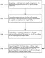
- step 102 a real-time heat supply temperature of the thermoelectric module and an AC grid voltage parameter are acquired.
- the heat supply temperature is the temperature of a hot water pipe in the thermoelectric module, and the hot water temperature may be a temperature of a water outlet close to the thermal management module or a temperature of a water inlet close to a user side.
- a temperature sensor is arranged in the thermal management module to monitor the water temperature in real time.
- the system is provided with a detection module for detecting the AC grid voltage parameter of the user.
- the detection module can detect an a-axis voltage, a b-axis voltage and a c-axis voltage in a three-phase current abc coordinate system of the grid.
- step 104 the output power of a fuel cell module is corrected according to the real-time heat supply temperature to acquire an output power target value.
- step 106 a switching tube of the DC/DC conversion module is controlled to be turned on or off according to the output power target value.
- step 108 a DC/AC three-phase voltage target value is generated according to the AC grid voltage parameter, and a switching tube of the DC/AC inverter module is controlled to be turned on or off according to the three-phase voltage target value.
- step 106 and step 108 may be executed at the same time to meet the DC load and the AC load of the user simultaneously.
- Step 102 to step 108 correct the output power target value of the fuel cell and the voltage output value based on the hot water temperature and grid-connected voltage feedback, and the system heat output follows user requirements and the voltage output can follow the user requirements.
- the DC bus is used to supply the DC provided by the DC/DC module to the DC power load on the user side.
- the DC bus supplies the DC provided by the DC/DC module to the DC/AC inverter module.
- the grid voltage on the user side and the temperature parameter are used as external input parameters of the system to regulate the output power of the thermoelectric module, thereby realizing heat requirements on the user side and load requirements of the grid.
- the output power of the thermoelectric module is dynamically adjusted according to load transformation of the user.
- the target output power of the thermoelectric module which is positively related to heat consuming requirements of the user and the AC load requirements, is dynamically adjusted along with the transformation of the temperature and the grid voltage value.
- the system changes a bus output current according to the real-time temperature, the target output power after the change of the real-time temperature and the loads of the user, so that the output power of a hotspot module follows the output power target value.
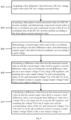
- Fig. 2 is a preferred example of the above step 108, which serves as a sub-step of step 108. As shown in Fig. 2 , step 108 further includes the following steps.
- step 202 real-time output current parameters of the DC/AC inverter module are acquired.
- the real-time current parameters of the DC/AC inverter module include real-time output current parameters in the abc coordinate system.
- the real-time output current parameters include an a-axis current ia, a b-axis current ib and a c-axis current ic.
- the currents ia, ib and ic are the current values of the input end of an inductor device of the inverter module, respectively.
- step 204 a DC bus voltage target value and a DC bus voltage measured value are acquired.
- the DC bus voltage value and the DC bus voltage target value may be detected by the thermoelectric module and may also be provided by the DC/DC conversion module.
- the DC bus voltage target value is a fixed value designed by the system, and is related to a DC load of the system.
- step 206 the DC/AC output voltage is corrected according to the real-time output current parameters of the DC/AC inverter module, the AC grid voltage parameter, the DC bus voltage target value and the DC bus voltage measured value.
- a DC/AC output voltage target value Vref is generated through calculation by a regulator.
- the output voltage target value includes triaxial voltages Va, Vb and Vc, and the triaxial voltages generate a switching tube driving signal through a switching tube driving module.
- Fig. 3 is a flowchart of generating the DC/AC output voltage target value through calculation of the regulator, and Fig. 3 is also a preferred example of the above step 206, which serves as a sub-step of step 206. As shown in Fig. 3 , step 108 further includes the following steps.
- step 302 target output voltages V ⁇ ref and V ⁇ ref in an ⁇ coordinate system are acquired according to the AC grid voltage parameter, the DC bus voltage target value and the DC bus voltage measured value.
- step 304 the output voltages Va, Vb and Vc in the abc coordinate system are acquired according to the output voltages V ⁇ and V ⁇ .
- an SPWM driver controls the switching tube to be turned on or off according to the output voltages Va, Vb and Vc.
- phase angles required for coordinate transformation in steps 302, 304 and 306 are acquired by a current signal of the DC/AC inverter module.
- step 302 is a preferred example of the above step 302, which serves as a sub-step of step 302. As shown in Fig. 4 , step 302 further includes the following steps.
- step 402 a first difference value between the DC bus voltage target value and the DC bus voltage measured value is acquired.
- step 404 a three-phase current measured value of the DC/AC inverter module is acquired, and a measured current value i ⁇ in an ⁇ coordinate axis and a measured current value i ⁇ in a ⁇ coordinate axis of the DC/AC inverter module are acquired according to the three-phase current measured value.
- a current target value i ⁇ ref in the ⁇ coordinate axis is determined according to the first difference value, and a current target value i ⁇ ref in the ⁇ coordinate axis is determined according to the grid voltage.
- the first difference value is converted into a d-axis current target value idref in a dq coordinate system through a PI regulator; and a q-axis current target value iqref is determined according to the grid voltage.
- the PI regulator is a proportional-integral controller, and the proportional-integral controller performs proportional amplification and integral operation on the first difference value and sums the two results to acquire the target value idref.
- the current values idref and iqref in the dq coordinate system are converted into the current values i ⁇ ref and i ⁇ ref in the ⁇ coordinate system.
- the coordinate transformation method among the three-phase coordinate system, the dq coordinate system and the ⁇ coordinate system is a common technical means for those skilled in the art, and will not be repeated herein.
- step 408 the difference value between the measured current value i ⁇ and the current target value i ⁇ ref is calculated to acquire a second difference value, and the second difference value is converted into an ⁇ -axis output voltage V ⁇ by using a PR regulator; and the ⁇ -axis output voltage V ⁇ and the corresponding values of AC grid measured voltages Vsa, Vsb and Vsc in the ⁇ coordinate system are summed to acquire the ⁇ -axis target output voltage V ⁇ ref.
- step 410 the difference value between the measured current value i ⁇ and the current target value i ⁇ ref is calculated to acquire a third difference value; and the third difference value is converted into a voltage V ⁇ in a ⁇ output axis by using the PR regulator.
- the ⁇ -axis output voltage V ⁇ and the corresponding values of the AC grid measured voltages Vsa, Vsb and Vsc in the ⁇ coordinate system are summed to acquire an target output voltage V ⁇ ref of the ⁇ -axis output voltage V ⁇ .
- the three-phase coordinate system and the ⁇ coordinate system perform coordinate transformation on the three-phase current output by the output end of the DC/AC inverter module to acquire the measured current values i ⁇ and i ⁇ .
- Fig. 5 is a preferred example of step 106, which serves as a sub-step of step 302. As shown in Fig. 4 , step 106 further includes the following steps.
- step 502 the power target value is output to acquire an output current target value iref.
- the output target current value iref is equal to Pref/v, wherein v is an output end voltage of the thermoelectric module.
- step 504 a difference value between the target value and the measured current value is calculated to acquire a fourth difference value, and the fourth difference value is input to the PI regulator.
- step 506 an output signal of the PI regulator is compared with a carrier signal to acquire a switching tube control signal of the DC/DC conversion module.
- thermoelectric module Due to the control flow 502-504, the output power of the thermoelectric module follows the heat consuming requirements of the users.
- Fig. 6 is yet another preferred example of the above step 106, which serves as a sub-step of step 106. As shown in Fig. 6 , steps 612-616 are the same as steps 502-506 in Fig. 5 , and will not be repeated again.
- a target power correction coefficient is acquired according to whether the temperature exceeds a set range (the temperature is too high or too low), so that the target power increases or decreases along with the increase or decrease of the temperature.
- the specific steps include the following steps.
- step 602 a temperature difference between a target temperature and a measured temperature is acquired.
- step 604 the temperature difference is input into the PI regulator.
- step 606 the correction coefficient K is set to be equal to the output value of the PI regulator plus 1.
- step 608 when the measured temperature exceeds an upper limit of the range in step 608, the control flow jumps to step 612.
- the control flow jumps to step 610.
- the coefficient k is greater than one, and the output power increase of a hotspot module system can follow the heat requirements of the users.
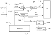
- Fig. 7 provides a grid-connected operation control device for a fuel cell combined heat and power system.
- the control device can execute the above hotspot combined heat and power control method according to any embodiment of the present invention, and has corresponding functional modules for executing the method and beneficial effects.
- the control device for the fuel cell combined heat and power system includes a thermoelectric module (PEMFC) 702, a DC/DC conversion module 704, a DC/AC inverter module 706, a thermal management module 708 and a regulator 710.
- the thermoelectric module is connected to a DC bus through the DC/DC conversion module 704, an output end of the DC/DC module is connected to a DC load of a user 712, and an output end of the DC/AC inverter module 706 is connected to a AC load of the user and a grid.
- a detection unit 714 is used to acquire a real-time heat supply temperature of the thermoelectric module, a DC bus voltage parameter and an AC grid voltage parameter.
- a target power calculation module 716 is configured to calculate a thermoelectric output power target value according to the real-time heat supply temperature.
- the target power estimation module calculates the target power that should be output by the thermoelectric module according to factors such as water consumption per unit time, water temperature, water specific heat capacity and heat loss.
- the regulator 710 generates a switching tube control signal of the DC/AC inverter module according to a measured bus voltage and a grid measured voltage, and generates a switching tube control signal of the DC/DC conversion module according to the real-time heat supply temperature and the output power target value of the thermoelectric module.
- a switching tube driving unit is arranged in the DC/DC conversion module 704 and the DC/AC inverter module 706.
- the switching tube driving unit receives a switching control signal generated by the regulator 710, and controls a power switching tube in the DC/AC inverter module 706 or the DC/DC conversion module 704 according to the control signal.
- the DC/DC conversion module and the DC/AC inverter module are connected in series.
- the regulator is divided into a regulator of the DC/AC inverter module 706 and a regulator of the DC/DC conversion module 704.
- the active and reactive components are decoupled with two degrees of freedom and the control of the reactive components is further realized.
- the regulator 710 is divided into a regulator 800 of the DC/AC inverter module and a regulator 900 of a DC/DC rectifier module.
- Fig. 8 shows the regulator of the DC/DC inverter module, and Fig. 8 shows the regulator of the DC/AC inverter module.
- the regulator of the DC/AC inverter module includes first to fifth adders (numbered p1-p5 in the figure) PI regulators, PR regulators 802 and 802', a cyclic phase locker pll804, a first abc/ ⁇ coordinate system coordinate converter 804, a second abc/ ⁇ and dq/ ⁇ coordinate converter 806, an ⁇ /abc coordinate converter 808, a PI regulator 810, a first PR regulator and a second PR regulator.
- the switching tube control signal of the regulator for the DC/AC inverter includes the follows.
- the difference value Vdcref between the measured DC bus voltage Vdc and its target value is calculated, the difference value is input to calculate a d-axis current target value idref in the dq coordinate system through the PI regulator 810, and a q-axis current target value iqref is determined according to a grid instruction or a grid voltage; and the dq-axis current target values idref and iqref are input into the dq/ ⁇ coordinate converter 806, to calculate the current target values i ⁇ ref and i ⁇ ref in the ⁇ coordinate system.
- the current signal at the input end of a filter inductor L is sampled by feedforward control to acquire three-phase output currents ia, ib and ic, which are input to the abc/ ⁇ coordinate converter 804, and the sampled values ia, ib and ic are converted into the current values i ⁇ and i ⁇ in the ⁇ coordinate system through the abc/ ⁇ coordinate converter 804.
- difference values between the above i ⁇ ref and i ⁇ ref and between the above i ⁇ and i ⁇ are calculated, and according to the difference values, corresponding voltage values V ⁇ and V ⁇ in the ⁇ coordinate system are calculated through the PR regulators 802 and 802'.
- the voltage values V ⁇ and V ⁇ are respectively added with the measured three-phase grid voltages vsa, vsb and vsc through corresponding components of the adders p4 and p5 in the ⁇ coordinate system, and the inverter output voltage target values V ⁇ ref and V ⁇ ref are calculated.
- the inverter three-phase voltage target values va, vb and vc are calculated through ⁇ /abc coordinate transformation, and finally the inverter switching tube control signal is calculated through the SPWM.
- the inverter switching tube control signal is sent to the switching tube, so that the inverter output can be dynamically adjusted along with the fluctuation of the grid.
- the regulator of the DC/DC inverter module includes first to third adders (numbered p6-p8 in the figure), a first PI regulator 902, a second PI regulator 904, an enabler 906, a first multiplier 908, a second multiplier 910 and a comparator 912.
- the switching tube is controlled. Specifically, the output current target value iref is calculated by dividing the output power target value Pref of the fuel cell by the end voltage vc thereof through the second multiplier 910; the target value iref is input to the adder P8 to calculate a difference value between it and the measured output current ic and the difference value is used as the input of the second PI regulator 904; and the output of the second PI regulator 904 is compared with a carrier signal to calculate the switching tube control signal.
- the function of correcting the target power according to the temperature range of hot water is also provided.
- the hot water temperature T exceeds an allowable range (too low or too high)
- the "enabling control" signal of the enabler 906 is 1.
- a difference value between the actual hot water temperature T and its target value Tref is calculated, the temperature difference is input the first PI regulator 902 to calculate a result which is added with 1 to acquire the correction coefficient k of the output power target value of the fuel cell; and k and the target power are input to the multiplier to correct the target power, i.e., kPref, as the final output power target value of the fuel cell.
- a closed loop is formed between the current and voltage output by the fuel cell and the current, voltage and hot water requirements on the user side, and the transformation requirements can be responded by monitoring the temperature to correct the target power value.
- the feedforward control is applied to realize rapid response.
- the PR regulator is used to perform closed-loop control on the current in the ⁇ coordinate system, which avoids complicated coordinate transformation and decoupling control and improves the dynamic performance of the system.
- the application of the feedforward control realizes the rapid response of the inverter output voltage when the grid voltage drops, which avoids the occurrence of an inverter surge current, and is beneficial to the improvement of system stability.
- the active components and reactive components can be decoupled.
Landscapes
- Engineering & Computer Science (AREA)
- Power Engineering (AREA)
- Supply And Distribution Of Alternating Current (AREA)
- Fuel Cell (AREA)
Applications Claiming Priority (2)
| Application Number | Priority Date | Filing Date | Title |
|---|---|---|---|
| CN202110819601.5A CN115642626A (zh) | 2021-07-20 | 2021-07-20 | 一种燃料电池热电联供系统并网运行控制方法和装置 |
| PCT/CN2022/106446 WO2023001140A1 (zh) | 2021-07-20 | 2022-07-19 | 一种燃料电池热电联供系统并网运行控制方法和装置 |
Publications (2)
| Publication Number | Publication Date |
|---|---|
| EP4358338A1 true EP4358338A1 (de) | 2024-04-24 |
| EP4358338A4 EP4358338A4 (de) | 2024-10-09 |
Family
ID=84939336
Family Applications (1)
| Application Number | Title | Priority Date | Filing Date |
|---|---|---|---|
| EP22845305.6A Pending EP4358338A4 (de) | 2021-07-20 | 2022-07-19 | Netzgekoppeltes betriebssteuerungsverfahren und vorrichtung für ein kombiniertes wärme- und stromsystem mit brennstoffzellen |
Country Status (3)
| Country | Link |
|---|---|
| EP (1) | EP4358338A4 (de) |
| CN (1) | CN115642626A (de) |
| WO (1) | WO2023001140A1 (de) |
Families Citing this family (1)
| Publication number | Priority date | Publication date | Assignee | Title |
|---|---|---|---|---|
| CN120565738B (zh) * | 2025-07-31 | 2025-10-14 | 山东国创燃料电池技术创新中心有限公司 | 一种燃料电池发电系统及其的控制方法 |
Family Cites Families (7)
| Publication number | Priority date | Publication date | Assignee | Title |
|---|---|---|---|---|
| JP2008300076A (ja) * | 2007-05-29 | 2008-12-11 | Toshiba Fuel Cell Power Systems Corp | 燃料電池制御装置 |
| WO2010116609A1 (ja) * | 2009-03-30 | 2010-10-14 | パナソニック株式会社 | 燃料電池システムおよびその運転方法 |
| JP6154256B2 (ja) * | 2013-09-10 | 2017-06-28 | 京セラ株式会社 | 燃料電池システム及び燃料電池システムの運転方法 |
| CN110525237A (zh) * | 2019-08-30 | 2019-12-03 | 奇瑞商用车(安徽)有限公司 | 电动汽车燃料电池的热电联供系统及其控制方法 |
| CN111259610B (zh) * | 2020-02-21 | 2021-04-16 | 山东大学 | 一种热电联供系统稳态等效电路建立方法及系统 |
| CN111614120A (zh) * | 2020-05-29 | 2020-09-01 | 江苏铧德氢能源科技有限公司 | 一种pem燃料电池chp并网控制系统及其控制方法 |
| CN111639824B (zh) * | 2020-06-20 | 2022-05-24 | 东北电力大学 | 一种含电转气的区域综合能源系统热电优化调度方法 |
-
2021
- 2021-07-20 CN CN202110819601.5A patent/CN115642626A/zh active Pending
-
2022
- 2022-07-19 EP EP22845305.6A patent/EP4358338A4/de active Pending
- 2022-07-19 WO PCT/CN2022/106446 patent/WO2023001140A1/zh not_active Ceased
Also Published As
| Publication number | Publication date |
|---|---|
| CN115642626A (zh) | 2023-01-24 |
| WO2023001140A1 (zh) | 2023-01-26 |
| EP4358338A4 (de) | 2024-10-09 |
Similar Documents
| Publication | Publication Date | Title |
|---|---|---|
| US8848400B2 (en) | System and method for reactive power regulation | |
| KR101699410B1 (ko) | 전력 변환 장치를 구비한 복합 발전 시스템 | |
| JP4680102B2 (ja) | 電力変換装置 | |
| JP5408889B2 (ja) | 電力変換装置 | |
| US9350261B2 (en) | Power converter apparatus applied to wind power generation system | |
| US8369117B2 (en) | Power conversion system for eliminating low frequency ripple current and control method thereof | |
| US7948118B2 (en) | Uninterruptible power supply and method for implementing said power supply | |
| JP2010178495A (ja) | 電力変換装置、及び電力変換システム | |
| EP4358338A1 (de) | Netzgekoppeltes betriebssteuerungsverfahren und vorrichtung für ein kombiniertes wärme- und stromsystem mit brennstoffzellen | |
| JP2014192992A (ja) | 無効電力比率制御器、無効電力比率制御方法、およびこれを用いた発電システム | |
| JP2017189028A (ja) | 分散型電源の制御方法及び制御装置 | |
| WO2022267369A1 (zh) | 热电联供系统及其孤岛运行控制方法、装置 | |
| JP7136368B2 (ja) | 電力変換装置 | |
| CN120357526A (zh) | 一种交直流接入柔性互联装置的控制方法及系统 | |
| WO2022185614A1 (ja) | インバータ、並列インバータシステム、及び、インバータの制御方法 | |
| KR102691036B1 (ko) | 전력 변환 장치의 전력 제어 시스템 및 방법 | |
| CN111817346B (zh) | 风电场启动辅助供电系统 | |
| Hammoud et al. | Computationally efficient model predictive direct power control with online finite set model inductance estimation technique for grid-connected photovoltaic inverters | |
| CN212462806U (zh) | 辅助风电场启动的供电系统 | |
| Ray et al. | Smart control strategy for a DC microgrid | |
| KR101027937B1 (ko) | 무변압기형 계통연계 태양광 발전 시스템의 전력변환장치 | |
| US20250163596A1 (en) | Electrolyzer power control with harmonic absorption | |
| CN110880768A (zh) | 一种基于svg的钻井平台柴油发电系统稳压稳频装置及方法 | |
| JP7700499B2 (ja) | 分散電源の制御装置、制御プログラム、及び分散電源システム | |
| TW201539930A (zh) | 智慧型微電網電力品質管理的操作系統 |
Legal Events
| Date | Code | Title | Description |
|---|---|---|---|
| STAA | Information on the status of an ep patent application or granted ep patent |
Free format text: STATUS: THE INTERNATIONAL PUBLICATION HAS BEEN MADE |
|
| PUAI | Public reference made under article 153(3) epc to a published international application that has entered the european phase |
Free format text: ORIGINAL CODE: 0009012 |
|
| STAA | Information on the status of an ep patent application or granted ep patent |
Free format text: STATUS: REQUEST FOR EXAMINATION WAS MADE |
|
| 17P | Request for examination filed |
Effective date: 20240119 |
|
| AK | Designated contracting states |
Kind code of ref document: A1 Designated state(s): AL AT BE BG CH CY CZ DE DK EE ES FI FR GB GR HR HU IE IS IT LI LT LU LV MC MK MT NL NO PL PT RO RS SE SI SK SM TR |
|
| REG | Reference to a national code |
Ref country code: DE Ref legal event code: R079 Free format text: PREVIOUS MAIN CLASS: H02J0003320000 Ipc: H02J0004000000 |
|
| A4 | Supplementary search report drawn up and despatched |
Effective date: 20240905 |
|
| RIC1 | Information provided on ipc code assigned before grant |
Ipc: H02J 1/14 20060101ALI20240830BHEP Ipc: H02J 3/48 20060101ALI20240830BHEP Ipc: H02J 4/00 20060101AFI20240830BHEP |
|
| DAV | Request for validation of the european patent (deleted) | ||
| DAX | Request for extension of the european patent (deleted) |