EP4357741A1 - Method and system for measuring spectral reflectivity - Google Patents
Method and system for measuring spectral reflectivity Download PDFInfo
- Publication number
- EP4357741A1 EP4357741A1 EP22824171.7A EP22824171A EP4357741A1 EP 4357741 A1 EP4357741 A1 EP 4357741A1 EP 22824171 A EP22824171 A EP 22824171A EP 4357741 A1 EP4357741 A1 EP 4357741A1
- Authority
- EP
- European Patent Office
- Prior art keywords
- spectrum
- ambient light
- target
- measured
- wavelength
- Prior art date
- Legal status (The legal status is an assumption and is not a legal conclusion. Google has not performed a legal analysis and makes no representation as to the accuracy of the status listed.)
- Pending
Links
Images



Classifications
-
- G—PHYSICS
- G01—MEASURING; TESTING
- G01J—MEASUREMENT OF INTENSITY, VELOCITY, SPECTRAL CONTENT, POLARISATION, PHASE OR PULSE CHARACTERISTICS OF INFRARED, VISIBLE OR ULTRAVIOLET LIGHT; COLORIMETRY; RADIATION PYROMETRY
- G01J3/00—Spectrometry; Spectrophotometry; Monochromators; Measuring colours
- G01J3/28—Investigating the spectrum
- G01J3/42—Absorption spectrometry; Double beam spectrometry; Flicker spectrometry; Reflection spectrometry
-
- G—PHYSICS
- G01—MEASURING; TESTING
- G01J—MEASUREMENT OF INTENSITY, VELOCITY, SPECTRAL CONTENT, POLARISATION, PHASE OR PULSE CHARACTERISTICS OF INFRARED, VISIBLE OR ULTRAVIOLET LIGHT; COLORIMETRY; RADIATION PYROMETRY
- G01J3/00—Spectrometry; Spectrophotometry; Monochromators; Measuring colours
- G01J3/02—Details
- G01J3/0205—Optical elements not provided otherwise, e.g. optical manifolds, diffusers, windows
- G01J3/0218—Optical elements not provided otherwise, e.g. optical manifolds, diffusers, windows using optical fibers
-
- G—PHYSICS
- G01—MEASURING; TESTING
- G01J—MEASUREMENT OF INTENSITY, VELOCITY, SPECTRAL CONTENT, POLARISATION, PHASE OR PULSE CHARACTERISTICS OF INFRARED, VISIBLE OR ULTRAVIOLET LIGHT; COLORIMETRY; RADIATION PYROMETRY
- G01J3/00—Spectrometry; Spectrophotometry; Monochromators; Measuring colours
- G01J3/02—Details
- G01J3/0275—Details making use of sensor-related data, e.g. for identification of sensor parts or optical elements
-
- G—PHYSICS
- G01—MEASURING; TESTING
- G01J—MEASUREMENT OF INTENSITY, VELOCITY, SPECTRAL CONTENT, POLARISATION, PHASE OR PULSE CHARACTERISTICS OF INFRARED, VISIBLE OR ULTRAVIOLET LIGHT; COLORIMETRY; RADIATION PYROMETRY
- G01J3/00—Spectrometry; Spectrophotometry; Monochromators; Measuring colours
- G01J3/02—Details
- G01J3/0278—Control or determination of height or angle information for sensors or receivers
-
- G—PHYSICS
- G01—MEASURING; TESTING
- G01J—MEASUREMENT OF INTENSITY, VELOCITY, SPECTRAL CONTENT, POLARISATION, PHASE OR PULSE CHARACTERISTICS OF INFRARED, VISIBLE OR ULTRAVIOLET LIGHT; COLORIMETRY; RADIATION PYROMETRY
- G01J3/00—Spectrometry; Spectrophotometry; Monochromators; Measuring colours
- G01J3/02—Details
- G01J3/0289—Field-of-view determination; Aiming or pointing of a spectrometer; Adjusting alignment; Encoding angular position; Size of measurement area; Position tracking
-
- G—PHYSICS
- G01—MEASURING; TESTING
- G01J—MEASUREMENT OF INTENSITY, VELOCITY, SPECTRAL CONTENT, POLARISATION, PHASE OR PULSE CHARACTERISTICS OF INFRARED, VISIBLE OR ULTRAVIOLET LIGHT; COLORIMETRY; RADIATION PYROMETRY
- G01J3/00—Spectrometry; Spectrophotometry; Monochromators; Measuring colours
- G01J3/02—Details
- G01J3/0297—Constructional arrangements for removing other types of optical noise or for performing calibration
-
- G—PHYSICS
- G01—MEASURING; TESTING
- G01J—MEASUREMENT OF INTENSITY, VELOCITY, SPECTRAL CONTENT, POLARISATION, PHASE OR PULSE CHARACTERISTICS OF INFRARED, VISIBLE OR ULTRAVIOLET LIGHT; COLORIMETRY; RADIATION PYROMETRY
- G01J3/00—Spectrometry; Spectrophotometry; Monochromators; Measuring colours
- G01J3/28—Investigating the spectrum
- G01J3/2823—Imaging spectrometer
-
- G—PHYSICS
- G01—MEASURING; TESTING
- G01N—INVESTIGATING OR ANALYSING MATERIALS BY DETERMINING THEIR CHEMICAL OR PHYSICAL PROPERTIES
- G01N21/00—Investigating or analysing materials by the use of optical means, i.e. using sub-millimetre waves, infrared, visible or ultraviolet light
- G01N21/17—Systems in which incident light is modified in accordance with the properties of the material investigated
- G01N21/25—Colour; Spectral properties, i.e. comparison of effect of material on the light at two or more different wavelengths or wavelength bands
-
- G—PHYSICS
- G01—MEASURING; TESTING
- G01N—INVESTIGATING OR ANALYSING MATERIALS BY DETERMINING THEIR CHEMICAL OR PHYSICAL PROPERTIES
- G01N21/00—Investigating or analysing materials by the use of optical means, i.e. using sub-millimetre waves, infrared, visible or ultraviolet light
- G01N21/17—Systems in which incident light is modified in accordance with the properties of the material investigated
- G01N21/25—Colour; Spectral properties, i.e. comparison of effect of material on the light at two or more different wavelengths or wavelength bands
- G01N21/27—Colour; Spectral properties, i.e. comparison of effect of material on the light at two or more different wavelengths or wavelength bands using photo-electric detection ; circuits for computing concentration
- G01N21/274—Calibration, base line adjustment, drift correction
-
- G—PHYSICS
- G01—MEASURING; TESTING
- G01N—INVESTIGATING OR ANALYSING MATERIALS BY DETERMINING THEIR CHEMICAL OR PHYSICAL PROPERTIES
- G01N21/00—Investigating or analysing materials by the use of optical means, i.e. using sub-millimetre waves, infrared, visible or ultraviolet light
- G01N21/17—Systems in which incident light is modified in accordance with the properties of the material investigated
- G01N21/25—Colour; Spectral properties, i.e. comparison of effect of material on the light at two or more different wavelengths or wavelength bands
- G01N21/31—Investigating relative effect of material at wavelengths characteristic of specific elements or molecules, e.g. atomic absorption spectrometry
-
- G—PHYSICS
- G01—MEASURING; TESTING
- G01J—MEASUREMENT OF INTENSITY, VELOCITY, SPECTRAL CONTENT, POLARISATION, PHASE OR PULSE CHARACTERISTICS OF INFRARED, VISIBLE OR ULTRAVIOLET LIGHT; COLORIMETRY; RADIATION PYROMETRY
- G01J3/00—Spectrometry; Spectrophotometry; Monochromators; Measuring colours
- G01J3/28—Investigating the spectrum
- G01J2003/2866—Markers; Calibrating of scan
-
- G—PHYSICS
- G01—MEASURING; TESTING
- G01J—MEASUREMENT OF INTENSITY, VELOCITY, SPECTRAL CONTENT, POLARISATION, PHASE OR PULSE CHARACTERISTICS OF INFRARED, VISIBLE OR ULTRAVIOLET LIGHT; COLORIMETRY; RADIATION PYROMETRY
- G01J3/00—Spectrometry; Spectrophotometry; Monochromators; Measuring colours
- G01J3/28—Investigating the spectrum
- G01J3/42—Absorption spectrometry; Double beam spectrometry; Flicker spectrometry; Reflection spectrometry
- G01J2003/425—Reflectance
-
- G—PHYSICS
- G01—MEASURING; TESTING
- G01J—MEASUREMENT OF INTENSITY, VELOCITY, SPECTRAL CONTENT, POLARISATION, PHASE OR PULSE CHARACTERISTICS OF INFRARED, VISIBLE OR ULTRAVIOLET LIGHT; COLORIMETRY; RADIATION PYROMETRY
- G01J3/00—Spectrometry; Spectrophotometry; Monochromators; Measuring colours
- G01J3/02—Details
- G01J3/027—Control of working procedures of a spectrometer; Failure detection; Bandwidth calculation
-
- G—PHYSICS
- G01—MEASURING; TESTING
- G01N—INVESTIGATING OR ANALYSING MATERIALS BY DETERMINING THEIR CHEMICAL OR PHYSICAL PROPERTIES
- G01N21/00—Investigating or analysing materials by the use of optical means, i.e. using sub-millimetre waves, infrared, visible or ultraviolet light
- G01N21/17—Systems in which incident light is modified in accordance with the properties of the material investigated
- G01N2021/1765—Method using an image detector and processing of image signal
-
- G—PHYSICS
- G01—MEASURING; TESTING
- G01N—INVESTIGATING OR ANALYSING MATERIALS BY DETERMINING THEIR CHEMICAL OR PHYSICAL PROPERTIES
- G01N21/00—Investigating or analysing materials by the use of optical means, i.e. using sub-millimetre waves, infrared, visible or ultraviolet light
- G01N21/17—Systems in which incident light is modified in accordance with the properties of the material investigated
- G01N2021/1793—Remote sensing
-
- G—PHYSICS
- G01—MEASURING; TESTING
- G01N—INVESTIGATING OR ANALYSING MATERIALS BY DETERMINING THEIR CHEMICAL OR PHYSICAL PROPERTIES
- G01N2201/00—Features of devices classified in G01N21/00
- G01N2201/02—Mechanical
- G01N2201/021—Special mounting in general
- G01N2201/0214—Airborne
Definitions
- the present disclosure relates to the field of optical processing technologies, and in particular to a method and system for measuring spectral reflectivity.
- Hyperspectral imaging refers to combining imaging technology with hyperspectral technology to obtain a two-dimensional geometric space and one-dimensional spectral information of a to-be-measured object as well as image data of a continuous narrow band with hyperspectral resolution.
- the hyperspectral technology is a technology which uses very narrow and continuous spectral channels (different from three channels of Red Green and Blue (RGB) and the like) to obtain spectral information of a to-be-measured object, in this technology, electromagnetic wave data (i.e., spectral information) of multiple spectral channels for the to-be-measured object can be collected, and then based on the features of these data, interested information of the to-be-measured object, such as molecular composition, relative content, material type and the like is obtained.
- the spectral information of a to-be-measured object can be obtained based on a reflected light intensity of a to-be-measured object.
- a spectral reflectivity may be taken as an evaluation feature of a to-be-measured object, that is, spectral information of the to-be-measured object is obtained in combination with the spectral reflectivity.
- the spectral reflectivity refers to a ratio of a luminous flux of reflected light of a to-be-measured object in a wave band to a luminous flux of incident light of this wave band.
- the present disclosure provides a spectral reflectivity measurement system.
- the spectral reflectivity measurement system includes an ambient light sensing module, a target spectrum collection module and a data processing module, where,
- the present disclosure provides a spectral reflectivity measurement method.
- the method includes: determining a measured ambient light spectrum and a measured target spectrum at the same target wavelengths; where a collection time of the measured ambient light spectrum is same as a collection time of the measured target spectrum; the measured ambient light spectrum is a spectrum of first ambient light, and the measured target spectrum is a spectrum reflected by a to-be-measured object for second ambient light; based on the measured ambient light spectrum and a determined mapping parameter, determining a measured reference spectrum, where the measured reference spectrum is a spectrum of the second ambient light, and the mapping parameter represents a mapping relationship between reference spectrum and ambient light spectrum; based on the measured target spectrum and the measured reference spectrum, determining a spectral reflectivity of the to-be-measured object.
- a mapping parameter between reference spectrum and ambient light spectrum may be pre-determined, and thus, based on a measured ambient light spectrum and a measured target spectrum at the same target wavelengths and the mapping parameter, a spectral reflectivity of a to-be-measured object can be determined.
- the spectral reflectivity of the to-be-measured object can be accurately calculated, so as to realize fast, real-time, efficient and accurate acquisition of the spectral reflectivity of the to-be-measured object.
- the spectral reflectivity of the to-be-measured object can be obtained continuously in real time in the wild, thus improving the convenience and the real-timeness of obtaining the spectral reflectivity of the ground object (i.e., the to-be-measured object) in the wild.
- a calibration object e.g., standard whiteboard
- the spectral reflectivities under different weathers at different solar altitude angles can be obtained, and further, by calibrating the solar altitude angle and/or pose angle or the like, the calculation accuracy of the spectral reflectivities in multiple use cases can be improved.
- first, second, third, etc. in the embodiments of the present disclosure, these information should not be limited to these terms. These terms are used only to distinguish one type of information from another.
- first information may also be referred to as the second information and similarly, the second information may also be referred to as the first information.
- the word "if' as used herein may be interpreted as "when” or “upon” or "in response to determining”.
- FIG. 1 is a structural schematic diagram illustrating the spectral reflectivity measurement system.
- the spectral reflectivity measurement system includes at least: an ambient light sensing module 11, a target spectrum collection module 12 and a data processing module 13.
- the ambient light sensing module 11 is configured to collect a measured ambient light spectrum at a target measurement time, and send the measured ambient light spectrum to the data processing module 13, where the measured ambient light spectrum is spectrum of first ambient light, and the first ambient light is ambient light sensed by the ambient light sensing module 11. For example, for all ambient light, the ambient light sensing module 11 can sense a part of the ambient light, which is the first ambient light. The first ambient light may have different values at different times.
- the measured ambient light spectrum is spectrum corresponding to the first ambient light.
- the target spectrum collection module 12 is configured to collect a measured target spectrum at the target measurement time (the measurement time of the measured ambient light spectrum), and send the measured target spectrum to the data processing module 13, where the measured target spectrum may be spectrum reflected by a to-be-measured object for second ambient light, and the second ambient light is ambient light sensed by the target spectrum collection module 12.
- the target spectrum collection module 12 can sense a part of the ambient light, which is the second ambient light.
- the second ambient light is different from the first ambient light.
- the second ambient light may have different values at different times.
- the measured target spectrum is spectrum reflected by the to-be-measured object for the second ambient light.
- the data processing module 13 is configured to determine the measured ambient light spectrum and the measured target spectrum at the same target wavelengths, and based on the measured ambient light spectrum and a determined mapping parameter, determine a measured reference spectrum.
- the measured reference spectrum may be a spectrum of the second ambient light
- the mapping parameter may be used to represent a mapping relationship between reference spectrum and ambient light spectrum.
- the data processing module 13 may also determine a spectral reflectivity of the to-be-measured object based on the measured target spectrum and the measured reference spectrum.
- the ambient light sensing module 11 is configured to collect the measured ambient light spectrum for each wavelength of a first wavelength set
- the target spectrum collection module 12 is configured to collect the measured target spectrum for each wavelength of a second wavelength set, where the first wavelength set is a subset of the second wavelength set.
- the data processing module 13, when determining the measured ambient light spectrum and the measured target spectrum at the same target wavelengths, is configured to: take each wavelength in the second wavelength set as the target wavelength, and for each target wavelength: obtain the measured target spectrum at the target wavelength from the target spectrum collection module 12; determine whether the target wavelength is present in the first wavelength set; if yes, obtain the measured ambient light spectrum at the target wavelength from the ambient light sensing module 11; if not, determine the measured ambient light spectrum at the target wavelength based on the measured ambient light spectrum at at least two wavelengths collected by the ambient light sensing module 11.
- a first matching wavelength and a second matching wavelength are selected from the first wavelength set, where the first matching wavelength is a wavelength in the first wavelength set closest to the target wavelength and smaller than the target wavelength, and the second matching wavelength is a wavelength in the first wavelength set closest to the target wavelength and larger than the target wavelength; based on the measured ambient light spectrum at the first matching wavelength, and the measured ambient light spectrum at the second matching wavelength, the measured ambient light spectrum at the target wavelength is determined.
- the data processing module 13 is further configured to determine a maximum spectrum value in the measured ambient light spectrum and the measured target spectrum. If the maximum spectrum value is less than a preset minimum spectrum value, the data processing module 13 is configured to adjust a first exposure time currently used by the ambient light sensing module 11 to a second exposure time, where the second exposure time is greater than the first exposure time; control the ambient light sensing module 11 to collect the measured ambient light spectrum based on the second exposure time, and control the target spectrum collection module 12 to collect the measured target spectrum based on the second exposure time.
- the data processing module 13 is configured to adjust the first exposure time currently used by the ambient light sensing module 11 to a third exposure time, where the third exposure time is less than the first exposure time; control the ambient light sensing module 11 to collect the measured ambient light spectrum based on the third exposure time, and control the target spectrum collection module 12 to collect the measured target spectrum based on the third exposure time.
- the ambient light sensing module 11 may also collect position data and send the position data to the data processing module 13.
- the data processing module 13, when determining the measured reference spectrum based on the measured ambient light spectrum and the determined mapping parameter(s), is configured to: based on the position data, determine an angle parameter, and based on the measured ambient light spectrum, the angle parameter(s) and the mapping parameter(s), determine the measured reference spectrum; where the mapping parameter represents a mapping relationship among reference spectrum, ambient light spectrum and angle parameter.
- the angle parameter is a pose angle corresponding to the pose information; and/or, if the position data is longitude and latitude information of the ambient light sensing module 11, the angle parameter is a zenith angle corresponding to the longitude and latitude information.
- the determination process of the mapping parameter may include the following steps.
- the ambient light sensing module 11 is configured to collect calibrated ambient light spectrum at a target calibration time, and send the calibrated ambient light spectrum to the data processing module 13, where the calibrated ambient light spectrum is spectrum of the first ambient light, and the first ambient light is ambient light sensed by the ambient light sensing module 11.
- the target spectrum collection module 12 is configured to collect calibrated target spectrum at the target calibration time, and send the calibrated target spectrum to the data processing module 13, where the calibrated target spectrum is spectrum reflected by a calibration object for the second ambient light, and the second ambient light is ambient light sensed by the target spectrum collection module 12.
- the data processing module 13 is configured to determine the calibrated ambient light spectrum and the calibrated target spectrum at the same target wavelengths, and based on the calibrated target spectrum and a configured spectral reflectivity for the calibration object, determine a calibrated reference spectrum, where the calibrated reference spectrum is a spectrum of the second ambient light; and the data processing module 13 is configured to, based on the calibrated reference spectrum and the calibrated ambient light spectrum, determine the mapping parameter, where the mapping parameter represents a mapping relationship between reference spectrum and ambient light spectrum.
- the ambient light sensing module 11 may also collect position data and send the position data to the data processing module 13; the data processing module 13, when determining the mapping parameter based on the calibrated reference spectrum and the calibrated ambient light spectrum, is configured to: based on the position data, determine an angle parameter, and based on the angle parameter, the calibrated reference spectrum and the calibrated ambient light spectrum, determine the mapping parameter; where the mapping parameter represents a mapping relationship among reference spectrum, ambient light spectrum and angle parameter.
- the angle parameter is a pose angle corresponding to the pose information; and/or, if the position data is longitude and latitude information of the ambient light sensing module 11, the angle parameter is a zenith angle corresponding to the longitude and latitude information.
- the ambient light sensing module 11 includes at least a light homogenization path and a multispectral sensor, where the light homogenization path is coupled to the multispectral sensor; the ambient light goes through the light homogenization path for light homogenization processing, and then is transmitted to the multispectral sensor which collects the measured ambient light spectrum of multiple wavelengths; or, the ambient light sensing module 11 includes at least a light homogenization path, an optical fiber, and an optical fiber spectrometer, one end of the optical fiber is connected to the optical fiber spectrometer, and the other end of the optical fiber is connected to the light homogenization path; the ambient light goes through the light homogenization path for light homogenization processing and then is transmitted to the optical fiber spectrometer through the optical fiber, and the optical fiber spectrometer collects the measured ambient light spectrum of multiple wavelengths.
- a wavelength number of the measured ambient light spectrum collected by the optical fiber spectrometer is greater than a wavelength number of the measured ambient light spectrum collected by the multispectral sensor.
- the ambient light sensing module 11 further includes a pose sensor and/or position sensor, the pose sensor is used to collect the pose information, and the position sensor is used to collect the longitude and latitude information.
- the target spectrum collection module 12 includes at least a lens and an optical fiber spectrometer, and the lens is connected with the optical fiber spectrometer; the lens collects light formed after the ambient light is reflected by the to-be-measured object and then transmits the light to the optical fiber spectrometer, and the optical fiber spectrometer collects the measured target spectrum of multiple wavelengths; or, the target spectrum collection module 12 includes at least a lens and an imaging spectrometer, and the lens is connected with the imaging spectrometer; the lens collects light formed after the ambient light is reflected by the to-be-measured object and then transmits the light to the imaging spectrometer, and the imaging spectrometer collects the measured target spectrum of multiple wavelengths.
- a mapping parameter between reference spectrum and ambient light spectrum based on a measured ambient light spectrum and a measured target spectrum at the same target wavelengths and the mapping parameter.
- the spectral reflectivity of the to-be-measured object can be accurately calculated so as to realize fast, real-time, efficient and accurate acquisition of the spectral reflectivity of the to-be-measured object.
- the spectral reflectivity of the to-be-measured object can be obtained continuously in real time in the wild, thus improving the convenience and the real-timeness of obtaining the spectral reflectivity of the ground object (i.e., the to-be-measured object) in the wild.
- the spectral reflectivities under different weathers at different solar altitude angles can be obtained by simply using a calibration object (e.g., standard whiteboard) to perform one calibration (i.e., to determine the mapping parameter) without repeatedly collecting the data of the calibration object, and further, by calibrating the solar altitude angle and/or pose angle or the like, the calculation accuracy of the spectral reflectivities in multiple use cases can be improved.
- a calibration object e.g., standard whiteboard
- Hyperspectral technology is a technology which uses very narrow and continuous spectral channels to obtain spectral information of a to-be-measured object.
- electromagnetic wave data i.e., spectral information
- interested information of the to-be-measured object such as molecular composition, relative content, material type and the like is obtained.
- the spectral resolution can measure up to nanometer level and usually has the characteristics of multiple bands, and the number of the spectral channels may be up to several hundred or higher, and the spectral channels are usually continuous.
- the hyperspectral imaging refers to combining imaging technology and hypersectral technology to obtain a two-dimensional geometric space and one-dimensional spectral information of a to-be-measured object as well as image data of a continuous narrow band of the hyperspectral resolution.
- the spectral reflectivity refers to a ratio of a luminous flux of reflected light for a ground object in a wave band to a luminous flux of incident light in this wave band, namely, the ground object can realize selective reflection on the electromagnetic waves of different wavelengths, which is a characteristic of the ground object.
- the ground object is an object on ground surface (also called target object), which is referred to as to-be-measured object and calibration object in the embodiments of the present disclosure.
- the to-be-measured object is a ground object to be calculated for spectral reflectivity
- the calibration object is a ground object with known spectral reflectivity.
- the calculation formula of the spectral reflectivity is that a target spectrum reflected by the ground object is divided by a reference spectrum of incident light received by the ground object.
- the object When a light source irradiates on a surface of an object, the object may perform selective reflection on the electromagnetic waves of different wavelengths.
- the spectral reflectivity refers to a ratio of a luminous flux reflected by an object in a wave band to a luminous flux incident on the object, which is an attribute of the object surface.
- the spectral reflectivity as a representation of an object itself for colors, records color information of the object and is a representation manner of a material of a surface of the object.
- the luminous flux is a radiation power sensible by human eyes, which is equal to a product of a radiation energy of a wave band and a relative visibility of this wave band within a unit time.
- the luminous flux in the embodiments of the present disclosure may be denoted as spectrum, namely, the luminous flux is represented by the spectrum.
- Ambient light sensing refers to solar light and its scattered light, and the ambient light sensing refers to obtaining a luminous flux of incident light when ambient light is incident on a ground object, and the luminous flux of incident light is often obtained by a sensor with multi-(hyper)spectral channels. The luminous flux of incident light is used to calculate a spectral reflectivity of the ground object.
- the multispectral sensor is a sensor which uses a photosensitive device with several broad (>10nm) but discontinuous spectral channels to obtain light intensity information of corresponding channels for a ground object, namely, it is used to obtain spectral information.
- Cosine response when light is irradiated on an imager (detector) in an inclined direction, light current output should conform to cosine rule, namely, the illuminance at this time should be equal to a product of a normal illuminance at the time of vertical incidence of light and an incidence angle cosine.
- In situ it refers to a site of occurrence of an event, that is, refers to that it is in an original, normal and natural location or position and will not change the position of a to-be-measured object nor damage the to-be-measured object by transportation or the like.
- Ambient light spectrum an ambient light sensing module 11 configured by the spectral reflectivity measurement system is configured to sense a spectrum of ambient light (luminous flux of incident light) and denote the spectrum as ambient light spectrum. It is noted that the ambient light sensing module 11 can sense only a part of all the ambient light, and for ease of distinguishment, the ambient light sensed by the ambient light sensing module 11 is referred to as first ambient light, i.e., the ambient light spectrum is a spectrum corresponding to the first ambient light, that is, a spectrum generated by the first ambient light.
- Reference spectrum a target spectrum collection module 12 configured by the spectral reflectivity measurement system is configured to sense a spectrum (i.e., luminous flux of reflected light) formed after the spectrum of the ambient light is reflected by an object.
- the spectrum of the ambient light before object reflection is a reference spectrum (i.e., luminous flux of incident light), and the spectrum of the ambient light (i.e., reference spectrum) is a spectrum sensed by the target spectrum collection module 12.
- the target spectrum collection module 12 cannot directly obtain the reference spectrum; the spectrum sensed by the target spectrum collection module 12 is referred to as reference spectrum, and the target spectrum collection module 12 obtains a spectrum after the reference spectrum is reflected by an object, namely, a spectrum after the reference spectrum is reflected.
- the target spectrum collection module 12 can sense only a part of all the ambient light, and for ease of distinguishment, the ambient light sensed by the target spectrum collection module 12 is referred to as second ambient light, i.e., the reference spectrum is a spectrum corresponding to the second ambient light, that is, a spectrum generated by the second ambient light.
- the second ambient light sensed by the target spectrum collection module 12 is different from the first ambient light sensed by the ambient light sensing module 11, and thus the reference spectrum is different from the ambient light spectrum. Since there is a difference between the reference spectrum and the ambient light spectrum, and the target spectrum collection module 12 cannot directly obtain the reference spectrum, it is required to calibrate a mapping relationship between reference spectrum and ambient light spectrum. In this case, after the ambient light spectrum is obtained, the reference spectrum can be derived based on the ambient light spectrum and the mapping relationship.
- Target spectrum a target spectrum collection module 12 configured by the spectral reflectivity measurement system is configured to sense a spectrum after the reference spectrum is reflected by an object, and denote the reflected spectrum as target spectrum (i.e., luminous flux of reflected light).
- target spectrum i.e., luminous flux of reflected light.
- a spectrum obtained after the reference spectrum is reflected by an object is the target spectrum, namely, the target spectrum is equal to the reference spectrum multiplied by the spectral reflectivity of the object.
- the spectral reflectivity of the object can be obtained; if the target spectrum and the spectral reflectivity of the object are known, the reference spectrum can be obtained.
- an embodiment of the present disclosure provides a spectral reflectivity measurement system, which is an in-situ online real-time spectral reflectivity measurement system.
- a mapping parameter between reference spectrum and ambient light spectrum may be pre-calibrated and thus, the spectral reflectivity of the to-be-measured object can be accurately calculated so as to realize fast, real-time, efficient and accurate acquisition of the spectral reflectivity of the to-be-measured object.
- the spectral reflectivity of the to-be-measured object can be obtained continuously in real time in the wild, improving the convenience and the real-timeness of obtaining the spectral reflectivity of a ground object (i.e., the to-be-measured object) in the wild.
- the spectral reflectivity can be obtained by using a calibration object (e.g., standard whiteboard or standard reflectivity board) to perform one calibration (i.e., to determine the mapping parameter) without repeatedly collecting the data of the calibration obj ect.
- the spectral reflectivity measurement system may include an ambient light sensing module 11, a target spectrum collection module 12, and a data processing module 13.
- the ambient light sensing module 11 is configured to obtain irradiation spectrum (i.e., ambient light spectra) of a target region at different times under different solar altitude angles, and send the ambient light spectrum to the data processing module 13.
- the target spectrum collection module 12 is configured to obtain an irradiation spectrum (i.e., target spectra) reflected by an object irradiated by the solar light at different times under different solar altitude angles, and send the target spectrum to the data processing module 13.
- the data processing module 13 is configured to perform preprocessing, exposure control, mapping parameter determination, spectral reflectivity calculation and data inversion and the like on the ambient light spectrum and the target spectrum.
- the preprocessing function refers to preprocessings such as filtering and the like on input data (e.g., ambient light spectrum and the target spectrum).
- the exposure control function refers to, based on the ambient light spectrum and the target spectrum, automatically adjusting an exposure time and an average collection number of spectral data of the ambient light sensing module 11 and the target spectrum collection module 12.
- the mapping parameter calibration function refers to calibrating a difference between the ambient light sensing module 11 and the target spectrum collection module 12 in spectrum acquisition, and determining an input-output relationship of the spectral reflectivity measurement system, namely, calibrating the mapping parameter between reference spectrum and ambient light spectrum.
- the spectral reflectivity calculation function refers to calculating the spectral reflectivity of the to-be-measured object based on the calibrated mapping parameter, for example, the spectral reflectivity of the to-be-measured object is calculated based on the ambient light spectrum of the ambient light sensing module 11, the target spectrum of the target spectrum collection module 12 and the mapping parameter.
- the data inversion function refers to inputting the calculated spectral reflectivity into a substance parameter inversion model so as to perform inversion calculation of a specific parameter based on the spectral reflectivity of the to-be-measured object.
- the process of determining the mapping parameter and the calculation of the spectral reflectivity of the to-be-measured object based on the calibrated mapping parameter are involved.
- a calibration object may be deployed below the spectral reflectivity measurement system, where the calibration object is an object with known spectral reflectivity.
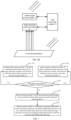
- the mapping parameter between reference spectrum and ambient light spectrum is calibrated as shown in FIG. 2A .
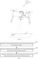
- the spectral reflectivity of the to-be-measured object is calculated based on the calibrated mapping parameter, the to-be-measured object is below the spectral reflectivity measurement system, and is an object with spectral reflectivity unknown, and the spectral reflectivity thereof needs to be calculated, as shown in FIG. 2B .
- the ambient light spectrum in this process is referred to as calibrated ambient light spectrum
- the reference spectrum in this process is referred to as calibrated reference spectrum
- the target spectrum in this process is referred to as calibrated target spectrum.
- the ambient light spectrum in this process is referred to as measured ambient light spectrum
- the reference spectrum in this process is referred to as measured reference spectrum
- the target spectrum in this process is referred to as measured target spectrum.
- the process of determining the mapping parameter may include steps 301 to 305, as shown in FIG. 3 .
- the ambient light sensing module 11 collects calibrated ambient light spectrum at a target calibration time, and sends the calibrated ambient light spectrum to the data processing module 13.
- the calibrated ambient light spectrum may be spectrum of the first ambient light, and the first ambient light may be ambient light sensed by the ambient light sensing module 11.
- the target spectrum collection module 12 collects calibrated target spectrum at the target calibration time, and sends the calibrated target spectrum to the data processing module 13.
- the calibrated target spectrum is spectrum reflected by the calibration object for the second ambient light, and the second ambient light is ambient light sensed by the target spectrum collection module 12.
- the calibration object is an object with known spectral reflectivity, for example, a whiteboard or a standard reflectivity board or the like.
- the type of the calibration object is not limited herein. In subsequent embodiments, descriptions are made with a whiteboard as an example.
- the collection range of the target spectrum collection module 12 and the sensing range of the ambient light sensing module 11 are consistent in ambient light illuminance, and the upper and lower light environments thereof are not blocked by shades.
- the whiteboard is placed within the collection range of the target spectrum collection module 12, while the whiteboard can fully cover the collection range of the target spectrum collection module 12, as shown in FIG. 2A .
- the target spectrum collection module 12 and the ambient light sensing module 11 perform spectrum collection simultaneously, namely, collect the spectrum at the same time (the time is referred to as target calibration time).
- the spectrum collected by the ambient light sensing module 11 is the calibrated ambient light spectrum
- the spectrum collected by the target spectrum collection module 12 is the calibrated target spectrum.
- the target calibration time may be multiple times, for example, a time T1, and a time T2 and the like. Therefore, the ambient light sensing module 11 may collect the calibrated ambient light spectrum at the time T1, and the target spectrum collection module 12 may collect the calibrated target spectrum at the time T1; the ambient light sensing module 11 may collect the calibrated ambient light spectrum at the time T2, and the target spectrum collection module 12 may collect the calibrated target spectrum at the time T2, and so on.
- the data processing module 13 determines whether to adjust an exposure time. If yes, the exposure time is adjusted, the data processing module 13 notifies the ambient light sensing module 11 to collect the calibrated ambient light spectrum based on the adjusted exposure time, that is, repeat the step 301, and also notifies the target spectrum collection module 12 to collect the calibrated target spectrum based on the adjusted exposure time, that is, repeat the step 302. If not, step 304 can be performed.
- the data processing module 13 may determine a maximum value of all the calibrated ambient light spectrum and all the calibrated target spectra, and take the maximum value as a maximum spectrum value.
- a first exposure time is adjusted to a second exposure time greater than the first exposure time, that is, the value of the first exposure time is increased, where the first exposure time is an exposure time currently used by the ambient light sensing module 11 and the target spectrum collection module 12. Then, the data processing module 13 sends the second exposure time to the ambient light sensing module 11, and the ambient light sensing module 11 collects calibrated ambient light spectrum based on the second exposure time, that is, the ambient light sensing module 11 collects the ambient light spectrum under the second exposure time by repeating the step 301.
- the data processing module 13 sends the second exposure time to the target spectrum collection module 12, and the target spectrum collection module 12 collects calibrated target spectrum based on the second exposure time, that is, the target spectrum collection module 12 collects the calibrated target spectrum under the second exposure time by repeating the step 302.
- the first exposure time is adjusted to a third exposure time less than the first exposure time, namely, the value of the first exposure time is decreased. Then, the data processing module 13 sends the third exposure time to the ambient light sensing module 11, and the ambient light sensing module 11 collects calibrated ambient light spectrum based on the third exposure time by repeating the step 301. Further, the data processing module 13 sends the third exposure time to the target spectrum collection module 12, and the target spectrum collection module 12 collects calibrated target spectrum based on the third exposure time by repeating the step 302.
- the maximum spectrum value is not less than the preset minimum spectrum value and not greater than the preset maximum spectrum value, that is, the maximum spectrum value is between the preset minimum spectrum value and the preset maximum spectrum value, it indicates that the first exposure time currently used by the ambient light sensing module 11 and the target spectrum collection module 12 is reasonable and does not need to be adjusted.
- the data processing module 13 determines not to adjust the exposure time and can perform the step 304.
- the data processing module 13 may analyze whether the exposure time is proper, that is, whether to adjust the exposure time. If yes, the exposure time is adjusted, the ambient light sensing module 11 and the target spectrum collection module 12 are notified to adjust the exposure time.
- the data processing module 13 performs spectrum preprocessings such as data filtering, dark noise reduction and the like on the calibrated ambient light spectrum and the calibrated target spectra, which is not limited herein.
- the data processing module 13 determines a mapping relationship between reference spectrum and ambient light spectrum based on the calibrated ambient light spectrum and the calibrated target spectra, and stores the mapping relationship between reference spectrum and ambient light spectrum.
- the implementation process of the step 305 may include step 3051 to step 3053.
- a calibrated ambient light spectrum and a calibrated target spectrum at the same target wavelengths are determined.
- the calibrated ambient light spectrum may be calibrated ambient light spectrum of multiple wavelengths
- the calibrated target spectrum may be calibrated target spectrum of multiple wavelengths.
- the ambient light sensing module 11 is configured to collect calibrated ambient light spectrum at each wavelength in a first wavelength set
- the target spectrum collection module 12 is configured to collect calibrated target spectrum at each wavelength in a second wavelength set, where the first wavelength set is a subset of the second wavelength set, for example, the first wavelength set includes a wavelength a1, a wavelength a3 and a wavelength a5, and the second wavelength set includes a wavelength a1, a wavelength a2, a wavelength a3, a wavelength a4, and a wavelength a5.
- the number of the wavelengths in the first wavelength set may be far greater than 3, for example, the wavelengths may be dozens of wavelengths, and the number of the wavelengths in the second wavelength set may be far greater than 5, for example, the wavelengths may be several hundred wavelengths, which is not limited herein.
- the number of the wavelengths may also be referred to as the number of spectral channels, for example, the number of spectral channels may be 3 or 5 or the like.
- the data processing module 13 may obtain multiple calibrated ambient light spectrum and multiple calibrated target spectrum at the same target calibration time.
- the data processing module 13 may obtain a calibrated ambient light spectrum b1 of the wavelength a1, a calibrated ambient light spectrum b3 of the wavelength a3, a calibrated ambient light spectrum b5 of the wavelength a5, a calibrated target spectrum c1 of the wavelength a1, a calibrated target spectrum c2 of the wavelength a2, a calibrated target spectrum c3 of the wavelength a3, a calibrated target spectrum c4 of the wavelength a4, and a calibrated target spectrum c5 of the wavelength a5.
- the data processing module 13 may take each wavelength in the second wavelength set (e.g., the wavelength a1, the wavelength a2, the wavelength a3, the wavelength a4, and the wavelength a5) as a target wavelength.
- the calibrated ambient light spectrum b1 and the calibrated target spectrum c1 are a calibrated ambient light spectrum and a calibrated target spectrum at the same target wavelength a1.
- the calibrated ambient light spectrum b3 and the calibrated target spectrum c3 are a calibrated ambient light spectrum and a calibrated target spectrum at the same target wavelength a3.
- the calibrated ambient light spectrum b5 and the calibrated target spectrum c5 are a calibrated ambient light spectrum and a calibrated target spectrum at the same target wavelength a5.
- a calibrated ambient light spectrum corresponding to the wavelength a2 may be calculated, and denoted as the calibrated ambient light spectrum b2, where the calculation manner is not limited herein.
- the calibrated ambient light spectrum b2 may be calculated in the following manner: a first matching wavelength and a second matching wavelength are selected from the first wavelength set, where the first matching wavelength is a wavelength closest to the wavelength a2 and less than the wavelength a2 in the first wavelength set, for example, the wavelength a1; the second matching wavelength is a wavelength closest to the wavelength a2 and greater than the wavelength a2 in the first wavelength set, for example, the wavelength a3.
- the calibrated ambient light spectrum b2 of the wavelength b2 is calculated, for example, interpolation operation, mean operation and weighted operation (a weight may be configured randomly) and the like may be performed on the calibrated ambient light spectrum b 1 and calibrated ambient light spectrum b3 to obtain the calibrated ambient light spectrum b2.
- This calculation manner is not limited herein as long as the calibrated ambient light spectrum b2 can be obtained.
- the calibrated ambient light spectrum b2 and the calibrated target spectrum c2 are a calibrated ambient light spectrum and a calibrated target spectrum to the same target wavelength a2.
- the calibrated ambient light spectrum b4 corresponding to the wavelength a4 may be calculated. For example, based on the calibrated ambient light spectrum b3 of the wavelength a3 and the calibrated ambient light spectrum b5 of the wavelength a5, the calibrated ambient light spectrum b4 of the wavelength a4 may be calculated, which is not limited herein.
- the calibrated ambient light spectrum b4 and the calibrated target spectrum c4 are a calibrated ambient light spectrum and a calibrated target spectrum at the same target wavelength a4.
- the calibrated ambient light spectrum and the calibrated target spectrum corresponding to each target wavelength can be obtained.
- subsequent steps may be performed based on the calibrated ambient light spectrum and the calibrated target spectrum at the target wavelength to obtain a mapping parameter at the target wavelength, and store the mapping relationship, namely, store the mapping parameter corresponding to each target wavelength.
- subsequent steps are performed based on the calibrated ambient light spectrum and the calibrated target spectrum at the target wavelength.
- a calibrated reference spectrum at the target wavelength is determined, where the calibrated reference spectrum may be a spectrum of the second ambient light, and the second ambient light is ambient light sensed by the target spectrum collection module 12.
- the calibrated target spectrum is obtained after the calibrated reference spectrum is reflected by the calibration object. Therefore, when the calibrated target spectrum and the spectral reflectivity of the calibration object are known, the calibrated reference spectrum can be determined, for example, by dividing the calibrated target spectrum by the spectral reflectivity.
- a mapping parameter at the target wavelength is determined, and then the mapping parameter at the target wavelength is stored, where the mapping parameter is used to represent a mapping relationship between reference spectrum and ambient light spectrum.
- the function relationship f will be more complex.
- y represents a reference spectrum
- x represents an ambient light spectrum
- k represents a mapping parameter between reference spectrum and ambient light spectrum.
- y represents a reference spectrum which is a known value, namely, the calibrated reference spectrum at the target wavelength
- x represents an ambient light spectrum which is also a known value, namely, the calibrated ambient light spectrum at the target wavelength
- the ambient light sensing module 11 may also collect position data, and send the position data to the data processing module 13.
- the data processing module 13 may determine an angle parameter based on the position data, and based on the angle parameter, the calibrated reference spectrum and the calibrated ambient light spectrum, determine the mapping parameter, where the mapping parameter represents a mapping relationship among reference spectrum, ambient light spectrum and angle parameter.
- the angle parameter may be a pose angle corresponding to the pose information, for example, the pose information is the pose angle of the ambient light sensing module 11, and thus the pose angle of the ambient light sensing module 11 can be directly determined; and/or, if the position data is longitude and latitude information of the ambient light sensing module 11, the angle parameter may be a zenith angle corresponding to the longitude and latitude information, for example, the zenith angle of the sun may be determined based on the longitude and latitude information of the ambient light sensing module 11, which is not limited herein.
- the angle parameter may also include a zenith angle of the calibration object, for example, the zenith angle of the calibration object is pre-configured, for example, for vertically-down collection and horizontal collection, the zenith angle of the calibration object may be configured as 0 and 90 degrees.
- x represents an ambient light spectrum
- y represents a reference spectrum
- k represents a mapping parameter among angle parameter, reference spectrum and ambient light spectrum.
- p represents an angle parameter
- y f(x,k,p1,p2,p3)
- y represents a calibrated reference spectrum corresponding to a target wavelength
- x represents a calibrated ambient light spectrum corresponding to a target wavelength
- the function relationship f is already configured
- p1 represents a pose angle of the ambient light sensing module 11
- p2 represents a zenith angle of the sun
- p3 represents a zenith angle of a calibration object.
- mapping relationship model may be obtained, where the mapping relationship model may map the ambient light spectrum to a reference spectrum, so as to obtain the mapping parameter k.
- the input-output relationship may be represented by f , where f is related to x, p1, p2, p3, z, k and the like, x(IE) represents an ambient light spectrum, p1 represents a pose angle of the ambient light sensing module 11, p2 represents a zenith angle of the sun, p3 represents a zenith angle of a calibration object, z represents a spectral reflectivity of a whiteboard, k represents a mapping parameter, namely, a value to be determined in the determination process, and y(Iref) represents a reference spectrum.
- mapping relationship model y f(x,p1,p2,p3,z,k) is only an example, and in practical applications, at least one parameter of p1, p2, p3, or z may also be removed.
- the mapping relationship model herein is not limited.
- the reference spectrum may be obtained by performing direct mapping on the ambient light spectrum of the ambient light sensing module 11 and the mapping parameter without using the whiteboard again.
- the calculation process of the spectral reflectivity of the to-be-measured object may include step 401 to 405, as shown in FIG. 4 .
- the ambient light sensing module 11 collects measured ambient light spectrum at a target measurement time, and sends the measured ambient light spectrum to the data processing module 13, where the measured ambient light spectrum may be spectrum of the first ambient light, and the first ambient light is ambient light sensed by the ambient light sensing module 11.
- the target spectrum collection module 12 collects measured target spectrum at the target measurement time, and sends the measured target spectrum to the data processing module 13, where the measured target spectrum is spectrum reflected by the to-be-measured object for the second ambient light, and the second ambient light is ambient light sensed by the target spectrum collection module 12.
- the to-be-measured object is an object with its spectral reflectivity to be calculated, which is not limited herein.
- the target measurement time may be any time, for example, a time t1 ; the ambient light sensing module 11 may collect a measured ambient light spectrum at the time t1, and the target spectrum collection module 12 may collect a measured target spectrum at the time t1.
- the collection range of the target spectrum collection module 12 and the sensing range of the ambient light sensing module 11 are consistent in ambient light illuminance, and the upper and lower light environments thereof are not blocked by shades; the to-be-measured object is placed within the collection range of the target spectrum collection module 12.
- the data processing module 13 determines whether to adjust an exposure time. If yes, the exposure time is adjusted, the data processing module 13 notifies the ambient light sensing module 11 to collect the measured ambient light spectrum based on the adjusted exposure time, that is, repeat the step 301, and also notifies the target spectrum collection module 12 to collect the measured target spectrum based on the adjusted exposure time, that is, repeat the step 302. If not, the exposure time is not adjusted, step 404 can be performed.
- the data processing module 13 may determine a maximum spectrum value, i.e., a maximum spectrum value in all the measured ambient light spectrum values and all the measured target spectrum values. If the maximum spectrum value is less than a preset minimum spectrum value, the data processing module 13 adjusts a first exposure time to a second exposure time, where the second exposure time is greater than the first exposure time, and the first exposure time is an exposure time currently used by the ambient light sensing module 11 and the target spectrum collection module 12.
- the data processing module 13 sends the second exposure time to the ambient light sensing module 11, such that the ambient light sensing module 11 collects measured ambient light spectrum based on the second exposure time, and sends the second exposure time to the target spectrum collection module 12, such that the target spectrum collection module 12 collects measured target spectrum based on the second exposure time.
- the maximum spectrum value is greater than a preset maximum spectrum value
- the first exposure time is adjusted to a third exposure time less than the first exposure time
- the third exposure time is sent to the ambient light sensing module 11, such that the ambient light sensing module 11 collects measured ambient light spectrum based on the third exposure time
- the third exposure time is further sent to the target spectrum collection module 12, such that the target spectrum collection module 12 collects measured target spectrum based on the third exposure time.
- the maximum spectrum value is not less than the preset minimum spectrum value and not greater than the preset maximum spectrum value, it indicates that the first exposure time currently used by the ambient light sensing module 11 and the target spectrum collection module 12 is reasonable, and the step 404 can be performed.
- the data processing module 13 performs spectrum preprocessing such as data filtering and dark noise reduction and the like on the measured ambient light spectrum and the measured target spectrum, which is not limited herein.
- the data processing module 13 determines the spectral reflectivity of the to-be-measured object based on the measured ambient light spectrum, the measured target spectrum, and the mapping relationship between reference spectrum and ambient light spectrum.
- the implementation process of the step 405 may include step 4051 to step 4053.
- the measured ambient light spectrum and the measured target spectrum at the same target wavelengths are determined.
- the ambient light sensing module 11 is configured to collect measured ambient light spectrum at each wavelength in the first wavelength set
- the target spectrum collection module 12 is configured to collect the measured target spectrum at each wavelength in the second wavelength set, where the first wavelength set is a subset of the second wavelength set.
- the data processing module 13 takes each wavelength in the second wavelength set as the target wavelength, and for each target wavelength: the measured target spectrum at the target wavelength is obtained from the target spectrum collection module 12; whether the target wavelength is existed in the first wavelength set is determined; if the target wavelength is existed in the first wavelength set, the measured ambient light spectrum at the target wavelength is obtained from the ambient light sensing module 11; if the target wavelength is not existed in the first wavelength set, based on the measured ambient light spectrum at at least two wavelengths collected by the ambient light sensing module 11, the measured ambient light spectrum at the target wavelength is determined.
- a first matching wavelength and a second matching wavelength are selected from the first wavelength set, where the first matching wavelength is a wavelength closest to the target wavelength and less than the target wavelength in the first wavelength set, and the second matching wavelength is a wavelength closest to the target wavelength and greater than the target wavelength in the first wavelength set. Based on the measured ambient light spectrum at the first matching wavelength and the measured ambient light wavelength at the second matching wavelength, the measured ambient light spectrum at the target wavelength is determined.
- the implementation process of the step 4051 is similar to the implementation process of the step 3051 and will not be repeated herein.
- the measured ambient light spectrum and the measured target spectrum corresponding to each target wavelength may be obtained.
- subsequent steps are performed to obtain the spectral reflectivity at the target wavelength.
- subsequent steps are performed.
- a measured reference spectrum is determined, where the measured reference spectrum may be a spectrum of the second ambient light.
- mapping parameter k is a known value
- x represents a measured ambient light spectrum corresponding to a target wavelength
- the ambient light sensing module 11 may also collect position data and send the position data to the data processing module 13.
- the data processing module 13 may determine an angle parameter based on the position data, and based on the measured ambient light spectrum, the angle parameter and the mapping parameter, determine the measured reference spectrum, where the mapping parameter represents a mapping relationship among reference spectrum, ambient light spectrum and angle parameter.
- the angle parameter may be a pose angle corresponding to the pose information, for example, the pose information is the pose angle of the ambient light sensing module 11, and thus the pose angle of the ambient light sensing module 11 can be directly determined; and/or, if the position data is longitude and latitude information of the ambient light sensing module 11, the angle parameter may be a zenith angle corresponding to the longitude and latitude information, for example, the zenith angle of the sun may be determined based on the longitude and latitude information of the ambient light sensing module 11, which is not limited herein.
- the angle parameter may also include a zenith angle of the to-be-measured object, for example, the zenith angle of the to-be-measured object is pre-configured, for example, for vertically-down collection and horizontal collection, the zenith angle of the to-be-measured object may be configured as 0 and 90 degrees.
- p represents an angle parameter
- y represents a measured reference spectrum corresponding to a target wavelength
- x represents a measured ambient light spectrum corresponding to a target wavelength
- p1 represents a pose angle of the ambient light sensing module 11
- p2 represents a zenith angle of the sun
- p3 represents a zenith angle of a to-be-measured object
- k represents a mapping parameter.
- the pose angle p1 of the ambient light sensing module 11, the zenith angle p2 of the sun, and the zenith angle p3 of the to-be-measured object are used for correcting the inaccurate measured reference spectrum calculated in the cases of change of the pose of the ambient light sensing module 11, inconsistent pose of the to-be-measured object, or excessive change of the zenith angle of the sun or the like, so as to obtain a more accurate measured reference spectrum.
- the measured reference spectrum at the target wavelength is determined.
- the spectral reflectivity of the to-be-measured object is determined.
- substance parameter inversion may be further performed, namely, the data processing module 13 may introduce the spectral reflectivity into a corresponding inversion model based on an application scenario to perform inversion on the spectral reflectivity and obtain a parameter of the to-be-measured object relating to the spectral reflectivity.
- the ambient light sensing module 11 may include at least a light homogenization path and a multispectral sensor, where the light homogenization path is coupled to the multispectral sensor; the ambient light goes through the light homogenization path for light homogenization processing, and then is transmitted to the multispectral sensor, and the multispectral sensor collects ambient light spectrum of multiple wavelengths.
- the light homogenization path can transmit and then homogenize the rays with different incidence angles, such that the transmitted light is diffusely scattered at multiple angles, which is unrelated to the incidence angle.
- the homogenized light is transmitted to the multispectral sensor.
- the multispectral sensor can measure the spectral intensities of multiple wave bands and receive the homogenized light.
- the light current output of the multispectral sensor conforms to cosine response.
- the multispectral sensor may be a multichannel photodiode, or a multichannel spectral sensor or a single-point optical fiber spectrometer.
- the ambient light sensing module 11 includes at least a light homogenization path, an optical fiber and an optical fiber spectrometer. One end of the optical fiber is connected with the optical fiber spectrometer, and the other end of the optical fiber is connected with the light homogenization path.
- the ambient light goes through the light homogenization path for light homogenization processing, and then is transmitted through the optical fiber to the optical fiber spectrometer, and the optical fiber spectrometer collects ambient light spectrum of multiple wavelengths.
- the multispectral sensor is replaced with the optical fiber spectrometer and the light homogenization path is connected with the optical fiber spectrometer via the optical fiber, other structures are similar to above manners. No redundant descriptions are made herein.
- the number of wavelengths of the ambient light spectrum collected by the optical fiber spectrometer is greater than the number of the wavelengths of the ambient light spectrum collected by the multispectral sensor.
- the optical fiber spectrometer can collect the ambient light spectrum of several hundred wavelengths whereas the multispectral sensor can collect the ambient light spectrum of dozens of wavelengths.
- the ambient light sensing module 11 may further include a pose sensor (e.g., gyro sensor) and/or a position sensor (e.g., GPS).
- the pose sensor is used to collect pose information (e.g., a pose angle of the ambient light sensing module 11 relative to horizontal plane) and the position sensor is used to collect longitude and latitude information.
- the target spectrum collection module 12 may include a lens and a hyperspectral imager.
- the lens can perform imaging or light reception on a target region, and may be connected with the hyperspectral imager directly or by an optical fiber, and also may be an imaging lens or a collimating lens or the like.
- the hyperspectral imager can obtain spectral information of different wave bands reflected or irradiated by the target region for which the lens performs imaging or light reception, that is, obtain target spectra.
- the hyperspectral imager may be a single-point optical fiber spectrometer, a push-broom imaging spectrometer or a staring imaging spectrometer.
- the target spectrum collection module 12 includes at least a lens and an optical fiber spectrometer (e.g., single-point optical fiber spectrometer).
- the lens is connected with the optical fiber spectrometer (directly connected or connected by an optical fiber).
- the lens can collect light formed after ambient light is reflected by the to-be-measured object and transmit the light to the optical fiber spectrometer, and the optical fiber spectrometer collects the target spectrum of multiple wavelengths.
- the target spectrum collection module 12 includes at least a lens and an imaging spectrometer (e.g., a push-broom imaging spectrometer or a staring imaging spectrometer).
- the lens is connected with the imaging spectrometer; this lens can collect light formed after ambient light is reflected by the to-be-measured object and transmit the light to the imaging spectrometer, and the imaging spectrometer collects the target spectrum of multiple wavelengths.
- 1 indicates the light homogenization path of the ambient light sensing module 11, which can transmit and homogenize the rays with different incidence angles; and hence the transmitted light is diffusely scattered at multiple angles, which is unrelated to the incidence angle.
- the homogenized light is transmitted to the multispectral sensor.
- 2 indicates the multispectral sensor of the ambient light sensing module 11, which can obtain the spectral intensities of multiple wavelengths and receive the homogenized light.
- the light current output of the multispectral sensor conforms to cosine response, and the multispectral sensor can collect the spectrum of the target region (i.e., ambient light spectrum).
- 3 indicates the pose sensor (e.g., gyro sensor) and the position sensor (e.g., GPS), which can obtain the longitude and latitude information and the pose angle and the like of the ambient light sensing module 11.
- 4 indicates the lens of the target spectrum collection module 12, which has light reception function.
- 5 indicates the optical fiber spectrometer (e.g., single-point optical fiber spectrometer) of the target spectrum collection module 12, which is directly connected to the lens to collect the spectrum (i.e., target spectrum) of the target region.
- 6 indicates an industrial control board, namely, the data processing module 13, which controls the multispectral sensor, the pose sensor, the position sensor and the optical fiber spectrometer and the like, and has the capabilities of data reception, data processing, uploading and storage and the like.
- the light homogenization path 1 is coupled to the multispectral sensor 2, that is, mounted vertically upward to exactly face toward the zenith, and the pose sensor and the position sensor 3 are consistent in pose with the light homogenization path 1 and the multispectral sensor 2.
- the lens 4 and the optical fiber spectrometer 5 are mounted vertically downward to collect the spectrum of the region below.
- the measured object may be the whiteboard or the to-be-measured object in the above embodiments. As shown in FIG. 5A , it is the case of the to-be-measured object and as shown in FIG. 5B , it is the case of the whiteboard.
- the solar light can irradiate on the light homogenization path 1 and the measured object at the same time with the same solar irradiance.
- the solar light goes through the light homogenization path 1 and then is received by the multispectral sensor 2, so as to obtain the ambient light spectra.
- a light signal of the measured object is collected and received by the lens 4 and then split by the optical fiber spectrometer 5, so as to obtain the target spectra.
- the industrial control board 6 receives data from the multispectral sensor 2, the optical fiber spectrometer 5, the pose sensor and the position sensor 3, and performs exposure control on the multispectral sensor 2 and the optical fiber spectrometer 5. After the exposure is completed, the data is preprocessed. After the preprocessing is completed, the ambient light spectrum is mapped to the reference spectrum based on the pre-calibrated mapping parameter, and then the spectral reflectivity is calculated based on the reference spectrum and the target spectrum.
- 7 is the optical fiber
- 8 is the single-point optical fiber spectrometer.
- This scenario differs from the application scenario 1 in that: the multispectral sensor may also be replaced with the single-point optical fiber spectrometer which has a larger number of collection channels (the number of the channels of the ambient light spectrum is larger).
- One end of the optical fiber 7 is connected with the optical fiber spectrometer 8 and the other end of the optical fiber is coupled to the light homogenization path 1 to collect ambient light.
- the ambient light goes through the light homogenization path 1 and the optical fiber 7 and then into the optical fiber spectrometer 8 for splitting, and finally the optical fiber spectrometer 8 obtains the ambient light spectrum.
- 9 is the imaging spectrometer.
- This scenario differs from the application scenario 1 in that: the single-point optical fiber spectrometer (hyperspectral imager) may also be replaced with the imaging spectrometer, and the imaging spectrometer 9 can obtain a hyperspectral image of the entire imaging region in combination with the lens 4.
- the lens 4 and the imaging spectrometer 9 are still mounted downward to collect a hyperspectral image of an imaging region below.
- the imaging spectrometer 9 may be a staring snapshot type imaging spectrometer and can obtain a hyperspectral image by reconstruction or rearrangement after one exposure.
- the imaging spectrometer 9 may be a staring adjustable filter type or a time-domain Fourier type imaging spectrometer, which can obtain a hyperspectral image by multiple exposures of time domain.
- the imaging spectrometer 9 may be a push-broom type imaging spectrometer which is internally or externally provided with a push-broom device to obtain a hyperspectral image by multiple exposures of space-domain push-broom.
- the processes of the calibration and the calculation of the spectral reflectivity are similar.
- a calibration flow when the mapping parameter is calculated, it is required to additionally extract the spectral data of the whiteboard region in the hyperspectral image.
- the calculation flow of the spectral reflectivity one hyperspectral reflectivity cube is obtained instead of one spectral reflectivity curve.
- the ambient light sensing module 11 or the entire spectral reflectivity measurement system may be tilted to an angle for operation.
- FIG. 5E shows that for the application scenario 3, the entire spectral reflectivity measurement system is tilted to an angle for operation or, only the ambient light sensing module 11 is tilted to an angle for operation.
- the entire spectral reflectivity measurement system is tilted to an angle for operation, or the ambient light sensing module 11 is tilted to an angle for operation. No redundant descriptions are made herein.
- the ambient light spectrum may be corrected based on a pose angle obtained from the pose sensor (e.g., gyro sensor), namely, the mapping parameter in the above embodiments may be related to the pose angle of the ambient light sensing module 11, and thus can be applied to the angle change resulting from change of external environment, for example, the angle change, resulting from waves, of the spectral reflectivity measurement system mounted on pontoon or ship.
- the pose sensor e.g., gyro sensor
- the mapping parameter in the above embodiments may be related to the pose angle of the ambient light sensing module 11, and thus can be applied to the angle change resulting from change of external environment, for example, the angle change, resulting from waves, of the spectral reflectivity measurement system mounted on pontoon or ship.
- the target spectrum collection module 12 may be mounted horizontally or at another angle for operation to collect the target spectrum vertical to the ground, perform correction on the reference spectrum based on the angle of the to-be-measured object relative to the zenith, and obtain the spectral reflectivity under the current scenario, that is, the above mapping parameter may be related to the zenith angle of the to-be-measured object and the zenith angle of the sun.
- FIG. 5F shows that, for the application scenario 3, the target spectrum collection module 12 is mounted horizontally or at another angle for operation, or for the application scenario 1, the target spectrum collection module 12 may also be mounted horizontally or at another angle for operation.
- FIG. 6A it shows a practical scenario application based on the application scenario 2, the spectral reflectivity measurement system is applied to the application scenario of fixed-point in-situ water quality monitoring.
- the solar light irradiates on the light homogenization material and the water body region at the same time, with the same solar irradiance.
- the solar light goes through the light homogenization path and then is received by the optical fiber spectrometer as ambient light spectra.
- the ambient light spectrum is mapped by the ambient light mapping relationship model (i.e., mapping parameter), and then the reference spectrum in the calculation of the spectral reflectivity is obtained.
- the ambient light mapping relationship model i.e., mapping parameter
- the uplink water-leaving radiation light signal of the water body is received by the lens and then received by the optical fiber spectrometer as the target spectrum in the calculation of the spectral reflectivity.
- the industrial control board calculates the spectral reflectivity of the water-leaving radiation and then inputs the spectral reflectivity into an introduced water body parameter inversion model to perform water quality inversion on the spectral reflectivity, so as to obtain a water quality parameter value of the current quality.
- the water quality inversion process is not limited herein, and all-weather in-situ online water quality monitoring can be achieved.
- the indexes and ranges of the water quality parameter are as follows: chlorophyll a: 0 to 500 ug/L, total nitrogen: 0 to 20mg/L, total phosphorus: 0 to 2mg/L, transparency: 0 to 5m, potassium permanganate index: 0 to 20mg/L, turbidity: 0 to 1000NTU, ammonia nitrogen: 0 to 10 mg/L, suspended matter concentration: 0 to 300 mg/L, CDOM absorption coefficient: 0 to 30 m -1 , extinction coefficient C550: 0 to 100 m -1 and the like.
- the spectral reflectivity measurement system is applied to the application scenario of the hyperspectral remote sensing of an unmanned aerial vehicle.
- the unmanned aerial vehicle is under the solar light
- the solar light irradiates on the light homogenization material and the target region at the same time, with the same solar irradiance.
- the solar light goes through the light homogenization path and then is received by the optical fiber spectrometer as ambient light spectra; after the ambient light spectrum is mapped by the ambient light mapping relationship model (i.e., mapping parameter), the reference spectrum in the calculation of the spectral reflectivity can be obtained.
- the ambient light mapping relationship model i.e., mapping parameter
- the light signal diffusely reflected by the object is received by the lens and then received by the hyperspectral camera (i.e., imaging spectrometer) as the target spectrum in the calculation of the spectral reflectivity. Due to use of the hyperspectral camera, the obtained target spectrum is linear-arrayed target spectrum or area-arrayed target spectrum.
- the industrial control board calculates a linear-arrayed spectral reflectivity or area-arrayed spectral reflectivity based on the entire linear-arrayed target spectrum or area-arrayed target spectrum in combination with the obtained reference spectra.
- the spectral reflectivity measurement system is applied to the hyperspectral remote sensing of the unmanned aerial vehicle, and can obtain the reference spectrum stably in real time and thus the finally-obtained spectral reflectivity cube is free from the influence of the solar irradiance change.
- the calibration flow of the mapping relationship is similar to the above embodiments.
- a whiteboard is placed within a field of view of the hyperspectral camera, and the hyperspectral camera collects one frame of a hyperspectral image containing the whiteboard, and the ambient light sensing module 11 collects multispectral data of one frame of a current environment image.
- a model of an ambient light mapping relationship can be established to realize calibration of the mapping parameter.
- FIG. 6C it shows a practical scenario application based on the application scenario 4, the spectral reflectivity measurement system is applied to the application scenario of hyperspectral remote sensing of an unmanned aerial vehicle.
- FIG. 6C is a special state of FIG. 6B .
- the pose sensor e.g., gyro sensor
- the pose sensor may sense a pose of the unmanned aerial vehicle and obtain a pose angle, and then add the information of the pose angle into the model of the ambient light mapping relationship based on the obtained pose angle, helping accurately obtain the reference spectrum and eliminating the error of the calculation of the spectral reflectivity resulting from the tilt.
- a mapping parameter between reference spectrum and ambient light spectrum may be pre-determined, and thus the spectral reflectivity of the to-be-measured object can be accurately calculated, so as to realize fast, real-time, efficient and accurate acquisition of the spectral reflectivity of the to-be-measured object.
- the spectral reflectivity of the to-be-measured object can be obtained continuously in-situ and in real time in the wild, thus improving the convenience and the real-timeness of obtaining the spectral reflectivity of the ground object (i.e., the to-be-measured object) in the wild.
- the spectral reflectivities under different weathers at different solar altitude angles can be obtained by simply using a calibration object (e.g., standard whiteboard) to perform one calibration (i.e., to determine the mapping parameter) without repeatedly collecting the data of the calibration object, and further, by calibrating the solar altitude angle and/or pose angle or the like, the calculation accuracy of the spectral reflectivities in multiple use cases can be improved. Therefore, the reference spectrum of the to-be-measured object under solar irradiation can be obtained efficiently and conveniently based on the ambient light sensing module and the calibrated ambient light mapping relationship (i.e., mapping parameter).
- a calibration object e.g., standard whiteboard
- the ambient light sensing module includes a light homogenization path and a spectral sensor and has the characteristics of cosine response.
- the light current output of the spectral sensor conforms to the cosine response, namely, the light current generated at different incidence angles is equal to a product of a light current at the time of vertical incidence of light and a cosine of the incidence angle, eliminating the phenomenon in which reception cannot be performed or weakened due to large angle.
- the solar irradiation spectrum of the target region at different times at different solar altitude angles can be obtained.
- the calculation of the spectral reflectivity can be performed.
- the pose angle can be obtained to perform angle correction. Therefore, multiple mounting environments can be handled.
- an embodiment of the present disclosure provides a spectral reflectivity measurement method, which is applied to a spectral reflectivity measurement system.
- FIG. 7 it is a flowchart illustrating a spectral reflectivity measurement method. The method includes step 701 to step 703.
- a measured ambient light spectrum and a measured target spectrum at the same target wavelengths are determined, where a collection time of the measured ambient light spectrum is same as a collection time of the measured target spectrum; the measured ambient light spectrum is a spectrum of the first ambient light and the measured target spectrum is a spectrum reflected by the to-be-measured object for the second ambient light.
- the measured ambient light spectrum includes measured ambient light spectrum at each wavelength in the first wavelength set
- the measured target spectrum include measured target spectrum at each wavelength in the second wavelength set, where the first wavelength set is a subnet of the second wavelength set.
- Determining the measured ambient light spectrum and the measured target spectrum at the same target wavelengths includes but not limited to: taking each wavelength in the second wavelength set as the target wavelength, and for each target wavelength: obtaining the measured target spectrum at the target wavelength; and determining whether the target wavelength is existed in the first wavelength set; if yes, directly obtaining the measured ambient light spectrum at the target wavelength; if not, determining the measured ambient light spectrum at the target wavelength based on the measured ambient light spectrum at at least two wavelengths.
- a first matching wavelength and a second matching wavelength are selected from the first wavelength set, where the first matching wavelength is a wavelength in the first wavelength set closest to the target wavelength and smaller than the target wavelength, and the second matching wavelength is a wavelength in the first wavelength set closest to the target wavelength and larger than the target wavelength; based on the measured ambient light spectrum at the first matching wavelength and the measured ambient light spectrum at the second matching wavelength, the measured ambient light spectrum at the target wavelength is determined.
- a maximum spectrum value in the measured ambient light spectrum and the measured target spectrum may also be determined. If the maximum spectrum value is less than a preset minimum spectrum value, a first exposure time currently used is adjusted to a second exposure time, where the second exposure time is greater than the first exposure time; measured ambient light spectrum is collected based on the second exposure time, and measured target spectrum is collected based on the second exposure time.
- the first exposure time currently used is adjusted to a third exposure time, where the third exposure time is less than the first exposure time; measured ambient light spectrum is collected based on the third exposure time, and measured target spectrum is collected based on the third exposure time.
- a measured reference spectrum is determined based on the measured ambient light spectrum and a determined mapping parameter, where the measured reference spectrum is a spectrum of the second ambient light, and the mapping parameter represents a mapping relationship between reference spectrum and ambient light spectrum, and is determined and stored in the process of determining the mapping parameter.
- position data may also be collected, an angle parameter is determined based on the position data, and the measured reference spectrum is determined based on the measured ambient light spectrum, the angle parameter and the mapping parameter, where the mapping parameter represents a mapping relationship among reference spectrum, ambient light spectrum and angle parameter.
- the angle parameter is a pose angle corresponding to the pose information; and/or, if the position data is longitude and latitude information of the spectral reflectivity measurement system, the angle parameter is a zenith angle corresponding to the longitude and latitude information, for example, a zenith angle of the sun.
- a spectral reflectivity of the to-be-measured object is determined based on the measured target spectrum and the measured reference spectrum.
- the determining process of the mapping parameter may include but not limited to: determining a calibrated ambient light spectrum and a calibrated target spectrum at the same target wavelengths, where a collection time of the calibrated ambient light spectrum is same as a collection time of the calibrated target spectrum, the calibrated ambient light spectrum is a spectrum of the first ambient light, and the calibrated target spectrum is a spectrum reflected by a calibration object for the second ambient light. Then, a calibrated reference spectrum is determined based on the calibrated target spectrum and a configured spectral reflectivity of the calibration object, where the calibrated reference spectrum is a spectrum of the second ambient light. Then, the mapping parameter is determined based on the calibrated reference spectrum and the calibrated ambient light spectrum.
- the calibrated ambient light spectrum includes calibrated ambient light spectrum at each wavelength in the first wavelength set
- the calibrated target spectrum include the calibrated target spectrum at each wavelength in the second wavelength set, where the first wavelength set is a subnet of the second wavelength set.
- Determining the calibrated ambient light spectrum and the calibrated target spectrum at the same target wavelengths includes but not limited to: taking each wavelength in the second wavelength set as the target wavelength, and for each target wavelength: obtaining the calibrated target spectrum at the target wavelength; determining whether the target wavelength is existed in the first wavelength set; if yes, directly obtaining the calibrated ambient light spectrum at the target wavelength; if not, determining the calibrated ambient light spectrum at the target wavelength based on the calibrated ambient light spectrum at at least two wavelengths.
- a first matching wavelength and a second matching wavelength are selected from the first wavelength set, where the first matching wavelength is a wavelength closest to the target wavelength and smaller than the target wavelength in the first wavelength set, and the second matching wavelength is a wavelength closest to the target wavelength and larger than the target wavelength in the first wavelength set; based on the calibrated ambient light spectrum at the first matching wavelength and the calibrated ambient light spectrum at the second matching wavelength, the calibrated ambient light spectrum at the target wavelength is determined.
- a maximum spectrum value in the measured ambient light spectrum and the measured target spectrum may also be determined. If the maximum spectrum value is less than a preset minimum spectrum value, a first exposure time currently used is adjusted to a second exposure time, where the second exposure time is greater than the first exposure time; calibrated ambient light spectrum is collected based on the second exposure time, and calibrated target spectrum is collected based on the second exposure time.
- the first exposure time currently used is adjusted to a third exposure time, where the third exposure time is less than the first exposure time; calibrated ambient light spectrum is collected based on the third exposure time, and calibrated target spectrum is collected based on the third exposure time.
- position data may also be collected, an angle parameter is determined based on the position data, and the mapping parameter is determined based on the angle parameter, the calibrated reference spectrum, and the calibrated ambient light spectrum, where the mapping parameter represents a mapping relationship among reference spectrum, ambient light spectrum and angle parameter.
- the angle parameter is a pose angle corresponding to the pose information; and/or, if the position data is longitude and latitude information of the spectral reflectivity measurement system, the angle parameter is a zenith angle corresponding to the longitude and latitude information.
- the embodiments of the present disclosure may be provided as methods, systems, or computer program products. Therefore, the present disclosure may take the form of a pure hardware embodiment, a pure software embodiment, or an embodiment combining software and hardware. Furthermore, the embodiments of the present disclosure may take the form of a computer program product implemented on one or more computer available storage mediums (including but not limited to disk memories, CD-ROM, optical storage devices, etc.) containing computer available program codes.
- each flow and/or block in the flowcharts and/or block diagrams and combinations of flows and/or blocks in the flowcharts and/or block diagrams may be implemented by computer program instructions.
- These computer program instructions may be provided to a processor of a general-purpose computer, a special-purpose computer, an embedded processing machine, or other programmable data processing devices to produce a machine, such that the instructions executed by the processor of the computer or another programmable data processing device generate an apparatus for implementing functions specified in one or more flows in the flowchart and/or in one or more blocks in the block diagram.
- these computer program instructions may also be stored in a computer readable memory capable of directing a computer or another programmable data processing device to operate in a particular manner, such that the instructions stored in the computer readable memory generate a manufactured product including an instruction apparatus, where the instruction apparatus implements the functions specified in one or more flows in the flowchart and/or one or more blocks in the block diagram.
- These computer program instructions can also be loaded onto a computer or another programmable data processing device, such that a series of operation steps may be performed on the computer or other programmable device to generate computer-implemented processing, and thus instructions executed on the computer or other programmable device provide steps for implementing the function specified in one or more flows in the flowchart and/or one or more blocks in the block diagram.
Landscapes
- Physics & Mathematics (AREA)
- Spectroscopy & Molecular Physics (AREA)
- General Physics & Mathematics (AREA)
- Health & Medical Sciences (AREA)
- Life Sciences & Earth Sciences (AREA)
- Chemical & Material Sciences (AREA)
- Analytical Chemistry (AREA)
- Biochemistry (AREA)
- General Health & Medical Sciences (AREA)
- Immunology (AREA)
- Pathology (AREA)
- Engineering & Computer Science (AREA)
- Mathematical Physics (AREA)
- Theoretical Computer Science (AREA)
- Investigating Or Analysing Materials By Optical Means (AREA)
- Spectrometry And Color Measurement (AREA)
Abstract
Description
- The present disclosure relates to the field of optical processing technologies, and in particular to a method and system for measuring spectral reflectivity.
- Hyperspectral imaging refers to combining imaging technology with hyperspectral technology to obtain a two-dimensional geometric space and one-dimensional spectral information of a to-be-measured object as well as image data of a continuous narrow band with hyperspectral resolution.
- The hyperspectral technology is a technology which uses very narrow and continuous spectral channels (different from three channels of Red Green and Blue (RGB) and the like) to obtain spectral information of a to-be-measured object, in this technology, electromagnetic wave data (i.e., spectral information) of multiple spectral channels for the to-be-measured object can be collected, and then based on the features of these data, interested information of the to-be-measured object, such as molecular composition, relative content, material type and the like is obtained. In the remote sensing or substance measurement field, the spectral information of a to-be-measured object can be obtained based on a reflected light intensity of a to-be-measured object. However, due to inconsistency of the spectral components of the irradiation light sources, spectral lines obtained under different light sources are inconsistent. Therefore, the spectral information of the to-be-measured object cannot be obtained based only on the reflected light intensity of the to-be-measured object.
- In order to solve the problem that spectral lines obtained under different light sources are inconsistent due to inconsistency of the spectral components of the irradiation light sources, a spectral reflectivity may be taken as an evaluation feature of a to-be-measured object, that is, spectral information of the to-be-measured object is obtained in combination with the spectral reflectivity. The spectral reflectivity refers to a ratio of a luminous flux of reflected light of a to-be-measured object in a wave band to a luminous flux of incident light of this wave band.
- In conclusion, calculating a spectral reflectivity of a to-be-measured object is an important part for realizing hyperspectral imaging. However, till now, there is no effective implementation for accurately calculating the spectral reflectivity of the to-be-measured object.
- The present disclosure provides a spectral reflectivity measurement system. The spectral reflectivity measurement system includes an ambient light sensing module, a target spectrum collection module and a data processing module, where,
- the ambient light sensing module is configured to collect a measured ambient light spectrum at a target measurement time, and send the measured ambient light spectrum to the data processing module, where the measured ambient light spectrum is spectrum of first ambient light, and the first ambient light is ambient light sensed by the ambient light sensing module;
- the target spectrum collection module is configured to collect a measured target spectrum at the target measurement time, and send the measured target spectrum to the data processing module, where the measured target spectrum is spectrum reflected by a to-be-measured object for second ambient light, and the second ambient light is ambient light sensed by the target spectrum collection module; and
- the data processing module is configured to determine the measured ambient light spectrum and the measured target spectrum at the same target wavelengths, and determine a measured reference spectrum based on the measured ambient light spectrum and a determined mapping parameter, where the measured reference spectrum is a spectrum of the second ambient light; determine, based on the measured target spectrum and the measured reference spectrum, a spectral reflectivity of the to-be-measured object; where the mapping parameter refers to a mapping relationship between reference spectrum and ambient light spectrum.
- The present disclosure provides a spectral reflectivity measurement method. The method includes: determining a measured ambient light spectrum and a measured target spectrum at the same target wavelengths; where a collection time of the measured ambient light spectrum is same as a collection time of the measured target spectrum; the measured ambient light spectrum is a spectrum of first ambient light, and the measured target spectrum is a spectrum reflected by a to-be-measured object for second ambient light; based on the measured ambient light spectrum and a determined mapping parameter, determining a measured reference spectrum, where the measured reference spectrum is a spectrum of the second ambient light, and the mapping parameter represents a mapping relationship between reference spectrum and ambient light spectrum; based on the measured target spectrum and the measured reference spectrum, determining a spectral reflectivity of the to-be-measured object.
- From the above technical solutions, it can be seen that in the embodiments of the present disclosure, a mapping parameter between reference spectrum and ambient light spectrum may be pre-determined, and thus, based on a measured ambient light spectrum and a measured target spectrum at the same target wavelengths and the mapping parameter, a spectral reflectivity of a to-be-measured object can be determined. Hence, the spectral reflectivity of the to-be-measured object can be accurately calculated, so as to realize fast, real-time, efficient and accurate acquisition of the spectral reflectivity of the to-be-measured object. In this way, the spectral reflectivity of the to-be-measured object can be obtained continuously in real time in the wild, thus improving the convenience and the real-timeness of obtaining the spectral reflectivity of the ground object (i.e., the to-be-measured object) in the wild. During use, by simply using a calibration object (e.g., standard whiteboard) to perform one calibration (i.e., to determine the mapping parameter) without repeatedly collecting the data of the calibration object, the spectral reflectivities under different weathers at different solar altitude angles can be obtained, and further, by calibrating the solar altitude angle and/or pose angle or the like, the calculation accuracy of the spectral reflectivities in multiple use cases can be improved.
- To describe the technical solutions in the embodiments of the present disclosure more clearly, drawings required in descriptions of the embodiments of the present disclosure will be briefly introduced below. It is apparent that the drawings described below are merely some embodiments of the present disclosure and other drawings may be obtained by those of ordinary skill in the prior art based on these drawings in the embodiments of the present disclosure.
-
FIG. 1 is a structural schematic diagram illustrating a spectral reflectivity measurement system according to an embodiment of the present disclosure. -
FIG. 2A to FIG. 2B are schematic diagrams illustrating deployment of a spectral reflectivity measurement system according to an embodiment of the present disclosure. -
FIG. 3 is a schematic diagram illustrating a process of determining a mapping parameter according to an embodiment of the present disclosure. -
FIG. 4 is a schematic diagram illustrating a calculation process of a spectral reflectivity according to an embodiment of the present disclosure. -
FIG. 5A to FIG. 5F are structural schematic diagrams illustrating a spectral reflectivity measurement system according to an embodiment of the present disclosure. -
FIGS. 6A to 6C are schematic diagrams illustrating an actual scenario application according to an embodiment of the present disclosure. -
FIG. 7 is a flowchart illustrating a spectral reflectivity measurement method according to an embodiment of the present disclosure. - The terms used in the embodiments of the present disclosure are for the purpose of describing particle embodiments only, and are not intended to limit the present disclosure. The singular forms such as "a," 'said," and "the" used in the present disclosure and the appended claims are also intended to include multiple, unless the context clearly indicates otherwise. It is also to be understood that the term "and/or" as used herein refers to and includes any or all possible combinations of one or more associated listed items.
- It should be understood that although different information may be described using the terms such as first, second, third, etc. in the embodiments of the present disclosure, these information should not be limited to these terms. These terms are used only to distinguish one type of information from another. For example, without departing from the scope of the present disclosure, the first information may also be referred to as the second information and similarly, the second information may also be referred to as the first information. Depending on the context, the word "if' as used herein may be interpreted as "when" or "upon" or "in response to determining".
- In an embodiment of the present disclosure, there is provided a spectral reflectivity measurement system.
FIG. 1 is a structural schematic diagram illustrating the spectral reflectivity measurement system. As shown inFIG. 1 , the spectral reflectivity measurement system includes at least: an ambientlight sensing module 11, a targetspectrum collection module 12 and adata processing module 13. - The ambient
light sensing module 11 is configured to collect a measured ambient light spectrum at a target measurement time, and send the measured ambient light spectrum to thedata processing module 13, where the measured ambient light spectrum is spectrum of first ambient light, and the first ambient light is ambient light sensed by the ambientlight sensing module 11. For example, for all ambient light, the ambientlight sensing module 11 can sense a part of the ambient light, which is the first ambient light. The first ambient light may have different values at different times. The measured ambient light spectrum is spectrum corresponding to the first ambient light. - The target
spectrum collection module 12 is configured to collect a measured target spectrum at the target measurement time (the measurement time of the measured ambient light spectrum), and send the measured target spectrum to thedata processing module 13, where the measured target spectrum may be spectrum reflected by a to-be-measured object for second ambient light, and the second ambient light is ambient light sensed by the targetspectrum collection module 12. For example, for all ambient light, the targetspectrum collection module 12 can sense a part of the ambient light, which is the second ambient light. The second ambient light is different from the first ambient light. The second ambient light may have different values at different times. The measured target spectrum is spectrum reflected by the to-be-measured object for the second ambient light. - The
data processing module 13 is configured to determine the measured ambient light spectrum and the measured target spectrum at the same target wavelengths, and based on the measured ambient light spectrum and a determined mapping parameter, determine a measured reference spectrum. Illustratively, the measured reference spectrum may be a spectrum of the second ambient light, and the mapping parameter may be used to represent a mapping relationship between reference spectrum and ambient light spectrum. Thedata processing module 13 may also determine a spectral reflectivity of the to-be-measured object based on the measured target spectrum and the measured reference spectrum. - In a possible implementation, the ambient
light sensing module 11 is configured to collect the measured ambient light spectrum for each wavelength of a first wavelength set, and the targetspectrum collection module 12 is configured to collect the measured target spectrum for each wavelength of a second wavelength set, where the first wavelength set is a subset of the second wavelength set. Thedata processing module 13, when determining the measured ambient light spectrum and the measured target spectrum at the same target wavelengths, is configured to: take each wavelength in the second wavelength set as the target wavelength, and for each target wavelength: obtain the measured target spectrum at the target wavelength from the targetspectrum collection module 12; determine whether the target wavelength is present in the first wavelength set; if yes, obtain the measured ambient light spectrum at the target wavelength from the ambientlight sensing module 11; if not, determine the measured ambient light spectrum at the target wavelength based on the measured ambient light spectrum at at least two wavelengths collected by the ambientlight sensing module 11. For example, a first matching wavelength and a second matching wavelength are selected from the first wavelength set, where the first matching wavelength is a wavelength in the first wavelength set closest to the target wavelength and smaller than the target wavelength, and the second matching wavelength is a wavelength in the first wavelength set closest to the target wavelength and larger than the target wavelength; based on the measured ambient light spectrum at the first matching wavelength, and the measured ambient light spectrum at the second matching wavelength, the measured ambient light spectrum at the target wavelength is determined. - In a possible implementation, the
data processing module 13 is further configured to determine a maximum spectrum value in the measured ambient light spectrum and the measured target spectrum. If the maximum spectrum value is less than a preset minimum spectrum value, thedata processing module 13 is configured to adjust a first exposure time currently used by the ambientlight sensing module 11 to a second exposure time, where the second exposure time is greater than the first exposure time; control the ambientlight sensing module 11 to collect the measured ambient light spectrum based on the second exposure time, and control the targetspectrum collection module 12 to collect the measured target spectrum based on the second exposure time. Alternatively, if the maximum spectrum value is greater than a preset maximum spectrum value, thedata processing module 13 is configured to adjust the first exposure time currently used by the ambientlight sensing module 11 to a third exposure time, where the third exposure time is less than the first exposure time; control the ambientlight sensing module 11 to collect the measured ambient light spectrum based on the third exposure time, and control the targetspectrum collection module 12 to collect the measured target spectrum based on the third exposure time. - In a possible implementation, the ambient
light sensing module 11 may also collect position data and send the position data to thedata processing module 13. Thedata processing module 13, when determining the measured reference spectrum based on the measured ambient light spectrum and the determined mapping parameter(s), is configured to: based on the position data, determine an angle parameter, and based on the measured ambient light spectrum, the angle parameter(s) and the mapping parameter(s), determine the measured reference spectrum; where the mapping parameter represents a mapping relationship among reference spectrum, ambient light spectrum and angle parameter. - Illustratively, if the position data is pose information of the ambient
light sensing module 11, the angle parameter is a pose angle corresponding to the pose information; and/or, if the position data is longitude and latitude information of the ambientlight sensing module 11, the angle parameter is a zenith angle corresponding to the longitude and latitude information. - In a possible implementation, the determination process of the mapping parameter may include the following steps.
- The ambient
light sensing module 11 is configured to collect calibrated ambient light spectrum at a target calibration time, and send the calibrated ambient light spectrum to thedata processing module 13, where the calibrated ambient light spectrum is spectrum of the first ambient light, and the first ambient light is ambient light sensed by the ambientlight sensing module 11. - The target
spectrum collection module 12 is configured to collect calibrated target spectrum at the target calibration time, and send the calibrated target spectrum to thedata processing module 13, where the calibrated target spectrum is spectrum reflected by a calibration object for the second ambient light, and the second ambient light is ambient light sensed by the targetspectrum collection module 12. - The
data processing module 13 is configured to determine the calibrated ambient light spectrum and the calibrated target spectrum at the same target wavelengths, and based on the calibrated target spectrum and a configured spectral reflectivity for the calibration object, determine a calibrated reference spectrum, where the calibrated reference spectrum is a spectrum of the second ambient light; and thedata processing module 13 is configured to, based on the calibrated reference spectrum and the calibrated ambient light spectrum, determine the mapping parameter, where the mapping parameter represents a mapping relationship between reference spectrum and ambient light spectrum. - In a possible implementation, the ambient
light sensing module 11 may also collect position data and send the position data to thedata processing module 13; thedata processing module 13, when determining the mapping parameter based on the calibrated reference spectrum and the calibrated ambient light spectrum, is configured to: based on the position data, determine an angle parameter, and based on the angle parameter, the calibrated reference spectrum and the calibrated ambient light spectrum, determine the mapping parameter; where the mapping parameter represents a mapping relationship among reference spectrum, ambient light spectrum and angle parameter. - Illustratively, if the position data is pose information of the ambient
light sensing module 11, the angle parameter is a pose angle corresponding to the pose information; and/or, if the position data is longitude and latitude information of the ambientlight sensing module 11, the angle parameter is a zenith angle corresponding to the longitude and latitude information. - In a possible implementation, the ambient
light sensing module 11 includes at least a light homogenization path and a multispectral sensor, where the light homogenization path is coupled to the multispectral sensor; the ambient light goes through the light homogenization path for light homogenization processing, and then is transmitted to the multispectral sensor which collects the measured ambient light spectrum of multiple wavelengths; or, the ambientlight sensing module 11 includes at least a light homogenization path, an optical fiber, and an optical fiber spectrometer, one end of the optical fiber is connected to the optical fiber spectrometer, and the other end of the optical fiber is connected to the light homogenization path; the ambient light goes through the light homogenization path for light homogenization processing and then is transmitted to the optical fiber spectrometer through the optical fiber, and the optical fiber spectrometer collects the measured ambient light spectrum of multiple wavelengths. In the above implementation, a wavelength number of the measured ambient light spectrum collected by the optical fiber spectrometer is greater than a wavelength number of the measured ambient light spectrum collected by the multispectral sensor. - Illustratively, the ambient
light sensing module 11 further includes a pose sensor and/or position sensor, the pose sensor is used to collect the pose information, and the position sensor is used to collect the longitude and latitude information. - In a possible implementation, the target
spectrum collection module 12 includes at least a lens and an optical fiber spectrometer, and the lens is connected with the optical fiber spectrometer; the lens collects light formed after the ambient light is reflected by the to-be-measured object and then transmits the light to the optical fiber spectrometer, and the optical fiber spectrometer collects the measured target spectrum of multiple wavelengths; or, the targetspectrum collection module 12 includes at least a lens and an imaging spectrometer, and the lens is connected with the imaging spectrometer; the lens collects light formed after the ambient light is reflected by the to-be-measured object and then transmits the light to the imaging spectrometer, and the imaging spectrometer collects the measured target spectrum of multiple wavelengths. - From the above technical solutions, it can be seen that, in the embodiments of the present disclosure, by pre-determining a mapping parameter between reference spectrum and ambient light spectrum, based on a measured ambient light spectrum and a measured target spectrum at the same target wavelengths and the mapping parameter, a spectral reflectivity of a to-be-measured object can be determined. Hence, the spectral reflectivity of the to-be-measured object can be accurately calculated so as to realize fast, real-time, efficient and accurate acquisition of the spectral reflectivity of the to-be-measured object. In this way, the spectral reflectivity of the to-be-measured object can be obtained continuously in real time in the wild, thus improving the convenience and the real-timeness of obtaining the spectral reflectivity of the ground object (i.e., the to-be-measured object) in the wild. During use, the spectral reflectivities under different weathers at different solar altitude angles can be obtained by simply using a calibration object (e.g., standard whiteboard) to perform one calibration (i.e., to determine the mapping parameter) without repeatedly collecting the data of the calibration object, and further, by calibrating the solar altitude angle and/or pose angle or the like, the calculation accuracy of the spectral reflectivities in multiple use cases can be improved.
- The spectral reflectivity measurement system of the embodiments of the present disclosure will be described below in combination with specific application scenarios.
- Before the technical solutions of the embodiments of the present disclosure are described, the concepts relating to the present disclosure will be introduced firstly.
- Hyperspectral technology is a technology which uses very narrow and continuous spectral channels to obtain spectral information of a to-be-measured object. In this technology, electromagnetic wave data (i.e., spectral information) of multiple spectral channels of the to-be-measured object can be collected, and then based on the features of these data, interested information of the to-be-measured object, such as molecular composition, relative content, material type and the like is obtained. In the range from visible light to short-wave infrared band, the spectral resolution can measure up to nanometer level and usually has the characteristics of multiple bands, and the number of the spectral channels may be up to several hundred or higher, and the spectral channels are usually continuous. The hyperspectral imaging refers to combining imaging technology and hypersectral technology to obtain a two-dimensional geometric space and one-dimensional spectral information of a to-be-measured object as well as image data of a continuous narrow band of the hyperspectral resolution.
- Spectral reflectivity: the spectral reflectivity refers to a ratio of a luminous flux of reflected light for a ground object in a wave band to a luminous flux of incident light in this wave band, namely, the ground object can realize selective reflection on the electromagnetic waves of different wavelengths, which is a characteristic of the ground object. The ground object is an object on ground surface (also called target object), which is referred to as to-be-measured object and calibration object in the embodiments of the present disclosure. The to-be-measured object is a ground object to be calculated for spectral reflectivity, and the calibration object is a ground object with known spectral reflectivity. Apparently, the calculation formula of the spectral reflectivity is that a target spectrum reflected by the ground object is divided by a reference spectrum of incident light received by the ground object.
- When a light source irradiates on a surface of an object, the object may perform selective reflection on the electromagnetic waves of different wavelengths. The spectral reflectivity refers to a ratio of a luminous flux reflected by an object in a wave band to a luminous flux incident on the object, which is an attribute of the object surface. The spectral reflectivity, as a representation of an object itself for colors, records color information of the object and is a representation manner of a material of a surface of the object. The luminous flux is a radiation power sensible by human eyes, which is equal to a product of a radiation energy of a wave band and a relative visibility of this wave band within a unit time. The luminous flux in the embodiments of the present disclosure may be denoted as spectrum, namely, the luminous flux is represented by the spectrum.
- Ambient light sensing: ambient light refers to solar light and its scattered light, and the ambient light sensing refers to obtaining a luminous flux of incident light when ambient light is incident on a ground object, and the luminous flux of incident light is often obtained by a sensor with multi-(hyper)spectral channels. The luminous flux of incident light is used to calculate a spectral reflectivity of the ground object.
- Multispectral sensor: the multispectral sensor is a sensor which uses a photosensitive device with several broad (>10nm) but discontinuous spectral channels to obtain light intensity information of corresponding channels for a ground object, namely, it is used to obtain spectral information.
- Cosine response: when light is irradiated on an imager (detector) in an inclined direction, light current output should conform to cosine rule, namely, the illuminance at this time should be equal to a product of a normal illuminance at the time of vertical incidence of light and an incidence angle cosine.
- In situ: it refers to a site of occurrence of an event, that is, refers to that it is in an original, normal and natural location or position and will not change the position of a to-be-measured object nor damage the to-be-measured object by transportation or the like.
- Ambient light spectrum: an ambient
light sensing module 11 configured by the spectral reflectivity measurement system is configured to sense a spectrum of ambient light (luminous flux of incident light) and denote the spectrum as ambient light spectrum. It is noted that the ambientlight sensing module 11 can sense only a part of all the ambient light, and for ease of distinguishment, the ambient light sensed by the ambientlight sensing module 11 is referred to as first ambient light, i.e., the ambient light spectrum is a spectrum corresponding to the first ambient light, that is, a spectrum generated by the first ambient light. - Reference spectrum: a target
spectrum collection module 12 configured by the spectral reflectivity measurement system is configured to sense a spectrum (i.e., luminous flux of reflected light) formed after the spectrum of the ambient light is reflected by an object. The spectrum of the ambient light before object reflection is a reference spectrum (i.e., luminous flux of incident light), and the spectrum of the ambient light (i.e., reference spectrum) is a spectrum sensed by the targetspectrum collection module 12. - It is noted that the target
spectrum collection module 12 cannot directly obtain the reference spectrum; the spectrum sensed by the targetspectrum collection module 12 is referred to as reference spectrum, and the targetspectrum collection module 12 obtains a spectrum after the reference spectrum is reflected by an object, namely, a spectrum after the reference spectrum is reflected. - The target
spectrum collection module 12 can sense only a part of all the ambient light, and for ease of distinguishment, the ambient light sensed by the targetspectrum collection module 12 is referred to as second ambient light, i.e., the reference spectrum is a spectrum corresponding to the second ambient light, that is, a spectrum generated by the second ambient light. - It should be noted that the second ambient light sensed by the target
spectrum collection module 12 is different from the first ambient light sensed by the ambientlight sensing module 11, and thus the reference spectrum is different from the ambient light spectrum. Since there is a difference between the reference spectrum and the ambient light spectrum, and the targetspectrum collection module 12 cannot directly obtain the reference spectrum, it is required to calibrate a mapping relationship between reference spectrum and ambient light spectrum. In this case, after the ambient light spectrum is obtained, the reference spectrum can be derived based on the ambient light spectrum and the mapping relationship. - Target spectrum: a target
spectrum collection module 12 configured by the spectral reflectivity measurement system is configured to sense a spectrum after the reference spectrum is reflected by an object, and denote the reflected spectrum as target spectrum (i.e., luminous flux of reflected light). Apparently, a spectrum obtained after the reference spectrum is reflected by an object is the target spectrum, namely, the target spectrum is equal to the reference spectrum multiplied by the spectral reflectivity of the object. - Due to the above relationship, if the reference spectrum and the target spectrum is known, the spectral reflectivity of the object can be obtained; if the target spectrum and the spectral reflectivity of the object are known, the reference spectrum can be obtained.
- In order to calculate a spectral reflectivity of a to-be-measured object, an embodiment of the present disclosure provides a spectral reflectivity measurement system, which is an in-situ online real-time spectral reflectivity measurement system. In this system, a mapping parameter between reference spectrum and ambient light spectrum may be pre-calibrated and thus, the spectral reflectivity of the to-be-measured object can be accurately calculated so as to realize fast, real-time, efficient and accurate acquisition of the spectral reflectivity of the to-be-measured object. By pre-calibrating the spectral reflectivity measurement system using, for example, standard reflectivity board, the spectral reflectivity of the to-be-measured object can be obtained continuously in real time in the wild, improving the convenience and the real-timeness of obtaining the spectral reflectivity of a ground object (i.e., the to-be-measured object) in the wild. During use, the spectral reflectivity can be obtained by using a calibration object (e.g., standard whiteboard or standard reflectivity board) to perform one calibration (i.e., to determine the mapping parameter) without repeatedly collecting the data of the calibration obj ect.
- In an embodiment of the present disclosure, the spectral reflectivity measurement system may include an ambient
light sensing module 11, a targetspectrum collection module 12, and adata processing module 13. The ambientlight sensing module 11 is configured to obtain irradiation spectrum (i.e., ambient light spectra) of a target region at different times under different solar altitude angles, and send the ambient light spectrum to thedata processing module 13. The targetspectrum collection module 12 is configured to obtain an irradiation spectrum (i.e., target spectra) reflected by an object irradiated by the solar light at different times under different solar altitude angles, and send the target spectrum to thedata processing module 13. Thedata processing module 13 is configured to perform preprocessing, exposure control, mapping parameter determination, spectral reflectivity calculation and data inversion and the like on the ambient light spectrum and the target spectrum. - The preprocessing function refers to preprocessings such as filtering and the like on input data (e.g., ambient light spectrum and the target spectrum). The exposure control function refers to, based on the ambient light spectrum and the target spectrum, automatically adjusting an exposure time and an average collection number of spectral data of the ambient
light sensing module 11 and the targetspectrum collection module 12. The mapping parameter calibration function refers to calibrating a difference between the ambientlight sensing module 11 and the targetspectrum collection module 12 in spectrum acquisition, and determining an input-output relationship of the spectral reflectivity measurement system, namely, calibrating the mapping parameter between reference spectrum and ambient light spectrum. The spectral reflectivity calculation function refers to calculating the spectral reflectivity of the to-be-measured object based on the calibrated mapping parameter, for example, the spectral reflectivity of the to-be-measured object is calculated based on the ambient light spectrum of the ambientlight sensing module 11, the target spectrum of the targetspectrum collection module 12 and the mapping parameter. The data inversion function refers to inputting the calculated spectral reflectivity into a substance parameter inversion model so as to perform inversion calculation of a specific parameter based on the spectral reflectivity of the to-be-measured object. - In an embodiment of the present disclosure, the process of determining the mapping parameter and the calculation of the spectral reflectivity of the to-be-measured object based on the calibrated mapping parameter are involved. In the process of determining the mapping parameter, a calibration object may be deployed below the spectral reflectivity measurement system, where the calibration object is an object with known spectral reflectivity. In this case, the mapping parameter between reference spectrum and ambient light spectrum is calibrated as shown in
FIG. 2A . When the spectral reflectivity of the to-be-measured object is calculated based on the calibrated mapping parameter, the to-be-measured object is below the spectral reflectivity measurement system, and is an object with spectral reflectivity unknown, and the spectral reflectivity thereof needs to be calculated, as shown inFIG. 2B . - Illustratively, in the process of determining the mapping parameter, the ambient light spectrum, the reference spectrum and the target spectrum is involved. For ease of distinguishment, the ambient light spectrum in this process is referred to as calibrated ambient light spectrum, the reference spectrum in this process is referred to as calibrated reference spectrum, and the target spectrum in this process is referred to as calibrated target spectrum.
- When the spectral reflectivity of the to-be-measured object is calculated based on the calibrated mapping parameter, the ambient light spectrum, the reference spectrum and the target spectrum is involved. The ambient light spectrum in this process is referred to as measured ambient light spectrum, the reference spectrum in this process is referred to as measured reference spectrum, and the target spectrum in this process is referred to as measured target spectrum.
- The process of determining the mapping parameter may include
steps 301 to 305, as shown inFIG. 3 . - At
step 301, the ambientlight sensing module 11 collects calibrated ambient light spectrum at a target calibration time, and sends the calibrated ambient light spectrum to thedata processing module 13. The calibrated ambient light spectrum may be spectrum of the first ambient light, and the first ambient light may be ambient light sensed by the ambientlight sensing module 11. - At
step 302, the targetspectrum collection module 12 collects calibrated target spectrum at the target calibration time, and sends the calibrated target spectrum to thedata processing module 13. The calibrated target spectrum is spectrum reflected by the calibration object for the second ambient light, and the second ambient light is ambient light sensed by the targetspectrum collection module 12. - Illustratively, the calibration object is an object with known spectral reflectivity, for example, a whiteboard or a standard reflectivity board or the like. The type of the calibration object is not limited herein. In subsequent embodiments, descriptions are made with a whiteboard as an example.
- Illustratively, in an outdoor open environment, it is guaranteed that the collection range of the target
spectrum collection module 12 and the sensing range of the ambientlight sensing module 11 are consistent in ambient light illuminance, and the upper and lower light environments thereof are not blocked by shades. The whiteboard is placed within the collection range of the targetspectrum collection module 12, while the whiteboard can fully cover the collection range of the targetspectrum collection module 12, as shown inFIG. 2A . After the position of the whiteboard is adjusted, the targetspectrum collection module 12 and the ambientlight sensing module 11 perform spectrum collection simultaneously, namely, collect the spectrum at the same time (the time is referred to as target calibration time). The spectrum collected by the ambientlight sensing module 11 is the calibrated ambient light spectrum, and the spectrum collected by the targetspectrum collection module 12 is the calibrated target spectrum. - The target calibration time may be multiple times, for example, a time T1, and a time T2 and the like. Therefore, the ambient
light sensing module 11 may collect the calibrated ambient light spectrum at the time T1, and the targetspectrum collection module 12 may collect the calibrated target spectrum at the time T1; the ambientlight sensing module 11 may collect the calibrated ambient light spectrum at the time T2, and the targetspectrum collection module 12 may collect the calibrated target spectrum at the time T2, and so on. - At
step 303, thedata processing module 13 determines whether to adjust an exposure time. If yes, the exposure time is adjusted, thedata processing module 13 notifies the ambientlight sensing module 11 to collect the calibrated ambient light spectrum based on the adjusted exposure time, that is, repeat thestep 301, and also notifies the targetspectrum collection module 12 to collect the calibrated target spectrum based on the adjusted exposure time, that is, repeat thestep 302. If not, step 304 can be performed. - For example, after receiving the calibrated ambient light spectrum (may include multiple calibrated ambient light spectrum values) and the calibrated target spectrum (may include multiple calibrated target spectrum values), the
data processing module 13 may determine a maximum value of all the calibrated ambient light spectrum and all the calibrated target spectra, and take the maximum value as a maximum spectrum value. - If the maximum spectrum value is less than a preset minimum spectrum value (configured based on experiences), a first exposure time is adjusted to a second exposure time greater than the first exposure time, that is, the value of the first exposure time is increased, where the first exposure time is an exposure time currently used by the ambient
light sensing module 11 and the targetspectrum collection module 12. Then, thedata processing module 13 sends the second exposure time to the ambientlight sensing module 11, and the ambientlight sensing module 11 collects calibrated ambient light spectrum based on the second exposure time, that is, the ambientlight sensing module 11 collects the ambient light spectrum under the second exposure time by repeating thestep 301. Further, thedata processing module 13 sends the second exposure time to the targetspectrum collection module 12, and the targetspectrum collection module 12 collects calibrated target spectrum based on the second exposure time, that is, the targetspectrum collection module 12 collects the calibrated target spectrum under the second exposure time by repeating thestep 302. - If the maximum spectrum value greater than a preset maximum spectrum value (configured based on experiences), the first exposure time is adjusted to a third exposure time less than the first exposure time, namely, the value of the first exposure time is decreased. Then, the
data processing module 13 sends the third exposure time to the ambientlight sensing module 11, and the ambientlight sensing module 11 collects calibrated ambient light spectrum based on the third exposure time by repeating thestep 301. Further, thedata processing module 13 sends the third exposure time to the targetspectrum collection module 12, and the targetspectrum collection module 12 collects calibrated target spectrum based on the third exposure time by repeating thestep 302. - If the maximum spectrum value is not less than the preset minimum spectrum value and not greater than the preset maximum spectrum value, that is, the maximum spectrum value is between the preset minimum spectrum value and the preset maximum spectrum value, it indicates that the first exposure time currently used by the ambient
light sensing module 11 and the targetspectrum collection module 12 is reasonable and does not need to be adjusted. Thedata processing module 13 determines not to adjust the exposure time and can perform thestep 304. - In conclusion, since the solar light has noticeably different light intensities at different times and under different weathers, a unified exposure time cannot be used to obtain the calibrated ambient light spectrum and the calibrated target spectra. Therefore, the
data processing module 13 may analyze whether the exposure time is proper, that is, whether to adjust the exposure time. If yes, the exposure time is adjusted, the ambientlight sensing module 11 and the targetspectrum collection module 12 are notified to adjust the exposure time. - At
step 304, thedata processing module 13 performs spectrum preprocessings such as data filtering, dark noise reduction and the like on the calibrated ambient light spectrum and the calibrated target spectra, which is not limited herein. - At
step 305, thedata processing module 13 determines a mapping relationship between reference spectrum and ambient light spectrum based on the calibrated ambient light spectrum and the calibrated target spectra, and stores the mapping relationship between reference spectrum and ambient light spectrum. - In a possible implementation, the implementation process of the
step 305 may include step 3051 to step 3053. - At step 3051, a calibrated ambient light spectrum and a calibrated target spectrum at the same target wavelengths are determined.
- Illustratively, for the calibrated ambient light spectrum and the calibrated target spectrum at the target calibration time, the calibrated ambient light spectrum may be calibrated ambient light spectrum of multiple wavelengths, and the calibrated target spectrum may be calibrated target spectrum of multiple wavelengths. For example, the ambient
light sensing module 11 is configured to collect calibrated ambient light spectrum at each wavelength in a first wavelength set, and the targetspectrum collection module 12 is configured to collect calibrated target spectrum at each wavelength in a second wavelength set, where the first wavelength set is a subset of the second wavelength set, for example, the first wavelength set includes a wavelength a1, a wavelength a3 and a wavelength a5, and the second wavelength set includes a wavelength a1, a wavelength a2, a wavelength a3, a wavelength a4, and a wavelength a5. Certainly, the above is only an example. The number of the wavelengths in the first wavelength set may be far greater than 3, for example, the wavelengths may be dozens of wavelengths, and the number of the wavelengths in the second wavelength set may be far greater than 5, for example, the wavelengths may be several hundred wavelengths, which is not limited herein. The number of the wavelengths may also be referred to as the number of spectral channels, for example, the number of spectral channels may be 3 or 5 or the like. - In conclusion, the
data processing module 13 may obtain multiple calibrated ambient light spectrum and multiple calibrated target spectrum at the same target calibration time. For example, thedata processing module 13 may obtain a calibrated ambient light spectrum b1 of the wavelength a1, a calibrated ambient light spectrum b3 of the wavelength a3, a calibrated ambient light spectrum b5 of the wavelength a5, a calibrated target spectrum c1 of the wavelength a1, a calibrated target spectrum c2 of the wavelength a2, a calibrated target spectrum c3 of the wavelength a3, a calibrated target spectrum c4 of the wavelength a4, and a calibrated target spectrum c5 of the wavelength a5. - The
data processing module 13 may take each wavelength in the second wavelength set (e.g., the wavelength a1, the wavelength a2, the wavelength a3, the wavelength a4, and the wavelength a5) as a target wavelength. For the wavelength a1, the calibrated ambient light spectrum b1 and the calibrated target spectrum c1 are a calibrated ambient light spectrum and a calibrated target spectrum at the same target wavelength a1. For the wavelength a3, the calibrated ambient light spectrum b3 and the calibrated target spectrum c3 are a calibrated ambient light spectrum and a calibrated target spectrum at the same target wavelength a3. For the wavelength a5, the calibrated ambient light spectrum b5 and the calibrated target spectrum c5 are a calibrated ambient light spectrum and a calibrated target spectrum at the same target wavelength a5. - For the wavelength a2, since the wavelength a2 is not in the first wavelength set, based on at least two of the calibrated ambient light spectrum b1, the calibrated ambient light spectrum b3 and the calibrated ambient light spectrum b5, a calibrated ambient light spectrum corresponding to the wavelength a2 may be calculated, and denoted as the calibrated ambient light spectrum b2, where the calculation manner is not limited herein. For example, the calibrated ambient light spectrum b2 may be calculated in the following manner: a first matching wavelength and a second matching wavelength are selected from the first wavelength set, where the first matching wavelength is a wavelength closest to the wavelength a2 and less than the wavelength a2 in the first wavelength set, for example, the wavelength a1; the second matching wavelength is a wavelength closest to the wavelength a2 and greater than the wavelength a2 in the first wavelength set, for example, the wavelength a3. Then, based on the calibrated ambient light spectrum b1 of the wavelength a1 and the calibrated ambient light spectrum b3 of the wavelength a3, the calibrated ambient light spectrum b2 of the wavelength b2 is calculated, for example, interpolation operation, mean operation and weighted operation (a weight may be configured randomly) and the like may be performed on the calibrated ambient
light spectrum b 1 and calibrated ambient light spectrum b3 to obtain the calibrated ambient light spectrum b2. This calculation manner is not limited herein as long as the calibrated ambient light spectrum b2 can be obtained. - Therefore, for the wavelength a2, the calibrated ambient light spectrum b2 and the calibrated target spectrum c2 are a calibrated ambient light spectrum and a calibrated target spectrum to the same target wavelength a2.
- For the wavelength a4, since the wavelength a4 is not in the first wavelength set, the calibrated ambient light spectrum b4 corresponding to the wavelength a4 may be calculated. For example, based on the calibrated ambient light spectrum b3 of the wavelength a3 and the calibrated ambient light spectrum b5 of the wavelength a5, the calibrated ambient light spectrum b4 of the wavelength a4 may be calculated, which is not limited herein. For the wavelength a4, the calibrated ambient light spectrum b4 and the calibrated target spectrum c4 are a calibrated ambient light spectrum and a calibrated target spectrum at the same target wavelength a4.
- In conclusion, the calibrated ambient light spectrum and the calibrated target spectrum corresponding to each target wavelength can be obtained. For each target wavelength, subsequent steps may be performed based on the calibrated ambient light spectrum and the calibrated target spectrum at the target wavelength to obtain a mapping parameter at the target wavelength, and store the mapping relationship, namely, store the mapping parameter corresponding to each target wavelength. For ease of descriptions, subsequently, with one target wavelength as an example, subsequent steps are performed based on the calibrated ambient light spectrum and the calibrated target spectrum at the target wavelength.
- At step 3052, for each target wavelength, based on the calibrated target spectrum at the target wavelength and the spectral reflectivity of the calibration object, a calibrated reference spectrum at the target wavelength is determined, where the calibrated reference spectrum may be a spectrum of the second ambient light, and the second ambient light is ambient light sensed by the target
spectrum collection module 12. - For example, the calibrated target spectrum is obtained after the calibrated reference spectrum is reflected by the calibration object. Therefore, when the calibrated target spectrum and the spectral reflectivity of the calibration object are known, the calibrated reference spectrum can be determined, for example, by dividing the calibrated target spectrum by the spectral reflectivity.
- At step 3053, for each target wavelength, based on the calibrated reference spectrum at the target wavelength and the calibrated ambient light spectrum at the target wavelength, a mapping parameter at the target wavelength is determined, and then the mapping parameter at the target wavelength is stored, where the mapping parameter is used to represent a mapping relationship between reference spectrum and ambient light spectrum.
- In a possible implementation, the mapping relationship between reference spectrum and ambient light spectrum satisfies a function relationship, for example, y=f(x,k), where f represents a function relationship, and can be configured based on experiences. Further, f is a function relating to x and k, and the expression for the function relationship f is not limited herein, and can be configured randomly, for example, f(x,k)=x/k. Certainly, it is only a simple expression, and in practical applications, the function relationship f will be more complex. In the function relationship, y represents a reference spectrum, x represents an ambient light spectrum and k represents a mapping parameter between reference spectrum and ambient light spectrum.
- In the above formula, y represents a reference spectrum which is a known value, namely, the calibrated reference spectrum at the target wavelength; x represents an ambient light spectrum which is also a known value, namely, the calibrated ambient light spectrum at the target wavelength; the function relationship f is already configured, where k is an unknown value, namely, a mapping parameter to be determined. Therefore, the calibrated reference spectrum y and calibrated ambient light spectrum x may be substituted into the formula y=f(x,k) to obtain the mapping parameter k.
- In a possible implementation, the ambient
light sensing module 11 may also collect position data, and send the position data to thedata processing module 13. In the step 3053, thedata processing module 13 may determine an angle parameter based on the position data, and based on the angle parameter, the calibrated reference spectrum and the calibrated ambient light spectrum, determine the mapping parameter, where the mapping parameter represents a mapping relationship among reference spectrum, ambient light spectrum and angle parameter. Illustratively, if the position data is pose information of the ambientlight sensing module 11, the angle parameter may be a pose angle corresponding to the pose information, for example, the pose information is the pose angle of the ambientlight sensing module 11, and thus the pose angle of the ambientlight sensing module 11 can be directly determined; and/or, if the position data is longitude and latitude information of the ambientlight sensing module 11, the angle parameter may be a zenith angle corresponding to the longitude and latitude information, for example, the zenith angle of the sun may be determined based on the longitude and latitude information of the ambientlight sensing module 11, which is not limited herein. In addition to the zenith angle of the sun, the angle parameter may also include a zenith angle of the calibration object, for example, the zenith angle of the calibration object is pre-configured, for example, for vertically-down collection and horizontal collection, the zenith angle of the calibration object may be configured as 0 and 90 degrees. - For example, the mapping relationship among reference spectrum, ambient light spectrum and angle parameter satisfies the function relationship, for example, y=f(x,k,p), where f represents a function relationship and can be configured based on experiences. Further, f is a function relating to x, p and k, and the expression for the function relationship f is not limited herein and can be configured randomly. In the function relationship, x represents an ambient light spectrum, y represents a reference spectrum and k represents a mapping parameter among angle parameter, reference spectrum and ambient light spectrum.
- In the above function, p represents an angle parameter, and the angle parameter p may include at least one of the pose angle p1 of the ambient
light sensing module 11, the zenith angle p2 of the sun, or the zenith angle p3 of the calibration object, for example, y=f(x,k,p1,p2,p3), or y=f(x,k,p1,p2), or y=f(x,k,p1,p3), or y=f(x,k,p2,p3), or y=f(x,k,p1), or y f(x,k,p2), or y f(x,k,p3). Certainly, the above is only an example, and no limitation is made herein. For ease of descriptions, subsequent process is described with y=f(x,k,p1,p2,p3) as an example. - In the above formula, y represents a calibrated reference spectrum corresponding to a target wavelength, x represents a calibrated ambient light spectrum corresponding to a target wavelength, the function relationship f is already configured, p1 represents a pose angle of the ambient
light sensing module 11, p2 represents a zenith angle of the sun, and p3 represents a zenith angle of a calibration object. Apparently, x, y, p1, p2 and p3 all are known values and k is an unknown value, namely, the mapping parameter to be determined. Therefore, x, y, p1, p2 andp3 are substituted into the formula y=f(x,k,p1,p2,p3) to obtain the mapping parameter k. - In a possible implementation, the above formula y=f(x,k,p1,p2,p3) may also be replaced with y f(x,z,k,pl,p2,p3), where z represents a spectral reflectivity of a whiteboard, which is a known value, and thus, x, y, z, p1, p2 and p3 can be substituted into the formula y f(x,z,k,pl,p2,p3) to obtain the mapping parameter k.
- In a possible implementation, for the determination process of the mapping parameter, a mapping relationship model may be obtained, where the mapping relationship model may map the ambient light spectrum to a reference spectrum, so as to obtain the mapping parameter k.
- For example, the ambient
light sensing module 11 may collect a calibrated ambient light spectrum, where the calibrated ambient light spectrum is denoted as x (or as IE). Since inconsistency of many factors such as light homogenization path, lens transmittance, diffraction efficiency of split element, detector response, the number of spectral channels, and the spectral reflectivity of the whiteboard and the like is present in the spectral reflectivity measurement system, the reference spectrum is not equal to the calibrated ambient light spectrum x, and calibration for the mapping parameter is required, namely, a mapping relationship model between the reference spectrum y (also denoted as Iref) and the calibrated ambient light spectrum x is calibrated, where the mapping relationship model is used to represent an input-output relationship of the spectral reflectivity measurement system, for example, the mapping relationship model may be y=f(x,p1,p2,p3,z,k). In the above formula, the input-output relationship may be represented by f, where f is related to x, p1, p2, p3, z, k and the like, x(IE) represents an ambient light spectrum, p1 represents a pose angle of the ambientlight sensing module 11, p2 represents a zenith angle of the sun, p3 represents a zenith angle of a calibration object, z represents a spectral reflectivity of a whiteboard, k represents a mapping parameter, namely, a value to be determined in the determination process, and y(Iref) represents a reference spectrum. Obviously, the above mapping relationship model y=f(x,p1,p2,p3,z,k) represents a mapping relationship between ambient light spectrum and reference spectrum, and it is only required to calculate the mapping parameter k. - Of course, the above mapping relationship model y=f(x,p1,p2,p3,z,k) is only an example, and in practical applications, at least one parameter of p1, p2, p3, or z may also be removed. The mapping relationship model herein is not limited.
- After the mapping parameter is obtained and then is stored, when the spectral reflectivity of the to-be-measured object is calculated subsequently, the reference spectrum may be obtained by performing direct mapping on the ambient light spectrum of the ambient
light sensing module 11 and the mapping parameter without using the whiteboard again. - The calculation process of the spectral reflectivity of the to-be-measured object may include step 401 to 405, as shown in
FIG. 4 . - At
step 401, the ambientlight sensing module 11 collects measured ambient light spectrum at a target measurement time, and sends the measured ambient light spectrum to thedata processing module 13, where the measured ambient light spectrum may be spectrum of the first ambient light, and the first ambient light is ambient light sensed by the ambientlight sensing module 11. - At
step 402, the targetspectrum collection module 12 collects measured target spectrum at the target measurement time, and sends the measured target spectrum to thedata processing module 13, where the measured target spectrum is spectrum reflected by the to-be-measured object for the second ambient light, and the second ambient light is ambient light sensed by the targetspectrum collection module 12. - Illustratively, the to-be-measured object is an object with its spectral reflectivity to be calculated, which is not limited herein.
- The target measurement time may be any time, for example, a time t1; the ambient
light sensing module 11 may collect a measured ambient light spectrum at the time t1, and the targetspectrum collection module 12 may collect a measured target spectrum at the time t1. - Illustratively, in an outdoor open environment, it is guaranteed that the collection range of the target
spectrum collection module 12 and the sensing range of the ambientlight sensing module 11 are consistent in ambient light illuminance, and the upper and lower light environments thereof are not blocked by shades; the to-be-measured object is placed within the collection range of the targetspectrum collection module 12. - At
step 403, thedata processing module 13 determines whether to adjust an exposure time. If yes, the exposure time is adjusted, thedata processing module 13 notifies the ambientlight sensing module 11 to collect the measured ambient light spectrum based on the adjusted exposure time, that is, repeat thestep 301, and also notifies the targetspectrum collection module 12 to collect the measured target spectrum based on the adjusted exposure time, that is, repeat thestep 302. If not, the exposure time is not adjusted,step 404 can be performed. - For example, after receiving multiple measured ambient light spectrum values and multiple measured target spectrum values, the
data processing module 13 may determine a maximum spectrum value, i.e., a maximum spectrum value in all the measured ambient light spectrum values and all the measured target spectrum values. If the maximum spectrum value is less than a preset minimum spectrum value, thedata processing module 13 adjusts a first exposure time to a second exposure time, where the second exposure time is greater than the first exposure time, and the first exposure time is an exposure time currently used by the ambientlight sensing module 11 and the targetspectrum collection module 12. Then, thedata processing module 13 sends the second exposure time to the ambientlight sensing module 11, such that the ambientlight sensing module 11 collects measured ambient light spectrum based on the second exposure time, and sends the second exposure time to the targetspectrum collection module 12, such that the targetspectrum collection module 12 collects measured target spectrum based on the second exposure time. If the maximum spectrum value is greater than a preset maximum spectrum value, the first exposure time is adjusted to a third exposure time less than the first exposure time, and the third exposure time is sent to the ambientlight sensing module 11, such that the ambientlight sensing module 11 collects measured ambient light spectrum based on the third exposure time, and the third exposure time is further sent to the targetspectrum collection module 12, such that the targetspectrum collection module 12 collects measured target spectrum based on the third exposure time. If the maximum spectrum value is not less than the preset minimum spectrum value and not greater than the preset maximum spectrum value, it indicates that the first exposure time currently used by the ambientlight sensing module 11 and the targetspectrum collection module 12 is reasonable, and thestep 404 can be performed. - At
step 404, thedata processing module 13 performs spectrum preprocessing such as data filtering and dark noise reduction and the like on the measured ambient light spectrum and the measured target spectrum, which is not limited herein. - At
step 405, thedata processing module 13 determines the spectral reflectivity of the to-be-measured object based on the measured ambient light spectrum, the measured target spectrum, and the mapping relationship between reference spectrum and ambient light spectrum. - In a possible implementation, the implementation process of the
step 405 may include step 4051 to step 4053. - At step 4051, the measured ambient light spectrum and the measured target spectrum at the same target wavelengths are determined.
- In a possible implementation, the ambient
light sensing module 11 is configured to collect measured ambient light spectrum at each wavelength in the first wavelength set, and the targetspectrum collection module 12 is configured to collect the measured target spectrum at each wavelength in the second wavelength set, where the first wavelength set is a subset of the second wavelength set. Thedata processing module 13 takes each wavelength in the second wavelength set as the target wavelength, and for each target wavelength: the measured target spectrum at the target wavelength is obtained from the targetspectrum collection module 12; whether the target wavelength is existed in the first wavelength set is determined; if the target wavelength is existed in the first wavelength set, the measured ambient light spectrum at the target wavelength is obtained from the ambientlight sensing module 11; if the target wavelength is not existed in the first wavelength set, based on the measured ambient light spectrum at at least two wavelengths collected by the ambientlight sensing module 11, the measured ambient light spectrum at the target wavelength is determined. For example, a first matching wavelength and a second matching wavelength are selected from the first wavelength set, where the first matching wavelength is a wavelength closest to the target wavelength and less than the target wavelength in the first wavelength set, and the second matching wavelength is a wavelength closest to the target wavelength and greater than the target wavelength in the first wavelength set. Based on the measured ambient light spectrum at the first matching wavelength and the measured ambient light wavelength at the second matching wavelength, the measured ambient light spectrum at the target wavelength is determined. - The implementation process of the step 4051 is similar to the implementation process of the step 3051 and will not be repeated herein.
- In conclusion, the measured ambient light spectrum and the measured target spectrum corresponding to each target wavelength may be obtained. For each target wavelength, based on the measured ambient light spectrum and the measured target spectrum at the target wavelength, subsequent steps are performed to obtain the spectral reflectivity at the target wavelength. For ease of descriptions, taking one target wavelength as an example, based on the measured ambient light spectrum and the measured target spectrum at the target wavelength, subsequent steps are performed.
- At step 4052, based on the measured ambient light spectrum and a mapping parameter (i.e., a mapping parameter between reference spectrum and ambient light spectrum), a measured reference spectrum is determined, where the measured reference spectrum may be a spectrum of the second ambient light.
- In a possible implementation, the mapping relationship between reference spectrum and ambient light spectrum may satisfy the function relationship, for example, y=f(x,k), where f represents a function relationship, which can be configured based on experiences, y represents a reference spectrum, x represents an ambient light spectrum, and k represents a mapping parameter between reference spectrum and ambient light spectrum.
- At step 4052, since the mapping parameter k is a known value, and x represents a measured ambient light spectrum corresponding to a target wavelength, which is a known value, the mapping parameter k and the measured ambient light spectrum x are substituted into the formula y=f(x,k) so as to obtain a reference spectrum y, i.e., the measured reference spectrum at the target wavelength.
- In a possible implementation, the ambient
light sensing module 11 may also collect position data and send the position data to thedata processing module 13. In the step 4052, thedata processing module 13 may determine an angle parameter based on the position data, and based on the measured ambient light spectrum, the angle parameter and the mapping parameter, determine the measured reference spectrum, where the mapping parameter represents a mapping relationship among reference spectrum, ambient light spectrum and angle parameter. Illustratively, if the position data is pose information of the ambientlight sensing module 11, the angle parameter may be a pose angle corresponding to the pose information, for example, the pose information is the pose angle of the ambientlight sensing module 11, and thus the pose angle of the ambientlight sensing module 11 can be directly determined; and/or, if the position data is longitude and latitude information of the ambientlight sensing module 11, the angle parameter may be a zenith angle corresponding to the longitude and latitude information, for example, the zenith angle of the sun may be determined based on the longitude and latitude information of the ambientlight sensing module 11, which is not limited herein. In addition to the zenith angle of the sun, the angle parameter may also include a zenith angle of the to-be-measured object, for example, the zenith angle of the to-be-measured object is pre-configured, for example, for vertically-down collection and horizontal collection, the zenith angle of the to-be-measured object may be configured as 0 and 90 degrees. - For example, the mapping relationship among reference spectrum, ambient light spectrum and angle parameter satisfies the function relationship, for example, y=f(x,k,p), where f represents a function relationship which can be configured based on experiences, x represents an ambient light spectrum, y represents a reference spectrum, k represents a mapping parameter. In the function relationship, p represents an angle parameter, and the angle parameter p may include at least one of the pose angle p1 of the ambient
light sensing module 11, the zenith angle p2 of the sun, and the zenith angle p3 of the to-be-measured object, for example, y=f(x,k,p1,p2,p3), or y=f(x,k,p1,p2) or y=f(x,k,p1,p3), or y=f(x,k,p2,p3), or y=f(x,k,p1), or y=f(x,k,p2), or y=f(x,k,p3). Certainly, the above is only an example, and no limitation is made herein. For ease of descriptions, subsequent process is described with y=f(x,k,p1,p2,p3) as an example. - In the above formula, y represents a measured reference spectrum corresponding to a target wavelength, x represents a measured ambient light spectrum corresponding to a target wavelength, p1 represents a pose angle of the ambient
light sensing module 11, p2 represents a zenith angle of the sun, p3 represents a zenith angle of a to-be-measured object and k represents a mapping parameter. Apparently, x, k, p1, p2 and p3 all are known values and y is an unknown value, namely, y is the measured reference spectrum to be determined. Therefore, x, k, p1, p2 and p3 are substituted into the formula y=f(x,k,p1,p2,p3) to obtain the measured reference spectrum y at the target wavelength. - In a possible implementation, the above formula y=f(x,k,p1,p2,p3) may also be replaced with the formula y=f(x,z,k,p1,p2,p3), where z represents a spectral reflectivity of a whiteboard which is a known value, namely, x, k, z, p1, p2 and p3 may be substituted into the formula y f(x,z,k,pl,p2,p3) to obtain the measured reference spectrum y.
- Of course, the above mapping relationship model y=f(x,z,k,p1,p2,p3) is only an example, and in practical applications, at least one parameter of p1, p2, p3, or z may be removed, and the mapping relationship model is not limited.
- In the above formula, the pose angle p1 of the ambient
light sensing module 11, the zenith angle p2 of the sun, and the zenith angle p3 of the to-be-measured object are used for correcting the inaccurate measured reference spectrum calculated in the cases of change of the pose of the ambientlight sensing module 11, inconsistent pose of the to-be-measured object, or excessive change of the zenith angle of the sun or the like, so as to obtain a more accurate measured reference spectrum. - In conclusion, based on the measured ambient light spectrum at the target wavelength and the mapping parameter at the target wavelength (a mapping parameter between reference spectrum and ambient light spectrum), the measured reference spectrum at the target wavelength is determined.
- At step 4053, based on the measured target spectrum and the measured reference spectrum, the spectral reflectivity of the to-be-measured object is determined. For example, the spectral reflectivity of the to-be-measured object may be calculated in the following formula R=IO/Iref, where IO represents the measured target spectrum at the target wavelength, Iref represents the measured reference spectrum at the target wavelength, and R represents the spectral reflectivity of the to-be-measured object at the target wavelength. In this way, the spectral reflectivity of the to-be-measured object is obtained.
- In a possible implementation, after the spectral reflectivity of the to-be-measured object is obtained, substance parameter inversion may be further performed, namely, the
data processing module 13 may introduce the spectral reflectivity into a corresponding inversion model based on an application scenario to perform inversion on the spectral reflectivity and obtain a parameter of the to-be-measured object relating to the spectral reflectivity. - In a possible implementation, the ambient
light sensing module 11 may include at least a light homogenization path and a multispectral sensor, where the light homogenization path is coupled to the multispectral sensor; the ambient light goes through the light homogenization path for light homogenization processing, and then is transmitted to the multispectral sensor, and the multispectral sensor collects ambient light spectrum of multiple wavelengths. - For example, the light homogenization path can transmit and then homogenize the rays with different incidence angles, such that the transmitted light is diffusely scattered at multiple angles, which is unrelated to the incidence angle. The homogenized light is transmitted to the multispectral sensor. The multispectral sensor can measure the spectral intensities of multiple wave bands and receive the homogenized light. When the rays are incident on the light homogenization path at different angles, the light current output of the multispectral sensor conforms to cosine response. The multispectral sensor may be a multichannel photodiode, or a multichannel spectral sensor or a single-point optical fiber spectrometer.
- Alternatively, the ambient
light sensing module 11 includes at least a light homogenization path, an optical fiber and an optical fiber spectrometer. One end of the optical fiber is connected with the optical fiber spectrometer, and the other end of the optical fiber is connected with the light homogenization path. The ambient light goes through the light homogenization path for light homogenization processing, and then is transmitted through the optical fiber to the optical fiber spectrometer, and the optical fiber spectrometer collects ambient light spectrum of multiple wavelengths. Compared with the above manner, the multispectral sensor is replaced with the optical fiber spectrometer and the light homogenization path is connected with the optical fiber spectrometer via the optical fiber, other structures are similar to above manners. No redundant descriptions are made herein. - In the above manner, the number of wavelengths of the ambient light spectrum collected by the optical fiber spectrometer is greater than the number of the wavelengths of the ambient light spectrum collected by the multispectral sensor. For example, the optical fiber spectrometer can collect the ambient light spectrum of several hundred wavelengths whereas the multispectral sensor can collect the ambient light spectrum of dozens of wavelengths.
- In a possible implementation, the ambient
light sensing module 11 may further include a pose sensor (e.g., gyro sensor) and/or a position sensor (e.g., GPS). The pose sensor is used to collect pose information (e.g., a pose angle of the ambientlight sensing module 11 relative to horizontal plane) and the position sensor is used to collect longitude and latitude information. - In a possible implementation, the target
spectrum collection module 12 may include a lens and a hyperspectral imager. The lens can perform imaging or light reception on a target region, and may be connected with the hyperspectral imager directly or by an optical fiber, and also may be an imaging lens or a collimating lens or the like. The hyperspectral imager can obtain spectral information of different wave bands reflected or irradiated by the target region for which the lens performs imaging or light reception, that is, obtain target spectra. The hyperspectral imager may be a single-point optical fiber spectrometer, a push-broom imaging spectrometer or a staring imaging spectrometer. - For example, the target
spectrum collection module 12 includes at least a lens and an optical fiber spectrometer (e.g., single-point optical fiber spectrometer). The lens is connected with the optical fiber spectrometer (directly connected or connected by an optical fiber). The lens can collect light formed after ambient light is reflected by the to-be-measured object and transmit the light to the optical fiber spectrometer, and the optical fiber spectrometer collects the target spectrum of multiple wavelengths. Alternatively, the targetspectrum collection module 12 includes at least a lens and an imaging spectrometer (e.g., a push-broom imaging spectrometer or a staring imaging spectrometer). The lens is connected with the imaging spectrometer; this lens can collect light formed after ambient light is reflected by the to-be-measured object and transmit the light to the imaging spectrometer, and the imaging spectrometer collects the target spectrum of multiple wavelengths. - Descriptions will be made below about the connection relationships, structures and functions and the like of the ambient
light sensing module 11, the targetspectrum collection module 12 and thedata processing module 13 in the embodiments of the present disclosure, with several specific application scenarios. - As shown in
FIG. 5A ,1 indicates the light homogenization path of the ambientlight sensing module 11, which can transmit and homogenize the rays with different incidence angles; and hence the transmitted light is diffusely scattered at multiple angles, which is unrelated to the incidence angle. The homogenized light is transmitted to the multispectral sensor. 2 indicates the multispectral sensor of the ambientlight sensing module 11, which can obtain the spectral intensities of multiple wavelengths and receive the homogenized light. When the light is incident on the light homogenization path at different angles, the light current output of the multispectral sensor conforms to cosine response, and the multispectral sensor can collect the spectrum of the target region (i.e., ambient light spectrum). 3 indicates the pose sensor (e.g., gyro sensor) and the position sensor (e.g., GPS), which can obtain the longitude and latitude information and the pose angle and the like of the ambientlight sensing module 11. 4 indicates the lens of the targetspectrum collection module 12, which has light reception function. 5 indicates the optical fiber spectrometer (e.g., single-point optical fiber spectrometer) of the targetspectrum collection module 12, which is directly connected to the lens to collect the spectrum (i.e., target spectrum) of the target region. 6 indicates an industrial control board, namely, thedata processing module 13, which controls the multispectral sensor, the pose sensor, the position sensor and the optical fiber spectrometer and the like, and has the capabilities of data reception, data processing, uploading and storage and the like. - As shown in
FIG. 5A , thelight homogenization path 1 is coupled to themultispectral sensor 2, that is, mounted vertically upward to exactly face toward the zenith, and the pose sensor and theposition sensor 3 are consistent in pose with thelight homogenization path 1 and themultispectral sensor 2. Thelens 4 and theoptical fiber spectrometer 5 are mounted vertically downward to collect the spectrum of the region below. - In different cases, the measured object may be the whiteboard or the to-be-measured object in the above embodiments. As shown in
FIG. 5A , it is the case of the to-be-measured object and as shown inFIG. 5B , it is the case of the whiteboard. - The solar light can irradiate on the
light homogenization path 1 and the measured object at the same time with the same solar irradiance. The solar light goes through thelight homogenization path 1 and then is received by themultispectral sensor 2, so as to obtain the ambient light spectra. A light signal of the measured object is collected and received by thelens 4 and then split by theoptical fiber spectrometer 5, so as to obtain the target spectra. - The
industrial control board 6 receives data from themultispectral sensor 2, theoptical fiber spectrometer 5, the pose sensor and theposition sensor 3, and performs exposure control on themultispectral sensor 2 and theoptical fiber spectrometer 5. After the exposure is completed, the data is preprocessed. After the preprocessing is completed, the ambient light spectrum is mapped to the reference spectrum based on the pre-calibrated mapping parameter, and then the spectral reflectivity is calculated based on the reference spectrum and the target spectrum. - As shown in
FIG. 5C ,7 is the optical fiber, and 8 is the single-point optical fiber spectrometer. This scenario differs from theapplication scenario 1 in that: the multispectral sensor may also be replaced with the single-point optical fiber spectrometer which has a larger number of collection channels (the number of the channels of the ambient light spectrum is larger). One end of theoptical fiber 7 is connected with theoptical fiber spectrometer 8 and the other end of the optical fiber is coupled to thelight homogenization path 1 to collect ambient light. The ambient light goes through thelight homogenization path 1 and theoptical fiber 7 and then into theoptical fiber spectrometer 8 for splitting, and finally theoptical fiber spectrometer 8 obtains the ambient light spectrum. - In this application scenario, the processes of the calibration and the calculation of the spectral reflectivity are unchanged and no redundant descriptions are made herein.
- As shown in
FIG. 5D , 9 is the imaging spectrometer. This scenario differs from theapplication scenario 1 in that: the single-point optical fiber spectrometer (hyperspectral imager) may also be replaced with the imaging spectrometer, and theimaging spectrometer 9 can obtain a hyperspectral image of the entire imaging region in combination with thelens 4. Thelens 4 and theimaging spectrometer 9 are still mounted downward to collect a hyperspectral image of an imaging region below. Theimaging spectrometer 9 may be a staring snapshot type imaging spectrometer and can obtain a hyperspectral image by reconstruction or rearrangement after one exposure. Theimaging spectrometer 9 may be a staring adjustable filter type or a time-domain Fourier type imaging spectrometer, which can obtain a hyperspectral image by multiple exposures of time domain. Theimaging spectrometer 9 may be a push-broom type imaging spectrometer which is internally or externally provided with a push-broom device to obtain a hyperspectral image by multiple exposures of space-domain push-broom. - In this application scenario, the processes of the calibration and the calculation of the spectral reflectivity are similar. In a calibration flow, when the mapping parameter is calculated, it is required to additionally extract the spectral data of the whiteboard region in the hyperspectral image. In the calculation flow of the spectral reflectivity, one hyperspectral reflectivity cube is obtained instead of one spectral reflectivity curve.
- As shown in
FIG. 5E , it differs from theapplication scenario 1 or theapplication scenario 3 in that: the ambientlight sensing module 11 or the entire spectral reflectivity measurement system may be tilted to an angle for operation.FIG. 5E shows that for theapplication scenario 3, the entire spectral reflectivity measurement system is tilted to an angle for operation or, only the ambientlight sensing module 11 is tilted to an angle for operation. Alternatively, for theapplication scenario 1, the entire spectral reflectivity measurement system is tilted to an angle for operation, or the ambientlight sensing module 11 is tilted to an angle for operation. No redundant descriptions are made herein. - The ambient light spectrum may be corrected based on a pose angle obtained from the pose sensor (e.g., gyro sensor), namely, the mapping parameter in the above embodiments may be related to the pose angle of the ambient
light sensing module 11, and thus can be applied to the angle change resulting from change of external environment, for example, the angle change, resulting from waves, of the spectral reflectivity measurement system mounted on pontoon or ship. - As shown in
FIG. 5F , it differs from theapplication scenario 1 or theapplication scenario 3 in that: the targetspectrum collection module 12 may be mounted horizontally or at another angle for operation to collect the target spectrum vertical to the ground, perform correction on the reference spectrum based on the angle of the to-be-measured object relative to the zenith, and obtain the spectral reflectivity under the current scenario, that is, the above mapping parameter may be related to the zenith angle of the to-be-measured object and the zenith angle of the sun. -
FIG. 5F shows that, for theapplication scenario 3, the targetspectrum collection module 12 is mounted horizontally or at another angle for operation, or for theapplication scenario 1, the targetspectrum collection module 12 may also be mounted horizontally or at another angle for operation. - Certainly, the
above applications scenarios 1 to 5 are only several examples of the connection relationships and structures of the ambientlight sensing module 11, the targetspectrum collection module 12 and thedata processing module 13, which is not limited herein. - As shown in
FIG. 6A , it shows a practical scenario application based on theapplication scenario 2, the spectral reflectivity measurement system is applied to the application scenario of fixed-point in-situ water quality monitoring. Under the solar light, the solar light irradiates on the light homogenization material and the water body region at the same time, with the same solar irradiance. The solar light goes through the light homogenization path and then is received by the optical fiber spectrometer as ambient light spectra. The ambient light spectrum is mapped by the ambient light mapping relationship model (i.e., mapping parameter), and then the reference spectrum in the calculation of the spectral reflectivity is obtained. The uplink water-leaving radiation light signal of the water body is received by the lens and then received by the optical fiber spectrometer as the target spectrum in the calculation of the spectral reflectivity. The industrial control board calculates the spectral reflectivity of the water-leaving radiation and then inputs the spectral reflectivity into an introduced water body parameter inversion model to perform water quality inversion on the spectral reflectivity, so as to obtain a water quality parameter value of the current quality. The water quality inversion process is not limited herein, and all-weather in-situ online water quality monitoring can be achieved. - Illustratively, for the water quality parameter value of the current water quality, the indexes and ranges of the water quality parameter are as follows: chlorophyll a: 0 to 500 ug/L, total nitrogen: 0 to 20mg/L, total phosphorus: 0 to 2mg/L, transparency: 0 to 5m, potassium permanganate index: 0 to 20mg/L, turbidity: 0 to 1000NTU, ammonia nitrogen: 0 to 10 mg/L, suspended matter concentration: 0 to 300 mg/L, CDOM absorption coefficient: 0 to 30 m-1, extinction coefficient C550: 0 to 100 m-1 and the like.
-
Application scenario 7 for hyperspetral remote sensing of unmanned aerial vehicle. - As shown in
FIG. 6B , it shows a practical scenario application based on theapplication scenario 3, the spectral reflectivity measurement system is applied to the application scenario of the hyperspectral remote sensing of an unmanned aerial vehicle. When the unmanned aerial vehicle is under the solar light, the solar light irradiates on the light homogenization material and the target region at the same time, with the same solar irradiance. The solar light goes through the light homogenization path and then is received by the optical fiber spectrometer as ambient light spectra; after the ambient light spectrum is mapped by the ambient light mapping relationship model (i.e., mapping parameter), the reference spectrum in the calculation of the spectral reflectivity can be obtained. The light signal diffusely reflected by the object is received by the lens and then received by the hyperspectral camera (i.e., imaging spectrometer) as the target spectrum in the calculation of the spectral reflectivity. Due to use of the hyperspectral camera, the obtained target spectrum is linear-arrayed target spectrum or area-arrayed target spectrum. The industrial control board calculates a linear-arrayed spectral reflectivity or area-arrayed spectral reflectivity based on the entire linear-arrayed target spectrum or area-arrayed target spectrum in combination with the obtained reference spectra. - The spectral reflectivity measurement system is applied to the hyperspectral remote sensing of the unmanned aerial vehicle, and can obtain the reference spectrum stably in real time and thus the finally-obtained spectral reflectivity cube is free from the influence of the solar irradiance change. The calibration flow of the mapping relationship is similar to the above embodiments. A whiteboard is placed within a field of view of the hyperspectral camera, and the hyperspectral camera collects one frame of a hyperspectral image containing the whiteboard, and the ambient
light sensing module 11 collects multispectral data of one frame of a current environment image. In the preprocessing stage, after the hyperspectral data of whiteboard region is extracted from one frame of the collected hyperspectral image, a model of an ambient light mapping relationship can be established to realize calibration of the mapping parameter. -
Application scenario 8 for hyperspectral remote sensing of unmanned aerial vehicle. - As shown in
FIG. 6C , it shows a practical scenario application based on theapplication scenario 4, the spectral reflectivity measurement system is applied to the application scenario of hyperspectral remote sensing of an unmanned aerial vehicle.FIG. 6C is a special state ofFIG. 6B . When the unmanned aerial vehicle is in a tilted state, the pose sensor (e.g., gyro sensor) may sense a pose of the unmanned aerial vehicle and obtain a pose angle, and then add the information of the pose angle into the model of the ambient light mapping relationship based on the obtained pose angle, helping accurately obtain the reference spectrum and eliminating the error of the calculation of the spectral reflectivity resulting from the tilt. - It can be seen from the above technical solutions that in the embodiments of the present disclosure, a mapping parameter between reference spectrum and ambient light spectrum may be pre-determined, and thus the spectral reflectivity of the to-be-measured object can be accurately calculated, so as to realize fast, real-time, efficient and accurate acquisition of the spectral reflectivity of the to-be-measured object. In this way, the spectral reflectivity of the to-be-measured object can be obtained continuously in-situ and in real time in the wild, thus improving the convenience and the real-timeness of obtaining the spectral reflectivity of the ground object (i.e., the to-be-measured object) in the wild. During use, the spectral reflectivities under different weathers at different solar altitude angles can be obtained by simply using a calibration object (e.g., standard whiteboard) to perform one calibration (i.e., to determine the mapping parameter) without repeatedly collecting the data of the calibration object, and further, by calibrating the solar altitude angle and/or pose angle or the like, the calculation accuracy of the spectral reflectivities in multiple use cases can be improved. Therefore, the reference spectrum of the to-be-measured object under solar irradiation can be obtained efficiently and conveniently based on the ambient light sensing module and the calibrated ambient light mapping relationship (i.e., mapping parameter). Specifically, by using the ambient light sensing module and the target spectrum collection module, the reference spectrum under different weathers at different solar altitude angles can be obtained in a case of performing one calibration only at one time, automatically calculating the spectral reflectivity in real time can be achieved. Furthermore, by adjustment to the solar altitude angle and/or pose angle or the like, the calculation accuracy of the spectral reflectivity in multiple use cases may be improved. The ambient light sensing module includes a light homogenization path and a spectral sensor and has the characteristics of cosine response. The light current output of the spectral sensor conforms to the cosine response, namely, the light current generated at different incidence angles is equal to a product of a light current at the time of vertical incidence of light and a cosine of the incidence angle, eliminating the phenomenon in which reception cannot be performed or weakened due to large angle. Thus, the solar irradiation spectrum of the target region at different times at different solar altitude angles can be obtained. With only one target spectrum collection module and ambient light sensing module, the calculation of the spectral reflectivity can be performed. With the gyro sensor, the pose angle can be obtained to perform angle correction. Therefore, multiple mounting environments can be handled.
- Based on the same application idea as the above spectral reflectivity measurement system, an embodiment of the present disclosure provides a spectral reflectivity measurement method, which is applied to a spectral reflectivity measurement system. As shown in
FIG. 7 , it is a flowchart illustrating a spectral reflectivity measurement method. The method includesstep 701 to step 703. - At
step 701, a measured ambient light spectrum and a measured target spectrum at the same target wavelengths are determined, where a collection time of the measured ambient light spectrum is same as a collection time of the measured target spectrum; the measured ambient light spectrum is a spectrum of the first ambient light and the measured target spectrum is a spectrum reflected by the to-be-measured object for the second ambient light. - Illustratively, the measured ambient light spectrum includes measured ambient light spectrum at each wavelength in the first wavelength set, and the measured target spectrum include measured target spectrum at each wavelength in the second wavelength set, where the first wavelength set is a subnet of the second wavelength set. Determining the measured ambient light spectrum and the measured target spectrum at the same target wavelengths includes but not limited to: taking each wavelength in the second wavelength set as the target wavelength, and for each target wavelength: obtaining the measured target spectrum at the target wavelength; and determining whether the target wavelength is existed in the first wavelength set; if yes, directly obtaining the measured ambient light spectrum at the target wavelength; if not, determining the measured ambient light spectrum at the target wavelength based on the measured ambient light spectrum at at least two wavelengths. For example, a first matching wavelength and a second matching wavelength are selected from the first wavelength set, where the first matching wavelength is a wavelength in the first wavelength set closest to the target wavelength and smaller than the target wavelength, and the second matching wavelength is a wavelength in the first wavelength set closest to the target wavelength and larger than the target wavelength; based on the measured ambient light spectrum at the first matching wavelength and the measured ambient light spectrum at the second matching wavelength, the measured ambient light spectrum at the target wavelength is determined.
- In a possible implementation, a maximum spectrum value in the measured ambient light spectrum and the measured target spectrum may also be determined. If the maximum spectrum value is less than a preset minimum spectrum value, a first exposure time currently used is adjusted to a second exposure time, where the second exposure time is greater than the first exposure time; measured ambient light spectrum is collected based on the second exposure time, and measured target spectrum is collected based on the second exposure time.
- If the maximum spectrum value is greater than a preset maximum spectrum value, the first exposure time currently used is adjusted to a third exposure time, where the third exposure time is less than the first exposure time; measured ambient light spectrum is collected based on the third exposure time, and measured target spectrum is collected based on the third exposure time.
- At
step 702, a measured reference spectrum is determined based on the measured ambient light spectrum and a determined mapping parameter, where the measured reference spectrum is a spectrum of the second ambient light, and the mapping parameter represents a mapping relationship between reference spectrum and ambient light spectrum, and is determined and stored in the process of determining the mapping parameter. - In a possible implementation, position data may also be collected, an angle parameter is determined based on the position data, and the measured reference spectrum is determined based on the measured ambient light spectrum, the angle parameter and the mapping parameter, where the mapping parameter represents a mapping relationship among reference spectrum, ambient light spectrum and angle parameter. Illustratively, if the position data is pose information of the spectral reflectivity measurement system, the angle parameter is a pose angle corresponding to the pose information; and/or, if the position data is longitude and latitude information of the spectral reflectivity measurement system, the angle parameter is a zenith angle corresponding to the longitude and latitude information, for example, a zenith angle of the sun.
- At
step 703, a spectral reflectivity of the to-be-measured object is determined based on the measured target spectrum and the measured reference spectrum. - In a possible implementation, the determining process of the mapping parameter (i.e., the calibration process) may include but not limited to: determining a calibrated ambient light spectrum and a calibrated target spectrum at the same target wavelengths, where a collection time of the calibrated ambient light spectrum is same as a collection time of the calibrated target spectrum, the calibrated ambient light spectrum is a spectrum of the first ambient light, and the calibrated target spectrum is a spectrum reflected by a calibration object for the second ambient light. Then, a calibrated reference spectrum is determined based on the calibrated target spectrum and a configured spectral reflectivity of the calibration object, where the calibrated reference spectrum is a spectrum of the second ambient light. Then, the mapping parameter is determined based on the calibrated reference spectrum and the calibrated ambient light spectrum.
- Illustratively, the calibrated ambient light spectrum includes calibrated ambient light spectrum at each wavelength in the first wavelength set, and the calibrated target spectrum include the calibrated target spectrum at each wavelength in the second wavelength set, where the first wavelength set is a subnet of the second wavelength set. Determining the calibrated ambient light spectrum and the calibrated target spectrum at the same target wavelengths includes but not limited to: taking each wavelength in the second wavelength set as the target wavelength, and for each target wavelength: obtaining the calibrated target spectrum at the target wavelength; determining whether the target wavelength is existed in the first wavelength set; if yes, directly obtaining the calibrated ambient light spectrum at the target wavelength; if not, determining the calibrated ambient light spectrum at the target wavelength based on the calibrated ambient light spectrum at at least two wavelengths. For example, a first matching wavelength and a second matching wavelength are selected from the first wavelength set, where the first matching wavelength is a wavelength closest to the target wavelength and smaller than the target wavelength in the first wavelength set, and the second matching wavelength is a wavelength closest to the target wavelength and larger than the target wavelength in the first wavelength set; based on the calibrated ambient light spectrum at the first matching wavelength and the calibrated ambient light spectrum at the second matching wavelength, the calibrated ambient light spectrum at the target wavelength is determined.
- In a possible implementation, a maximum spectrum value in the measured ambient light spectrum and the measured target spectrum may also be determined. If the maximum spectrum value is less than a preset minimum spectrum value, a first exposure time currently used is adjusted to a second exposure time, where the second exposure time is greater than the first exposure time; calibrated ambient light spectrum is collected based on the second exposure time, and calibrated target spectrum is collected based on the second exposure time.
- If the maximum spectrum value is greater than a preset maximum spectrum value, the first exposure time currently used is adjusted to a third exposure time, where the third exposure time is less than the first exposure time; calibrated ambient light spectrum is collected based on the third exposure time, and calibrated target spectrum is collected based on the third exposure time.
- In a possible implementation, for the determination process of the mapping parameter, position data may also be collected, an angle parameter is determined based on the position data, and the mapping parameter is determined based on the angle parameter, the calibrated reference spectrum, and the calibrated ambient light spectrum, where the mapping parameter represents a mapping relationship among reference spectrum, ambient light spectrum and angle parameter. If the position data is pose information of the spectral reflectivity measurement system, the angle parameter is a pose angle corresponding to the pose information; and/or, if the position data is longitude and latitude information of the spectral reflectivity measurement system, the angle parameter is a zenith angle corresponding to the longitude and latitude information.
- For ease of descriptions, the above-mentioned devices, when described, is divided into various units by function for descriptions. Of course, when the present disclosure is implemented, the functions of the units can be implemented in one or more software and/or hardware.
- Those skilled in the art should understand that the embodiments of the present disclosure may be provided as methods, systems, or computer program products. Therefore, the present disclosure may take the form of a pure hardware embodiment, a pure software embodiment, or an embodiment combining software and hardware. Furthermore, the embodiments of the present disclosure may take the form of a computer program product implemented on one or more computer available storage mediums (including but not limited to disk memories, CD-ROM, optical storage devices, etc.) containing computer available program codes.
- The present disclosure is described with reference to the flowcharts and/or block diagrams of the methods, devices (systems), and computer program products disclosed in the embodiments of the present disclosure. It should be understood that each flow and/or block in the flowcharts and/or block diagrams and combinations of flows and/or blocks in the flowcharts and/or block diagrams may be implemented by computer program instructions. These computer program instructions may be provided to a processor of a general-purpose computer, a special-purpose computer, an embedded processing machine, or other programmable data processing devices to produce a machine, such that the instructions executed by the processor of the computer or another programmable data processing device generate an apparatus for implementing functions specified in one or more flows in the flowchart and/or in one or more blocks in the block diagram.
- Furthermore, these computer program instructions may also be stored in a computer readable memory capable of directing a computer or another programmable data processing device to operate in a particular manner, such that the instructions stored in the computer readable memory generate a manufactured product including an instruction apparatus, where the instruction apparatus implements the functions specified in one or more flows in the flowchart and/or one or more blocks in the block diagram.
- These computer program instructions can also be loaded onto a computer or another programmable data processing device, such that a series of operation steps may be performed on the computer or other programmable device to generate computer-implemented processing, and thus instructions executed on the computer or other programmable device provide steps for implementing the function specified in one or more flows in the flowchart and/or one or more blocks in the block diagram.
- The above descriptions are only some embodiments of the present disclosure, and are not used to limit the present disclosure. For those skilled in the art, the present disclosure may have various changes and modifications. Any modifications, equivalent replacements, improvements, etc., made within the spirit and principle of this present disclosure shall fall within the scope of protection of the claims of the present disclosure.
Claims (11)
- A spectral reflectivity measurement system, comprising an ambient light sensing module, a target spectrum collection module and a data processing module, wherein,the ambient light sensing module is configured to collect a measured ambient light spectrum at a target measurement time, and send the measured ambient light spectrum to the data processing module, wherein the measured ambient light spectrum is spectrum of first ambient light, and the first ambient light is ambient light sensed by the ambient light sensing module;the target spectrum collection module is configured to collect a measured target spectrum at the target measurement time, and send the measured target spectrum to the data processing module, wherein the measured target spectrum is spectrum reflected by a to-be-measured object for second ambient light, and the second ambient light is ambient light sensed by the target spectrum collection module; andthe data processing module is configured to determine the measured ambient light spectrum and the measured target spectrum at same target wavelengths, and determine a measured reference spectrum based on the measured ambient light spectrum and a determined mapping parameter, wherein the measured reference spectrum is a spectrum of the second ambient light; determine, based on the measured target spectrum and the measured reference spectrum, a spectral reflectivity of the to-be-measured object; wherein the mapping parameter refers to a mapping relationship between reference spectrum and ambient light spectrum.
- The spectral reflectivity measurement system of claim 1, wherein,
the ambient light sensing module is configured to collect measured ambient light spectrum at each wavelength in a first wavelength set, and the target spectrum collection module is configured to collect measured target spectrum at each wavelength in a second wavelength set, wherein the first wavelength set is a subset of the second wavelength set; the data processing module, when determining the measured ambient light spectrum and the measured target spectrum at the same target wavelengths, is specifically configured to:
respectively take each wavelength in the second wavelength set as a target wavelength, and for each target wavelength:obtain the measured target spectrum at the target wavelength from the target spectrum collection module; anddetermine whether the target wavelength is existed in the first wavelength set; if the target wavelength is existed in the first wavelength set, obtain the measured ambient light spectrum at the target wavelength from the ambient light sensing module; if the target wavelength is not existed in the first wavelength set, determine the measured ambient light spectrum at the target wavelength based on the measured ambient light spectrum at at least two wavelengths collected by the ambient light sensing module. - The spectral reflectivity measurement system of claim 2, wherein,
the data processing module, when determining the measured ambient light spectrum at the target wavelength based on the measured ambient light spectrum at at least two wavelengths collected by the ambient light sensing module, is specifically configured to:select a first matching wavelength and a second matching wavelength from the first wavelength set, wherein the first matching wavelength is a wavelength closest to the target wavelength and smaller than the target wavelength in the first wavelength set, and the second matching wavelength is a wavelength closest to the target wavelength and larger than the target wavelength; anddetermine, based on a measured ambient light spectrum at the first matching wavelength and a measured ambient light spectrum at the second matching wavelength, the measured ambient light spectrum at the target wavelength. - The spectral reflectivity measurement system of claim 1, wherein, the data processing module is configured to: determine a maximum spectrum value in the measured ambient light spectrum and the measured target spectrum;in response to determining that the maximum spectrum value is less than a preset minimum spectrum value, adjust a first exposure time currently used by the ambient light sensing module to a second exposure time, wherein the second exposure time is greater than the first exposure time; control the ambient light sensing module to collect the measured ambient light spectrum based on the second exposure time, and control the target spectrum collection module to collect the measured target spectrum based on the second exposure time;in response to determining that the maximum spectrum value is greater than a preset maximum spectrum value, adjust the first exposure time currently used by the ambient light sensing module to a third exposure time, wherein the third exposure time is less than the first exposure time; control the ambient light sensing module to collect the measured ambient light spectrum based on the third exposure time, and control the target spectrum collection module to collect the measured target spectrum based on the third exposure time.
- The spectral reflectivity measurement system of claim 1, wherein, the ambient light sensing module is configured to collect position data and send the position data to the data processing module;the data processing module, when determining the measured reference spectrum based on the measured ambient light spectrum and the determined mapping parameter, is specifically configured to: determine, based on the position data, an angle parameter, and determine, based on the measured ambient light spectrum, the angle parameter and the mapping parameter, the measured reference spectrum; wherein the mapping parameter represents a mapping relationship among reference spectrum, ambient light spectrum and angle parameter; andin response to determining that the position data is pose information of the ambient light sensing module, the angle parameter is a pose angle corresponding to the pose information; and/or, in response to determining that the position data is longitude and latitude information of the ambient light sensing module, the angle parameter is a zenith angle corresponding to the longitude and latitude information.
- The spectral reflectivity measurement system of any one of claims 1 to 5, wherein,the ambient light sensing module is configured to collect calibrated ambient light spectrum at a target calibration time, and send the calibrated ambient light spectrum to the data processing module, wherein the calibrated ambient light spectrum is spectrum of the first ambient light, and the first ambient light is ambient light sensed by the ambient light sensing module;the target spectrum collection module is configured to collect calibrated target spectrum at the target calibration time, and send the calibrated target spectrum to the data processing module, wherein the calibrated target spectrum is spectrum reflected by a calibration object for the second ambient light, and the second ambient light is ambient light sensed by the target spectrum collection module;the data processing module is configured to determine the calibrated ambient light spectrum and the calibrated target spectrum at same target wavelengths, and determine, based on the calibrated target spectrum and a configured spectral reflectivity of the calibration object, a calibrated reference spectrum, wherein the calibrated reference spectrum is a spectrum of the second ambient light; anddetermine, based on the calibrated reference spectrum and the calibrated ambient light spectrum, the mapping parameter.
- The spectral reflectivity measurement system of claim 6, wherein the ambient light sensing module is configured to collect position data and send the position data to the data processing module;the data processing module, when determining the mapping parameter based on the calibrated reference spectrum and the calibrated ambient light spectrum, is configured to: determine, based on the position data, an angle parameter, and determine, based on the angle parameter, the calibrated reference spectrum and the calibrated ambient light spectrum, the mapping parameter; wherein the mapping parameter represents a mapping relationship among reference spectrum, ambient light spectrum and angle parameter;in response to determining that the position data is pose information of the ambient light sensing module, the angle parameter is a pose angle corresponding to the pose information; and/or, in response to determining that the position data is longitude and latitude information of the ambient light sensing module, the angle parameter is a zenith angle corresponding to the longitude and latitude information.
- The spectral reflectivity measurement system of any one of claims 1 to 5, wherein,the ambient light sensing module comprises at least a light homogenization path and a multispectral sensor, wherein the light homogenization path is coupled to the multispectral sensor; the ambient light goes through the light homogenization path for light homogenization and then is transmitted to the multispectral sensor, and the multispectral sensor collects the measured ambient light spectrum of multiple wavelengths; or,the ambient light sensing module comprises at least a light homogenization path, an optical fiber, and an optical fiber spectrometer, one end of the optical fiber is connected to the optical fiber spectrometer, and the other end of the optical fiber is connected to the light homogenization path; the ambient light goes through the light homogenization path for light homogenization processing and then is transmitted to the optical fiber spectrometer through the optical fiber, and the optical fiber spectrometer collects the measured ambient light spectrum of multiple wavelengths;wherein a wavelength number of the measured ambient light spectrum collected by the optical fiber spectrometer is greater than a wavelength number of the measured ambient light spectrum collected by the multispectral sensor;the ambient light sensing module further comprises a pose sensor and/or a position sensor, the pose sensor is configured to collect the pose information, and the position sensor is configured to collect the longitude and latitude information.
- The spectral reflectivity measurement system of any one of claims 1 to 5, wherein,the target spectrum collection module comprises a lens and an optical fiber spectrometer, and the lens is connected with the optical fiber spectrometer; the lens collects light formed after the ambient light is reflected by the to-be-measured object and then transmits the light to the optical fiber spectrometer, and the optical fiber spectrometer collects the measured target spectrum of multiple wavelengths; or,the target spectrum collection module comprises a lens and an imaging spectrometer, and the lens is connected with the imaging spectrometer; the lens collects light formed after the ambient light is reflected by the to-be-measured object and then transmits the light to the imaging spectrometer, and the imaging spectrometer collects the measured target spectrum of multiple wavelengths.
- A spectral reflectivity measurement method, comprising:determining a measured ambient light spectrum and a measured target spectrum at same target wavelengths; wherein a collection time of the measured ambient light spectrum is same as a collection time of the measured target spectrum; wherein the measured ambient light spectrum is a spectrum of first ambient light, and the measured target spectrum is a spectrum reflected by a to-be-measured object for second ambient light;determining, based on the measured ambient light spectrum and a determined mapping parameter, a measured reference spectrum, wherein the measured reference spectrum is a spectrum of the second ambient light, and the mapping parameter represents a mapping relationship between reference spectrum and ambient light spectrum; anddetermining, based on the measured target spectrum and the measured reference spectrum, a spectral reflectivity of the to-be-measured object.
- The method of claim 10, wherein,
the determination process of the mapping parameter comprises:determining a calibrated ambient light spectrum and a calibrated target spectrum at same target wavelengths; wherein a collection time of the calibrated ambient light spectrum is same as a collection time of the calibrated target spectrum; wherein the calibrated ambient light spectrum is a spectrum of the first ambient light, and calibrated target spectrum is a spectrum reflected by a calibration object for the second ambient light;determining, based on the calibrated target spectrum and a configured spectral reflectivity of the calibration object, a calibrated reference spectrum, wherein the calibrated reference spectrum is a spectrum of the second ambient light; anddetermining, based on the calibrated reference spectrum and the calibrated ambient light spectrum, the mapping parameter.
Applications Claiming Priority (2)
| Application Number | Priority Date | Filing Date | Title |
|---|---|---|---|
| CN202110660535.1A CN113358224B (en) | 2021-06-15 | 2021-06-15 | A spectral reflectance detection method and system |
| PCT/CN2022/098513 WO2022262692A1 (en) | 2021-06-15 | 2022-06-14 | Method and system for measuring spectral reflectivity |
Publications (2)
| Publication Number | Publication Date |
|---|---|
| EP4357741A1 true EP4357741A1 (en) | 2024-04-24 |
| EP4357741A4 EP4357741A4 (en) | 2024-10-09 |
Family
ID=77534298
Family Applications (1)
| Application Number | Title | Priority Date | Filing Date |
|---|---|---|---|
| EP22824171.7A Pending EP4357741A4 (en) | 2021-06-15 | 2022-06-14 | METHOD AND SYSTEM FOR MEASURING SPECTRAL REFLECTIVITY |
Country Status (5)
| Country | Link |
|---|---|
| EP (1) | EP4357741A4 (en) |
| JP (1) | JP7785812B2 (en) |
| KR (1) | KR102955767B1 (en) |
| CN (1) | CN113358224B (en) |
| WO (1) | WO2022262692A1 (en) |
Families Citing this family (15)
| Publication number | Priority date | Publication date | Assignee | Title |
|---|---|---|---|---|
| CN113358224B (en) * | 2021-06-15 | 2023-09-26 | 杭州海康威视数字技术股份有限公司 | A spectral reflectance detection method and system |
| CN113848639A (en) * | 2021-09-09 | 2021-12-28 | 苏州浪潮智能科技有限公司 | Quantum imaging method, system and related assembly |
| CN117330516B (en) * | 2022-06-24 | 2025-02-25 | 杭州海康威视数字技术股份有限公司 | A reflectivity spectrum detection device |
| CN115436295B (en) * | 2022-09-02 | 2026-01-23 | 国家卫星气象中心(国家空间天气监测预警中心) | Ground surface reflectivity measurement method based on rotor unmanned aerial vehicle |
| CN116448237B (en) * | 2023-03-07 | 2025-12-23 | 中国科学院地理科学与资源研究所 | Method, device, equipment, correction method and remote sensing system for determining irradiance |
| CN116718355B (en) * | 2023-08-08 | 2023-10-13 | 陕西省计量科学研究院 | Retroreflection sample grade and pose adjusting device and method |
| CN117557917B (en) * | 2024-01-11 | 2024-05-03 | 杭州海康威视数字技术股份有限公司 | Water quality detection method and device |
| CN117871433B (en) * | 2024-01-19 | 2025-01-28 | 杭州高谱成像技术有限公司 | A real-time cross-sectional water quality detection method and device based on imaging hyperspectral |
| CN118047062B (en) * | 2024-02-07 | 2024-09-06 | 中国科学技术大学 | A miniaturized UAV payload based on hyperspectral remote sensing imaging technology |
| CN119394930B (en) * | 2024-10-29 | 2025-04-25 | 中国科学技术大学 | A multi-mode observation method and system based on hyperspectral UAV remote sensing |
| CN119666149B (en) * | 2024-12-13 | 2025-09-30 | 长光驰宇科技(长春)有限公司 | Push-broom type spectrum imaging system and imaging method thereof |
| CN119861054B (en) * | 2025-03-24 | 2025-05-23 | 中国科学院精密测量科学与技术创新研究院 | All-weather spectral positioning measurement method and device for water ecological environment |
| CN119936029B (en) * | 2025-03-25 | 2025-11-11 | 广州德恒智能装备股份有限公司 | Visual weld joint detection system for welding automobile parts |
| CN120143291B (en) * | 2025-03-28 | 2026-01-06 | 中天智控科技控股股份有限公司 | Intelligent reconnaissance system for tracked robots based on panoramic vision fusion and multispectral analysis |
| CN119988795B (en) * | 2025-04-17 | 2025-07-11 | 生态环境部卫星环境应用中心 | Remote sensing estimation method, system, medium and equipment for CDOM absorption spectrum |
Family Cites Families (33)
| Publication number | Priority date | Publication date | Assignee | Title |
|---|---|---|---|---|
| JPS62282243A (en) * | 1986-05-30 | 1987-12-08 | Minolta Camera Co Ltd | Apparatus for measuring concentration of chlorophyll of community |
| JP3792273B2 (en) * | 1995-06-30 | 2006-07-05 | 株式会社島津製作所 | Spectrometer |
| DE10245840B3 (en) * | 2002-09-26 | 2004-04-08 | Jenoptik Mikrotechnik Gmbh | Arrangement for determining the spectral reflectivity of a measurement object |
| CA2547359C (en) * | 2003-11-26 | 2012-11-27 | Florida Environmental Research Institute, Inc. | Spectral imaging system |
| JP4483496B2 (en) * | 2004-09-16 | 2010-06-16 | 凸版印刷株式会社 | Spectral reflectance prediction apparatus and spectral reflectance prediction method |
| WO2010137172A1 (en) * | 2009-05-29 | 2010-12-02 | トヨタ自動車 株式会社 | Spectrum measuring apparatus for mover |
| CN102589452B (en) * | 2012-01-17 | 2014-09-24 | 华南师范大学 | Method and device for measuring film thickness and refractive index |
| US20140022381A1 (en) * | 2012-07-17 | 2014-01-23 | Tetracam, Inc. | Radiometric multi-spectral or hyperspectral camera array using matched area sensors and a calibrated ambient light collection device |
| CN103308465B (en) * | 2013-05-31 | 2016-04-13 | 南京农业大学 | A kind of active light source type crop canopy reflection spectrum measurement device signal processing system and method |
| US9470579B2 (en) * | 2014-09-08 | 2016-10-18 | SlantRange, Inc. | System and method for calibrating imaging measurements taken from aerial vehicles |
| KR102109245B1 (en) * | 2015-05-12 | 2020-05-11 | 코니카 미놀타 가부시키가이샤 | Plant growth index measurement device and method, and plant growth index measurement system |
| WO2017010258A1 (en) * | 2015-07-10 | 2017-01-19 | ソニー株式会社 | Inspection device, inspection method, and program |
| JP6863280B2 (en) * | 2015-07-10 | 2021-04-21 | ソニーグループ株式会社 | Inspection equipment, inspection method, and program |
| CN105004697A (en) * | 2015-07-21 | 2015-10-28 | 中国科学院国家空间科学中心 | Optical measurement method for semiconductor device material reflectivity |
| US10386295B2 (en) * | 2015-07-28 | 2019-08-20 | Panasonic Intellectual Property Management Co., Ltd. | Vegetation index calculation method and vegetation index calculation device |
| WO2017125876A1 (en) * | 2016-01-19 | 2017-07-27 | Eoptis Srl | Hyperspectral sensor with ambient light detector |
| CN106996922B (en) * | 2016-01-25 | 2019-08-23 | 杭州海康威视数字技术股份有限公司 | A method and device for measuring infrared reflectivity of a target object |
| JP6733231B2 (en) * | 2016-03-15 | 2020-07-29 | 三菱ケミカル株式会社 | Spectral reflectance design method, spectral reflectance design device, and spectral reflectance design program |
| CN105973466B (en) * | 2016-04-27 | 2019-07-23 | 华为技术有限公司 | Method and terminal for spectral detection |
| FR3052556B1 (en) * | 2016-06-13 | 2018-07-06 | Parrot Drones | IMAGING ASSEMBLY FOR DRONE AND SYSTEM COMPRISING SUCH AN ASSEMBLY MOUNTED ON A FLYING DRONE |
| CN109313125B (en) * | 2016-06-22 | 2022-05-27 | 索尼公司 | Sensing system, sensing method and sensing device |
| EP3502664B1 (en) * | 2016-08-22 | 2021-10-27 | National University Corporation Hokkaido University | Object state detection and transmission system |
| CN106841035B (en) * | 2017-01-25 | 2024-02-23 | 成都中信华瑞科技有限公司 | Detection method and device |
| WO2019017095A1 (en) * | 2017-07-18 | 2019-01-24 | ソニー株式会社 | Information processing device, information processing method, program, and information processing system |
| CN207742101U (en) * | 2017-10-18 | 2018-08-17 | 南昌工程学院 | A kind of multi-functional high spectrum image detection device |
| US10794888B2 (en) * | 2018-03-27 | 2020-10-06 | Flying Gybe Inc. | Hyperspectral sensing system |
| WO2019211485A1 (en) * | 2018-05-04 | 2019-11-07 | Peter Ehbets | Handheld non-contact multispectral measurement device with position correction |
| JP7225600B2 (en) * | 2018-08-10 | 2023-02-21 | ソニーグループ株式会社 | Information processing device, information processing method, program |
| WO2021014869A1 (en) * | 2019-07-25 | 2021-01-28 | パナソニックIpマネジメント株式会社 | Image data processing method, image data processing device, and image data processing system |
| JPWO2021024890A1 (en) * | 2019-08-02 | 2021-02-11 | ||
| CN212646450U (en) * | 2020-05-29 | 2021-03-02 | 苏州天地衡遥感科技有限公司 | Hyperspectral remote sensing device |
| CN112816441B (en) * | 2020-12-23 | 2022-09-02 | 华南农业大学 | Method and device for detecting growth condition of facility horticultural crop |
| CN113358224B (en) * | 2021-06-15 | 2023-09-26 | 杭州海康威视数字技术股份有限公司 | A spectral reflectance detection method and system |
-
2021
- 2021-06-15 CN CN202110660535.1A patent/CN113358224B/en active Active
-
2022
- 2022-06-14 EP EP22824171.7A patent/EP4357741A4/en active Pending
- 2022-06-14 WO PCT/CN2022/098513 patent/WO2022262692A1/en not_active Ceased
- 2022-06-14 KR KR1020247001596A patent/KR102955767B1/en active Active
- 2022-06-14 JP JP2023577440A patent/JP7785812B2/en active Active
Also Published As
| Publication number | Publication date |
|---|---|
| WO2022262692A1 (en) | 2022-12-22 |
| JP7785812B2 (en) | 2025-12-15 |
| JP2024521970A (en) | 2024-06-04 |
| KR20240019374A (en) | 2024-02-14 |
| KR102955767B1 (en) | 2026-04-21 |
| EP4357741A4 (en) | 2024-10-09 |
| CN113358224A (en) | 2021-09-07 |
| CN113358224B (en) | 2023-09-26 |
Similar Documents
| Publication | Publication Date | Title |
|---|---|---|
| KR102955767B1 (en) | Spectral reflectance measurement method and system | |
| JP7088277B2 (en) | Plant growth index measuring device, plant growth index calculation program and plant growth index measuring system | |
| Mac Arthur et al. | The fields of view and directional response functions of two field spectroradiometers | |
| CN105092055B (en) | Meteorological satellite sun reflected waveband Calibration Method based on cold cloud target | |
| US11619746B2 (en) | Systems and methods for intersensor satellite calibration | |
| EP3421953B1 (en) | Measurement device and method for spectral responsivity of large-aperture radiometer | |
| Schneider-Zapp et al. | A new method to determine multi-angular reflectance factor from lightweight multispectral cameras with sky sensor in a target-less workflow applicable to UAV | |
| CN113155740A (en) | Calibration reference field BRDF characteristic analysis method and system | |
| JP6863279B2 (en) | Inspection equipment, inspection method, and program | |
| Fawcett et al. | Advancing retrievals of surface reflectance and vegetation indices over forest ecosystems by combining imaging spectroscopy, digital object models, and 3D canopy modelling | |
| CN109313125A (en) | Sensing system, sensing method, and sensing device | |
| Kükenbrink et al. | Mapping the irradiance field of a single tree: Quantifying vegetation-induced adjacency effects | |
| CN106769895A (en) | A kind of method for demarcating measurement whole atmosphere spectral transmittance | |
| CN110702228A (en) | Edge radiation correction method for aviation hyperspectral image | |
| WO2017017929A1 (en) | Vegetation index calculation method and vegetation index calculation device | |
| WO2020257252A1 (en) | Enhanced measurement of photosynthetically active radiation (par) and image conversion therefor | |
| Butson et al. | A consistency analysis of surface reflectance and leaf area index retrieval from overlapping clear-sky Landsat ETM+ imagery | |
| Strub et al. | Evaluation of spectrodirectional Alfalfa canopy data acquired during DAISEX'99 | |
| Noble et al. | Design and evaluation of an imaging spectrophotometer incorporating a uniform light source | |
| Blocker et al. | PixPol: An In-Water Multispectral Polarized Upwelling Radiance Distribution Camera System | |
| Dong et al. | A Diffraction Effect Investigation for the Solar Irradiance Absolute Radiometer on the Fengyun-3F Satellite | |
| Ahn et al. | Comparative Analysis of Row Gradient and BRDF Corrections in UAV’s Multispectral Camera under Varied Cloud Cover | |
| Leblanc et al. | Towards a better understanding of in-situ canopy measurements used in the derivation and validation of remote sensing leaf area index products | |
| Shell et al. | A novel BRDF measurement technique with spatial resolution-dependent spectral variance | |
| Komura et al. | Inspection method of hyper spectral camera with spectrometer for forest observation |
Legal Events
| Date | Code | Title | Description |
|---|---|---|---|
| STAA | Information on the status of an ep patent application or granted ep patent |
Free format text: STATUS: THE INTERNATIONAL PUBLICATION HAS BEEN MADE |
|
| PUAI | Public reference made under article 153(3) epc to a published international application that has entered the european phase |
Free format text: ORIGINAL CODE: 0009012 |
|
| STAA | Information on the status of an ep patent application or granted ep patent |
Free format text: STATUS: REQUEST FOR EXAMINATION WAS MADE |
|
| 17P | Request for examination filed |
Effective date: 20240112 |
|
| AK | Designated contracting states |
Kind code of ref document: A1 Designated state(s): AL AT BE BG CH CY CZ DE DK EE ES FI FR GB GR HR HU IE IS IT LI LT LU LV MC MK MT NL NO PL PT RO RS SE SI SK SM TR |
|
| DAV | Request for validation of the european patent (deleted) | ||
| DAX | Request for extension of the european patent (deleted) | ||
| A4 | Supplementary search report drawn up and despatched |
Effective date: 20240909 |
|
| RIC1 | Information provided on ipc code assigned before grant |
Ipc: G01N 21/27 20060101ALI20240903BHEP Ipc: G01N 21/31 20060101ALI20240903BHEP Ipc: G01N 21/17 20060101ALI20240903BHEP Ipc: G01J 3/02 20060101ALI20240903BHEP Ipc: G01N 21/25 20060101ALI20240903BHEP Ipc: G01J 3/42 20060101AFI20240903BHEP |
|
| STAA | Information on the status of an ep patent application or granted ep patent |
Free format text: STATUS: EXAMINATION IS IN PROGRESS |
|
| 17Q | First examination report despatched |
Effective date: 20251017 |