WO2017017929A1 - Vegetation index calculation method and vegetation index calculation device - Google Patents
Vegetation index calculation method and vegetation index calculation device Download PDFInfo
- Publication number
- WO2017017929A1 WO2017017929A1 PCT/JP2016/003385 JP2016003385W WO2017017929A1 WO 2017017929 A1 WO2017017929 A1 WO 2017017929A1 JP 2016003385 W JP2016003385 W JP 2016003385W WO 2017017929 A1 WO2017017929 A1 WO 2017017929A1
- Authority
- WO
- WIPO (PCT)
- Prior art keywords
- spectrum
- imaging unit
- ground surface
- vegetation index
- irradiation
- Prior art date
Links
Images


Classifications
-
- G—PHYSICS
- G01—MEASURING; TESTING
- G01N—INVESTIGATING OR ANALYSING MATERIALS BY DETERMINING THEIR CHEMICAL OR PHYSICAL PROPERTIES
- G01N21/00—Investigating or analysing materials by the use of optical means, i.e. using sub-millimetre waves, infrared, visible or ultraviolet light
- G01N21/17—Systems in which incident light is modified in accordance with the properties of the material investigated
- G01N21/25—Colour; Spectral properties, i.e. comparison of effect of material on the light at two or more different wavelengths or wavelength bands
- G01N21/255—Details, e.g. use of specially adapted sources, lighting or optical systems
-
- G—PHYSICS
- G01—MEASURING; TESTING
- G01N—INVESTIGATING OR ANALYSING MATERIALS BY DETERMINING THEIR CHEMICAL OR PHYSICAL PROPERTIES
- G01N21/00—Investigating or analysing materials by the use of optical means, i.e. using sub-millimetre waves, infrared, visible or ultraviolet light
- G01N21/17—Systems in which incident light is modified in accordance with the properties of the material investigated
- G01N21/25—Colour; Spectral properties, i.e. comparison of effect of material on the light at two or more different wavelengths or wavelength bands
- G01N21/27—Colour; Spectral properties, i.e. comparison of effect of material on the light at two or more different wavelengths or wavelength bands using photo-electric detection ; circuits for computing concentration
- G01N21/274—Calibration, base line adjustment, drift correction
-
- G—PHYSICS
- G01—MEASURING; TESTING
- G01N—INVESTIGATING OR ANALYSING MATERIALS BY DETERMINING THEIR CHEMICAL OR PHYSICAL PROPERTIES
- G01N21/00—Investigating or analysing materials by the use of optical means, i.e. using sub-millimetre waves, infrared, visible or ultraviolet light
- G01N21/17—Systems in which incident light is modified in accordance with the properties of the material investigated
- G01N21/25—Colour; Spectral properties, i.e. comparison of effect of material on the light at two or more different wavelengths or wavelength bands
- G01N21/31—Investigating relative effect of material at wavelengths characteristic of specific elements or molecules, e.g. atomic absorption spectrometry
-
- G—PHYSICS
- G01—MEASURING; TESTING
- G01N—INVESTIGATING OR ANALYSING MATERIALS BY DETERMINING THEIR CHEMICAL OR PHYSICAL PROPERTIES
- G01N21/00—Investigating or analysing materials by the use of optical means, i.e. using sub-millimetre waves, infrared, visible or ultraviolet light
- G01N21/17—Systems in which incident light is modified in accordance with the properties of the material investigated
- G01N21/55—Specular reflectivity
-
- G—PHYSICS
- G01—MEASURING; TESTING
- G01N—INVESTIGATING OR ANALYSING MATERIALS BY DETERMINING THEIR CHEMICAL OR PHYSICAL PROPERTIES
- G01N33/00—Investigating or analysing materials by specific methods not covered by groups G01N1/00 - G01N31/00
- G01N33/0098—Plants or trees
-
- G—PHYSICS
- G01—MEASURING; TESTING
- G01N—INVESTIGATING OR ANALYSING MATERIALS BY DETERMINING THEIR CHEMICAL OR PHYSICAL PROPERTIES
- G01N21/00—Investigating or analysing materials by the use of optical means, i.e. using sub-millimetre waves, infrared, visible or ultraviolet light
- G01N21/17—Systems in which incident light is modified in accordance with the properties of the material investigated
- G01N2021/1793—Remote sensing
- G01N2021/1797—Remote sensing in landscape, e.g. crops
-
- G—PHYSICS
- G01—MEASURING; TESTING
- G01N—INVESTIGATING OR ANALYSING MATERIALS BY DETERMINING THEIR CHEMICAL OR PHYSICAL PROPERTIES
- G01N21/00—Investigating or analysing materials by the use of optical means, i.e. using sub-millimetre waves, infrared, visible or ultraviolet light
- G01N21/84—Systems specially adapted for particular applications
- G01N2021/8466—Investigation of vegetal material, e.g. leaves, plants, fruits
-
- G—PHYSICS
- G01—MEASURING; TESTING
- G01N—INVESTIGATING OR ANALYSING MATERIALS BY DETERMINING THEIR CHEMICAL OR PHYSICAL PROPERTIES
- G01N2201/00—Features of devices classified in G01N21/00
- G01N2201/06—Illumination; Optics
- G01N2201/063—Illuminating optical parts
- G01N2201/0636—Reflectors
Definitions
- the present disclosure relates to a vegetation index calculating method and a vegetation index calculating apparatus for indexing the vegetation state of farmland mainly in order to determine the distribution status and the growing condition of farm products.
- FIG. 8 shows a conventional vegetation index calculating method and vegetation index calculating apparatus.
- an image sensor 800 mounted on a flying object photographs a target area 803 of the ground surface 802 illuminated by a light source 801.
- the image sensor 800 can capture a multispectral image or a hyperspectral image.
- plants absorb blue and red wavelengths and strongly reflect near-infrared wavelengths by chlorophyll contained in chloroplasts. For this reason, the vegetation state of the ground surface can be analyzed using the spectrum of the reflected light from the ground surface.
- An image photographed by the image sensor 800 is stored in the memory 805 via the input / output 809 of the computer 804.
- an image obtained by photographing the ground surface from above with a flying object cannot obtain an accurate spectrum of the ground surface because the aerosol in the atmosphere scatters or absorbs the irradiation light or reflected light from the light source. Therefore, calibration is performed using a calibration database 806 prepared in advance for each surface type or a calibration database 807 prepared in advance for each aerosol type.
- the calibration is executed by the program stored in the program memory 808, the processor 810, and the memory 811.
- the captured image stored in the memory 805 is calibrated using the calibration databases 806 and 807, and the calibrated image is subjected to spectrum analysis. By doing so, the vegetation index is calculated.
- the present invention is a method for calculating a vegetation index indicating a vegetation state on the ground surface using a flying object having an imaging unit, and obtaining an irradiation spectrum for irradiating the surface of the irradiation light.
- a vegetation index calculation method which has a calibration step which calibrates a reflection spectrum using an irradiation spectrum, and a step of calculating a vegetation index on the ground surface based on a spectrum after calibration obtained by the calibration step.
- the above method makes it possible to obtain a spectrum in which the influence of the irradiation spectrum from the light source is reduced, and to calculate a more accurate vegetation index.
- FIG. 9 is an image diagram of the influence caused by the irradiation spectrum from sunlight.
- a graph 901 is a reflection spectrum of the ground surface when there is no influence of the irradiation spectrum (when the irradiation spectrum is flat).
- the plant on the surface absorbs wavelengths in the blue band (about 450 to 495 nm) and red band (about 620 to 750 nm), so the reflectance is small, and the green band (about 495 to 570 nm) has a slightly strong reflectance, and the near red The outer band (about 750 to 1000 nm) has a very strong reflectance.
- a graph 902 is an irradiation spectrum from sunlight in the morning time zone
- a graph 903 is a reflection spectrum of the ground surface in this time zone.
- the irradiation spectrum in the morning time zone has a weak light intensity in the red band to the near-infrared band. Therefore, as shown in the graph 903, the reflection spectrum is actually in the red band to the IR band. Less light intensity.
- a graph 904 is a sunlight spectrum in the evening time zone
- a graph 905 is a reflection spectrum of the ground surface in this time zone.
- the irradiation spectrum in the evening time zone is weak in the light intensity in the blue band to the green band. Therefore, as shown in the graph 905, the reflection spectrum is higher in the blue band to the green band than the actual one. The light intensity is low.
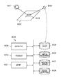
- FIG. 1 is an image diagram of vegetation index calculation by the vegetation index calculation apparatus 100 according to the present embodiment.
- the vegetation index calculating apparatus 100 includes a flying object 101, an imaging unit 102 attached to the flying object 101, and a control unit (not shown).
- the vegetation index calculating apparatus 100 uses the imaging unit 102 to acquire a spectrum of irradiation light 103a irradiated on the ground surface 104 from a light source 103 such as the sun (hereinafter referred to as irradiation spectrum), and reflected light reflected on the ground surface 104.
- a spectrum 103b (hereinafter referred to as a reflection spectrum) is acquired.
- the control unit calculates a vegetation index of the ground surface 104 using the irradiation spectrum and the reflection spectrum.
- FIGS. 2 is a flowchart for calculating a vegetation index
- FIGS. 3A to 3E are explanatory diagrams of spectra
- FIG. 4 is a relationship between a vegetation index NDVI (Normalized Difference Vegetation Index) and a detected object.
- FIG. 5 is an example of spectrum imaging by the vegetation index calculating apparatus 100.
- Step S1 in FIG. 2 is an irradiation spectrum acquisition step.
- an irradiation spectrum irradiated from the light source 103 to the ground surface 104 is acquired using the imaging unit 102.
- the imaging unit 102 uses a camera capable of acquiring a spectrum from visible light to near infrared (about 400 nm to 1000 nm).
- FIG. 3A is a spectrum diagram of pixel sensitivity of the imaging unit 102 in the present embodiment. In the figure, the horizontal axis represents wavelength, and the vertical axis represents pixel sensitivity.
- the pixel sensitivity of the imaging unit 102 has a substantially flat sensitivity from visible light to near-infrared (IR). .
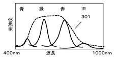
- 3B is a diagram showing an irradiation spectrum of sunlight on the ground surface 104 in the present embodiment.
- the horizontal axis represents the wavelength
- the vertical axis represents the light intensity.
- the irradiation spectrum 301 (broken line)
- the light intensity in the green band and the red band is strong
- the light intensity in the blue band and the near infrared band is weak.
- the spectrum (solid line) acquired by the imaging unit 102 also has a strong green band and a red band, and a weak blue band and a near infrared band.
- the irradiation spectrum of the sunlight irradiated to the ground surface 104 is not the solar radiation spectrum itself which is the light source 103, but before reaching the ground surface 104 or the vegetation index calculating device 100, dust, water vapor, It is affected by reflection or absorption by gases such as ozone and carbon dioxide. Further, this atmospheric state changes depending on the climate and weather (rain, cloudiness, yellow sand, etc.).
- the irradiation spectrum acquisition step S ⁇ b> 1 the spectrum of the irradiation light that is actually irradiated on the ground surface 104 or the vegetation index calculating device 100 is acquired.
- the reflection spectrum reflected by the ground surface 104 is acquired using the imaging unit 102.
- plants absorb blue and red wavelengths and strongly reflect near-infrared wavelengths by chlorophyll contained in chloroplasts.
- the reflectance 303 of the ground surface in a good vegetation state is small in the blue band and the red band, the green band is relatively large, and the near infrared band is further large. Therefore, if the irradiation spectrum is flat, the reflection spectrum of the vegetation area is the same as the reflectance 303.
- the irradiation spectrum is not flat, and varies greatly depending on weather conditions and time zones. In particular, when a small aircraft having a flight altitude of 1000 meters or less is used as the flying object 101, it is easily affected by weather conditions.
- FIG. 3D shows an irradiation spectrum 301 and a reflection spectrum 304 acquired by the imaging unit 102.
- the reflectance 303 is large in the near infrared band, the near infrared band is suppressed by the influence of the irradiation spectrum, and as a result, a spectrum distribution like the reflection spectrum 304 is obtained.
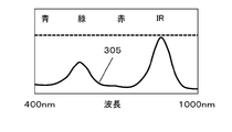
- the reflection spectrum 304 is calibrated using the irradiation spectrum 301.
- the signal output value of the reflection spectrum 304 is divided by the signal output value of the irradiation spectrum 301 for each spectrum decomposed in a predetermined range.
- the reflection spectrum 304 is normalized, and a post-calibration spectrum 305 in which the influence of the irradiation spectrum 301 is reduced can be obtained.
- NDVI is used as the vegetation index.
- NDVI is an index indicating the distribution status and activity of vegetation, and is defined as the following formula 1, using the property that healthy plants strongly reflect near-infrared light near 700 nm.
- NIR is the signal intensity in the near infrared band
- Red is the signal intensity in the red band.
- FIG. 4 is a diagram showing the relationship between NDVI and detected objects.
- the NDVI is around +1 for healthy plants such as rainforests, NDVI is 0 to +0.5 for shrubs and grasslands, and -0.5 to for deserts and snowy fields. For rivers, lakes, water, etc., it is around -1.
- NDVI used as a standard as a vegetation index
- Enhanced NDVI using signal intensity in the green band and blue band and other indices have been proposed.
- the vegetation index of the present invention is not limited to NDVI, and any index using the reflection spectrum of the ground surface can be adopted.
- FIG. 5 shows an example of spectrum imaging by the vegetation index calculating device 100.
- the aircraft is inverted as in the flying state A, and imaging is performed so that at least a part of the sky is included in the imaging range of the imaging unit 102.
- the imaging range of the imaging unit 102 does not necessarily include the light source 103 such as the sun or the direction directly above the ground surface, and may include a part of the sky serving as a calibration reference. Note that if a large light intensity exceeding the dynamic range of the imaging unit 102 is input, the acquired spectrum is distorted, so it is desirable to perform imaging so that the light source 103 does not enter the imaging range.
- the aircraft is returned to its original state as in the flying state B, and the imaging unit 102 is imaged toward the ground surface 104 (vegetation region that is an observation target).
- the ground surface 104 vehicle region that is an observation target.
- step S2 is performed after the irradiation spectrum acquisition step S1, step S1 and step S2 may be reversed. That is, in the embodiment of FIG. 5, the ground surface 104 may be imaged first as the flight state B, and then the light source 103 may be imaged as the flight state A.
- the irradiation spectrum acquisition step S1 and the reflection spectrum acquisition step S2 need not be performed as a series of operations. For example, in the first flight by the flying object 101, at least a part of the sky is imaged to obtain an irradiation spectrum, and after landing once, each region of the surface 104 is imaged in the second flight. A reflection spectrum may be acquired. Further, even in the case of performing a single flight, the irradiation spectrum may be acquired only once, and the reflection spectrum from the ground surface 104 may be acquired a plurality of times for each region. In a small airplane using a battery, the flight time is limited to several tens of minutes, so it is desirable to efficiently acquire the spectrum in this way.
- the vegetation index calculation method and the vegetation index calculation device have been described, but not limited to vegetation, the state of the ocean, lakes, and rivers, the state of the desert and snowfield, the state of the building, It can be applied to calculate various surface condition indicators, such as grasping the status of natural disasters such as earthquakes and volcanoes.
- Such index calculation also includes an irradiation spectrum acquisition step for acquiring an irradiation spectrum and a reflection spectrum acquisition step for acquiring a reflection spectrum of the ground surface by irradiation light.
- a calibration step for calibrating the reflection spectrum of the ground surface using the irradiation spectrum and a step for calculating an indicator of the ground surface state based on the post-calibration spectrum obtained by the calibration step, to obtain a spectrum with reduced influence of the irradiation spectrum
- FIG. 6 shows another embodiment of spectrum imaging by the vegetation index calculating apparatus 100.
- the vegetation index calculating apparatus 100 includes a reflector 601 attached to the flying object 101.
- the reflection plate 601 has a movable mechanism.
- irradiation spectrum acquisition step S 1 the reflecting plate 601 is moved between the imaging unit 102 and the ground surface 104 by the movable mechanism of the reflecting plate 601. At this time, adjustment is made so that the irradiation light 103 a from the light source 103 is reflected by the reflection plate 601 and enters the imaging unit 102. Thereafter, the imaging unit 102 images the reflection plate 601.
- the reflection spectrum acquisition step S ⁇ b> 2 the reflecting plate 601 is moved by the movable mechanism of the reflecting plate 601 so as not to enter between the imaging unit 102 and the ground surface 104. Then, the ground surface 104 is imaged by the imaging unit 102.
- the reflector 601 is preferably made of a material having a high reflectance in the region of 400 to 1000 ⁇ m and a flat spectral characteristic or a known spectral characteristic.
- an irradiation spectrum may be acquired using the reflector 601 before take-off by the flying object 101, and each region of the ground surface 104 may be imaged after take-off to obtain a reflection spectrum of each region.
- the acquisition spectrum may be acquired only once and the reflection spectrum may be acquired a plurality of times for each region. In a small airplane using a battery, the flight time is limited to several tens of minutes, so it is desirable to efficiently acquire the spectrum in this way.
- FIG. 7 shows another embodiment of spectrum imaging by the vegetation index calculating apparatus 100.
- the imaging unit 102 includes two imaging units, an imaging unit 102a and an imaging unit 102b.
- the imaging unit 102a is attached to a place where the sky can be easily imaged, such as the front or upper part of the flying object 101, for example.
- the imaging unit 102b is attached to a place where the ground surface is easily imaged, such as the lower surface of the flying object 101, for example.
- step S1 At least a part of the sky is imaged using the imaging unit 102a. Further, in the reflection spectrum acquisition step S2, at least a part of the ground surface 104 is imaged using the imaging unit 102b.
- step S1 and step S2 may be performed sequentially or simultaneously.
- imaging can be performed in a short time without performing the turning operation of the flying object 101 and the control of the reflector 601.
- the resolution of the imaging unit 102a may be lower than the resolution of the imaging unit 102b. This is because the image capturing unit 102a that captures the light source 103 is used for calibration, and therefore the resolution may be lower than that of the image capturing unit 102b that captures the ground surface 104 to be investigated. Thereby, the cost of the vegetation index calculating device 100 can be reduced.
- the acquisition spectrum may be acquired only once by the imaging unit 102a, and the reflection spectrum may be acquired by the imaging unit 102b a plurality of times for each region.
- the flight time is limited to several tens of minutes, so it is desirable to efficiently acquire the spectrum in this way.
- the vegetation index calculation method and the vegetation index calculation apparatus of the present disclosure can obtain a spectrum with reduced influence of the irradiation spectrum and can calculate a more accurate vegetation index, satellites and UAVs (Unmanned Aerial Vehicles) can be obtained. This is useful for indexing the vegetation state using).
- UAVs Unmanned Aerial Vehicles
Abstract
A vegetation index calculation method for calculating a vegetation index indicating the vegetation state of a surface of the earth using an imaging unit and air vehicle, said method having an irradiation spectrum acquisition step for acquiring the spectrum of irradiation light irradiated onto the surface of the earth and a reflection spectrum acquisition step for obtaining the reflection spectrum from the surface of the earth resulting from the irradiation light. The method is further provided with a correction step for correcting the reflection spectrum using the irradiation spectrum and a step for calculating a vegetation index for the surface of the earth on the basis of the corrected spectrum obtained in the correction step.
Description
本開示は、主に農作物の分布状況や育成具合を判断するために、農地の植生状態を指標化する植生指標算出方法および植生指標算出装置に関する。
The present disclosure relates to a vegetation index calculating method and a vegetation index calculating apparatus for indexing the vegetation state of farmland mainly in order to determine the distribution status and the growing condition of farm products.
図8は従来の植生指標算出方法および植生指標算出装置を示す図である。この図において、飛行体に搭載されたイメージセンサ800は、光源801に照らされた地表802の対象エリア803を撮影する。イメージセンサ800は多重スペクトル画像又はハイパースペクトル画像を撮影できる。一般に、植物は、葉緑体に含まれるクロロフィルにより、青帯域と赤帯域の波長を吸収し、近赤外帯域の波長を強く反射する。このため、地表からの反射光のスペクトルを用いて地表の植生状態を分析できる。イメージセンサ800により撮影された画像はコンピュータ804の入出力809を介してメモリ805に保存される。ここで、飛行体により上空から地表を撮影した画像は、大気中のエアロゾルが光源からの照射光又は反射光を散乱又は吸収するため、地表の正確なスペクトルが得られない。そこで、地表のタイプごとに予め準備した校正データベース806や、エアロゾルタイプごとに予め準備した校正データベース807を用いて校正を行っている。校正はプログラムメモリ808に格納されたプログラムおよびプロセッサ810、メモリ811により実行され、メモリ805に格納された撮影画像に対して校正データベース806、807を用いて校正し、校正後の画像をスペクトル分析を行うことにより、植生指標を算出している。
FIG. 8 shows a conventional vegetation index calculating method and vegetation index calculating apparatus. In this figure, an image sensor 800 mounted on a flying object photographs a target area 803 of the ground surface 802 illuminated by a light source 801. The image sensor 800 can capture a multispectral image or a hyperspectral image. In general, plants absorb blue and red wavelengths and strongly reflect near-infrared wavelengths by chlorophyll contained in chloroplasts. For this reason, the vegetation state of the ground surface can be analyzed using the spectrum of the reflected light from the ground surface. An image photographed by the image sensor 800 is stored in the memory 805 via the input / output 809 of the computer 804. Here, an image obtained by photographing the ground surface from above with a flying object cannot obtain an accurate spectrum of the ground surface because the aerosol in the atmosphere scatters or absorbs the irradiation light or reflected light from the light source. Therefore, calibration is performed using a calibration database 806 prepared in advance for each surface type or a calibration database 807 prepared in advance for each aerosol type. The calibration is executed by the program stored in the program memory 808, the processor 810, and the memory 811. The captured image stored in the memory 805 is calibrated using the calibration databases 806 and 807, and the calibrated image is subjected to spectrum analysis. By doing so, the vegetation index is calculated.
しかしながら、地表の反射スペクトルに影響を与えるのは大気中のエアロゾルのみでなく、光源である太陽光からの照射スペクトルも大きな影響を与える。太陽光からの照射スペクトルは、気象条件や時間帯により変化するため、正確な植生指標算出が困難となる。
However, it is not only the aerosol in the atmosphere that affects the reflection spectrum of the ground surface, but also the irradiation spectrum from sunlight, which is the light source, has a large effect. Since the irradiation spectrum from sunlight changes according to weather conditions and time zones, accurate vegetation index calculation becomes difficult.
上記課題を解決するため、本発明は、撮像部を有する飛行体を用いて地表の植生状態を示す植生指標を算出する方法であって、地表に照射される照射光のスペクトルを取得する照射スペクトル取得ステップと、照射光による地表の反射スペクトルを取得する反射スペクトル取得ステップと、を有する。そして、照射スペクトルを用いて反射スペクトルを校正する校正ステップと、前記校正ステップにより得られた校正後スペクトルに基づき、地表の植生指標を算出するステップと、を有する植生指標算出方法である。
In order to solve the above problems, the present invention is a method for calculating a vegetation index indicating a vegetation state on the ground surface using a flying object having an imaging unit, and obtaining an irradiation spectrum for irradiating the surface of the irradiation light. An acquisition step, and a reflection spectrum acquisition step of acquiring a reflection spectrum of the ground surface by irradiation light. And it is a vegetation index calculation method which has a calibration step which calibrates a reflection spectrum using an irradiation spectrum, and a step of calculating a vegetation index on the ground surface based on a spectrum after calibration obtained by the calibration step.
上記方法により、光源からの照射スペクトルの影響を低減したスペクトルを得ることができ、より正確な植生指標を算出することが可能となる。
The above method makes it possible to obtain a spectrum in which the influence of the irradiation spectrum from the light source is reduced, and to calculate a more accurate vegetation index.
(本開示にかかる発明に至る発明者らの知見)
図9は、太陽光からの照射スペクトルがもたらす影響のイメージ図である。グラフ901は、照射スペクトルの影響がない場合(照射スペクトルがフラットである場合)の地表の反射スペクトルである。地表の植物は、青帯域(約450~495nm)と赤帯域(約620~750nm)の波長を吸収するため反射率が小さく、緑帯域(約495~570nm)は反射率が少し強く、近赤外帯域(約750~1000nm)は反射率が非常に強い。グラフ902は朝の時間帯における太陽光からの照射スペクトルであり、グラフ903はこの時間帯における地表の反射スペクトルである。グラフ902に示すように、朝の時間帯の照射スペクトルは、赤帯域~近赤外帯域の光強度が弱くなっているため、グラフ903のように、反射スペクトルは、赤帯域~IR帯域が実際よりも小さい光強度となる。一方、グラフ904は夕方の時間帯における太陽光スペクトルであり、グラフ905はこの時間帯における地表の反射スペクトルである。グラフ904に示すように、夕方の時間帯の照射スペクトルは、青帯域~緑帯域の光強度が弱くなっているため、グラフ905のように、反射スペクトルは、青帯域~緑帯域が実際よりも小さい光強度となる。 (Knowledge of the inventors leading to the invention according to the present disclosure)
FIG. 9 is an image diagram of the influence caused by the irradiation spectrum from sunlight. Agraph 901 is a reflection spectrum of the ground surface when there is no influence of the irradiation spectrum (when the irradiation spectrum is flat). The plant on the surface absorbs wavelengths in the blue band (about 450 to 495 nm) and red band (about 620 to 750 nm), so the reflectance is small, and the green band (about 495 to 570 nm) has a slightly strong reflectance, and the near red The outer band (about 750 to 1000 nm) has a very strong reflectance. A graph 902 is an irradiation spectrum from sunlight in the morning time zone, and a graph 903 is a reflection spectrum of the ground surface in this time zone. As shown in the graph 902, the irradiation spectrum in the morning time zone has a weak light intensity in the red band to the near-infrared band. Therefore, as shown in the graph 903, the reflection spectrum is actually in the red band to the IR band. Less light intensity. On the other hand, a graph 904 is a sunlight spectrum in the evening time zone, and a graph 905 is a reflection spectrum of the ground surface in this time zone. As shown in the graph 904, the irradiation spectrum in the evening time zone is weak in the light intensity in the blue band to the green band. Therefore, as shown in the graph 905, the reflection spectrum is higher in the blue band to the green band than the actual one. The light intensity is low.
図9は、太陽光からの照射スペクトルがもたらす影響のイメージ図である。グラフ901は、照射スペクトルの影響がない場合(照射スペクトルがフラットである場合)の地表の反射スペクトルである。地表の植物は、青帯域(約450~495nm)と赤帯域(約620~750nm)の波長を吸収するため反射率が小さく、緑帯域(約495~570nm)は反射率が少し強く、近赤外帯域(約750~1000nm)は反射率が非常に強い。グラフ902は朝の時間帯における太陽光からの照射スペクトルであり、グラフ903はこの時間帯における地表の反射スペクトルである。グラフ902に示すように、朝の時間帯の照射スペクトルは、赤帯域~近赤外帯域の光強度が弱くなっているため、グラフ903のように、反射スペクトルは、赤帯域~IR帯域が実際よりも小さい光強度となる。一方、グラフ904は夕方の時間帯における太陽光スペクトルであり、グラフ905はこの時間帯における地表の反射スペクトルである。グラフ904に示すように、夕方の時間帯の照射スペクトルは、青帯域~緑帯域の光強度が弱くなっているため、グラフ905のように、反射スペクトルは、青帯域~緑帯域が実際よりも小さい光強度となる。 (Knowledge of the inventors leading to the invention according to the present disclosure)
FIG. 9 is an image diagram of the influence caused by the irradiation spectrum from sunlight. A
このように、太陽光からの照射スペクトルは、時間帯により変化するため、正確な植生指標算出が困難となる。
Thus, since the irradiation spectrum from sunlight changes depending on the time zone, it is difficult to calculate an accurate vegetation index.
また、太陽光からの照射スペクトルは、気象条件によっても変化する。そのため、正確な植生指標算出が困難となる。
Also, the irradiation spectrum from sunlight changes depending on weather conditions. This makes it difficult to calculate an accurate vegetation index.
以下、本開示の実施の形態について図面を参照しながら説明する。
Hereinafter, embodiments of the present disclosure will be described with reference to the drawings.
(実施の形態1)
図1は、本実施の形態の植生指標算出装置100による植生指標算出のイメージ図である。植生指標算出装置100は、飛行体101と、この飛行体101に取り付けられた撮像部102と、制御部(図示せず)と、を備えている。植生指標算出装置100は、撮像部102を用いて、太陽等の光源103から地表104に照射される照射光103aのスペクトル(以下、照射スペクトル)を取得するとともに、地表104で反射された反射光103bのスペクトル(以下、反射スペクトル)を取得する。その後、制御部において、照射スペクトルおよび反射スペクトルを用いて地表104の植生指標を算出する。 (Embodiment 1)
FIG. 1 is an image diagram of vegetation index calculation by the vegetationindex calculation apparatus 100 according to the present embodiment. The vegetation index calculating apparatus 100 includes a flying object 101, an imaging unit 102 attached to the flying object 101, and a control unit (not shown). The vegetation index calculating apparatus 100 uses the imaging unit 102 to acquire a spectrum of irradiation light 103a irradiated on the ground surface 104 from a light source 103 such as the sun (hereinafter referred to as irradiation spectrum), and reflected light reflected on the ground surface 104. A spectrum 103b (hereinafter referred to as a reflection spectrum) is acquired. Thereafter, the control unit calculates a vegetation index of the ground surface 104 using the irradiation spectrum and the reflection spectrum.
図1は、本実施の形態の植生指標算出装置100による植生指標算出のイメージ図である。植生指標算出装置100は、飛行体101と、この飛行体101に取り付けられた撮像部102と、制御部(図示せず)と、を備えている。植生指標算出装置100は、撮像部102を用いて、太陽等の光源103から地表104に照射される照射光103aのスペクトル(以下、照射スペクトル)を取得するとともに、地表104で反射された反射光103bのスペクトル(以下、反射スペクトル)を取得する。その後、制御部において、照射スペクトルおよび反射スペクトルを用いて地表104の植生指標を算出する。 (Embodiment 1)
FIG. 1 is an image diagram of vegetation index calculation by the vegetation
本実施の形態を用いた具体的な植生指標算出方法について、図2から図4を用いて説明する。図2は植生指標を算出するためのフローチャートであり、図3A~Eはスペクトルの説明図であり、図4は植生指標であるNDVI(Normalized Difference Vegetation Index、正規化植生指数)と検出物の関係図であり、図5は植生指標算出装置100によるスペクトル撮影の実施例である。
A specific vegetation index calculation method using the present embodiment will be described with reference to FIGS. 2 is a flowchart for calculating a vegetation index, FIGS. 3A to 3E are explanatory diagrams of spectra, and FIG. 4 is a relationship between a vegetation index NDVI (Normalized Difference Vegetation Index) and a detected object. FIG. 5 is an example of spectrum imaging by the vegetation index calculating apparatus 100. FIG.
図2のステップS1は照射スペクトル取得ステップであり、このステップでは、撮像部102を用いて光源103から地表104に照射される照射スペクトルを取得する。撮像部102は、可視光から近赤外(約400nm~1000nm)までのスペクトルを取得できるカメラを用いる。図3Aは、本実施の形態における撮像部102の画素感度のスペクトル図である。同図において、横軸は波長、縦軸は画素感度であり、撮像部102の画素感度は可視光から近赤外(infra-red、略してIR)において、ほぼフラットな感度を有している。図3Bは、本実施の形態における地表104での太陽光の照射スペクトルを表した図である。同図において、横軸は波長、縦軸は光強度であり、照射スペクトル301(破線)は、緑帯域および赤帯域の光強度が強く、青帯域及び近赤外帯域の光強度が弱い。このため、撮像部102で取得したスペクトル(実線)も同様に緑帯域および赤帯域が強く、青帯域及び近赤外帯域が弱くなる。
Step S1 in FIG. 2 is an irradiation spectrum acquisition step. In this step, an irradiation spectrum irradiated from the light source 103 to the ground surface 104 is acquired using the imaging unit 102. The imaging unit 102 uses a camera capable of acquiring a spectrum from visible light to near infrared (about 400 nm to 1000 nm). FIG. 3A is a spectrum diagram of pixel sensitivity of the imaging unit 102 in the present embodiment. In the figure, the horizontal axis represents wavelength, and the vertical axis represents pixel sensitivity. The pixel sensitivity of the imaging unit 102 has a substantially flat sensitivity from visible light to near-infrared (IR). . FIG. 3B is a diagram showing an irradiation spectrum of sunlight on the ground surface 104 in the present embodiment. In this figure, the horizontal axis represents the wavelength, and the vertical axis represents the light intensity. In the irradiation spectrum 301 (broken line), the light intensity in the green band and the red band is strong, and the light intensity in the blue band and the near infrared band is weak. For this reason, the spectrum (solid line) acquired by the imaging unit 102 also has a strong green band and a red band, and a weak blue band and a near infrared band.
なお、地表104に照射される太陽光の照射スペクトルは、光源103である太陽の放射スペクトルそのものではなく、地表104または植生指標算出装置100に到達するまでの間に、大気中の塵や水蒸気、オゾンや二酸化炭素等のガスによる反射又は吸収の影響を受ける。さらに、この大気状態は、気候や天候(雨や曇、黄砂等)により変化する。照射スペクトル取得ステップS1においては、実際に地表104または植生指標算出装置100に照射される照射光のスペクトルを取得する。
In addition, the irradiation spectrum of the sunlight irradiated to the ground surface 104 is not the solar radiation spectrum itself which is the light source 103, but before reaching the ground surface 104 or the vegetation index calculating device 100, dust, water vapor, It is affected by reflection or absorption by gases such as ozone and carbon dioxide. Further, this atmospheric state changes depending on the climate and weather (rain, cloudiness, yellow sand, etc.). In the irradiation spectrum acquisition step S <b> 1, the spectrum of the irradiation light that is actually irradiated on the ground surface 104 or the vegetation index calculating device 100 is acquired.
図2のステップS2は反射スペクトル取得ステップであり、このステップでは、撮像部102を用いて地表104で反射された反射スペクトルを取得する。一般に、植物は、葉緑体に含まれるクロロフィルにより、青帯域と赤帯域の波長を吸収し、近赤外帯域の波長を強く反射する。このため、図3Cに示すように、植生状態が良い地表の反射率303は、青帯域と赤帯域で小さく、緑帯域は比較的大きく、近赤外帯域はさらに大きい。したがって、仮に照射スペクトルがフラットである場合、植生地域の反射スペクトルは、反射率303と同様のスペクトルとなる。しかし、一般に、照射スペクトルはフラットではなく、さらに、気象条件や時間帯により大きく変化する。特に、飛行体101として、飛行高度が千メートル以下の小型飛行機を用いる場合は、気象条件の影響を受けやすくなる。
2 is a reflection spectrum acquisition step, and in this step, the reflection spectrum reflected by the ground surface 104 is acquired using the imaging unit 102. In general, plants absorb blue and red wavelengths and strongly reflect near-infrared wavelengths by chlorophyll contained in chloroplasts. For this reason, as shown in FIG. 3C, the reflectance 303 of the ground surface in a good vegetation state is small in the blue band and the red band, the green band is relatively large, and the near infrared band is further large. Therefore, if the irradiation spectrum is flat, the reflection spectrum of the vegetation area is the same as the reflectance 303. However, in general, the irradiation spectrum is not flat, and varies greatly depending on weather conditions and time zones. In particular, when a small aircraft having a flight altitude of 1000 meters or less is used as the flying object 101, it is easily affected by weather conditions.
図3Dは、撮像部102で取得した照射スペクトル301と、反射スペクトル304を示している。反射率303は近赤外帯域が大きいが、照射スペクトルの影響で近赤外帯域が抑圧され、その結果、反射スペクトル304のようなスペクトル分布となる。
FIG. 3D shows an irradiation spectrum 301 and a reflection spectrum 304 acquired by the imaging unit 102. Although the reflectance 303 is large in the near infrared band, the near infrared band is suppressed by the influence of the irradiation spectrum, and as a result, a spectrum distribution like the reflection spectrum 304 is obtained.
図2のステップS3は校正ステップであり、このステップでは、照射スペクトル301を用いて反射スペクトル304を校正する。校正方法としては、例えば、所定範囲で分解したスペクトルごとに、反射スペクトル304の信号出力値を照射スペクトル301の信号出力値で除算する。これにより、図3Eのように、反射スペクトル304を正規化し、照射スペクトル301の影響を低減した校正後スペクトル305を得ることができる。
2 is a calibration step, and in this step, the reflection spectrum 304 is calibrated using the irradiation spectrum 301. As a calibration method, for example, the signal output value of the reflection spectrum 304 is divided by the signal output value of the irradiation spectrum 301 for each spectrum decomposed in a predetermined range. As a result, as shown in FIG. 3E, the reflection spectrum 304 is normalized, and a post-calibration spectrum 305 in which the influence of the irradiation spectrum 301 is reduced can be obtained.
図2のステップS4は植生指標算出ステップであり、このステップでは、校正後スペクトル305に基づき、地表104の植生指標を算出する。植生指標としては、例えば、NDVIを用いる。NDVIは、植生の分布状況や活性度を示す指標で、健康な植物が700nm付近の近赤外光を強く反射する性質を利用し、次式の数1のように定義される。ここで、NIRは近赤外帯域の信号強度であり、Redは赤帯域の信号強度である。
2 is a vegetation index calculation step, and in this step, a vegetation index of the ground surface 104 is calculated based on the calibrated spectrum 305. For example, NDVI is used as the vegetation index. NDVI is an index indicating the distribution status and activity of vegetation, and is defined as the following formula 1, using the property that healthy plants strongly reflect near-infrared light near 700 nm. Here, NIR is the signal intensity in the near infrared band, and Red is the signal intensity in the red band.

図4はNDVIと検出物との関係を示す図である。地表の状態が熱帯雨林等の健康な植物の場合はNDVIが+1前後となり、低木や草原の場合はNDVIが0~+0.5となり、砂漠や雪原の場合はー0.5~となり、海や川、湖、水等の場合は-1前後となる。なお、植生指標として標準的に用いられるNDVIの説明をしたが、緑帯域や青帯域の信号強度を用いたEnhanced NDVIや、その他の指標も提案されている。本発明の植生指標としては、NDVIに限定されず、地表の反射スペクトルを用いた指標であれば採用することができる。
FIG. 4 is a diagram showing the relationship between NDVI and detected objects. The NDVI is around +1 for healthy plants such as rainforests, NDVI is 0 to +0.5 for shrubs and grasslands, and -0.5 to for deserts and snowy fields. For rivers, lakes, water, etc., it is around -1. In addition, although NDVI used as a standard as a vegetation index has been described, Enhanced NDVI using signal intensity in the green band and blue band and other indices have been proposed. The vegetation index of the present invention is not limited to NDVI, and any index using the reflection spectrum of the ground surface can be adopted.
図5は植生指標算出装置100によるスペクトル撮影の実施例である。照射スペクトル取得ステップS1において、飛行体101の制御により、飛行状態Aのように機体を反転し、撮像部102の撮像範囲に空の少なくとも一部が含まれるように撮像する。この際、撮像部102の撮像範囲には、太陽等の光源103や地表と正対する真上方向を必ずしも含む必要はなく、校正のリファレンスとなる空の一部が含まれていればよい。なお、撮像部102のダイナミックレンジを越える大きな光強度が入力されると、取得したスペクトラムが歪んでしまうため、光源103が撮像範囲に入らないように撮像することが望ましい。次に、飛行体101の制御により、飛行状態Bのように機体を元に戻し、撮像部102を地表104(観測対象である植生領域)に向けて撮像する。このように飛行体101の制御により空の少なくとも一部と、地表104の少なくとも一部を二段階で撮像することにより、1つの撮像部で照射スペクトルと反射スペクトルを取得することができる。このため、複数のカメラを用いる場合と比べて低コスト化できるとともに、複数カメラ間のスペクトル特性の差に起因する誤差をなくすことができる。
FIG. 5 shows an example of spectrum imaging by the vegetation index calculating device 100. In the irradiation spectrum acquisition step S <b> 1, under control of the flying object 101, the aircraft is inverted as in the flying state A, and imaging is performed so that at least a part of the sky is included in the imaging range of the imaging unit 102. At this time, the imaging range of the imaging unit 102 does not necessarily include the light source 103 such as the sun or the direction directly above the ground surface, and may include a part of the sky serving as a calibration reference. Note that if a large light intensity exceeding the dynamic range of the imaging unit 102 is input, the acquired spectrum is distorted, so it is desirable to perform imaging so that the light source 103 does not enter the imaging range. Next, under the control of the flying object 101, the aircraft is returned to its original state as in the flying state B, and the imaging unit 102 is imaged toward the ground surface 104 (vegetation region that is an observation target). As described above, at least a part of the sky and at least a part of the ground surface 104 are imaged in two stages under the control of the flying object 101, so that an irradiation spectrum and a reflection spectrum can be acquired by one imaging unit. For this reason, it is possible to reduce the cost as compared with the case of using a plurality of cameras, and it is possible to eliminate an error caused by a difference in spectral characteristics between the plurality of cameras.
なお、本実施の形態においては、図2に示すように、照射スペクトル取得ステップS1の後に反射スペクトル取得ステップS2を行っているが、ステップS1とステップS2を逆にしてもよい。すなわち、図5の実施例では、最初に飛行状態Bとして地表104を撮像し、次に飛行状態Aとして光源103を撮像してもよい。
In addition, in this Embodiment, as shown in FIG. 2, although the reflection spectrum acquisition step S2 is performed after the irradiation spectrum acquisition step S1, step S1 and step S2 may be reversed. That is, in the embodiment of FIG. 5, the ground surface 104 may be imaged first as the flight state B, and then the light source 103 may be imaged as the flight state A.
なお、照射スペクトル取得ステップS1と、反射スペクトル取得ステップS2は一連の動作として行う必要はない。例えば、飛行体101による1回目の飛行で、空の少なくとも一部を撮像して照射スペクトルを取得し、一度着陸した後に、2回目の飛行で地表104の各領域をそれぞれ撮像し、各領域の反射スペクトルを取得してもよい。また、一回の飛行で行う場合であっても、照射スペクトルの取得は1回のみ行い、地表104からの反射スペクトルの取得は、各領域ごとに複数回行っても良い。電池を用いた小型飛行機では、飛行時間が数十分程度に制限されるため、このように効率的にスペクトル取得を行うのが望ましい。
The irradiation spectrum acquisition step S1 and the reflection spectrum acquisition step S2 need not be performed as a series of operations. For example, in the first flight by the flying object 101, at least a part of the sky is imaged to obtain an irradiation spectrum, and after landing once, each region of the surface 104 is imaged in the second flight. A reflection spectrum may be acquired. Further, even in the case of performing a single flight, the irradiation spectrum may be acquired only once, and the reflection spectrum from the ground surface 104 may be acquired a plurality of times for each region. In a small airplane using a battery, the flight time is limited to several tens of minutes, so it is desirable to efficiently acquire the spectrum in this way.
なお、飛行体としては、人工衛星や航空機を使用できるが、ヘリコプターやドローンなど、飛行高度が千メートル以下の低空飛行体においては特に、気象条件や時間帯による太陽光スペクトルの変化の影響を大きく受けるため、本発明が有効である。
Artificial satellites and airplanes can be used as flying objects, but the effects of changes in the solar spectrum due to weather conditions and time zones are particularly significant for low-flying objects with flying altitudes of 1000 meters or less, such as helicopters and drones. Therefore, the present invention is effective.
なお、本実施の形態においては、植生指標算出方法および植生指標算出装置について説明したが、植生に限らず、海洋や湖沼、河川の状態把握、砂漠や雪原の状態把握、建築物の状況把握、地震や火山等の自然災害の状況把握など、様々な地表状態の指標算出に応用できる。このような指標算出においても、照射スペクトルを取得する照射スペクトル取得ステップと、照射光による地表の反射スペクトルを取得する反射スペクトル取得ステップと、を有する。さらに照射スペクトルを用いて地表の反射スペクトルを校正する校正ステップと、校正ステップにより得られた校正後スペクトルに基づき、地表状態の指標を算出するステップにより、照射スペクトルの影響を低減したスペクトルを得ることができ、より正確な地表状態の指標を算出することが可能となる。
In this embodiment, the vegetation index calculation method and the vegetation index calculation device have been described, but not limited to vegetation, the state of the ocean, lakes, and rivers, the state of the desert and snowfield, the state of the building, It can be applied to calculate various surface condition indicators, such as grasping the status of natural disasters such as earthquakes and volcanoes. Such index calculation also includes an irradiation spectrum acquisition step for acquiring an irradiation spectrum and a reflection spectrum acquisition step for acquiring a reflection spectrum of the ground surface by irradiation light. Furthermore, a calibration step for calibrating the reflection spectrum of the ground surface using the irradiation spectrum, and a step for calculating an indicator of the ground surface state based on the post-calibration spectrum obtained by the calibration step, to obtain a spectrum with reduced influence of the irradiation spectrum Thus, it is possible to calculate a more accurate index of the surface condition.
(実施の形態2)
本実施の形態の実施の形態の特徴部分について、実施の形態1との相違点を中心に説明する。 (Embodiment 2)
The features of the present embodiment will be described focusing on the differences from the first embodiment.
本実施の形態の実施の形態の特徴部分について、実施の形態1との相違点を中心に説明する。 (Embodiment 2)
The features of the present embodiment will be described focusing on the differences from the first embodiment.
図6は、植生指標算出装置100によるスペクトル撮影の他の実施例である。植生指標算出装置100は、飛行体101に取り付けられた反射板601を備えている。この反射板601は可動機構を備えている。
FIG. 6 shows another embodiment of spectrum imaging by the vegetation index calculating apparatus 100. The vegetation index calculating apparatus 100 includes a reflector 601 attached to the flying object 101. The reflection plate 601 has a movable mechanism.
照射スペクトル取得ステップS1において、反射板601の可動機構により、反射板601を撮像部102と地表104の間に移動させる。この際、光源103からの照射光103aが反射板601で反射して撮像部102に入光するように調整する。その後、撮像部102でこの反射板601を撮像する。次に、反射スペクトル取得ステップS2において、反射板601の可動機構により、反射板601を撮像部102と地表104の間に入らないように移動させる。その後、撮像部102で地表104を撮像する。
In irradiation spectrum acquisition step S 1, the reflecting plate 601 is moved between the imaging unit 102 and the ground surface 104 by the movable mechanism of the reflecting plate 601. At this time, adjustment is made so that the irradiation light 103 a from the light source 103 is reflected by the reflection plate 601 and enters the imaging unit 102. Thereafter, the imaging unit 102 images the reflection plate 601. Next, in the reflection spectrum acquisition step S <b> 2, the reflecting plate 601 is moved by the movable mechanism of the reflecting plate 601 so as not to enter between the imaging unit 102 and the ground surface 104. Then, the ground surface 104 is imaged by the imaging unit 102.
このように反射板601を用いて光源と被写体(地表)を二段階で撮像することにより、飛行体を旋回させることなく、1つの撮像部で照射スペクトルと反射スペクトルを取得することができる。なお、反射板601は400~1000umの領域で高反射率であり、かつ、フラットなスペクトル特性の素材またはスペクトル特性が既知の素材を用いることが望ましい。
As described above, by imaging the light source and the subject (the ground surface) in two stages using the reflector 601, it is possible to acquire the irradiation spectrum and the reflection spectrum with one imaging unit without turning the flying object. Note that the reflector 601 is preferably made of a material having a high reflectance in the region of 400 to 1000 μm and a flat spectral characteristic or a known spectral characteristic.
なお、飛行体101による離陸前に、反射板601を用いて照射スペクトルを取得し、離陸後に、地表104の各領域をそれぞれ撮像し、各領域の反射スペクトルを取得してもよい。また、ともに飛行中で行う場合であっても、照射スペクトルの取得は1回のみ行い、反射スペクトルの取得は、各領域ごとに複数回行っても良い。電池を用いた小型飛行機では、飛行時間が数十分程度に制限されるため、このように効率的にスペクトル取得を行うのが望ましい。
It should be noted that an irradiation spectrum may be acquired using the reflector 601 before take-off by the flying object 101, and each region of the ground surface 104 may be imaged after take-off to obtain a reflection spectrum of each region. Moreover, even when both are performed in flight, the acquisition spectrum may be acquired only once and the reflection spectrum may be acquired a plurality of times for each region. In a small airplane using a battery, the flight time is limited to several tens of minutes, so it is desirable to efficiently acquire the spectrum in this way.
(実施の形態3)
本実施の形態の実施の形態の特徴部分について、実施の形態1との相違点を中心に説明する。 (Embodiment 3)
The features of the present embodiment will be described focusing on the differences from the first embodiment.
本実施の形態の実施の形態の特徴部分について、実施の形態1との相違点を中心に説明する。 (Embodiment 3)
The features of the present embodiment will be described focusing on the differences from the first embodiment.
図7は、植生指標算出装置100によるスペクトル撮影の他の実施例である。同図において、撮像部102は、撮像部102aと撮像部102bの2つの撮像部で構成される。撮像部102aは、例えば、飛行体101の前部又は上部など、空を撮像しやすい場所に取り付けられている。撮像部102bは、例えば、飛行体101の下面など、地表を撮像しやすい場所に取り付けられている。
FIG. 7 shows another embodiment of spectrum imaging by the vegetation index calculating apparatus 100. In the figure, the imaging unit 102 includes two imaging units, an imaging unit 102a and an imaging unit 102b. The imaging unit 102a is attached to a place where the sky can be easily imaged, such as the front or upper part of the flying object 101, for example. The imaging unit 102b is attached to a place where the ground surface is easily imaged, such as the lower surface of the flying object 101, for example.
照射スペクトル取得ステップS1において、撮像部102aを用いて空の少なくとも一部を撮像する。また、反射スペクトル取得ステップS2において、撮像部102bを用いて地表104の少なくとも一部を撮像する。ここで、ステップS1とステップS2は順番に行っても良いし、同時に行っても良い。
In the irradiation spectrum acquisition step S1, at least a part of the sky is imaged using the imaging unit 102a. Further, in the reflection spectrum acquisition step S2, at least a part of the ground surface 104 is imaged using the imaging unit 102b. Here, step S1 and step S2 may be performed sequentially or simultaneously.
このように、2つの撮像部102a、102bを用いることにより、飛行体101の旋回動作や、反射板601の制御を行うことなく、短時間で撮像を行うことができる。
Thus, by using the two imaging units 102a and 102b, imaging can be performed in a short time without performing the turning operation of the flying object 101 and the control of the reflector 601.
なお、撮像部102aの解像度を撮像部102bの解像度よりも低くしてもよい。光源103を撮像する撮像部102aは校正用であるため、調査対象である地表104を撮像する撮像部102bよりも低解像度でよいからである。これにより、植生指標算出装置100を低コスト化することができる。
Note that the resolution of the imaging unit 102a may be lower than the resolution of the imaging unit 102b. This is because the image capturing unit 102a that captures the light source 103 is used for calibration, and therefore the resolution may be lower than that of the image capturing unit 102b that captures the ground surface 104 to be investigated. Thereby, the cost of the vegetation index calculating device 100 can be reduced.
なお、撮像部102aによる照射スペクトルの取得は1回のみ行い、撮像部102bによる反射スペクトルの取得は、各領域ごとに複数回行っても良い。電池を用いた小型飛行機では、飛行時間が数十分程度に制限されるため、このように効率的にスペクトル取得を行うのが望ましい。
The acquisition spectrum may be acquired only once by the imaging unit 102a, and the reflection spectrum may be acquired by the imaging unit 102b a plurality of times for each region. In a small airplane using a battery, the flight time is limited to several tens of minutes, so it is desirable to efficiently acquire the spectrum in this way.
本開示の植生指標算出方法および植生指標算出装置は、照射スペクトルの影響を低減したスペクトルを得ることができ、より正確な植生指標を算出することが可能となるため、衛星やUAV(Unmanned Aerial Vehicle)等を用いた植生状態の指標化に有用である。
Since the vegetation index calculation method and the vegetation index calculation apparatus of the present disclosure can obtain a spectrum with reduced influence of the irradiation spectrum and can calculate a more accurate vegetation index, satellites and UAVs (Unmanned Aerial Vehicles) can be obtained. This is useful for indexing the vegetation state using).
100 植生指標算出装置
101 飛行体
102,102a,102b 撮像部
103 光源
103a 照射光
103b 反射光
104 地表
301 照射スペクトル
303 反射率
304 反射スペクトル
305 校正後スペクトル
601 反射板 DESCRIPTION OFSYMBOLS 100 Vegetation parameter | index calculation apparatus 101 Flight body 102,102a, 102b Image pick-up part 103 Light source 103a Irradiation light 103b Reflected light 104 Ground surface 301 Irradiation spectrum 303 Reflectivity 304 Reflection spectrum 305 Spectrum after calibration 601 Reflector
101 飛行体
102,102a,102b 撮像部
103 光源
103a 照射光
103b 反射光
104 地表
301 照射スペクトル
303 反射率
304 反射スペクトル
305 校正後スペクトル
601 反射板 DESCRIPTION OF
Claims (10)
- 撮像部および飛行体を用いて地表の植生状態を示す植生指標を算出する方法であって、
前記地表に照射される照射光のスペクトルを取得する照射スペクトル取得ステップと、
前記照射光による前記地表の反射スペクトルを取得する反射スペクトル取得ステップと、
前記照射スペクトルを用いて前記反射スペクトルを校正する校正ステップと、
前記校正ステップにより得られた校正後スペクトルに基づき、前記地表の植生指標を算出するステップと、
を有する植生指標算出方法。 A method for calculating a vegetation index indicating a vegetation state on the ground surface using an imaging unit and a flying object,
An irradiation spectrum acquisition step of acquiring a spectrum of irradiation light irradiated on the ground surface;
A reflection spectrum acquisition step of acquiring a reflection spectrum of the ground surface by the irradiation light;
A calibration step of calibrating the reflection spectrum using the irradiation spectrum;
Based on the post-calibration spectrum obtained by the calibration step, calculating a vegetation index of the surface,
A method for calculating a vegetation index. - 前記照射スペクトル取得ステップは、前記飛行体の制御により、前記撮像部にて空の少なくとも一部を撮像することにより照射光のスペクトルを取得し、
前記反射スペクトル取得ステップは、前記飛行体の制御により、前記撮像部にて前記地表の少なくとも一部を撮像することにより前記地表の反射スペクトルを取得する、請求項1に記載の植生指標算出方法。 The irradiation spectrum acquisition step acquires the spectrum of irradiation light by imaging at least a part of the sky by the imaging unit under the control of the flying object,
The vegetation index calculation method according to claim 1, wherein the reflection spectrum acquisition step acquires the reflection spectrum of the ground surface by imaging at least a part of the ground surface by the imaging unit under the control of the flying object. - 前記照射光を反射する反射板が前記飛行体に設けられ、
前記照射スペクトル取得ステップは、前記撮像部を用いて前記反射板を撮像することにより照射光のスペクトルを取得し、
前記反射スペクトル取得ステップは、前記撮像部を用いて前記地表を撮像することにより前記地表の反射スペクトルを取得する、請求項1に記載の植生指標算出方法。 A reflector for reflecting the irradiation light is provided on the flying body,
The irradiation spectrum acquisition step acquires the spectrum of irradiation light by imaging the reflector using the imaging unit,
The vegetation index calculation method according to claim 1, wherein the reflection spectrum acquisition step acquires a reflection spectrum of the ground surface by imaging the ground surface using the imaging unit. - 前記反射板は可動機構を備え、
前記照射スペクトル取得ステップは、前記撮像部による撮像の前に、前記反射板を前記撮像部と前記地表の間に移動させる、請求項3に記載の植生指標算出方法。 The reflector includes a movable mechanism,
The vegetation index calculation method according to claim 3, wherein the irradiation spectrum acquisition step moves the reflecting plate between the imaging unit and the ground surface before imaging by the imaging unit. - 前記撮像部は、空の少なくとも一部を撮像できる位置に設けられた第1の撮像部と、前記地表の少なくとも一部を撮像できる位置に設けられた第2の撮像部と、を備え、
前記照射スペクトル取得ステップは、前記第1の撮像部を用いて空の少なくとも一部を撮像することにより照射光のスペクトルを取得し、
前記反射スペクトル取得ステップは、前記第2の撮像部を用いて前記地表の少なくとも一部を撮像することにより前記地表の反射スペクトルを取得する、請求項1に記載の植生指標算出方法。 The imaging unit includes a first imaging unit provided at a position where at least a part of the sky can be imaged, and a second imaging unit provided at a position where at least a part of the ground surface can be imaged,
The irradiation spectrum acquisition step acquires a spectrum of irradiation light by imaging at least a part of the sky using the first imaging unit,
The vegetation index calculation method according to claim 1, wherein the reflection spectrum acquisition step acquires a reflection spectrum of the ground surface by imaging at least a part of the ground surface using the second imaging unit. - 地表の植生状態を算出する植生指標算出装置であって、
前記植生指標算出装置は、飛行体部と、撮像部と、制御部を備え、
前記撮像部は照射光の照射スペクトルおよび前記照射光による前記地表の反射スペクトルを取得し、
前記制御部は、前記照射スペクトルを用いて前記反射スペクトルを校正して校正後スペクトルを算出し、前記校正後スペクトルに基づき前記地表の植生指標を算出する植生指標算出装置。 A vegetation index calculating device for calculating the vegetation state of the ground surface,
The vegetation index calculating device includes a flying body unit, an imaging unit, and a control unit,
The imaging unit obtains an irradiation spectrum of irradiation light and a reflection spectrum of the ground surface by the irradiation light,
The said control part calibrates the said reflection spectrum using the said irradiation spectrum, calculates a post-calibration spectrum, The vegetation index calculation apparatus which calculates the vegetation index of the said ground based on the said post-calibration spectrum. - 前記飛行体部は、前記撮像部が照射光のスペクトルを取得する際は前記撮像部の撮像範囲に空の少なくとも一部が含まれるように飛行制御を行い、前記撮像部が地表の反射スペクトルを取得する際は前記撮像部の撮像範囲に前記地表の少なくとも一部が含まれるように飛行制御を行う請求項6に記載の植生指標算出装置。 When the imaging unit acquires the spectrum of irradiation light, the flying unit performs flight control so that the imaging range of the imaging unit includes at least a part of the sky, and the imaging unit calculates the reflection spectrum of the ground surface. The vegetation index calculating device according to claim 6, wherein when acquiring, the flight control is performed so that at least a part of the ground surface is included in an imaging range of the imaging unit.
- 前記植生指標算出装置は前記照射光を反射する反射板を備え、
前記撮像部は前記反射板を撮像することにより照射光のスペクトルを取得する請求項6に記載の植生指標算出装置。 The vegetation index calculating device includes a reflector that reflects the irradiation light,
The vegetation index calculating apparatus according to claim 6, wherein the imaging unit acquires a spectrum of irradiation light by imaging the reflection plate. - 前記反射板は可動機構を備え、
前記撮像部による前記反射板の撮像の前に、前記反射板を前記撮像部と前記地表の間に移動させる、請求項8に記載の植生指標算出装置。 The reflector includes a movable mechanism,
The vegetation index calculating apparatus according to claim 8, wherein the reflecting plate is moved between the imaging unit and the ground surface before the imaging of the reflecting plate by the imaging unit. - 前記撮像部は、空の少なくとも一部を撮像できる位置に設けられた第1の撮像部と、前記地表の少なくとも一部を撮像できる位置に設けられた第2の撮像部と、を備え、
前記第1の撮像部を用いて前記照射光のスペクトルを取得し、
前記第2の撮像部を用いて前記地表のスペクトルを取得する請求項6に記載の植生指標算出装置。 The imaging unit includes a first imaging unit provided at a position where at least a part of the sky can be imaged, and a second imaging unit provided at a position where at least a part of the ground surface can be imaged,
Obtaining a spectrum of the irradiation light using the first imaging unit;
The vegetation index calculating apparatus according to claim 6, wherein a spectrum of the ground surface is acquired using the second imaging unit.
Priority Applications (1)
| Application Number | Priority Date | Filing Date | Title |
|---|---|---|---|
| US15/744,955 US10386295B2 (en) | 2015-07-28 | 2016-07-19 | Vegetation index calculation method and vegetation index calculation device |
Applications Claiming Priority (2)
| Application Number | Priority Date | Filing Date | Title |
|---|---|---|---|
| US201562197852P | 2015-07-28 | 2015-07-28 | |
| US62/197,852 | 2015-07-28 |
Publications (1)
| Publication Number | Publication Date |
|---|---|
| WO2017017929A1 true WO2017017929A1 (en) | 2017-02-02 |
Family
ID=57885070
Family Applications (1)
| Application Number | Title | Priority Date | Filing Date |
|---|---|---|---|
| PCT/JP2016/003385 WO2017017929A1 (en) | 2015-07-28 | 2016-07-19 | Vegetation index calculation method and vegetation index calculation device |
Country Status (2)
| Country | Link |
|---|---|
| US (1) | US10386295B2 (en) |
| WO (1) | WO2017017929A1 (en) |
Cited By (2)
| Publication number | Priority date | Publication date | Assignee | Title |
|---|---|---|---|---|
| CN109974854A (en) * | 2019-03-18 | 2019-07-05 | 石河子大学 | A kind of radiation correction method of frame width formula FPI high spectrum image |
| JP2019178958A (en) * | 2018-03-30 | 2019-10-17 | 株式会社フジタ | Unmanned aerial vehicle and relative reflectance computation method |
Families Citing this family (2)
| Publication number | Priority date | Publication date | Assignee | Title |
|---|---|---|---|---|
| CN110967300B (en) * | 2019-12-24 | 2022-03-25 | 中央民族大学 | Hyperspectral remote sensing method for estimating species abundance of vascular plants |
| CN112016388A (en) * | 2020-07-08 | 2020-12-01 | 珠江水利委员会珠江水利科学研究院 | Vegetation information extraction method based on visible light waveband unmanned aerial vehicle remote sensing image |
Citations (4)
| Publication number | Priority date | Publication date | Assignee | Title |
|---|---|---|---|---|
| JP2004301810A (en) * | 2003-04-01 | 2004-10-28 | Ebara Corp | Growth degree measuring instrument for plant |
| JP2006101768A (en) * | 2004-10-06 | 2006-04-20 | Satake Corp | Method for sorting raw unhulled rice in reception with rice center, country elevator or the like |
| JP2006314215A (en) * | 2005-05-10 | 2006-11-24 | National Agriculture & Food Research Organization | Growth-degree measuring device for being installed on mobile body |
| JP2010256303A (en) * | 2009-04-28 | 2010-11-11 | Sumitomo Electric Ind Ltd | Hyper-spectrum image processor and hyper-spectrum image processing method |
Family Cites Families (7)
| Publication number | Priority date | Publication date | Assignee | Title |
|---|---|---|---|---|
| US5980052A (en) * | 1997-07-29 | 1999-11-09 | Thor; Leifur Hayden | Sun reflecting device |
| US20010016053A1 (en) * | 1997-10-10 | 2001-08-23 | Monte A. Dickson | Multi-spectral imaging sensor |
| CA2547359C (en) * | 2003-11-26 | 2012-11-27 | Florida Environmental Research Institute, Inc. | Spectral imaging system |
| US8558884B2 (en) | 2011-05-04 | 2013-10-15 | Raytheon Company | In-scene determination of aerosol parameters from imagery |
| US20140022381A1 (en) * | 2012-07-17 | 2014-01-23 | Tetracam, Inc. | Radiometric multi-spectral or hyperspectral camera array using matched area sensors and a calibrated ambient light collection device |
| US9542782B2 (en) * | 2014-08-25 | 2017-01-10 | Justin James Blank, SR. | Aircraft landing and takeoff logging system |
| US9470579B2 (en) * | 2014-09-08 | 2016-10-18 | SlantRange, Inc. | System and method for calibrating imaging measurements taken from aerial vehicles |
-
2016
- 2016-07-19 US US15/744,955 patent/US10386295B2/en active Active
- 2016-07-19 WO PCT/JP2016/003385 patent/WO2017017929A1/en active Application Filing
Patent Citations (4)
| Publication number | Priority date | Publication date | Assignee | Title |
|---|---|---|---|---|
| JP2004301810A (en) * | 2003-04-01 | 2004-10-28 | Ebara Corp | Growth degree measuring instrument for plant |
| JP2006101768A (en) * | 2004-10-06 | 2006-04-20 | Satake Corp | Method for sorting raw unhulled rice in reception with rice center, country elevator or the like |
| JP2006314215A (en) * | 2005-05-10 | 2006-11-24 | National Agriculture & Food Research Organization | Growth-degree measuring device for being installed on mobile body |
| JP2010256303A (en) * | 2009-04-28 | 2010-11-11 | Sumitomo Electric Ind Ltd | Hyper-spectrum image processor and hyper-spectrum image processing method |
Cited By (2)
| Publication number | Priority date | Publication date | Assignee | Title |
|---|---|---|---|---|
| JP2019178958A (en) * | 2018-03-30 | 2019-10-17 | 株式会社フジタ | Unmanned aerial vehicle and relative reflectance computation method |
| CN109974854A (en) * | 2019-03-18 | 2019-07-05 | 石河子大学 | A kind of radiation correction method of frame width formula FPI high spectrum image |
Also Published As
| Publication number | Publication date |
|---|---|
| US20180209898A1 (en) | 2018-07-26 |
| US10386295B2 (en) | 2019-08-20 |
Similar Documents
| Publication | Publication Date | Title |
|---|---|---|
| Honkavaara et al. | Remote sensing of 3-D geometry and surface moisture of a peat production area using hyperspectral frame cameras in visible to short-wave infrared spectral ranges onboard a small unmanned airborne vehicle (UAV) | |
| Yoshida et al. | Retrieval algorithm for CO 2 and CH 4 column abundances from short-wavelength infrared spectral observations by the Greenhouse gases observing satellite | |
| Chander et al. | Evaluation and comparison of the IRS-P6 and the Landsat sensors | |
| WO2017017929A1 (en) | Vegetation index calculation method and vegetation index calculation device | |
| Hunt et al. | Remote sensing of crop leaf area index using unmanned airborne vehicles | |
| CN110544277A (en) | Method for inverting subtropical vegetation leaf area index by unmanned aerial vehicle-mounted hyperspectral imager | |
| Zaman et al. | Retrieval of spectral reflectance of high resolution multispectral imagery acquired with an autonomous unmanned aerial vehicle | |
| Schneider-Zapp et al. | A new method to determine multi-angular reflectance factor from lightweight multispectral cameras with sky sensor in a target-less workflow applicable to UAV | |
| Näsi et al. | UAS based tree species identification using the novel FPI based hyperspectral cameras in visible, NIR and SWIR spectral ranges | |
| Gautam et al. | Footprint determination of a spectroradiometer mounted on an unmanned aircraft system | |
| Zhou et al. | Radiometric calibration of a large-array commodity CMOS multispectral camera for UAV-borne remote sensing | |
| Pons et al. | An empirical approach on shadow reduction of UAV imagery in forests | |
| Guillén-Climent et al. | Estimating radiation interception in heterogeneous orchards using high spatial resolution airborne imagery | |
| Tsouvaltsidis et al. | Remote spectral imaging using a low cost UAV system | |
| Yang et al. | Comparison of airborne multispectral and hyperspectral imagery for estimating grain sorghum yield | |
| Näsi et al. | Optimizing radiometric processing and feature extraction of drone based hyperspectral frame format imagery for estimation of yield quantity and quality of a grass sward | |
| Kuusk et al. | Measured spectral bidirectional reflection properties of three mature hemiboreal forests | |
| Edwards et al. | An evaluation of reflectance calibration methods for UAV spectral imagery | |
| WO2022180616A1 (en) | Estimation of a crop coefficient vector based on multispectral remote sensing | |
| CN110702228B (en) | Edge radiation correction method for aviation hyperspectral image | |
| Honkavaara et al. | Geometric and reflectance signature characterization of complex canopies using hyperspectral stereoscopic images from uav and terrestrial platforms | |
| Labbé et al. | An operational solution to acquire multispectral images with standard light cameras: Characterization and acquisition guidelines | |
| Gilliot et al. | Correction of in-flight luminosity variations in multispectral UAS images, using a luminosity sensor and camera pair for improved biomass estimation in precision agriculture | |
| Markelin et al. | Radiometric correction of multitemporal hyperspectral uas image mosaics of seedling stands | |
| Kneer et al. | A Snapshot Imaging System for the Measurement of Solar-induced Chlorophyll Fluorescence–Addressing the Challenges of High-performance Spectral Imaging |
Legal Events
| Date | Code | Title | Description |
|---|---|---|---|
| 121 | Ep: the epo has been informed by wipo that ep was designated in this application |
Ref document number: 16830035 Country of ref document: EP Kind code of ref document: A1 |
|
| WWE | Wipo information: entry into national phase |
Ref document number: 15744955 Country of ref document: US |
|
| NENP | Non-entry into the national phase |
Ref country code: DE |
|
| NENP | Non-entry into the national phase |
Ref country code: JP |
|
| 122 | Ep: pct application non-entry in european phase |
Ref document number: 16830035 Country of ref document: EP Kind code of ref document: A1 |