EP4357729B1 - Dreidimensionales zahnärztliches abtastverfahren - Google Patents
Dreidimensionales zahnärztliches abtastverfahren Download PDFInfo
- Publication number
- EP4357729B1 EP4357729B1 EP24160434.7A EP24160434A EP4357729B1 EP 4357729 B1 EP4357729 B1 EP 4357729B1 EP 24160434 A EP24160434 A EP 24160434A EP 4357729 B1 EP4357729 B1 EP 4357729B1
- Authority
- EP
- European Patent Office
- Prior art keywords
- point cloud
- scanning
- point
- dental
- section
- Prior art date
- Legal status (The legal status is an assumption and is not a legal conclusion. Google has not performed a legal analysis and makes no representation as to the accuracy of the status listed.)
- Active
Links
Images


Classifications
-
- A—HUMAN NECESSITIES
- A61—MEDICAL OR VETERINARY SCIENCE; HYGIENE
- A61C—DENTISTRY; APPARATUS OR METHODS FOR ORAL OR DENTAL HYGIENE
- A61C9/00—Impression cups, i.e. impression trays; Impression methods
- A61C9/004—Means or methods for taking digitized impressions
- A61C9/0046—Data acquisition means or methods
- A61C9/0053—Optical means or methods, e.g. scanning the teeth by a laser or light beam
-
- A—HUMAN NECESSITIES
- A61—MEDICAL OR VETERINARY SCIENCE; HYGIENE
- A61B—DIAGNOSIS; SURGERY; IDENTIFICATION
- A61B1/00—Instruments for performing medical examinations of the interior of cavities or tubes of the body by visual or photographical inspection, e.g. endoscopes; Illuminating arrangements therefor
- A61B1/00163—Optical arrangements
- A61B1/00172—Optical arrangements with means for scanning
-
- A—HUMAN NECESSITIES
- A61—MEDICAL OR VETERINARY SCIENCE; HYGIENE
- A61B—DIAGNOSIS; SURGERY; IDENTIFICATION
- A61B1/00—Instruments for performing medical examinations of the interior of cavities or tubes of the body by visual or photographical inspection, e.g. endoscopes; Illuminating arrangements therefor
- A61B1/24—Instruments for performing medical examinations of the interior of cavities or tubes of the body by visual or photographical inspection, e.g. endoscopes; Illuminating arrangements therefor for the mouth, i.e. stomatoscopes, e.g. with tongue depressors; Instruments for opening or keeping open the mouth
-
- A—HUMAN NECESSITIES
- A61—MEDICAL OR VETERINARY SCIENCE; HYGIENE
- A61B—DIAGNOSIS; SURGERY; IDENTIFICATION
- A61B5/00—Measuring for diagnostic purposes; Identification of persons
- A61B5/0059—Measuring for diagnostic purposes; Identification of persons using light, e.g. diagnosis by transillumination, diascopy, fluorescence
- A61B5/0082—Measuring for diagnostic purposes; Identification of persons using light, e.g. diagnosis by transillumination, diascopy, fluorescence adapted for particular medical purposes
- A61B5/0088—Measuring for diagnostic purposes; Identification of persons using light, e.g. diagnosis by transillumination, diascopy, fluorescence adapted for particular medical purposes for oral or dental tissue
-
- A—HUMAN NECESSITIES
- A61—MEDICAL OR VETERINARY SCIENCE; HYGIENE
- A61C—DENTISTRY; APPARATUS OR METHODS FOR ORAL OR DENTAL HYGIENE
- A61C1/00—Dental machines for boring or cutting ; General features of dental machines or apparatus, e.g. hand-piece design
- A61C1/0007—Control devices or systems
-
- A—HUMAN NECESSITIES
- A61—MEDICAL OR VETERINARY SCIENCE; HYGIENE
- A61C—DENTISTRY; APPARATUS OR METHODS FOR ORAL OR DENTAL HYGIENE
- A61C19/00—Dental auxiliary appliances
- A61C19/04—Measuring instruments specially adapted for dentistry
-
- A—HUMAN NECESSITIES
- A61—MEDICAL OR VETERINARY SCIENCE; HYGIENE
- A61C—DENTISTRY; APPARATUS OR METHODS FOR ORAL OR DENTAL HYGIENE
- A61C9/00—Impression cups, i.e. impression trays; Impression methods
- A61C9/004—Means or methods for taking digitized impressions
- A61C9/0046—Data acquisition means or methods
- A61C9/0053—Optical means or methods, e.g. scanning the teeth by a laser or light beam
- A61C9/006—Optical means or methods, e.g. scanning the teeth by a laser or light beam projecting one or more stripes or patterns on the teeth
-
- G—PHYSICS
- G01—MEASURING; TESTING
- G01B—MEASURING LENGTH, THICKNESS OR SIMILAR LINEAR DIMENSIONS; MEASURING ANGLES; MEASURING AREAS; MEASURING IRREGULARITIES OF SURFACES OR CONTOURS
- G01B11/00—Measuring arrangements characterised by the use of optical techniques
- G01B11/24—Measuring arrangements characterised by the use of optical techniques for measuring contours or curvatures
- G01B11/25—Measuring arrangements characterised by the use of optical techniques for measuring contours or curvatures by projecting a pattern, e.g. one or more lines, moiré fringes on the object
- G01B11/2545—Measuring arrangements characterised by the use of optical techniques for measuring contours or curvatures by projecting a pattern, e.g. one or more lines, moiré fringes on the object with one projection direction and several detection directions, e.g. stereo
-
- G—PHYSICS
- G06—COMPUTING OR CALCULATING; COUNTING
- G06T—IMAGE DATA PROCESSING OR GENERATION, IN GENERAL
- G06T7/00—Image analysis
- G06T7/0002—Inspection of images, e.g. flaw detection
- G06T7/0012—Biomedical image inspection
-
- G—PHYSICS
- G06—COMPUTING OR CALCULATING; COUNTING
- G06T—IMAGE DATA PROCESSING OR GENERATION, IN GENERAL
- G06T7/00—Image analysis
- G06T7/50—Depth or shape recovery
- G06T7/521—Depth or shape recovery from laser ranging, e.g. using interferometry; from the projection of structured light
-
- G—PHYSICS
- G06—COMPUTING OR CALCULATING; COUNTING
- G06T—IMAGE DATA PROCESSING OR GENERATION, IN GENERAL
- G06T7/00—Image analysis
- G06T7/50—Depth or shape recovery
- G06T7/55—Depth or shape recovery from multiple images
- G06T7/579—Depth or shape recovery from multiple images from motion
-
- G—PHYSICS
- G01—MEASURING; TESTING
- G01B—MEASURING LENGTH, THICKNESS OR SIMILAR LINEAR DIMENSIONS; MEASURING ANGLES; MEASURING AREAS; MEASURING IRREGULARITIES OF SURFACES OR CONTOURS
- G01B2210/00—Aspects not specifically covered by any group under G01B, e.g. of wheel alignment, caliper-like sensors
- G01B2210/52—Combining or merging partially overlapping images to an overall image
-
- G—PHYSICS
- G06—COMPUTING OR CALCULATING; COUNTING
- G06T—IMAGE DATA PROCESSING OR GENERATION, IN GENERAL
- G06T2207/00—Indexing scheme for image analysis or image enhancement
- G06T2207/10—Image acquisition modality
- G06T2207/10028—Range image; Depth image; 3D point clouds
-
- G—PHYSICS
- G06—COMPUTING OR CALCULATING; COUNTING
- G06T—IMAGE DATA PROCESSING OR GENERATION, IN GENERAL
- G06T2207/00—Indexing scheme for image analysis or image enhancement
- G06T2207/30—Subject of image; Context of image processing
- G06T2207/30004—Biomedical image processing
- G06T2207/30036—Dental; Teeth
-
- G—PHYSICS
- G06—COMPUTING OR CALCULATING; COUNTING
- G06T—IMAGE DATA PROCESSING OR GENERATION, IN GENERAL
- G06T2207/00—Indexing scheme for image analysis or image enhancement
- G06T2207/30—Subject of image; Context of image processing
- G06T2207/30244—Camera pose
-
- G—PHYSICS
- G06—COMPUTING OR CALCULATING; COUNTING
- G06T—IMAGE DATA PROCESSING OR GENERATION, IN GENERAL
- G06T2210/00—Indexing scheme for image generation or computer graphics
- G06T2210/36—Level of detail
Definitions
- the present invention relates to a three-dimensional dental scanning method for scanning a dental object.
- a three-dimensional (3D) model of a patient's intra-oral structures i.e. the teeth and gums.
- 3D models find utility in the production of dental prostheses and implants, wherein laboratories will use computer-aided design (CAD) software to design such prostheses based on the 3D models, and then subsequently manufacture the prosthesis or implant.
- CAD computer-aided design
- the captured 3D model accurately reflects the patient's intra-oral structures, so that any manufactured prosthesis or implant properly fits the patient.
- a dentist will take a dental impression of the patient's intra-oral structures in the dental surgery. This is accomplished by placing an impression material in the patient's mouth, whereupon the patient bites the impression material and deforms it, producing a negative imprint of the intra-oral structures. The impression may then be posted to a dental laboratory. The dental laboratory will cast a model from the impression. The cast model may then be clamped into a dental scanner, whereupon the cast model is moved relative to a scanning head in order to capture a model.
- the process of casting the model may cause deformation of the impression.
- an intra-oral 3D scanner is placed in the mouth of the patient in the dental surgery and moved around the patient's mouth to capture a 3D model.
- such devices are prohibitively expensive, and may lack accuracy.
- EP3195826A1 describes a method for creating a digital dentition model.
- a three-dimensional (3D) dental scanning system for scanning a dental object, comprising:
- the system may comprise a control unit configured to control the motion section and the scanning section to obtain a 3D scan of the dental object.
- the control unit may be configured to:
- the control unit may be configured to surface the point cloud to produce a 3D model, and uniformly sample the surfaced model to generate a uniformly sampled point cloud.
- the control unit may be configured to: identify a closest point in the point cloud to each point in the uniformly sampled point cloud, and flag the point in the uniformly sampled point cloud as below the predetermined detail level in response to a distance between the point in the uniformly sampled point cloud and the identified closest point exceeding a threshold distance.
- the control unit may be configured to determine an optimal viewing position for each flagged point.
- the optimal viewing position may be based on an optimal focal distance of the scanning section.
- the optimal view position may be based on a normal line extending from the flagged point.
- the control unit may be configured to verify each optimal viewing position to determine that the flagged point will not be occluded when viewed from the scanning section.
- the control unit may be configured to determine that the optimal viewing position is occluded, and adjust the optimal viewing position to reach an unoccluded position.
- the optimal viewing position may be adjusted by adjusting the angle of the normal line.
- the optimal viewing position may be adjusted by adjusting the position along the normal line.
- the optimal viewing position may be iteratively adjusted until the unoccluded position is reached.
- the control unit may be configured to rank each optimal viewing position according to the number of flagged points visible therefrom.
- the control unit may be configured to iteratively identify a region of a point cloud of the dental object captured at a level of detail below a predetermined detail level; identify a scanning position for capturing the identified region; and control the motion section to move the scanning surface and scanning section to scan the identified region of the second aspect may be carried out iteratively.
- the point cloud of the dental object may be a point cloud obtained by a previous iteration of the steps defined hereinabove.
- the point cloud of the dental object may be an initial point cloud and may be obtained by a pre-programmed scan sequence.
- the motion section may comprise a plurality of actuators configured to move the scanning surface and scanning section relative to each other.
- the control unit may be configured to control the plurality of actuators.
- the five axes of motion may comprise translation, preferably of the scanning surface, in a first horizontal direction, which may be an X direction.
- the motion section may comprise a first linear actuator configured to translate the scanning surface in the X direction.
- the five axes of motion may comprise translation, preferably of the scanning surface, in a second horizontal direction.
- the second horizontal direction may be perpendicular to the first horizontal direction, and may be a Y direction.
- the motion section may comprise a second linear actuator configured to translate the scanning surface in the Y direction.
- the first linear actuator may be configured to translate the second linear actuator in the X direction.
- the five axes of motion may comprise translation, preferably of the scanning section, in a vertical direction.
- the vertical direction may be a Z direction.
- the motion section may comprise a vertical linear actuator configured to translate the scanning section in the Z direction.
- the scanning section may be movable to a position in the vertical direction that is in substantially the same horizontal plane as the dental object and/or scanning surface.
- a lower end of the vertical linear actuator may extend to a position at, or below, the same horizontal plane as the dental object and/or scanning surface.
- the five axes of motion may comprise rotation of the scanning surface.
- the rotation of the scanning surface may be about a substantially vertical axis perpendicular to a plane of the scanning surface.
- the motion section may comprise a rotary actuator to rotate the scanning surface.
- the five axes of motion may comprise tilt of the scanning section.
- the motion section may comprise a tilt actuator is configured to tilt the scanning section.
- the tilt actuator may be configured to alter the pitch of the scanning section.
- the tilt actuator may be configured to tilt the scanning section about a substantially horizontal axis.
- the substantially horizontal axis may be disposed below the scanning section.
- the motion section may be configured to permit freedom of movement of the scanning section with respect to a centre of the scanning surface.
- the plurality of actuators may be each independently actuated.
- the scanning surface and the scanning section may not be retained in a fixed relationship, suitably a relationship in which the centre of the scanning surface is retained in the centre of the view of the scanning section.
- the scanning section may comprise a projector configured to project a structured light pattern onto the dental object.
- the scanning section may comprise a camera, preferably two cameras. The cameras may be disposed on the same horizontal plane.
- the scanning section may comprise a projector configured to project a structured light pattern onto the dental object.
- the scanning section may comprise a camera, preferably two cameras.
- a first of the two cameras and the projector may be connected by a first notional line.
- a second of the two cameras and the projector may be connected by a second notional line.
- the first notional line and second notional line may be non-colinear.
- the first notional line and second notional line may be orthogonal.
- a first of the two cameras and the projector may be are arranged in the same horizontal plane.
- a second of the two cameras and the projector may be arranged in the same vertical plane.
- the two cameras and the projector may be arranged in a notional "L"-shape, with the projector at the vertex of the "L".
- the scanning section may be configured to operate in a first mode in which the first camera and the projector are activated.
- the first camera and the projector may form a stereo pair with a first baseline extending therebetween.
- the projector may project structured light patterns that are orthogonal to the first baseline.
- the first mode may be referred to herein as a horizontal mode.
- the first baseline may be a horizontal baseline.
- the scanning section may be configured to operate in a second mode in which the second camera and the projector are activated.
- the second camera and the projector may form a stereo pair with a second baseline extending therebetween.
- the projector may project structured light patterns that are orthogonal to the second baseline.
- the second mode may be referred to herein as a vertical mode.
- the second baseline may be a vertical baseline.
- the scanning section may be configured to operate in a third mode, in which the first camera, the second camera and the projector are activated.
- the first and second camera may form a stereo pair with a third baseline extending therebetween.
- the projector may project structured light patterns that are orthogonal to the third baseline.
- the third mode may be referred to herein as a diagonal mode.
- the second baseline may be a diagonal baseline
- the scanning section may be configured to operate in a trifocal mode, in which the first camera, the second camera and the projector are activated, and each of the first camera, the second camera and the projector form an optic centre.
- the system may be configured to determine a trifocal tensor in the trifocal mode.
- the scanning section may be selectively operable in the horizontal mode and the vertical mode.
- the scanning apparatus may comprise an enclosure comprising the scanning surface, the scanning section and the motion section.
- the scanning surface may be a substantially planar surface.
- the scanning system may not comprise securing means for securing the dental object to the scanning surface.
- the scanning surface may comprise a high-friction surface to retain the dental object in position during motion of the scanning surface.
- elements of the system or parts thereof may be disposed remotely from one another, and connected by a suitable communication medium.
- the elements or parts may be connected via network connection.
- the network connection may comprise one or more of a local area network (LAN), wide area network (WAN), leased lines or the Internet.
- the network connection may comprise wired and/or wireless links.
- the elements may be linked by a wired communication protocol, such as a USB link or FireWire ® link.
- the system may comprise a scanning apparatus and a controlling device operable to control the scanning apparatus.
- the scanning apparatus may comprise the scanning surface, scanning section and motion section.
- a three-dimensional (3D) scanning method comprising using the 3D dental scanning system as defined in the first aspect to capture a 3D scan of a dental object.
- the 3D scanning method comprises:
- the method further comprises surfacing the point cloud to produce a 3D model, and uniformly sampling the surfaced model to generate a uniformly sampled point cloud.
- the method may comprise determining an optimal viewing position for each flagged point.
- the optimal viewing position may be based on an optimal focal distance of the scanning section.
- the optimal view position may be based on a normal line extending from the flagged point.
- the method may comprise verifying each optimal viewing position to determine that the flagged point will not be occluded when viewed from the scanning section.
- the method may comprise ray-casting.
- the method may comprise determining that the optimal viewing position is occluded, and adjusting the optimal viewing position to reach an unoccluded position.
- the optimal viewing position may be adjusted by adjusting the angle of the normal line.
- the optimal viewing position may be adjusted by adjusting the position along the normal line.
- the optimal viewing position may be iteratively adjusted until the unoccluded position is reached.
- the method may comprise ranking each optimal viewing position according to the number of flagged points visible therefrom.
- the method of the second aspect may be carried out iteratively. Accordingly, the point cloud of the dental object may be a point cloud obtained by a previous iteration of the method.
- the point cloud of the dental object may be an initial point cloud and may be obtained by a pre-programmed scan sequence.
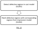
- a three-dimensional scanning method comprising:
- One of the first point cloud and second point cloud may be a point cloud of a dental impression, and the other of the first point cloud and second point cloud may be a point cloud of a cast from the dental impression.
- the method may comprise surfacing the first point cloud, and uniformly sampling the surfaced model to generate a uniformly sampled point cloud.
- the method may comprise:
- the method may comprise inverting the second point cloud and aligning it with the first point cloud.
- the method may comprise determining a closest point in the uniformly sampled point cloud for each point in the inverted and aligned point cloud of the impression point cloud.
- the method may comprise, in response to the determined closest point being a point flagged for replacement, adding the point to a temporary point cloud.
- the method may comprise editing the temporary point cloud to include neighbouring points of the second point cloud.
- the method may comprise clustering the temporary point cloud to form a plurality of patches.
- the method may comprise aligning each patch to the first point cloud.
- the method of the third aspect may be executable by the three-dimensional (3D) dental scanning system of the first aspect.
- a computer-readable storage medium comprising instructions, which when executed by a computer, cause the computer to carry out any of the methods defined herein.
- the computer-readable storage medium may be tangible and/or non-transient.
- a computer program product comprising instructions, which when the program is executed by a computer, cause the computer to carry out any of the methods defined herein.
- the invention also extends to a computer device having a memory and a processor configured to perform any of the methods disclosed herein.
- examples of the disclosure provide a 3D dental scanner for scanning a dental object, wherein the scanner provides 5 axes of relative motion between the dental object and the scanning section, whilst retaining the dental object in a substantially horizontal plane.
- the scanner provides 5 axes of relative motion between the dental object and the scanning section, whilst retaining the dental object in a substantially horizontal plane.
- FIG 1-6 show a 3D dental scanning system 1 in accordance with an example of the disclosure.
- the dental scanning system 1 comprises a scanning apparatus 100 and a controlling device 200.
- the scanning apparatus 100 is shown in detail in FIG. 2-5 .
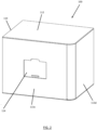
- the scanning apparatus 100 comprises an enclosure 110, which retains and supports the other components of the scanning apparatus 100.
- the enclosure 110 takes the form of a substantially cuboid housing, having a bottom wall 111, top wall 112 and four substantially vertical sidewalls 113a-d.
- a front wall 113a of the sidewalls 113 comprises a door 114 to access the interior of the enclosure 110.
- the door 114 may be a sliding door.
- the dimensions of the enclosure 110 may be approximately 440mm in height between bottom wall 111 and top wall 112, approximately 580mm between walls 113b and 113d, and approximately 450mm between walls 113a and 113c. These dimensions allow the scanning apparatus 100 to be placed on a desktop or work surface, for example in a dental surgery.
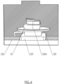
- the scanning apparatus 100 comprises a motion section 120.
- the motion section 120 may comprise a plurality of actuators.
- the motion section 120 comprises a first linear actuator 121.
- the first linear actuator 121 is mounted on the bottom wall 111, and is configured for motion in a first horizontal direction, hereinafter referred to as the X direction.
- the motion section 120 also comprises a second linear actuator 122, which is mounted on the first linear actuator 121. Accordingly, the first linear actuator 121 is configured to translate the second linear actuator 122 in the X direction.
- a plate support element 123 is mounted on the second linear actuator 122.
- the plate support element 123 is configured to support a plate 124, which can be best seen in FIG. 6 .
- the plate 124 defines a scanning surface 124a upon which a dental object D can be placed.
- the plate 124 may take the form of a substantially planar surface, which is circular in plan view and which is disposed in a substantially horizontal plane.
- the scanning surface 124a comprises a high-friction surface.
- a non-slip mat may be disposed on the scanning surface 124a.
- the high-friction surface may for example comprise ridges, bumps or other projections that increase the friction between the surface 124a and the dental object D placed thereon. Accordingly, the dental object D remains in position on the scanning surface 124a during motion of the surface 124.
- control unit 140 and storage 150 may be comprised in a mini-PC 141.
- the control unit 140 and storage may also be comprised in a microcontroller (e.g. an iOS ® ).
- the mini-PC 141 may control the scanning section 130, as well as sending control instructions to the microcontroller, which in turn controls motion of the motion section 130.
- a 3D point cloud is derived, according to a structured light scanning technique. It will be appreciated that part of the process of deriving the 3D point cloud from the captured images may be carried out by the controller 140, with further processing carried out by the controller 210.
- the motion section 120 and scanning section 130 may be moved relative to each other in 5 axes of motion.
- This allows the scanning section 130 to capture scans from a very wide range of positions, therefore providing a wide-coverage scan with high detail.
- the scans can be captured without requiring clamping or other securement of the dental object D to the plate 124.
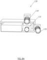
- the scanning section 1130 is also configured to operate in a second mode, which may be referred to herein as a vertical mode, in which camera 1133 and projector 1131 are used in scanning. Accordingly, the second camera 1133 and the projector 1131 form a stereo pair with a vertical baseline extending therebetween.
- the projector 1131 may project structured light patterns (e.g. a series of lines) that are orthogonal to the vertical baseline.
- the scanning section 1130 is one example configuration in which a first notional line connecting the first camera 1132 and projector 1131 and a second notional line connecting the second camera 1133 and projector 1131 are non-colinear.
- the first and second notional line are orthogonal, with the first notional line being substantially horizontal.
- the scanning section may be configured in other ways in which the first and second notional lines are non-colinear.
- the angle between the lines may be acute or obtuse.
- the notional lines need not coincide with the horizontal and/or vertical planes.
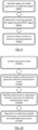
- FIG. 9 is a flowchart of an example scanning method.
- the scanning method generates a sequence of scan locations, so as to provide a high-coverage scan of the dental object.
- step S901 an input point cloud of a dental object is analysed, and a region of the object that is scanned at detail level below a predetermined sufficient detail level is identified.
- step S902 a scanning position for capturing the identified region is determined.
- step S903 the motion section 120 and scanning section 130 are moved to the scanning position to capture the identified region.
- FIG. 10 illustrates the process of step S901 in more detail.
- a first step S1001 the input point cloud is surfaced. This is the process of re-constructing the 3D surface of the dental object based on the points in the point cloud. For example, a Poisson surfacing algorithm is used to generate a surface from the 3D model. This results in a surfaced mesh.
- step S1002 the surfaced mesh is sampled at a uniform distance, so as to generate a uniformly sampled point cloud.
- the sampling distance is 0.5mm. The distance may be varied, with smaller distances increasing accuracy at the expense of processing speed.
- step S1003 for each point in the uniformly sampled point cloud, a closest point in the input point cloud is identified.
- step S1004 if the distance between the point in the uniformly sampled point cloud and the identified closest point exceeds a threshold distance, it is indicative that this region of the input point cloud has been captured in insufficient detail.
- Each point that exceeds the threshold is flagged, for example by altering the colour of the point.
- the threshold may for example be 0.3mm, though in a similar manner to the sampling distance, smaller or larger distances may be employed.
- the point may then be removed from the uniformly sampled point cloud.
- Such large distances may be indicative of a region of the uniformly sampled point cloud where the surfacing of the model is inaccurate, and therefore should not be used.
- the dental model may comprise unscannable regions, for example with black or highly reflective parts.
- the areas of the uniformly sampled point cloud which correspond to an unscannable region will not have proximate corresponding points in the input point cloud. Accordingly, to avoid repeatedly attempting to scan an unscannable region, a list is maintained of every previous scan location from which a scan of the dental object has already been obtained. A ray-cast is run from each of these previous scan locations to see if a previous view should have captured the unseen point already. If the ray-cast indicates that the unseen point was visible from a previous scan location, it may be determined that the point is an unscannable point.
- a point may be determined to be unscannable when there exist a predetermined number of previous views (e.g. 2) that should have captured the point, but did not. This avoids discarding points that are unscannable due to an anomalous reflection in one view only.
- FIG. 11 illustrates the process of step S902 in more detail.
- a first step S1101 for a given flagged point, an optimal viewing position is determined.
- the optimal viewing point is determined by first projecting a normal line from the flagged point.
- the normal line is a line perpendicular to a plane tangential to the flagged point.
- a point on the normal line that is at a distance from the flagged point corresponding to the optimal focal distance of the scanning section 130,1130 is then determined to be the optimal viewing position for the flagged point.
- a second step S1102 the optimal viewing position is verified to ensure the flagged point will not be occluded when viewed from the cameras of the scanning section 130, 1130.
- the scanning section is virtually positioned at the optimal viewing position, and a ray-cast is carried out from the virtual position of the centres of the cameras to the flagged point.
- this camera position is stored in a list of candidate scanning section positions (S1103).
- the scanning section 1130 may operate in one of a plurality of modes, in which one or more cameras and the projector are in operation. Accordingly, in one example, a clear line-of-sight from all of the cameras that are in use in the current scanning mode is required. In further examples, if a clear line-of-sight is available in one of the scanning modes, the camera position is stored, along with a record of the mode in which the clear line-of-sight is available. Accordingly, the scanning method may automatically select the most appropriate scanning mode for capturing a particular point. In some examples, a predetermined ranking may be defined, such that the best available scanning mode is used. For example, the method may select the trifocal or diagonal modes if both cameras and the projector have a clear line-of-sight, with the horizontal and vertical modes acting as fall-backs.
- the angle of the normal line is iteratively adjusted.
- the angle of the normal line is adjusted by 1 degree in one axis at a time, until a position is arrived at in which the line of sight is clear (S1104).
- a conical pattern is traced, with the point at the peak of the cone and the position of the camera forming the base of the cone.
- the radius of the base of the cone may be progressively increased, until a position with clear line of sight is found.
- the method therefore effectively combines a brute-force search with optimisation based on the ideal position.
- the ranking is such that a particular flagged point may not be repeatedly counted once it has appeared in a particular scan. That is to say, a point already appearing in one scan position does not then subsequently contribute to the count of points visible in other lower-ranking scan positions.
- dental impressions are a negative imprint of a patient's inter-oral structures, from which a dental model may be cast. Scanning a cast dental model may result in missing crucial areas of detail which may be more readily visible in the dental impression. For example, areas of detail in the interproximal regions and the retracted gingival sulcus around a crown preparation may not be captured accurately. Conversely, regions which may be difficult to accurately scan in a dental impression may be more readily visible in the cast model.
Landscapes
- Health & Medical Sciences (AREA)
- Life Sciences & Earth Sciences (AREA)
- Engineering & Computer Science (AREA)
- Physics & Mathematics (AREA)
- General Health & Medical Sciences (AREA)
- Public Health (AREA)
- Animal Behavior & Ethology (AREA)
- Veterinary Medicine (AREA)
- Dentistry (AREA)
- Oral & Maxillofacial Surgery (AREA)
- Optics & Photonics (AREA)
- Epidemiology (AREA)
- Surgery (AREA)
- Computer Vision & Pattern Recognition (AREA)
- General Physics & Mathematics (AREA)
- Medical Informatics (AREA)
- Biophysics (AREA)
- Biomedical Technology (AREA)
- Heart & Thoracic Surgery (AREA)
- Molecular Biology (AREA)
- Pathology (AREA)
- Theoretical Computer Science (AREA)
- Radiology & Medical Imaging (AREA)
- Nuclear Medicine, Radiotherapy & Molecular Imaging (AREA)
- Audiology, Speech & Language Pathology (AREA)
- Water Supply & Treatment (AREA)
- Quality & Reliability (AREA)
- Dental Tools And Instruments Or Auxiliary Dental Instruments (AREA)
- Length Measuring Devices By Optical Means (AREA)
- Image Analysis (AREA)
- Apparatus For Radiation Diagnosis (AREA)
Claims (5)
- Dreidimensionales Scanverfahren, das Folgendes umfasst:Identifizieren eines Gebiets zum Ersetzen in einer ersten Punktwolke eines Dentalobjekts (D);Ausbessern des Gebiets zum Ersetzen mit einem entsprechenden Gebiet aus einer zweiten Punktwolke eines Dentalobjekts (D);gekennzeichnet durch Rekonstruieren der Oberfläche (S1002) der ersten Punktwolke und gleichmäßiges Abtasten des Oberflächenmodells, um eine gleichmäßig abgetastete Punktwolke zu generieren,Identifizieren (S1003) eines nächstliegenden Punkts in der ersten Punktwolke zu jedem Punkt in der gleichmäßig abgetasteten Punktwolke; undKennzeichnen (S1004) des Punkts in der gleichmäßig abgetasteten Punktwolke zum Ersetzen, wenn ein Abstand zwischen dem Punkt in der gleichmäßig abgetasteten Punktwolke und dem identifizierten nächstliegenden Punkt einen Schwellenabstand überschreitet.
- Verfahren nach Anspruch 1, wobei eine der ersten Punktwolke und der zweiten Punktwolke eine Punktwolke einer Abformung ist und die andere der ersten Punktwolke und der zweiten Punktwolke eine Punktwolke eines Abgusses der Abformung ist.
- Verfahren nach Anspruch 1, umfassend:Invertieren der zweiten Punktwolke und Ausrichten derselben mit der ersten Punktwolke;Bestimmen eines nächstliegenden Punkts in der gleichmäßig abgetasteten Punktwolke für jeden Punkt in der invertierten und ausgerichteten Punktwolke der zweiten Punktwolke;als Reaktion darauf, dass der bestimmte nächstliegende Punkt ein zum Ersetzen gekennzeichneter Punkt ist, Hinzufügen des Punkts zu einer temporären Punktwolke.
- Verfahren nach Anspruch 3, umfassend:
Bearbeiten der temporären Punktwolke, um benachbarte Punkte der zweiten Punktwolke einzuschließen. - Verfahren nach Anspruch 4, umfassend:Clustern der temporären Punktwolke, um mehrere Patches zu bilden, undAusrichten jedes Patches mit der ersten Punktwolke.
Applications Claiming Priority (3)
| Application Number | Priority Date | Filing Date | Title |
|---|---|---|---|
| GB201913469A GB201913469D0 (en) | 2019-09-18 | 2019-09-18 | Three-dimensional dental scanning system and method of scanning |
| EP20780295.0A EP4031060B8 (de) | 2019-09-18 | 2020-09-17 | Dreidimensionales zahnärztliches scansystem und scanverfahren |
| PCT/GB2020/052255 WO2021053338A1 (en) | 2019-09-18 | 2020-09-17 | Three-dimensional dental scanning system and method of scanning |
Related Parent Applications (2)
| Application Number | Title | Priority Date | Filing Date |
|---|---|---|---|
| EP20780295.0A Division EP4031060B8 (de) | 2019-09-18 | 2020-09-17 | Dreidimensionales zahnärztliches scansystem und scanverfahren |
| EP20780295.0A Division-Into EP4031060B8 (de) | 2019-09-18 | 2020-09-17 | Dreidimensionales zahnärztliches scansystem und scanverfahren |
Publications (4)
| Publication Number | Publication Date |
|---|---|
| EP4357729A2 EP4357729A2 (de) | 2024-04-24 |
| EP4357729A3 EP4357729A3 (de) | 2024-06-26 |
| EP4357729C0 EP4357729C0 (de) | 2025-07-09 |
| EP4357729B1 true EP4357729B1 (de) | 2025-07-09 |
Family
ID=68315433
Family Applications (2)
| Application Number | Title | Priority Date | Filing Date |
|---|---|---|---|
| EP24160434.7A Active EP4357729B1 (de) | 2019-09-18 | 2020-09-17 | Dreidimensionales zahnärztliches abtastverfahren |
| EP20780295.0A Active EP4031060B8 (de) | 2019-09-18 | 2020-09-17 | Dreidimensionales zahnärztliches scansystem und scanverfahren |
Family Applications After (1)
| Application Number | Title | Priority Date | Filing Date |
|---|---|---|---|
| EP20780295.0A Active EP4031060B8 (de) | 2019-09-18 | 2020-09-17 | Dreidimensionales zahnärztliches scansystem und scanverfahren |
Country Status (10)
| Country | Link |
|---|---|
| US (2) | US12082991B2 (de) |
| EP (2) | EP4357729B1 (de) |
| JP (2) | JP7580816B2 (de) |
| KR (1) | KR20220062541A (de) |
| CN (1) | CN114423375B (de) |
| AU (1) | AU2020349647A1 (de) |
| CA (1) | CA3150217A1 (de) |
| ES (1) | ES2984373T3 (de) |
| GB (1) | GB201913469D0 (de) |
| WO (1) | WO2021053338A1 (de) |
Families Citing this family (2)
| Publication number | Priority date | Publication date | Assignee | Title |
|---|---|---|---|---|
| CN113231828B (zh) * | 2021-04-26 | 2022-05-24 | 大连理工大学 | 一种铣磨抛原位成像一体化智能装备及加工方法 |
| KR102875219B1 (ko) * | 2023-02-16 | 2025-10-23 | 주식회사 휴비츠 | 구강 스캔 데이터의 처리 방법 |
Family Cites Families (19)
| Publication number | Priority date | Publication date | Assignee | Title |
|---|---|---|---|---|
| DE3911568A1 (de) | 1989-04-08 | 1990-10-18 | Krupp Medizintechnik | Verfahren und vorrichtung zur ueberpruefung eines zahnaerztlichen abdruckes eines gebisses |
| DE4301538A1 (de) * | 1992-03-17 | 1994-07-28 | Peter Dr Ing Brueckner | Verfahren und Anordnung zur berührungslosen dreidimensionalen Messung, insbesondere zur Messung von Gebißmodellen |
| DE19651909A1 (de) * | 1996-12-13 | 1998-06-18 | Klaus Dipl Ing Schlegelmilch | Verfahren zur Herstellung dreidimensionaler Gebilde |
| US8821158B1 (en) | 1999-10-14 | 2014-09-02 | Geodigm Corporation | Method and apparatus for matching digital three-dimensional dental models with digital three-dimensional cranio-facial CAT scan records |
| JP2002272763A (ja) * | 2001-03-22 | 2002-09-24 | Nikon Gijutsu Kobo:Kk | 歯科補綴物の設計方法及び設計システム |
| DE102004021910A1 (de) * | 2004-05-04 | 2006-02-16 | Michael Schmidt | Einrichtung zur optischen Abtastung eines Objekts, insbesondere eines Zahnmodells |
| US8082120B2 (en) * | 2005-03-11 | 2011-12-20 | Creaform Inc. | Hand-held self-referenced apparatus for three-dimensional scanning |
| EP2312268A1 (de) | 2009-10-16 | 2011-04-20 | Straumann Holding AG | Abtastgerät zum Abtasten von dentalen Objekten und Verfahren zum Abtasten von dentalen Objekten |
| US10105196B2 (en) | 2010-12-22 | 2018-10-23 | 3Shape A/S | Modeling and manufacturing the superstructure for a denture |
| JP6082014B2 (ja) * | 2012-08-28 | 2017-02-15 | 株式会社日立製作所 | 計測システム、計測方法 |
| CA2893035C (en) * | 2012-11-28 | 2019-11-19 | Alfonso Fernandez Pulido | Dental scanner device and related method |
| DE102013203312B4 (de) * | 2013-02-27 | 2016-04-21 | Sirona Dental Systems Gmbh | Extraoraler Dentalscanner |
| WO2014201303A2 (en) * | 2013-06-13 | 2014-12-18 | Edge Toy, Inc. | Three dimensional scanning apparatuses and methods for adjusting three dimensional scanning apparatuses |
| WO2015008820A1 (ja) * | 2013-07-19 | 2015-01-22 | 株式会社ニコン | 形状測定装置、構造物製造システム、形状測定方法、構造物製造方法、形状測定プログラム、及び記録媒体 |
| AT518148A1 (de) * | 2016-01-14 | 2017-07-15 | Heinrich Steger | Verfahren zum Erstellen eines digitalen Gebissmodells |
| AU2017239050A1 (en) * | 2016-03-22 | 2018-10-11 | Novel Technologies Inc. | Systems and methods of facial feature scanning |
| ES2857587T3 (es) * | 2017-02-27 | 2021-09-29 | Kulzer & Co Gmbh | Escáner 3D con sensor giroscópico |
| US10410435B2 (en) | 2017-11-29 | 2019-09-10 | SmileDirectClub LLC | Technologies for merging three-dimensional models of dental impressions |
| US10861250B2 (en) | 2017-11-29 | 2020-12-08 | Sdc U.S. Smilepay Spv | Technologies for merging three-dimensional models of dental impressions |
-
2019
- 2019-09-18 GB GB201913469A patent/GB201913469D0/en not_active Ceased
-
2020
- 2020-09-17 CN CN202080065891.2A patent/CN114423375B/zh active Active
- 2020-09-17 CA CA3150217A patent/CA3150217A1/en active Pending
- 2020-09-17 KR KR1020227010288A patent/KR20220062541A/ko active Pending
- 2020-09-17 US US17/761,349 patent/US12082991B2/en active Active
- 2020-09-17 AU AU2020349647A patent/AU2020349647A1/en active Pending
- 2020-09-17 ES ES20780295T patent/ES2984373T3/es active Active
- 2020-09-17 EP EP24160434.7A patent/EP4357729B1/de active Active
- 2020-09-17 JP JP2022517333A patent/JP7580816B2/ja active Active
- 2020-09-17 WO PCT/GB2020/052255 patent/WO2021053338A1/en not_active Ceased
- 2020-09-17 EP EP20780295.0A patent/EP4031060B8/de active Active
-
2024
- 2024-09-09 US US18/828,635 patent/US20240423763A1/en active Pending
- 2024-10-23 JP JP2024186443A patent/JP7776166B2/ja active Active
Also Published As
| Publication number | Publication date |
|---|---|
| EP4357729A2 (de) | 2024-04-24 |
| AU2020349647A1 (en) | 2022-03-24 |
| JP7776166B2 (ja) | 2025-11-26 |
| EP4357729A3 (de) | 2024-06-26 |
| EP4031060A1 (de) | 2022-07-27 |
| US12082991B2 (en) | 2024-09-10 |
| US20220346920A1 (en) | 2022-11-03 |
| JP2022548682A (ja) | 2022-11-21 |
| EP4031060B1 (de) | 2024-03-06 |
| KR20220062541A (ko) | 2022-05-17 |
| EP4031060B8 (de) | 2024-04-17 |
| CN114423375B (zh) | 2024-10-15 |
| EP4357729C0 (de) | 2025-07-09 |
| GB201913469D0 (en) | 2019-10-30 |
| JP2025003585A (ja) | 2025-01-09 |
| ES2984373T3 (es) | 2024-10-29 |
| WO2021053338A1 (en) | 2021-03-25 |
| JP7580816B2 (ja) | 2024-11-12 |
| CA3150217A1 (en) | 2021-03-25 |
| CN114423375A (zh) | 2022-04-29 |
| US20240423763A1 (en) | 2024-12-26 |
Similar Documents
| Publication | Publication Date | Title |
|---|---|---|
| US20240423763A1 (en) | Three-Dimensional Dental Scanning System and Method of Scanning | |
| KR101358631B1 (ko) | 카메라와 프로젝터가 스테이지 수평 회전축 회전유동부와 결합된 2축 모션부를 갖춘 치과용 데스크탑 3차원 스캐너 | |
| JP6714655B2 (ja) | 口腔外歯科用スキャナ | |
| CA2698525C (en) | Systems and methods for 3d previewing | |
| US8215956B2 (en) | Dental articulator with positioning key | |
| US20120308954A1 (en) | Dental models using stereolithography | |
| CN107861469B (zh) | 一种加工义齿的方法、计算设备和数控机床系统 | |
| CN107205794A (zh) | 数控激光自动化牙体预备方法及装备和牙齿定位器 | |
| CN108056829A (zh) | 一种用于促进牙齿重新定位牙科治疗的方法 | |
| US12295725B2 (en) | Motion adjustment prediction system | |
| Hasanuddin et al. | 3D scanner for orthodontic using triangulation method | |
| KR20220087874A (ko) | 의료영상 정합 방법 및 그 장치 | |
| Nižetić et al. | Calibration of a 5-axis CNC machine for making orthoses by means of a vision system | |
| Santosi et al. | An innovative photogrammetric system for 3D digitization of dental models | |
| CN115550514B (zh) | 数据补偿方法及利用其的数据补偿系统 | |
| CN109655013A (zh) | 基于图像处理的圆锯片锯齿参数检测装置 | |
| EP4193959A1 (de) | System zum erhalt von zuverlässigkeitsdaten mittels mehrwinkelabtastung und verfahren damit | |
| ALEMZAEH et al. | A vision based reverse engineering approach to surface digitizing in restorative dentistry | |
| Alemzadeh et al. | An active vision system for modelling biomaterials |
Legal Events
| Date | Code | Title | Description |
|---|---|---|---|
| PUAI | Public reference made under article 153(3) epc to a published international application that has entered the european phase |
Free format text: ORIGINAL CODE: 0009012 |
|
| STAA | Information on the status of an ep patent application or granted ep patent |
Free format text: STATUS: THE APPLICATION HAS BEEN PUBLISHED |
|
| AC | Divisional application: reference to earlier application |
Ref document number: 4031060 Country of ref document: EP Kind code of ref document: P |
|
| AK | Designated contracting states |
Kind code of ref document: A2 Designated state(s): AL AT BE BG CH CY CZ DE DK EE ES FI FR GB GR HR HU IE IS IT LI LT LU LV MC MK MT NL NO PL PT RO RS SE SI SK SM TR |
|
| PUAL | Search report despatched |
Free format text: ORIGINAL CODE: 0009013 |
|
| AK | Designated contracting states |
Kind code of ref document: A3 Designated state(s): AL AT BE BG CH CY CZ DE DK EE ES FI FR GB GR HR HU IE IS IT LI LT LU LV MC MK MT NL NO PL PT RO RS SE SI SK SM TR |
|
| RIC1 | Information provided on ipc code assigned before grant |
Ipc: G01B 11/00 20060101AFI20240517BHEP |
|
| STAA | Information on the status of an ep patent application or granted ep patent |
Free format text: STATUS: REQUEST FOR EXAMINATION WAS MADE |
|
| 17P | Request for examination filed |
Effective date: 20240930 |
|
| RBV | Designated contracting states (corrected) |
Designated state(s): AL AT BE BG CH CY CZ DE DK EE ES FI FR GB GR HR HU IE IS IT LI LT LU LV MC MK MT NL NO PL PT RO RS SE SI SK SM TR |
|
| GRAP | Despatch of communication of intention to grant a patent |
Free format text: ORIGINAL CODE: EPIDOSNIGR1 |
|
| STAA | Information on the status of an ep patent application or granted ep patent |
Free format text: STATUS: GRANT OF PATENT IS INTENDED |
|
| INTG | Intention to grant announced |
Effective date: 20250210 |
|
| GRAS | Grant fee paid |
Free format text: ORIGINAL CODE: EPIDOSNIGR3 |
|
| GRAA | (expected) grant |
Free format text: ORIGINAL CODE: 0009210 |
|
| STAA | Information on the status of an ep patent application or granted ep patent |
Free format text: STATUS: THE PATENT HAS BEEN GRANTED |
|
| AC | Divisional application: reference to earlier application |
Ref document number: 4031060 Country of ref document: EP Kind code of ref document: P |
|
| AK | Designated contracting states |
Kind code of ref document: B1 Designated state(s): AL AT BE BG CH CY CZ DE DK EE ES FI FR GB GR HR HU IE IS IT LI LT LU LV MC MK MT NL NO PL PT RO RS SE SI SK SM TR |
|
| REG | Reference to a national code |
Ref country code: GB Ref legal event code: FG4D |
|
| REG | Reference to a national code |
Ref country code: CH Ref legal event code: EP |
|
| REG | Reference to a national code |
Ref country code: IE Ref legal event code: FG4D |
|
| REG | Reference to a national code |
Ref country code: DE Ref legal event code: R096 Ref document number: 602020054460 Country of ref document: DE |
|
| U01 | Request for unitary effect filed |
Effective date: 20250801 |
|
| U07 | Unitary effect registered |
Designated state(s): AT BE BG DE DK EE FI FR IT LT LU LV MT NL PT RO SE SI Effective date: 20250812 |
|
| U20 | Renewal fee for the european patent with unitary effect paid |
Year of fee payment: 6 Effective date: 20250812 |
|
| PGFP | Annual fee paid to national office [announced via postgrant information from national office to epo] |
Ref country code: GB Payment date: 20250710 Year of fee payment: 6 |