EP4357581B1 - Rollvorhang und montageverfahren dafür - Google Patents
Rollvorhang und montageverfahren dafür Download PDFInfo
- Publication number
- EP4357581B1 EP4357581B1 EP23159883.0A EP23159883A EP4357581B1 EP 4357581 B1 EP4357581 B1 EP 4357581B1 EP 23159883 A EP23159883 A EP 23159883A EP 4357581 B1 EP4357581 B1 EP 4357581B1
- Authority
- EP
- European Patent Office
- Prior art keywords
- spiral spring
- roller
- shaft
- fixed shaft
- rotatable frame
- Prior art date
- Legal status (The legal status is an assumption and is not a legal conclusion. Google has not performed a legal analysis and makes no representation as to the accuracy of the status listed.)
- Active
Links
Images


Classifications
-
- E—FIXED CONSTRUCTIONS
- E06—DOORS, WINDOWS, SHUTTERS, OR ROLLER BLINDS IN GENERAL; LADDERS
- E06B—FIXED OR MOVABLE CLOSURES FOR OPENINGS IN BUILDINGS, VEHICLES, FENCES OR LIKE ENCLOSURES IN GENERAL, e.g. DOORS, WINDOWS, BLINDS, GATES
- E06B9/00—Screening or protective devices for wall or similar openings, with or without operating or securing mechanisms; Closures of similar construction
- E06B9/24—Screens or other constructions affording protection against light, especially against sunshine; Similar screens for privacy or appearance; Slat blinds
- E06B9/40—Roller blinds
- E06B9/42—Parts or details of roller blinds, e.g. suspension devices, blind boxes
- E06B9/50—Bearings specially adapted therefor
-
- E—FIXED CONSTRUCTIONS
- E06—DOORS, WINDOWS, SHUTTERS, OR ROLLER BLINDS IN GENERAL; LADDERS
- E06B—FIXED OR MOVABLE CLOSURES FOR OPENINGS IN BUILDINGS, VEHICLES, FENCES OR LIKE ENCLOSURES IN GENERAL, e.g. DOORS, WINDOWS, BLINDS, GATES
- E06B9/00—Screening or protective devices for wall or similar openings, with or without operating or securing mechanisms; Closures of similar construction
- E06B9/56—Operating, guiding or securing devices or arrangements for roll-type closures; Spring drums; Tape drums; Counterweighting arrangements therefor
- E06B9/60—Spring drums operated only by closure members
-
- E—FIXED CONSTRUCTIONS
- E06—DOORS, WINDOWS, SHUTTERS, OR ROLLER BLINDS IN GENERAL; LADDERS
- E06B—FIXED OR MOVABLE CLOSURES FOR OPENINGS IN BUILDINGS, VEHICLES, FENCES OR LIKE ENCLOSURES IN GENERAL, e.g. DOORS, WINDOWS, BLINDS, GATES
- E06B9/00—Screening or protective devices for wall or similar openings, with or without operating or securing mechanisms; Closures of similar construction
- E06B9/56—Operating, guiding or securing devices or arrangements for roll-type closures; Spring drums; Tape drums; Counterweighting arrangements therefor
- E06B9/62—Counterweighting arrangements
-
- E—FIXED CONSTRUCTIONS
- E06—DOORS, WINDOWS, SHUTTERS, OR ROLLER BLINDS IN GENERAL; LADDERS
- E06B—FIXED OR MOVABLE CLOSURES FOR OPENINGS IN BUILDINGS, VEHICLES, FENCES OR LIKE ENCLOSURES IN GENERAL, e.g. DOORS, WINDOWS, BLINDS, GATES
- E06B9/00—Screening or protective devices for wall or similar openings, with or without operating or securing mechanisms; Closures of similar construction
- E06B9/56—Operating, guiding or securing devices or arrangements for roll-type closures; Spring drums; Tape drums; Counterweighting arrangements therefor
- E06B9/68—Operating devices or mechanisms, e.g. with electric drive
- E06B9/72—Operating devices or mechanisms, e.g. with electric drive comprising an electric motor positioned inside the roller
-
- E—FIXED CONSTRUCTIONS
- E06—DOORS, WINDOWS, SHUTTERS, OR ROLLER BLINDS IN GENERAL; LADDERS
- E06B—FIXED OR MOVABLE CLOSURES FOR OPENINGS IN BUILDINGS, VEHICLES, FENCES OR LIKE ENCLOSURES IN GENERAL, e.g. DOORS, WINDOWS, BLINDS, GATES
- E06B9/00—Screening or protective devices for wall or similar openings, with or without operating or securing mechanisms; Closures of similar construction
- E06B9/56—Operating, guiding or securing devices or arrangements for roll-type closures; Spring drums; Tape drums; Counterweighting arrangements therefor
- E06B9/68—Operating devices or mechanisms, e.g. with electric drive
- E06B9/74—Operating devices or mechanisms, e.g. with electric drive adapted for selective electrical or manual operation
-
- E—FIXED CONSTRUCTIONS
- E06—DOORS, WINDOWS, SHUTTERS, OR ROLLER BLINDS IN GENERAL; LADDERS
- E06B—FIXED OR MOVABLE CLOSURES FOR OPENINGS IN BUILDINGS, VEHICLES, FENCES OR LIKE ENCLOSURES IN GENERAL, e.g. DOORS, WINDOWS, BLINDS, GATES
- E06B9/00—Screening or protective devices for wall or similar openings, with or without operating or securing mechanisms; Closures of similar construction
- E06B9/56—Operating, guiding or securing devices or arrangements for roll-type closures; Spring drums; Tape drums; Counterweighting arrangements therefor
- E06B9/78—Operating, guiding or securing devices or arrangements for roll-type closures; Spring drums; Tape drums; Counterweighting arrangements therefor for direct manual operation, e.g. by tassels, by handles
-
- E—FIXED CONSTRUCTIONS
- E06—DOORS, WINDOWS, SHUTTERS, OR ROLLER BLINDS IN GENERAL; LADDERS
- E06B—FIXED OR MOVABLE CLOSURES FOR OPENINGS IN BUILDINGS, VEHICLES, FENCES OR LIKE ENCLOSURES IN GENERAL, e.g. DOORS, WINDOWS, BLINDS, GATES
- E06B9/00—Screening or protective devices for wall or similar openings, with or without operating or securing mechanisms; Closures of similar construction
- E06B9/56—Operating, guiding or securing devices or arrangements for roll-type closures; Spring drums; Tape drums; Counterweighting arrangements therefor
- E06B9/80—Safety measures against dropping or unauthorised opening; Braking or immobilising devices; Devices for limiting unrolling
- E06B9/82—Safety measures against dropping or unauthorised opening; Braking or immobilising devices; Devices for limiting unrolling automatic
- E06B9/90—Safety measures against dropping or unauthorised opening; Braking or immobilising devices; Devices for limiting unrolling automatic for immobilising the closure member in various chosen positions
Definitions
- the present application relates to a field of cordless curtain and, in particular, relates to a rolling curtain and an assembling method thereof.
- an electric curtain is a popular and commonly used intelligent furniture, which adopts different control manners, such as remote controller, wire control, and voice control. It can be also closed at a set timing.
- Existing electric curtains are generally driven by a motor with reducer. However, they cannot be opened or closed by hand if there is a power cut, which may significantly influence the user experience.
- a force balance assembly adopts a variable-force spiral spring.
- a torque force of the spiral spring and the gravity of the curtain cloth are kept at a balance state during the stroke of the curtain, so that the curtain can hover at any position.
- US 2013/220560 A1 a motorized roller curtain is described using a spiral spring device mounted inside of a second end of the roller and having a fixed shaft. It further contains a rotation stop notch provided on the outer rotatable frame, whereby the outer rotatable frame is synchronously rotated with the roller. It traditionally describes two fixed brackets configured for fixing the spiral spring device and the motor respectively. It is required only a small outer force to break the force balance, and lift the curtain by pushing or pulling, which provides an excellent experience for user.
- the present application provides a rolling curtain and an assembling method thereof.
- the present application provides a havoring-type rolling curtain.
- a rolling curtain provided in the present application adopts the following technical solution.
- a rolling curtain includes:
- a first stop plate is provided on the first fixed bracket, a first stop groove is provided on an outer end of the fixed shaft, the first stop plate is inserted in the first stop groove, a second stop plate is provided on the second fixed bracket, a second stop groove is provided on an outer end of the motor, and the second stop plate is inserted in the second stop groove.
- a first stop plate is provided on the first fixed bracket, and a second stop plate is provided on the second fixed bracket in the present application to prevent the fixed shaft and the motor from being rotated.
- the first stop plate and the second stop plate also have a role of supporting, which can support the whole rolling curtain.
- a bearing is sleeved on a housing of the motor, the bearing matches with the inner wall of the roller, a driving plate is provided on a motor shaft of the motor, and the driving plate is interfered with the stop strip so that the driving plate drives the roller to rotate.
- a through hole is provided on an inner end of the spiral spring
- a mounting plane is provided at a corresponding position on the fixed shaft
- a screw hole is provided on the mounting plane
- the inner end of the spiral spring is fixedly connected to the mounting plane of the fixed shaft by screw
- a hook is provided on an outer end of the spiral spring
- a traverse rod is provided on the outer rotatable frame, and the hook is hooked on the traverse rod.
- the outer contour of the fixed shaft is an arc surface, which is not easy to mount the inner end of the spiral spring, so that the spiral spring is unstable and easily to be dissembled.
- a mounting plane (where the section of the fixed shaft has a D-shape) is provided on the fixed shaft, the inner end of the spiral spring has a certain radian, which could be understood as an elastic gasket, so that the inner end of the spiral spring can be well and stably fixed after locking by a screw.
- the spiral spring device further includes an auxiliary spiral spring, an auxiliary shaft and a key, two ends of the auxiliary shaft are rotatably provided in the shaft holes of two adjacent vertical partition plates respectively, the auxiliary spiral spring with one end fixed connected to the auxiliary shaft and the other end fixedly connected to the outer rotatable frame is sleeved on the auxiliary shaft, key holes are provided on centers of the fixed shaft and the auxiliary shaft, the key is inserted in the key hole of the auxiliary shaft from the keyhole of the fixed shaft, so that the fixed shaft and the auxiliary shaft are synchronously rotated.
- an auxiliary spiral spring and an auxiliary shaft are provided in the present application in order to avoid this condition.
- the key is preferably inserted in the key hole of the auxiliary shaft, so that the fixed shaft and the auxiliary shaft are synchronously rotated, which can be regarded as one shaft.
- the auxiliary spiral spring has the same effect as the other spiral springs.
- the key can be taken out when the torque force of the spiral spring is too large in the adjusting process, so that the auxiliary shaft won't be synchronously rotated with the fixed shaft, which is equivalent that the auxiliary spiral spring is disused, having no function.
- the torque force of the spiral spring device and the gravity of the curtain cloth can under a balance. It is easy to adjust since the spiral spring device is not necessary to be disassembled.
- the auxiliary spiral spring has a same torsion variation curvature as that of the spiral spring, the torque force of the auxiliary spiral spring is smaller than that of the spiral spring in the same position.
- the spiral spring device further includes a plurality of auxiliary spiral springs and a plurality of auxiliary shafts, and the plurality of auxiliary shafts are coaxial arranged.
- a plurality of auxiliary spiral springs are provided, and each of the auxiliary spiral springs can be used or disused, so as to enlarge the adjusting range of torque force of the spiral spring device, satisfying various demands of customers.
- the key holes and the key all have rectangular sections.
- the rectangular key has a better transmission effect.
- a plurality of reserved holes for dodging the screws are provided on the key, and the reserved holes have an oblong shape.
- the key in the present application needs to be moved back and forth, so a plurality of reserved holes for allowing the screws to move are provided on the key, the reserved holes have an oblong shape, so as to be moved back and forth in a certain range.
- the inner wall of the roller is a rough surface, configured for increasing the friction force between the spiral spring and the inner wall of the roller.
- the spiral spring is loosened in the roller to abut against the inner wall of the roller.
- the inner wall of the roller in the present application is designed as a rough surface to increase the friction force between the spiral spring and the inner wall of the roller, prevent the axial movement of the spiral spring device in the interior of the roller when the spiral spring is tightened.
- An assembling method of the above hovering rolling curtain includes the following steps:
- the assembling method in the present application can realize the assembling of the spiral spring at retailers or customers, which is convenient for assembling on site.
- the torque force of the spiral spring device can be adjusted in a certain range to satisfy the demands of different sizes and different materials of the curtain cloth for customers, further to meet the demand of highly customization, which is expected to expand the market size.
- the hovering rolling curtain in the present application could realize a control by both manual and automatic operations.
- the curtain can be manually closed when there is a power cut or a remote controller is not available, improving use experience for a user.
- the spiral spring device in the present application is newly designed, so as to be assembled at retailers and even by the customers themselves.
- the torque force of the spiral spring device can be adjusted in a certain range to satisfy the demand of different curtain cloth sizes and different curtain cloth materials for customers, further to meet the demand of highly customization, which is expected to expand the market size.
- a bearing is provided between the motor and the inner wall of the roller in the present application, extremely reducing the friction force at this position.
- the rolling curtains produced by different batches have little difference, which is not easy to influence the balance condition of the hovering rolling curtain.
- Listing of reference signs 10 roller; 11 stop strip; 12 curtain cloth groove; 20 curtain cloth; 21 snap-in strip; 30 lower rod; 40 motor; 41 second stop groove; 42 bearing; 43 driving plate; 50 spiral spring device; 51 fixed shaft; 511 pin hole; 512 first stop groove; 513 mounting plane; 514 screw hole; 515 screw; 516 key hole; 52 outer rotatable frame; 521 shaft hole; 522 rotation stop notch; 523 pin hole; 524 traverse rod; 525 vertical partition plate; 53 spiral spring; 531 through hole; 532 hook; 54 inserting pin; 55 auxiliary spiral spring; 56 auxiliary shaft; 564 key hole; 57 key; 571 reserved hole; 60 first fixed bracket; 61 first stop plate; 70 second fixed bracket; and 71 second stop plate.
- a stroke length of a single spiral spring matches with the length of a curtain cloth, while a torsion curve of single spiral spring is not to be directly related to the gravity of the curtain cloth, as long as an appropriate number of spiral springs are provided to ensure that the torque force of the spiral spring matches with the gravity of the curtain cloth to realize a balance. Therefore, for a given length of a curtain cloth, a matching spiral spring, as well as an appropriate number thereof, can be chosen based on calculation or experience to match with curtain cloths of different materials and with different widths. The technical solutions of the present application are made based on this principle.
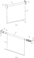
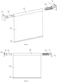
- a rolling curtain disclosed in an embodiment of the present application includes a roller 10, a curtain cloth 20, a lower rod 30, a motor 40, a spiral spring device 50, a first fixed bracket 60 and a second fixed bracket 70.
- a stop strip 11 is provided on an inner wall of the roller 10.
- a semi-opened curtain cloth groove 12 is provided on an outer wall of the roller 10.
- An upper end of the curtain cloth 20 is fixedly connected in the curtain cloth groove 12 of the roller 10 by a snap-in strip 21.
- the lower rod 30 is horizontally arranged on a lower end of the curtain cloth 20.
- the motor 40 is mounted at an inner side of one end of the roller 10 and is configured for driving the roller 10 to rotate, further to lift the curtain cloth 20.
- the spiral spring device 50 is mounted at an inner side of the other end of the roller 10 for providing the hovering force.
- the first fixed bracket 60 and the second fixed bracket 70 are positioned at two ends of the roller 10 respectively and are configured for fixing the spiral spring device 50 and the motor 40 respectively.
- the material of the roller 10 generally adopts cylindrical extruded section bar.
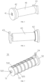
- the spiral spring device 50 includes a fixed shaft 51, an outer rotatable frame 52, a spiral spring 53 and an inserting pin 54.
- a shaft hole 521 is provided on the outer rotatable frame 52.
- the fixed shaft 51 is inserted in the shaft hole 521 of the outer rotatable frame 52.
- the spiral spring 53 is sleeved on the fixed shaft 51, with one end thereof fixedly connected to the fixed shaft 51 and the other end thereof fixedly connected to the outer rotatable frame 52.
- a rotation stop notch 522 is provided on the outer rotatable frame 52. The rotation stop notch 522 is engaged with the stop strip 11 on the roller 10.
- the outer rotatable frame 52 is synchronously rotated with the roller 10.
- Pin holes 511, 523 corresponding to each other are provided on the fixed shaft 51 and the outer rotatable frame 52 respectively.
- the spiral spring 53 is tightly screwed and mounted in the outer rotatable frame 52.
- the inserting pin 54 is inserted in the pin holes 511, 523 of the fixed shaft 51 and the outer rotatable frame 52 for fixedly connecting the fixed shaft 51 to the outer rotatable frame 52.
- a first stop plate 61 is provided on the first fixed bracket 60.
- a first stop groove 512 is provided on an outer end of the fixed shaft 51.
- the first stop plate 61 is inserted in the first stop groove 512.
- a second stop plate 71 is provided on the second fixed bracket 70.
- a second stop groove 41 is provided on an outer end of the motor 40, and the second stop plate 71 is inserted in the second stop groove 41. Since the fixed shaft 51 and the motor 40 themselves cannot be rotated, it is required an outer structure to fix them.
- the first stop plate 61 is provided on the first fixed bracket 60, and the second stop plate 71 is provided on the second fixed bracket 70 in the present application to prevent the fixed shaft 51 and the motor 40 from being rotated.
- the first stop plate 61 and the second stop plate 71 also have a role of supporting, which can support the whole rolling curtain.
- a bearing 42 is sleeved on a housing of the motor 40.
- the bearing 42 is matched with the inner wall of the roller 10.
- a driving plate 43 is provided on a motor shaft of the motor 40.
- the driving plate 43 is interfered with the stop strip 43 so that the driving plate 43 drives the roller 10 to rotate. Since the motor 40 itself cannot be rotated, there is a friction force between the motor 40 and the inner wall of the roller 10. The friction forces are hard to control and differ from each other between different rolling curtains.
- the bearing 42 is provided between the motor 40 and the inner wall of the roller 10 in the present application, extremely reducing the friction force at this position.
- the rolling curtains produced by different batches have little difference, which is not easy to influence the balance condition of the hovering rolling curtain.
- a through hole 531 is provided on an inner end of the spiral spring 53.
- a mounting plane 513 is provided at a corresponding position on the fixed shaft 51.
- a screw hole 514 is provided on the mounting plane 513.
- the inner end of the spiral spring 53 is fixedly connected to the mounting plane 513 of the fixed shaft 51 by screw 515.
- a hook 532 is provided on an outer end of the spiral spring 53.
- a traverse rod 524 is provided on the outer rotatable frame 52. The hook 532 is hooked on the traverse rod 524. Since the outer contour of the fixed shaft 51 is an arc surface, which is not easy to mount the inner end of the spiral spring 53, so that the spiral spring 53 is unstable and easily to be dissembled.
- the mounting plane 513 (where the section of the fixed shaft 51 has a D-shape) is provided on the fixed shaft 51, the inner end of the spiral spring 53 has a certain radian, which could be understood as an elastic gasket, so that the inner end of the spiral spring 53 can be well and stably fixed after locking by screw 515.
- the inner wall of the roller 10 is rough surface, which is configured for increasing the friction force between the spiral spring 53 and the inner wall of the roller 10.
- the spiral spring 53 is loosened to abut against the inner wall of the roller 10.
- the inner wall of the roller 10 in the present application is designed as a rough surface to increase the friction force between the spiral spring 53 and the inner wall of the roller 10, prevent the axial movement of the spiral spring device 50 in the interior of the roller 10 when the spiral spring 53 is tightened.
- the assembling method of the above hovering rolling curtain includes the following steps:
- the detail sequency of the steps is not limited in the present application, some steps can be exchanged, for example, there is no difference whether mounting the motor 40 firstly or mounting the spiral spring device 50 firstly, which are both feasible.
- Embodiment 1 The spiral spring device 50 in the Embodiment 1 is required to be disassembled repeatedly, and the adjusting is also a tedious operation.
- Embodiment 2 is provided in the present application in order to prevent this situation.
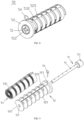
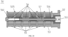
- the spiral spring device 50 further includes an auxiliary spiral spring 55, an auxiliary shaft 56 and a key 57.
- Two ends of the auxiliary shaft 56 are rotatably provided in the shaft holes 521 of two adjacent vertical partition plates 525 respectively.
- the auxiliary spiral spring 55 with one end fixed connected to the auxiliary shaft 56 and the other end fixedly connected to the outer rotatable frame 52 is sleeved on the auxiliary shaft 56.
- Key holes 516, 561 are provided both on centers of the fixed shaft 51 and the auxiliary shaft 56.
- the key 57 is inserted in the key hole 561 of the auxiliary shaft 56 from the keyhole 516 of the fixed shaft 51, so that the fixed shaft 51 and the auxiliary shaft 56 are synchronously rotated.
- the auxiliary spiral spring 55 has a same torsion variation curvature with that of the spiral spring 53, the torque force of the auxiliary spiral spring 55 is smaller that of the spiral spring 53 in the same position. Since the torque force of the auxiliary spiral spring 55 is an additional variable, which is a key factor for adjusting the torque force. If the torsion value of the auxiliary spiral spring 55 is relatively large, it cannot play a role of adjusting. Therefore, the torque force of the auxiliary spiral spring 55 in the present application is reduced. Under the same processing technology, the width of the auxiliary spiral spring 5 is designed to be smaller than the width of the spiral spring 53.
- the curtain cloth 20 is pushed to lift when the target pulling force of the hovering rolling curtain reaches 0.3 KG (it is required to against the friction of the system and the resistance of the motor), and it is better to provide a tolerance of 0.3 KG by the torque force of the auxiliary spiral spring 55.
- the key holes 516, 561 and the key 57 all have rectangular sections.
- the rectangular key 57 has a better transmission effect.
- a plurality of reserved holes 571 for dodging the screws 515 are provided on the key 57, and the reserved holes 571 have an oblong shape.
- the key 57 in the present application needs to be moved back and forth, so a plurality of reserved holes 571 for dodging the screws 515 are provided on the key 57, the reserved holes 571 have an oblong shape, so as to be moved back and forth in a certain range.
- the reserved holes 571 can also be omitted.
- the implementation principle of this embodiment is that: the auxiliary spiral spring 55 and the auxiliary shaft 56 are provided in the present application.
- the key 57 is preferably inserted in the key holes 516, 561 of the auxiliary shaft 56, so that the fixed shaft 51 and the auxiliary shaft 56 are synchronously rotated, which can be regarded as one shaft.
- the auxiliary spiral spring 55 has the same effect as the other spiral springs 53.
- the key 57 can be taken out when the torque force of the spiral spring device 50 is too large in the adjusting process, so that the auxiliary shaft 56 won't be synchronously rotated with the fixed shaft 51, which is equivalent that the auxiliary spiral spring 55 is disused, having no function.
- the torque force of the spiral spring device 50 and the gravity of the curtain cloth 20 can reach a balance. It is easy to adjust since the spiral spring device 50 is not necessary to be disassembled.
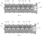
- the spiral spring device 50 includes a plurality of auxiliary spiral springs 55 and a plurality of auxiliary shafts 56, and the plurality of auxiliary shafts 56 are coaxial arranged.
- the detail amount thereof is five.
- the plurality of auxiliary spiral springs 55 are provided, each auxiliary spiral spring 55 can be used or disused, so as to enlarge the adjusting range of torque force of the spiral spring device 50, satisfying changeable demands of customers, it becomes a universal spiral spring device 50 in theory.
- the detail realizing method is inserting keys 57 with different lengths, for example, some of the keys 57 only drive one auxiliary shaft 56 (referring to FIG.19 ), some of the keys 57 can drive four auxiliary shafts 56 (referring to FIG.20 ), and so on.
Landscapes
- Engineering & Computer Science (AREA)
- Structural Engineering (AREA)
- Architecture (AREA)
- Civil Engineering (AREA)
- Curtains And Furnishings For Windows Or Doors (AREA)
- Operating, Guiding And Securing Of Roll- Type Closing Members (AREA)
Claims (11)
- Rollvorhang, dadurch gekennzeichnet, dass er umfasst:eine Walze (10), wobei an einer Innenwand der Walze (10) ein Anschlagstreifen (11) und an einer Außenwand der Walze (10) eine halboffene Vorhangtuchrille (12) vorgesehen ist;ein Vorhangtuch (20), wobei ein oberes Ende des Vorhangtuchs (20) fest in der Vorhangtuchrille (12) angebracht ist;einen Motor (40), der an einer Innenseite eines ersten Endes der Walze (10) angebracht und so konfiguriert ist, dass er die Walze (10) antreibt, damit sie sich dreht, um das Vorhangtuch (20) anzuheben;eine Spiralfedervorrichtung (50), die an einer Innenseite eines zweiten Endes der Walze (10) angebracht ist und eine feste Welle (51), einen äußeren drehbaren Rahmen (52), eine Mehrzahl von Spiralfedern (53) und einen Einsetzstift (54) umfasst, wobei ein Wellenloch (521) an dem äußeren drehbaren Rahmen (52) vorgesehen ist, die feste Welle (51) in das Wellenloch (521) des äußeren drehbaren Rahmens (52) eingesetzt ist, die Mehrzahl der Spiralfedern (53) auf der festen Welle (51) Seite an Seite aufgewickelt sind, wobei eine Mehrzahl von vertikalen Trennplatten (525) zum Trennen benachbarter Spiralfedern (53) an dem äußeren drehbaren Rahmen (52) vorgesehen sind, wobei ein erstes Ende der Spiralfeder (53) fest mit der festen Welle (51) und ein zweites Ende der Spiralfeder (53) fest mit dem äußeren drehbaren Rahmen (52) verbunden ist, wobei eine Drehstoppkerbe (522) an dem äußeren drehbaren Rahmen (52) vorgesehen ist, wobei die Drehstoppkerbe (522) mit dem Anschlagstreifen (11) an der Walze (10) in Eingriff steht, wobei der äußere drehbare Rahmen (52) synchron mit der Walze (10) gedreht wird, einander entsprechende Stiftlöcher (511, 523) an der festen Welle (51) bzw. dem äußeren drehbaren Rahmen (52) vorgesehen sind, wobei die Spiralfeder (53) in dem äußeren drehbaren Rahmen (52) montiert ist, und der Einsetzstift (54) in die Stiftlöcher (511, 523) der festen Welle (51) und des äußeren drehbaren Rahmens (52) eingesetzt ist, um die feste Welle (51) fest mit dem äußeren drehbaren Rahmen (52) zu verbinden; und umfassend eine erste feste Halterung (60) und eine zweite feste Halterung (70), die jeweils an zwei Enden der Walze (10) angeordnet sind und für die Befestigung der Spiralfedervorrichtung (50) bzw. des Motors (40) konfiguriert sind.
- Rollvorhang nach Anspruch 1, dadurch gekennzeichnet, dass eine erste Anschlagplatte (61) an der ersten festen Halterung (60) vorgesehen ist, dass eine erste Anschlagnut (512) an einem äußeren Ende der festen Welle (51) vorgesehen ist, dass die erste Anschlagplatte (61) in die erste Anschlagnut (512) eingesetzt ist, dass eine zweite Anschlagplatte (71) an der zweiten festen Halterung (70) vorgesehen ist, dass eine zweite Anschlagnut (41) an einem Ende des Motors (40) vorgesehen ist, und dass die zweite Anschlagplatte (71) in die zweite Anschlagnut (41) eingesetzt ist.
- Rollvorhang nach Anspruch 1 oder Anspruch 2, dadurch gekennzeichnet, dass ein Lager (42) auf ein Gehäuse des Motors (40) aufgeschoben ist, wobei das Lager (42) mit der Innenwand der Walze (10) zusammenpasst, wobei eine Antriebsplatte (43) auf einer Motorwelle des Motors (40) vorgesehen ist und die Antriebsplatte (43) mit dem Anschlagstreifen (11) zusammenwirkt, so dass die Antriebsplatte (43) die Walze (10) zum Drehen antreibt.
- Rollvorhang nach einem der Ansprüche 1 bis 3, dadurch gekennzeichnet, dass ein Durchgangsloch (531) an einem inneren Ende der Spiralfeder (53) vorgesehen ist, eine Montageebene (513) an der festen Welle (51) vorgesehen ist, ein Schraubenloch (514) an der Montageebene (513) vorgesehen ist, das innere Ende der Spiralfeder (53) fest mit der Montageebene (513) der festen Welle (51) durch eine Schraube (515) verbunden ist, ein Haken (532) an einem äußeren Ende der Spiralfeder (53) vorgesehen ist, eine Traversenstange (524) an dem äußeren drehbaren Rahmen (52) vorgesehen ist und der Haken (532) an der Traversenstange (524) eingehakt ist.
- Rollvorhang nach einem der Ansprüche 1 bis 4, dadurch gekennzeichnet, dass die Spiralfedervorrichtung (50) ferner eine Hilfsspiralfeder (55), eine Hilfswelle (56) und einen Keil (57) umfasst, wobei zwei Enden der Hilfswelle (56) drehbar in den Wellenlöchern (521) von zwei benachbarten vertikalen Trennplatten (525) vorgesehen sind, die Hilfsspiralfeder (55) mit einem ersten Ende, das fest mit der Hilfswelle (56) verbunden ist, und einem zweiten Ende, das fest mit dem äußeren drehbaren Rahmen (52) verbunden ist, auf die Hilfswelle (56) gesteckt ist, Passfederlöcher (516, 561) sind in der Mitte der festen Welle (51) und der Hilfswelle (56) vorgesehen, und die Passfeder (57) wird in das Passfederloch (561) der Hilfswelle (56) vom Passfederloch (516) der festen Welle (51) aus eingeführt, so dass die feste Welle (51) und die Hilfswelle (56) synchron gedreht werden.
- Rollvorhang nach Anspruch 5, dadurch gekennzeichnet, dass die Hilfsspiralfeder (55) die gleiche Torsionsänderungskrümmung wie die Spiralfeder (53) aufweist und die Drehmomentkraft der Hilfsspiralfeder (55) kleiner ist als die der Spiralfeder (53) in der gleichen Position.
- Rollvorhang nach Anspruch 5 oder Anspruch 6, dadurch gekennzeichnet, dass in dem Schlüssel (57) eine Mehrzahl von Langlöchern vorgesehen ist.
- Rollvorhang nach einem der Ansprüche 5 bis 7, dadurch gekennzeichnet, dass die Schlüssellöcher (516, 561) und der Schlüssel (57) rechteckige Querschnitte aufweisen.
- Rollvorhang nach einem der Ansprüche 5 bis 8, dadurch gekennzeichnet, dass die Spiralfedervorrichtung (50) ferner eine Mehrzahl von Hilfsspiralfedern (55) und eine Mehrzahl von Hilfswellen (56) umfasst, wobei die Mehrzahl von Hilfswellen (56) koaxial angeordnet ist.
- Rollvorhang nach einem der Ansprüche 1 bis 9, dadurch gekennzeichnet, dass die Innenwand der Walze (10) eine raue Oberfläche aufweist.
- Verfahren zum Zusammenbau des Rollvorhangs nach einem der Ansprüche 1 bis 10, dadurch gekennzeichnet, dass es die folgenden Schritte umfasst:Anbringen eines Endes des Vorhangtuchs (20) an der Walze (10);vollständiges Aufwickeln des Vorhangtuchs (20) auf die Walze (10);Zusammenbau der Spiralfedervorrichtung (50), wobei die feste Welle (51) in das Wellenloch (521) des äußeren drehbaren Rahmens (52) eingesetzt ist, ein Ende der Spiralfeder (53) fest mit der festen Welle (51) verbunden wird, so dass die feste Welle (51) relativ zum äußeren drehbaren Rahmen (52) gedreht wird, die Spiralfeder (53) festgezogen wird, das andere Ende der Spiralfeder (53) fest mit dem äußeren drehbaren Rahmen (52) verbunden wird, die Stiftlöcher (511, 523) der festen Welle (51) und des äußeren drehbaren Rahmens (52) aufeinander ausgerichtet werden und der Einsetzstift (54) eingesetzt wird;Einsetzen der zusammengebauten Spiralfedervorrichtung (50) in ein Ende der Walze (10) und Herausnehmen des Einsetzstifts (54), so dass die Spiralfeder (53) abgewickelt wird, um gegen die Innenwand der Walze (10) zu drücken, die feste Welle (51) unter der Wirkung des Drehmoments der Spiralfeder (53) frei gedreht wird und die Spiralfeder (53) sich in einem anfänglichen Betriebszustand befindet; Einsetzen des Motors (40) in das andere Ende der Walze (10);Befestigen der Spiralfedervorrichtung (50) an der ersten festen Halterung (60); und Befestigen des Motors (40) an der zweiten festen Halterung (70).
Applications Claiming Priority (1)
| Application Number | Priority Date | Filing Date | Title |
|---|---|---|---|
| CN202211275214.0A CN117948030A (zh) | 2022-10-18 | 2022-10-18 | 一种手自一体的悬停卷帘及其组装方法 |
Publications (3)
| Publication Number | Publication Date |
|---|---|
| EP4357581A1 EP4357581A1 (de) | 2024-04-24 |
| EP4357581B1 true EP4357581B1 (de) | 2024-12-11 |
| EP4357581C0 EP4357581C0 (de) | 2024-12-11 |
Family
ID=85461601
Family Applications (1)
| Application Number | Title | Priority Date | Filing Date |
|---|---|---|---|
| EP23159883.0A Active EP4357581B1 (de) | 2022-10-18 | 2023-03-03 | Rollvorhang und montageverfahren dafür |
Country Status (4)
| Country | Link |
|---|---|
| US (1) | US12270252B2 (de) |
| EP (1) | EP4357581B1 (de) |
| CN (1) | CN117948030A (de) |
| ES (1) | ES3000884T3 (de) |
Families Citing this family (5)
| Publication number | Priority date | Publication date | Assignee | Title |
|---|---|---|---|---|
| US20250034939A1 (en) * | 2023-07-26 | 2025-01-30 | Draper, Inc. | Roller tube assembly having adjustable torque |
| CN118441985A (zh) * | 2024-05-13 | 2024-08-06 | 清远市万山智能窗饰制品有限公司 | 一种卷收结构及使用此卷收结构的卷帘 |
| CN222835681U (zh) * | 2024-07-31 | 2025-05-06 | 玺加(浙江)智能技术有限公司 | 一种手电一体日夜卷帘 |
| CN222848132U (zh) * | 2024-07-31 | 2025-05-09 | 玺加(浙江)智能技术有限公司 | 一种手电一体卷帘 |
| WO2026036337A1 (zh) * | 2024-08-15 | 2026-02-19 | 东莞市雷富溢窗饰科技有限公司 | 卷帘及其卷绕筒安装装置 |
Family Cites Families (12)
| Publication number | Priority date | Publication date | Assignee | Title |
|---|---|---|---|---|
| US8919419B2 (en) * | 2008-12-04 | 2014-12-30 | Qmotion Incorporated | Counterbalanced motorized shade roll system and method |
| JP6109735B2 (ja) * | 2010-05-28 | 2017-04-05 | ハンター ダグラス インコーポレイテッド | 回転モータにより電力を供給される建築物の開口部遮蔽物 |
| BR112014004513A2 (pt) * | 2011-08-26 | 2017-03-28 | Hunter Douglas | "persiana retrátil sem cordão e método para contrabalançar a carga de um elemento de persiana" |
| CN107762386B (zh) * | 2011-10-03 | 2019-10-18 | 亨特道格拉斯公司 | 一种建筑覆盖物总成 |
| US20130220560A1 (en) * | 2012-02-23 | 2013-08-29 | Homerun Holdings Corporation | Roll type blind or shade system configured to be easily converted between motorized and manual operation |
| US20160356081A1 (en) * | 2015-06-05 | 2016-12-08 | Guangzhou Garden Rubber & Plastic Co., Ltd. | Cordless window covering |
| US9879476B2 (en) * | 2016-02-03 | 2018-01-30 | Guangzhou Garden Rubber & Plastic Co., Ltd. | Cordless curtain |
| GB2563774B (en) * | 2016-12-16 | 2021-10-20 | Lei Zhenbang | Poll-cord control device for curtain without operation cord |
| US10407980B2 (en) * | 2017-04-12 | 2019-09-10 | Hall Labs Llc | Cordless window covering system with bearings |
| CN211924027U (zh) | 2019-12-28 | 2020-11-13 | 深圳市千业精密金属有限公司 | 一种无绳窗帘的平衡力组件 |
| NL2024607B1 (en) * | 2020-01-06 | 2021-09-07 | Vako B V | Operating mechanism for a cordless window covering |
| US11761263B1 (en) * | 2023-01-13 | 2023-09-19 | Cheng Xu | Balance force component for cordless window shades |
-
2022
- 2022-10-18 CN CN202211275214.0A patent/CN117948030A/zh active Pending
-
2023
- 2023-03-02 US US18/116,483 patent/US12270252B2/en active Active
- 2023-03-03 EP EP23159883.0A patent/EP4357581B1/de active Active
- 2023-03-03 ES ES23159883T patent/ES3000884T3/es active Active
Also Published As
| Publication number | Publication date |
|---|---|
| EP4357581A1 (de) | 2024-04-24 |
| US20240125174A1 (en) | 2024-04-18 |
| ES3000884T3 (en) | 2025-03-03 |
| US12270252B2 (en) | 2025-04-08 |
| CN117948030A (zh) | 2024-04-30 |
| EP4357581C0 (de) | 2024-12-11 |
Similar Documents
| Publication | Publication Date | Title |
|---|---|---|
| EP4357581B1 (de) | Rollvorhang und montageverfahren dafür | |
| US9670724B2 (en) | System and method for manual and motorized manipulation of an architectural covering | |
| US6701669B1 (en) | Shutter system rotation mechanism | |
| US20110139380A1 (en) | Methods and apparatus to provide upper and lower travel limits for covering of an architectural opening | |
| US20130220560A1 (en) | Roll type blind or shade system configured to be easily converted between motorized and manual operation | |
| US11744337B2 (en) | Cantilever parasol | |
| EP1668217A1 (de) | System zur bedienung eines vorhangs innerhalb einer doppelverglasung | |
| US20220325575A1 (en) | Foldable sheer shade | |
| US11613926B2 (en) | Counterbalancing spring fasteners | |
| JP3896342B2 (ja) | 電動ブラインド | |
| US11713617B2 (en) | Angle adjusting mechanism for blinds blades | |
| US20150354271A1 (en) | Control device for controlling slat blinds up and down | |
| CN109578780A (zh) | 一种装配分体式音箱的壁挂式电视 | |
| CN218773552U (zh) | 一种便捷安装的吊顶升降置物架 | |
| CN219365899U (zh) | 一种电动百叶窗及机构 | |
| CN218294354U (zh) | 传动装置、面板组件及空调 | |
| CN217298714U (zh) | 一种扇门组件和拍打式闸门装置 | |
| CN217054809U (zh) | 一种手自一体型助力电动提升窗 | |
| CN112610073B (zh) | 一种远程控制开启的家用门窗锁 | |
| CN216162200U (zh) | 一种电网运维平台模块化开关柜 | |
| CN218346537U (zh) | 一种具有凹凸型墙板的新型组合式冷库 | |
| CN220876269U (zh) | 一种便于安装拆卸的顶柜 | |
| CN222909769U (zh) | 一种扶手铰链 | |
| CN217432872U (zh) | 一种半自动钢筋折弯机 | |
| KR102259305B1 (ko) | 우드 또는 알루미늄 슬랫을 갖는 블라인드 |
Legal Events
| Date | Code | Title | Description |
|---|---|---|---|
| PUAI | Public reference made under article 153(3) epc to a published international application that has entered the european phase |
Free format text: ORIGINAL CODE: 0009012 |
|
| STAA | Information on the status of an ep patent application or granted ep patent |
Free format text: STATUS: REQUEST FOR EXAMINATION WAS MADE |
|
| 17P | Request for examination filed |
Effective date: 20230303 |
|
| AK | Designated contracting states |
Kind code of ref document: A1 Designated state(s): AL AT BE BG CH CY CZ DE DK EE ES FI FR GB GR HR HU IE IS IT LI LT LU LV MC ME MK MT NL NO PL PT RO RS SE SI SK SM TR |
|
| GRAP | Despatch of communication of intention to grant a patent |
Free format text: ORIGINAL CODE: EPIDOSNIGR1 |
|
| STAA | Information on the status of an ep patent application or granted ep patent |
Free format text: STATUS: GRANT OF PATENT IS INTENDED |
|
| INTG | Intention to grant announced |
Effective date: 20240918 |
|
| GRAS | Grant fee paid |
Free format text: ORIGINAL CODE: EPIDOSNIGR3 |
|
| GRAA | (expected) grant |
Free format text: ORIGINAL CODE: 0009210 |
|
| STAA | Information on the status of an ep patent application or granted ep patent |
Free format text: STATUS: THE PATENT HAS BEEN GRANTED |
|
| AK | Designated contracting states |
Kind code of ref document: B1 Designated state(s): AL AT BE BG CH CY CZ DE DK EE ES FI FR GB GR HR HU IE IS IT LI LT LU LV MC ME MK MT NL NO PL PT RO RS SE SI SK SM TR |
|
| REG | Reference to a national code |
Ref country code: GB Ref legal event code: FG4D |
|
| REG | Reference to a national code |
Ref country code: CH Ref legal event code: EP |
|
| REG | Reference to a national code |
Ref country code: IE Ref legal event code: FG4D |
|
| REG | Reference to a national code |
Ref country code: DE Ref legal event code: R096 Ref document number: 602023001290 Country of ref document: DE |
|
| U01 | Request for unitary effect filed |
Effective date: 20250109 |
|
| U07 | Unitary effect registered |
Designated state(s): AT BE BG DE DK EE FI FR IT LT LU LV MT NL PT RO SE SI Effective date: 20250114 |
|
| REG | Reference to a national code |
Ref country code: ES Ref legal event code: FG2A Ref document number: 3000884 Country of ref document: ES Kind code of ref document: T3 Effective date: 20250303 |
|
| PG25 | Lapsed in a contracting state [announced via postgrant information from national office to epo] |
Ref country code: HR Free format text: LAPSE BECAUSE OF FAILURE TO SUBMIT A TRANSLATION OF THE DESCRIPTION OR TO PAY THE FEE WITHIN THE PRESCRIBED TIME-LIMIT Effective date: 20241211 |
|
| PG25 | Lapsed in a contracting state [announced via postgrant information from national office to epo] |
Ref country code: NO Free format text: LAPSE BECAUSE OF FAILURE TO SUBMIT A TRANSLATION OF THE DESCRIPTION OR TO PAY THE FEE WITHIN THE PRESCRIBED TIME-LIMIT Effective date: 20250311 |
|
| PG25 | Lapsed in a contracting state [announced via postgrant information from national office to epo] |
Ref country code: GR Free format text: LAPSE BECAUSE OF FAILURE TO SUBMIT A TRANSLATION OF THE DESCRIPTION OR TO PAY THE FEE WITHIN THE PRESCRIBED TIME-LIMIT Effective date: 20250312 |
|
| PG25 | Lapsed in a contracting state [announced via postgrant information from national office to epo] |
Ref country code: RS Free format text: LAPSE BECAUSE OF FAILURE TO SUBMIT A TRANSLATION OF THE DESCRIPTION OR TO PAY THE FEE WITHIN THE PRESCRIBED TIME-LIMIT Effective date: 20250311 |
|
| U20 | Renewal fee for the european patent with unitary effect paid |
Year of fee payment: 3 Effective date: 20250325 |
|
| PG25 | Lapsed in a contracting state [announced via postgrant information from national office to epo] |
Ref country code: SM Free format text: LAPSE BECAUSE OF FAILURE TO SUBMIT A TRANSLATION OF THE DESCRIPTION OR TO PAY THE FEE WITHIN THE PRESCRIBED TIME-LIMIT Effective date: 20241211 |
|
| PG25 | Lapsed in a contracting state [announced via postgrant information from national office to epo] |
Ref country code: PL Free format text: LAPSE BECAUSE OF FAILURE TO SUBMIT A TRANSLATION OF THE DESCRIPTION OR TO PAY THE FEE WITHIN THE PRESCRIBED TIME-LIMIT Effective date: 20241211 |
|
| PGFP | Annual fee paid to national office [announced via postgrant information from national office to epo] |
Ref country code: ES Payment date: 20250429 Year of fee payment: 3 |
|
| PG25 | Lapsed in a contracting state [announced via postgrant information from national office to epo] |
Ref country code: IS Free format text: LAPSE BECAUSE OF FAILURE TO SUBMIT A TRANSLATION OF THE DESCRIPTION OR TO PAY THE FEE WITHIN THE PRESCRIBED TIME-LIMIT Effective date: 20250411 |
|
| PG25 | Lapsed in a contracting state [announced via postgrant information from national office to epo] |
Ref country code: SK Free format text: LAPSE BECAUSE OF FAILURE TO SUBMIT A TRANSLATION OF THE DESCRIPTION OR TO PAY THE FEE WITHIN THE PRESCRIBED TIME-LIMIT Effective date: 20241211 |
|
| PG25 | Lapsed in a contracting state [announced via postgrant information from national office to epo] |
Ref country code: CZ Free format text: LAPSE BECAUSE OF FAILURE TO SUBMIT A TRANSLATION OF THE DESCRIPTION OR TO PAY THE FEE WITHIN THE PRESCRIBED TIME-LIMIT Effective date: 20241211 |
|
| PG25 | Lapsed in a contracting state [announced via postgrant information from national office to epo] |
Ref country code: MC Free format text: LAPSE BECAUSE OF FAILURE TO SUBMIT A TRANSLATION OF THE DESCRIPTION OR TO PAY THE FEE WITHIN THE PRESCRIBED TIME-LIMIT Effective date: 20241211 |
|
| PLBE | No opposition filed within time limit |
Free format text: ORIGINAL CODE: 0009261 |
|
| STAA | Information on the status of an ep patent application or granted ep patent |
Free format text: STATUS: NO OPPOSITION FILED WITHIN TIME LIMIT |
|
| 26N | No opposition filed |
Effective date: 20250912 |
|
| PG25 | Lapsed in a contracting state [announced via postgrant information from national office to epo] |
Ref country code: IE Free format text: LAPSE BECAUSE OF NON-PAYMENT OF DUE FEES Effective date: 20250303 |
|
| PGFP | Annual fee paid to national office [announced via postgrant information from national office to epo] |
Ref country code: TR Payment date: 20260225 Year of fee payment: 4 |