EP4357018A1 - Reaction apparatus and method for producing vinyl-based polymer - Google Patents
Reaction apparatus and method for producing vinyl-based polymer Download PDFInfo
- Publication number
- EP4357018A1 EP4357018A1 EP22825043.7A EP22825043A EP4357018A1 EP 4357018 A1 EP4357018 A1 EP 4357018A1 EP 22825043 A EP22825043 A EP 22825043A EP 4357018 A1 EP4357018 A1 EP 4357018A1
- Authority
- EP
- European Patent Office
- Prior art keywords
- cooling pipe
- serpentine cooling
- baffle
- polymerization
- serpentine
- Prior art date
- Legal status (The legal status is an assumption and is not a legal conclusion. Google has not performed a legal analysis and makes no representation as to the accuracy of the status listed.)
- Pending
Links
Images





Classifications
-
- B—PERFORMING OPERATIONS; TRANSPORTING
- B01—PHYSICAL OR CHEMICAL PROCESSES OR APPARATUS IN GENERAL
- B01F—MIXING, e.g. DISSOLVING, EMULSIFYING OR DISPERSING
- B01F27/00—Mixers with rotary stirring devices in fixed receptacles; Kneaders
- B01F27/80—Mixers with rotary stirring devices in fixed receptacles; Kneaders with stirrers rotating about a substantially vertical axis
- B01F27/86—Mixers with rotary stirring devices in fixed receptacles; Kneaders with stirrers rotating about a substantially vertical axis co-operating with deflectors or baffles fixed to the receptacle
-
- B—PERFORMING OPERATIONS; TRANSPORTING
- B01—PHYSICAL OR CHEMICAL PROCESSES OR APPARATUS IN GENERAL
- B01F—MIXING, e.g. DISSOLVING, EMULSIFYING OR DISPERSING
- B01F27/00—Mixers with rotary stirring devices in fixed receptacles; Kneaders
- B01F27/05—Stirrers
- B01F27/11—Stirrers characterised by the configuration of the stirrers
- B01F27/19—Stirrers with two or more mixing elements mounted in sequence on the same axis
- B01F27/191—Stirrers with two or more mixing elements mounted in sequence on the same axis with similar elements
-
- B—PERFORMING OPERATIONS; TRANSPORTING
- B01—PHYSICAL OR CHEMICAL PROCESSES OR APPARATUS IN GENERAL
- B01F—MIXING, e.g. DISSOLVING, EMULSIFYING OR DISPERSING
- B01F27/00—Mixers with rotary stirring devices in fixed receptacles; Kneaders
- B01F27/80—Mixers with rotary stirring devices in fixed receptacles; Kneaders with stirrers rotating about a substantially vertical axis
- B01F27/90—Mixers with rotary stirring devices in fixed receptacles; Kneaders with stirrers rotating about a substantially vertical axis with paddles or arms
-
- B—PERFORMING OPERATIONS; TRANSPORTING
- B01—PHYSICAL OR CHEMICAL PROCESSES OR APPARATUS IN GENERAL
- B01F—MIXING, e.g. DISSOLVING, EMULSIFYING OR DISPERSING
- B01F35/00—Accessories for mixers; Auxiliary operations or auxiliary devices; Parts or details of general application
- B01F35/50—Mixing receptacles
- B01F35/53—Mixing receptacles characterised by the configuration of the interior, e.g. baffles for facilitating the mixing of components
- B01F35/531—Mixing receptacles characterised by the configuration of the interior, e.g. baffles for facilitating the mixing of components with baffles, plates or bars on the wall or the bottom
- B01F35/5312—Mixing receptacles characterised by the configuration of the interior, e.g. baffles for facilitating the mixing of components with baffles, plates or bars on the wall or the bottom with vertical baffles mounted on the walls
-
- B—PERFORMING OPERATIONS; TRANSPORTING
- B01—PHYSICAL OR CHEMICAL PROCESSES OR APPARATUS IN GENERAL
- B01F—MIXING, e.g. DISSOLVING, EMULSIFYING OR DISPERSING
- B01F35/00—Accessories for mixers; Auxiliary operations or auxiliary devices; Parts or details of general application
- B01F35/90—Heating or cooling systems
-
- B—PERFORMING OPERATIONS; TRANSPORTING
- B01—PHYSICAL OR CHEMICAL PROCESSES OR APPARATUS IN GENERAL
- B01F—MIXING, e.g. DISSOLVING, EMULSIFYING OR DISPERSING
- B01F35/00—Accessories for mixers; Auxiliary operations or auxiliary devices; Parts or details of general application
- B01F35/90—Heating or cooling systems
- B01F35/93—Heating or cooling systems arranged inside the receptacle
-
- B—PERFORMING OPERATIONS; TRANSPORTING
- B01—PHYSICAL OR CHEMICAL PROCESSES OR APPARATUS IN GENERAL
- B01J—CHEMICAL OR PHYSICAL PROCESSES, e.g. CATALYSIS OR COLLOID CHEMISTRY; THEIR RELEVANT APPARATUS
- B01J19/00—Chemical, physical or physico-chemical processes in general; Their relevant apparatus
- B01J19/0006—Controlling or regulating processes
- B01J19/0013—Controlling the temperature of the process
-
- B—PERFORMING OPERATIONS; TRANSPORTING
- B01—PHYSICAL OR CHEMICAL PROCESSES OR APPARATUS IN GENERAL
- B01J—CHEMICAL OR PHYSICAL PROCESSES, e.g. CATALYSIS OR COLLOID CHEMISTRY; THEIR RELEVANT APPARATUS
- B01J19/00—Chemical, physical or physico-chemical processes in general; Their relevant apparatus
- B01J19/0053—Details of the reactor
- B01J19/006—Baffles
-
- B—PERFORMING OPERATIONS; TRANSPORTING
- B01—PHYSICAL OR CHEMICAL PROCESSES OR APPARATUS IN GENERAL
- B01J—CHEMICAL OR PHYSICAL PROCESSES, e.g. CATALYSIS OR COLLOID CHEMISTRY; THEIR RELEVANT APPARATUS
- B01J19/00—Chemical, physical or physico-chemical processes in general; Their relevant apparatus
- B01J19/0053—Details of the reactor
- B01J19/0066—Stirrers
-
- B—PERFORMING OPERATIONS; TRANSPORTING
- B01—PHYSICAL OR CHEMICAL PROCESSES OR APPARATUS IN GENERAL
- B01J—CHEMICAL OR PHYSICAL PROCESSES, e.g. CATALYSIS OR COLLOID CHEMISTRY; THEIR RELEVANT APPARATUS
- B01J19/00—Chemical, physical or physico-chemical processes in general; Their relevant apparatus
- B01J19/18—Stationary reactors having moving elements inside
-
- B—PERFORMING OPERATIONS; TRANSPORTING
- B01—PHYSICAL OR CHEMICAL PROCESSES OR APPARATUS IN GENERAL
- B01J—CHEMICAL OR PHYSICAL PROCESSES, e.g. CATALYSIS OR COLLOID CHEMISTRY; THEIR RELEVANT APPARATUS
- B01J19/00—Chemical, physical or physico-chemical processes in general; Their relevant apparatus
- B01J19/24—Stationary reactors without moving elements inside
- B01J19/2415—Tubular reactors
-
- C—CHEMISTRY; METALLURGY
- C08—ORGANIC MACROMOLECULAR COMPOUNDS; THEIR PREPARATION OR CHEMICAL WORKING-UP; COMPOSITIONS BASED THEREON
- C08F—MACROMOLECULAR COMPOUNDS OBTAINED BY REACTIONS ONLY INVOLVING CARBON-TO-CARBON UNSATURATED BONDS
- C08F114/00—Homopolymers of compounds having one or more unsaturated aliphatic radicals, each having only one carbon-to-carbon double bond, and at least one being terminated by a halogen
- C08F114/02—Monomers containing chlorine
- C08F114/04—Monomers containing two carbon atoms
- C08F114/06—Vinyl chloride
-
- C—CHEMISTRY; METALLURGY
- C08—ORGANIC MACROMOLECULAR COMPOUNDS; THEIR PREPARATION OR CHEMICAL WORKING-UP; COMPOSITIONS BASED THEREON
- C08F—MACROMOLECULAR COMPOUNDS OBTAINED BY REACTIONS ONLY INVOLVING CARBON-TO-CARBON UNSATURATED BONDS
- C08F14/00—Homopolymers and copolymers of compounds having one or more unsaturated aliphatic radicals, each having only one carbon-to-carbon double bond, and at least one being terminated by a halogen
- C08F14/02—Monomers containing chlorine
- C08F14/04—Monomers containing two carbon atoms
- C08F14/06—Vinyl chloride
-
- C—CHEMISTRY; METALLURGY
- C08—ORGANIC MACROMOLECULAR COMPOUNDS; THEIR PREPARATION OR CHEMICAL WORKING-UP; COMPOSITIONS BASED THEREON
- C08F—MACROMOLECULAR COMPOUNDS OBTAINED BY REACTIONS ONLY INVOLVING CARBON-TO-CARBON UNSATURATED BONDS
- C08F2/00—Processes of polymerisation
- C08F2/01—Processes of polymerisation characterised by special features of the polymerisation apparatus used
-
- C—CHEMISTRY; METALLURGY
- C08—ORGANIC MACROMOLECULAR COMPOUNDS; THEIR PREPARATION OR CHEMICAL WORKING-UP; COMPOSITIONS BASED THEREON
- C08F—MACROMOLECULAR COMPOUNDS OBTAINED BY REACTIONS ONLY INVOLVING CARBON-TO-CARBON UNSATURATED BONDS
- C08F2/00—Processes of polymerisation
- C08F2/12—Polymerisation in non-solvents
- C08F2/16—Aqueous medium
- C08F2/18—Suspension polymerisation
- C08F2/20—Suspension polymerisation with the aid of macromolecular dispersing agents
-
- B—PERFORMING OPERATIONS; TRANSPORTING
- B01—PHYSICAL OR CHEMICAL PROCESSES OR APPARATUS IN GENERAL
- B01F—MIXING, e.g. DISSOLVING, EMULSIFYING OR DISPERSING
- B01F35/00—Accessories for mixers; Auxiliary operations or auxiliary devices; Parts or details of general application
- B01F35/90—Heating or cooling systems
- B01F2035/98—Cooling
-
- B—PERFORMING OPERATIONS; TRANSPORTING
- B01—PHYSICAL OR CHEMICAL PROCESSES OR APPARATUS IN GENERAL
- B01F—MIXING, e.g. DISSOLVING, EMULSIFYING OR DISPERSING
- B01F2101/00—Mixing characterised by the nature of the mixed materials or by the application field
- B01F2101/2204—Mixing chemical components in generals in order to improve chemical treatment or reactions, independently from the specific application
-
- B—PERFORMING OPERATIONS; TRANSPORTING
- B01—PHYSICAL OR CHEMICAL PROCESSES OR APPARATUS IN GENERAL
- B01J—CHEMICAL OR PHYSICAL PROCESSES, e.g. CATALYSIS OR COLLOID CHEMISTRY; THEIR RELEVANT APPARATUS
- B01J2208/00—Processes carried out in the presence of solid particles; Reactors therefor
- B01J2208/00796—Details of the reactor or of the particulate material
- B01J2208/00823—Mixing elements
- B01J2208/00831—Stationary elements
- B01J2208/0084—Stationary elements inside the bed, e.g. baffles
-
- B—PERFORMING OPERATIONS; TRANSPORTING
- B01—PHYSICAL OR CHEMICAL PROCESSES OR APPARATUS IN GENERAL
- B01J—CHEMICAL OR PHYSICAL PROCESSES, e.g. CATALYSIS OR COLLOID CHEMISTRY; THEIR RELEVANT APPARATUS
- B01J2219/00—Chemical, physical or physico-chemical processes in general; Their relevant apparatus
- B01J2219/00049—Controlling or regulating processes
- B01J2219/00051—Controlling the temperature
- B01J2219/00074—Controlling the temperature by indirect heating or cooling employing heat exchange fluids
-
- B—PERFORMING OPERATIONS; TRANSPORTING
- B01—PHYSICAL OR CHEMICAL PROCESSES OR APPARATUS IN GENERAL
- B01J—CHEMICAL OR PHYSICAL PROCESSES, e.g. CATALYSIS OR COLLOID CHEMISTRY; THEIR RELEVANT APPARATUS
- B01J2219/00—Chemical, physical or physico-chemical processes in general; Their relevant apparatus
- B01J2219/00049—Controlling or regulating processes
- B01J2219/00051—Controlling the temperature
- B01J2219/00074—Controlling the temperature by indirect heating or cooling employing heat exchange fluids
- B01J2219/00076—Controlling the temperature by indirect heating or cooling employing heat exchange fluids with heat exchange elements inside the reactor
- B01J2219/00081—Tubes
-
- B—PERFORMING OPERATIONS; TRANSPORTING
- B01—PHYSICAL OR CHEMICAL PROCESSES OR APPARATUS IN GENERAL
- B01J—CHEMICAL OR PHYSICAL PROCESSES, e.g. CATALYSIS OR COLLOID CHEMISTRY; THEIR RELEVANT APPARATUS
- B01J2219/00—Chemical, physical or physico-chemical processes in general; Their relevant apparatus
- B01J2219/00049—Controlling or regulating processes
- B01J2219/00051—Controlling the temperature
- B01J2219/00074—Controlling the temperature by indirect heating or cooling employing heat exchange fluids
- B01J2219/00087—Controlling the temperature by indirect heating or cooling employing heat exchange fluids with heat exchange elements outside the reactor
- B01J2219/00094—Jackets
-
- B—PERFORMING OPERATIONS; TRANSPORTING
- B01—PHYSICAL OR CHEMICAL PROCESSES OR APPARATUS IN GENERAL
- B01J—CHEMICAL OR PHYSICAL PROCESSES, e.g. CATALYSIS OR COLLOID CHEMISTRY; THEIR RELEVANT APPARATUS
- B01J2219/00—Chemical, physical or physico-chemical processes in general; Their relevant apparatus
- B01J2219/00049—Controlling or regulating processes
- B01J2219/00051—Controlling the temperature
- B01J2219/00074—Controlling the temperature by indirect heating or cooling employing heat exchange fluids
- B01J2219/00087—Controlling the temperature by indirect heating or cooling employing heat exchange fluids with heat exchange elements outside the reactor
- B01J2219/00103—Controlling the temperature by indirect heating or cooling employing heat exchange fluids with heat exchange elements outside the reactor in a heat exchanger separate from the reactor
-
- B—PERFORMING OPERATIONS; TRANSPORTING
- B01—PHYSICAL OR CHEMICAL PROCESSES OR APPARATUS IN GENERAL
- B01J—CHEMICAL OR PHYSICAL PROCESSES, e.g. CATALYSIS OR COLLOID CHEMISTRY; THEIR RELEVANT APPARATUS
- B01J2219/00—Chemical, physical or physico-chemical processes in general; Their relevant apparatus
- B01J2219/00761—Details of the reactor
- B01J2219/00763—Baffles
- B01J2219/00765—Baffles attached to the reactor wall
-
- B—PERFORMING OPERATIONS; TRANSPORTING
- B01—PHYSICAL OR CHEMICAL PROCESSES OR APPARATUS IN GENERAL
- B01J—CHEMICAL OR PHYSICAL PROCESSES, e.g. CATALYSIS OR COLLOID CHEMISTRY; THEIR RELEVANT APPARATUS
- B01J2219/00—Chemical, physical or physico-chemical processes in general; Their relevant apparatus
- B01J2219/00761—Details of the reactor
- B01J2219/00763—Baffles
- B01J2219/00765—Baffles attached to the reactor wall
- B01J2219/00768—Baffles attached to the reactor wall vertical
Definitions
- the present invention relates to a reaction apparatus, and a method for producing vinyl-based polymer.
- Patent document 1 discloses a polymerization apparatus including a baffle and a serpentine pipe that can circulate a coolant inside.
- Patent document 2 discloses a polymerization apparatus including a baffle and a coiled cooling pipe that can circulate a coolant inside.
- Patent document 3 discloses a resin synthesizing apparatus including a baffle that can circulate a heat carrier inside, and an agitating means including a helical ribbon wing and an anker wing.
- a reaction apparatus in a first aspect of the present invention, includes a reactor having a tubular shape.
- the above-described reaction apparatus includes a plurality of first cooling pipes for circulating a coolant.
- the plurality of first cooling pipes are arranged inside the reactor.
- each of the plurality of first cooling pipes has a serpentine portion that extends while repeatedly bending.
- the serpentine portion includes a plurality of extending portions that extend linearly or extend while curving.
- the serpentine portion includes a plurality of bending portions which couple ends of two adjacent extending portions, among the plurality of extending portions.
- at least two of the plurality of first cooling pipes have different distances from an inner wall surface of the reactor.
- a length of at least one part of the plurality of extending portions included in the first cooling pipe having a smallest distance from the inner wall surface of the reactor is less than two-thirds of a length of a circumference of the inner wall surface.
- a length of more than one-half of a number of the extending portions may be less than two-thirds of the length of the circumference of the inner wall surface.
- a ratio of a surface area of the serpentine portion in relation to an internal capacity of the reactor may be 0.1 to 0.9 m 2 /m 3 .
- the ratio of the surface area of the serpentine portion in relation to the internal capacity of the reactor may be 0.5 to 0.7 m 2 /m 3 .
- an internal capacity of the reaction vessel may be 40 to 300 m 3 .
- any of the above-described reaction apparatus may include a plurality of baffles extending substantially parallel to an extending direction of the reactor.
- at least one part of each of the plurality of baffles may be arranged in contact with the inner wall surface of the reactor.
- one part of the plurality of first cooling pipes may be arranged at a position that is between two baffles included in the plurality of baffles, and spaced apart from the inner wall surface of the reactor.
- at least one of the plurality of baffles may include a second cooling pipe for circulating a coolant.
- any of the above-described reaction apparatus may include a reflux condenser.
- the reflux condenser may include a third cooling pipe for circulating a coolant.
- Any of the above-described reaction apparatus may include a jacket.
- the jacket may include a third cooling pipe for circulating a coolant. Any of the above-described reaction apparatus may be used for application of suspension polymerization.
- a method for producing vinyl-based polymer includes polymerizing a vinyl-based monomer by using the reaction apparatus according to the first aspect to produce the vinyl-based polymer.
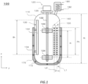
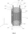
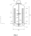
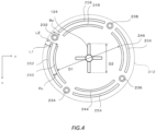
- FIG. 1 An example of a polymerization apparatus 100 is described in detail by using FIG. 1 , FIG. 2 , FIG. 3 , and FIG. 4 .
- the polymerization apparatus 100 is used, for example, for producing a polymer.
- the polymerization apparatus 100 may be used for application of suspension polymerization.
- the polymerization apparatus 100 is used for producing a vinyl-based polymer.
- a method for producing the vinyl-based polymer a method having a step for polymerizing a vinyl-based monomer by using the polymerization apparatus 100 to produce a vinyl-based polymer is exemplified.
- the above-described method for producing the vinyl-based polymer includes, for example, a step for storing raw material, including a vinyl-based monomer, in a reactor arranged in the polymerization apparatus 100.
- the above-described method for producing the vinyl-based polymer includes, for example, a step for starting a polymerization reaction of the above-described vinyl-based monomer and producing a vinyl-based polymer.
- FIG. 1 shows a schematic cross-sectional view of an example of the polymerization apparatus 100.
- the polymerization apparatus 100 includes a reaction vessel 110, an agitator 120, one or a plurality of (may be referred to simply as one or more) baffles 130, one or more serpentine cooling pipes 140, one or more serpentine cooling pipes 150, a jacket 170, and a reflux condenser 180.
- the agitator 120 includes an agitation shaft 122, an agitating blade 124, and a power mechanism 126.
- the baffle 130 includes a body 132 and one or more supports 134.
- the jacket 170 includes a flow channel 172 for a heat carrier.
- the reflux condenser 180 includes a flow channel 182 for a heat carrier.
- the agitation shaft 122 and the agitating blade 124 are arranged inside the reaction vessel 110.
- each of the one or more baffles 130 is arranged inside the reaction vessel 110.
- each of the one or more serpentine cooling pipes 140 is arranged inside the reaction vessel 110.
- each of the one or more serpentine cooling pipes 150 is arranged inside the reaction vessel 110.
- the power mechanism 126 is arranged outside the reaction vessel 110.
- the jacket 170 is arranged outside the reaction vessel 110.
- the reflux condenser 180 is arranged outside the reaction vessel 110.
- the serpentine cooling pipe 140 and the serpentine cooling pipe 150 are arranged so that their distances from an inner surface of the reaction vessel 110 are different. Specifically, the serpentine cooling pipe 150 is arranged at a position closer to a side surface of the reaction vessel 110 than the serpentine cooling pipe 140. In this case, a distance L2 from the serpentine cooling pipe 140 to the side surface of the reaction vessel 110 is greater than a distance L1 from the serpentine cooling pipe 150 to the side surface of the reaction vessel 110.
- the distance L2 from the serpentine cooling pipe 140 to the side surface of the reaction vessel 110 may be a minimum value of a distance from a center of a cross section of the serpentine cooling pipe 140 to the side surface of the reaction vessel 110.
- the distance L1 from the serpentine cooling pipe 150 to the side surface of the reaction vessel 110 may be a minimum value of a distance from a center of a cross section of the serpentine cooling pipe 150 to the side surface of the reaction vessel 110.
- the serpentine cooling pipe 140 or the serpentine cooling pipe 150 is a circular pipe
- the cross section of the serpentine cooling pipe 140 or the serpentine cooling pipe 150 is circular
- the center of the cross section of the serpentine cooling pipe 140 or the serpentine cooling pipe 150 is the center of said circle.
- heat inside the reaction vessel 110 can be removed efficiently.
- the polymerization apparatus 100 when used for producing a polymer, the polymerization apparatus 100 can efficiently remove heat of reaction generated in a polymerization reaction.
- particle size and/or degree of polymerization of the produced polymer tends to be nonuniform, and polymer scale tends to adhere to an inner wall or surfaces of the internal structures of the reaction vessel 110.
- the above-described scale can cause a fish eye that impairs quality of a molded product using a polymer.
- the serpentine cooling pipe 140 and the serpentine cooling pipe 150 are arranged so that their distances from the inner surface of the reaction vessel 110 are different.
- conduction area can be increased by using a relatively simple structure having a small effect on mixing performance of the polymerization apparatus 100.
- degree of freedom relating to installation positions of the serpentine cooling pipe 140 and the serpentine cooling pipe 150 is high.
- at least one of the one or more serpentine cooling pipes 140 or the one or more serpentine cooling pipes 150, and the baffle 130 can be arranged on substantially the same circumference.
- the conduction area of the entire apparatus can be increased while making the effect on the mixing performance of the polymerization apparatus 100 by the serpentine cooling pipe 150 smaller.
- the reaction vessel 110 stores material of a synthesizing reaction.
- the polymerization apparatus 100 is used for producing a polymer, for example, polymerization is started after a polymerizable monomer, a polymerization initiator, an aqueous media, a dispersing aid or the like is prepared inside the reaction vessel 110.
- a dispersing aid for example, any surfactant can be used as the dispersing aid.
- the reaction vessel 110 has a tubular shape.
- the reaction vessel 110 may have a cylindrical shape, and may have a rectangular tubular shape.
- the reaction vessel 110 is installed so that an extending direction of the reaction vessel 110 (z direction in the figure.) is a vertical direction.
- a shape of a cross section (may be referred to as a transverse section) of the reaction vessel 110 cut along a surface perpendicular to the extending direction of the reaction vessel 110 (x-y plane in the figure.) is exemplified.
- the shape of the transverse section of the reaction vessel 110 may be a shape that can be considered substantially as a circular, oval, or polygonal shape.
- An internal capacity of the reaction vessel 110 is not limited in particular, but the internal capacity of the reaction vessel 110 is, for example, 1 to 300 m 3 .
- a lower limit value of the internal capacity of the reaction vessel 110 may be 40 m 3 , may be 80 m 3 , may be 100 m 3 , may be 120 m 3 , may be 130 m 3 , may be 150 m 3 , may be 200 m 3 , and may be 250 m 3 .
- An upper limit value of the internal capacity of the reaction vessel 110 may be 300 m 3 or more.
- the upper limit value of the internal capacity of the reaction vessel 110 may be 350 m 3 , and may be 400 m 3 .
- the greater the internal capacity of the reaction vessel 110 improvement of cooling power according to the present embodiment can be done more advantageously.
- the internal capacity of the reaction vessel 110 is defined as a capacity when the reaction vessel 110 stores liquid up to a predetermined upper limit position of the reaction vessel 110.
- the internal capacity of the reaction vessel 110 is, for example, a volume inside the reaction vessel 110 when internal structures such as an agitating shaft, wings, baffle, coil or the like are not arranged inside the reaction vessel 110.
- the agitator 120 agitates liquid stored inside the reaction vessel 110.
- the agitation shaft 122 holds the agitating blade 124 and rotates the agitating blade 124.
- the agitating blade 124 is attached to the agitation shaft 122 and agitates liquid stored inside the reaction vessel 110.
- a shape of the agitating blade 124 is not limited in particular, but a Pfaudler blade, blue margin blade, paddle blade, inclined paddle blade, turbine blade, propeller blade, and combinations thereof are exemplified as the shape of the agitating blade 124.
- a quantity of blades that the agitating blade 124 includes is not limited in particular, but 2 to 6 blades are exemplified as the quantity of the above-described blades.
- An installation position and installation number of the agitating blade 124 are not limited in particular, but the agitating blade 124 is preferably installed in multiple layers. As a number of layers of the agitating blade 124, 2 to 6 layers are exemplified.
- the power mechanism 126 rotates the agitation shaft 122.
- the power mechanism 126 includes a power portion (not shown.) that generates power and a power transmission portion (not shown.) that transmits power generated by the power portion to the agitation shaft 122.
- a power portion an electric motor is exemplified.
- a reduction gear is exemplified.
- a number of rotations of the agitation shaft 122, as well as the shape, the size, the quantity of blades, the installation position, the installation number, and an installation interval Pi of the agitating blade 124 are decided appropriately according to an application of the polymerization apparatus 100.
- the number of rotations of the agitation shaft 122, as well as the shape, the size, the quantity of blades, the installation position, the installation number, and the installation interval Pi of the agitating blade 124 are, for example, decided in consideration of the internal capacity of the reaction vessel 110, the shape of the reaction vessel 110, the internal structures arranged inside the reaction vessel 110, a configuration of the heat removal means, heat removal capacity, and composition of raw material prepared for polymerization.
- the number of rotations of the agitation shaft 122 is decided so that agitation energy applied to content (aqueous suspension mixture in this case.) is 80 to 200 kgf ⁇ m/s ⁇ m 3 .
- the "agitation energy" applied to the content is defined as net energy required for agitating per unit amount (may be referred to as unit internal capacity.) of the content that is obtained by subtracting various types of energy loss B such as motor efficiency, conduction loss, mechanical loss or the like from energy A that is loaded on an agitator drive motor arranged in the power mechanism 126, during operation of the polymerization apparatus 100.
- energy loss B such as motor efficiency, conduction loss, mechanical loss or the like
- unit mass, unit volume or the like are exemplified.
- the agitation energy is calculated by the following Expression 1.
- the energy loaded on the agitator drive motor for example, can be measured electrically by using a measurement device such as a watt meter or the like.
- the agitation energy can be adjusted easily by changing the number of rotations of the agitation shaft 122.
- the number of rotations of the agitation shaft 122 in the polymerization apparatus 100 is decided based on a polymerization test performed in advance in a pilot plant. Generally, scale-up from the pilot plant to the polymerization apparatus 100 is performed so that an agitation state of the polymerization apparatus 100 and an agitation state of the pilot plant are substantially identical. For example, in the pilot plant and the polymerization apparatus 100, a shape, size, and arrangement of each internal structure is decided so that the shape and size of the reaction vessel 110, and the shape, size, and arrangement of the internal structures such as the agitating blade 124, the baffle 130, the serpentine cooling pipe 140, the serpentine cooling pipe 150 or the like are similar.
- the number of rotations of the agitation shaft 122 in the polymerization apparatus 100 can be decided so that the agitation energy in the polymerization apparatus 100 and the agitation energy in the pilot plant are substantially the same.
- the agitation energy is, for example, calculated as "(A-B)/C".
- any well-known approach can be adopted.
- the number of rotations of the agitation shaft 122 in the pilot plant is, for example, decided by the following procedure. For example, a relationship between the number of rotations of the agitation shaft 122 in the pilot plant and quality of a polymer is obtained by a polymerization test using the pilot plant. Thus, the number of rotations of the agitation shaft 122 with which a polymer of desired quality can be obtained is decided.
- the above-described quality is not limited in particular, but as the above-described quality, for example, particle size is exemplified.
- a polymerization temperature is set according to a desired reduced viscosity of the polymer (may be referred to as K-value.).
- K-value a desired reduced viscosity of the polymer
- the polymerization temperature and an average degree of polymerization of a polymer are correlated, and the K-value of the polymer is used widely as an indicator expressing the average degree of polymerization of the polymer.
- a polymerization time is decided according to heat removal capacity of the pilot plant.
- the polymerization time is decided according to (i) preparation amount of a monomer that is a starting material, (ii) input amount of a polymerization initiator, and (iii) the heat removal capacity of the pilot plant, so that a calorific value of a reaction does not exceed the heat removal capacity of the pilot plant.
- a polymer having a desired average degree of polymerization can be generated by setting the polymerization temperature according to a target K-value. For example, a polymerization test is performed for each of a plurality of conditions in which the polymerization temperature and the polymerization time is the same, and the number of rotations of the agitation shaft 122 is different.
- the relationship between the number of rotations of the agitation shaft 122 in the pilot plant and the quality of the polymer is obtained.
- the number of rotations of the agitation shaft 122 by which a polymer of the desired quality can be decided.
- the K-value of the generated polymer can be adopted as an indicator that relates to heat removal capacity of the polymerization apparatus 100.
- the polymerization apparatus 100 can be determined to have sufficient heat removal capacity.
- scale-up from the pilot plant to the polymerization apparatus 100 can be performed so that the agitation state of the polymerization apparatus 100 and the agitation state of the pilot plant are substantially identical.
- a ratio of size of each internal structure arranged inside the reaction vessel 110 in relation to an inner diameter and/or straight body height of the reaction vessel 110 in a desired polymerization apparatus 100 and a ratio of the size of each internal structure in the pilot plant in relation to an inner diameter and/or straight body height of the reaction vessel of the pilot plant are substantially identical
- the agitation energy in the polymerization apparatus 100 and the agitation energy in the pilot plant are substantially the same
- the agitation state of the scaled up polymerization apparatus 100 and the agitation state of the pilot plant are substantially identical.
- a size of the baffle 130 in the desired polymerization apparatus 100 is decided so that ratios of a length of the baffle 130 in its extending direction (up and down direction in the figure) in relation to the straight body height of the reaction vessel 110 between the pilot plant and the desired polymerization apparatus 100 are substantially the same.
- the size of the baffle 130 in the desired polymerization apparatus 100 is decided so that the ratios of a length of the baffle 130 in a direction that is substantially perpendicular to its extending direction (left and right directions in the figure) in relation to a diameter inside the reaction vessel 110 (may be referred to as inner diameter.) between the pilot plant and the desired polymerization apparatus 100 are substantially the same.
- the number of the baffle 130 and its arrangement in the desired polymerization apparatus 100 are decided so that the number of the baffle 130 and its arrangement are substantially the same between the pilot plant and the desired polymerization apparatus 100. It is similar for another structure (for example, the agitating blade 124, the serpentine cooling pipe 140, the serpentine cooling pipe 150 or the like.).
- the number of rotations of the agitation shaft 122 in the scaled up polymerization apparatus 100 can be decided based on the relationship between the number of rotations of the agitation shaft 122 in the pilot plant and the quality of the polymer described above. Specifically, first, the number of rotations of the agitation shaft 122 in the pilot plant is decided based on (i) the target value of the quality of the polymer in the polymerization apparatus 100, and (ii) the relationship between the number of rotations of the agitation shaft 122 in the pilot plant and the quality of the polymer. Then, the number of rotations of the agitation shaft 122 in the polymerization apparatus 100 is decided so that the agitation energy in the polymerization apparatus 100 and the agitation energy in the pilot plant are substantially the same.
- the number of rotations of the agitation shaft 122 of the desired polymerization apparatus 100 can be decided in consideration of (i) the shape, size, quantity of blades, installation position, installation number, and installation interval Pi of the agitating blade 124, as well as (ii) the internal capacity of the reaction vessel 110, the shape of the reaction vessel 110, and the internal structures or the like arranged inside the reaction vessel 110 of the desired polymerization apparatus 100, without strictly measuring the above-described agitation energy per unit internal capacity (kgf ⁇ m/s ⁇ m 3 ).
- the number of rotations of the agitation shaft 122 in the desired polymerization apparatus 100 may be decided based on a simulation result of a polymerization test.
- the baffle 130 improves the mixing performance of the polymerization apparatus 100.
- the baffle 130 improves mixing performance of the up and down direction inside the reaction vessel 110.
- Installation position of the baffle 130 is not limited in particular, but for example, the baffle 130 is arranged nearby the inner wall of the reaction vessel 110.
- the baffle 130 may be supported by the side wall of the reaction vessel 110.
- the baffle 130 is supported by a top plate or a bottom plate of the reaction vessel 110, and is arranged nearby the agitating blade 124.
- the baffle 130 may be arranged so that an upper end of the baffle 130 is submerged in a liquid phase, and may be arranged so that the upper end of the baffle 130 is not submerged in the liquid phase.
- the number of the baffles 130 is preferably approximately 1 to 12, preferably approximately 2 to 8, more preferably approximately 3 to 6, and further preferably approximately 4 to 6. It is preferable that an even number of the baffles 130 is arranged substantially symmetrically around an extending axis of the reaction vessel 110 (may be referred to as a central axis.). Thus, the mixing performance of the polymerization apparatus 100 is further improved, and stagnation of liquid is suppressed. As a result, generation of scale can be suppressed.
- the body 132 of the baffle 130 improves the mixing performance of the polymerization apparatus 100.
- a shape of the body 132 is not limited in particular, but for example, the body 132 has a plate-like or tubular shape extending substantially parallel to the extending direction of the reaction vessel 110. When the body 132 has a cylindrical shape, a diameter of the body 132 may be 40 to 500 mm.
- a length Bh (may be referred to as height Bh.) of an extending direction of the body 132 (z direction in the figure.) is not limited in particular.
- a length Bw (may be referred to as width Bw.) of a direction that is substantially perpendicular to the extending direction of the body 132 (x or y direction in the figure.) is not limited in particular.
- a proportion of the width Bw of the body 132 in relation to the inner diameter of the reaction vessel 110 may be 1 to 10%, may be 2.5 to 7.5 %, and may be 3 to 7%.
- a proportion of a total value of areas of transverse sections of one or more bodies 132 each having a tubular shape, in relation to an area of a transverse section of the straight body of the reaction vessel 110 may be 0.4 to 3%.
- the above-described proportion is less than 0.4%, there is a chance that function as a baffle plate is insufficient, and mixing in the up and down direction inside the reaction vessel 110 becomes poor.
- the polymerization apparatus 100 includes a single baffle 130, the above-described proportion can become less than 0.4%.
- the above-described proportion exceeds 3%, the power requirement of the agitator 120 increases excessively. Flowability of liquid between the baffle 130 and the inner wall surface of the reaction vessel 110 can also decrease. As a result, there is a chance that scale tends to adhere to the reaction vessel 110 or a structure inside the reaction vessel 110.
- the above-described proportion can exceed 3% depending on a design of the polymerization apparatus 100.
- the body 132 of at least one baffle 130 may include a flow channel for circulating a heat carrier.
- the above-described flow channel may be formed inside the body 132 and may be arranged outside the body 132.
- the above-described flow channel may be a single layer pipe and may have a double pipe structure.
- the heat carrier may be a well-known coolant.
- the coolant water, brine, freon, another liquefied gas or the like are exemplified.
- a liquefied gas used as the coolant, said liquefied gas may function as the coolant by evaporating inside the serpentine cooling pipe 140.
- a linear speed of the coolant may be approximately 0.1 to 6.0 m/s.
- the body 132 is, for example, connected to the inner wall surface of the reaction vessel 110 via the support 134.
- a distance between the body 132 and the inner wall surface of the polymerization apparatus 100 is preferably 40 mm or more. When the above-described distance is less than 40 mm, near a gas-liquid interface inside the reaction vessel 110, polymer scale may tend to adhere between the inner wall surface of the reaction vessel 110 and the baffle 130. Detail of the body 132 is described below.
- the support 134 holds the body 132.
- one end of the support 134 is in contact with the inner wall surface of the reaction vessel 110, and another end of the support 134 is in contact with the body 132.
- the support 134 may hold the body 132 so that the distance between the body 132 and the inner wall surface of the polymerization apparatus 100 is 40 mm or more.
- a flow channel for circulating a heat carrier inside is formed in the serpentine cooling pipe 140.
- the serpentine cooling pipe 140 may be a single layer pipe.
- the serpentine cooling pipe 140 is arranged at a position closer to the central axis of the reaction vessel 110 than the serpentine cooling pipe 150.
- the number of the serpentine cooling pipes 140 is preferably approximately 1 to 12, preferably approximately 2 to 8, more preferably approximately 3 to 6, and further preferably approximately 4 to 6. It is preferable that an even number of the serpentine cooling pipes 140 is arranged substantially symmetrically around the central axis of the reaction vessel 110.
- the heat carrier may be a well-known coolant.
- the coolant water, brine, freon, another liquefied gas or the like are exemplified.
- a liquefied gas used as the coolant, said liquefied gas may function as the coolant by evaporating inside the serpentine cooling pipe 140.
- a linear speed of the coolant may be approximately 0.1 to 6.0 m/s.
- At least one part of the serpentine cooling pipe 140 extends while repeatedly bending.
- a length Ph in an extending direction of the portion that extends while repeatedly bending may be less than a length Bh in the extending direction of the body 132 of the baffle 130 (z direction in the figure.), may be substantially the same as said Bh, and may be greater than said Bh.
- conduction area per installation area increases.
- the serpentine cooling pipe 140 extends substantially parallel to the extending direction of the reaction vessel 110 while repeatedly bending.
- the entire serpentine cooling pipe 140 extends while repeatedly bending.
- a proportion of the length Ph in the extending direction of the portion that extends while repeatedly bending within the serpentine cooling pipe 140, in relation to a full length Pt (not shown.) in an extending direction of the serpentine cooling pipe 140 may be 0.25 or more, may be 0.5 or more, may be 0.75 or more, may be 0.8 or more, and may be 0.9 or more.
- the serpentine cooling pipe 140 may be arranged so that an upper end of the serpentine cooling pipe 140 is submerged in a liquid phase. This is because when an upper part of the serpentine cooling pipe 140 is exposed to a gas phase, conduction efficiency tends to decrease, and polymer scale tends to adhere to the serpentine cooling pipe 140. In end stage polymerization, the gas-liquid interface decreases due to liquid shrinkage. Therefore, even at a polymerization ending time, the serpentine cooling pipe 140 is preferably arranged in a position so that there is a sufficient distance between the upper end of the serpentine cooling pipe 140 and the gas-liquid interface. Detail of the serpentine cooling pipe 140 is described below.
- a flow channel for circulating a heat carrier inside is formed in the serpentine cooling pipe 150.
- the serpentine cooling pipe 150 may be a single layer pipe.
- the serpentine cooling pipe 150 is arranged at a position closer to the side wall of the reaction vessel 110 than the serpentine cooling pipe 140.
- the number of the serpentine cooling pipes 150 is preferably approximately 1 to 12, preferably approximately 2 to 8, more preferably approximately 3 to 6, and further preferably approximately 4 to 6.
- the number of the serpentine cooling pipes 150 may be the same as the number of the serpentine cooling pipes 140, and may be different. It is preferable that an even number of the serpentine cooling pipes 150 is arranged substantially symmetrically around the central axis of the reaction vessel 110.
- the heat carrier may be a well-known coolant.
- the coolant water, brine, freon, another liquefied gas or the like are exemplified.
- a liquefied gas used as the coolant, said liquefied gas may function as the coolant by evaporating inside the serpentine cooling pipe 140.
- a linear speed of the coolant may be approximately 0.1 to 6.0 m/s.
- At least one part of the serpentine cooling pipe 150 extends while repeatedly bending.
- a length Ph in an extending direction of the portion that extends while repeatedly bending may be less than a length Bh in the extending direction of the body 132 of the baffle 130 (z direction in the figure.), may be substantially the same as said Bh, and may be greater than said Bh.
- conduction area per installation area increases.
- the serpentine cooling pipe 150 extends substantially parallel to the extending direction of the reaction vessel 110 while repeatedly bending.
- the entire serpentine cooling pipe 150 extends while repeatedly bending.
- a proportion of the length Ph in the extending direction of the portion that extends while repeatedly bending within the serpentine cooling pipe 150, in relation to a full length Pt (not shown.) in an extending direction of the serpentine cooling pipe 150 may be 0.25 or more, may be 0.5 or more, may be 0.75 or more, may be 0.8 or more, and may be 0.9 or more.
- the serpentine cooling pipe 150 may be arranged so that an upper end of the serpentine cooling pipe 150 is submerged in a liquid phase. This is because when an upper part of the serpentine cooling pipe 150 is exposed to a gas phase, conduction efficiency tends to decrease, and polymer scale tends to adhere to the serpentine cooling pipe 150. In end stage polymerization, the gas-liquid interface decreases due to liquid shrinkage. Therefore, even in at the polymerization ending time, the serpentine cooling pipe 150 is preferably arranged in a position so that there is a sufficient distance between the upper end of the serpentine cooling pipe 150 and the gas-liquid interface.
- a circulation direction of coolant in the serpentine cooling pipe 150 is set so that coolant flows from a bottom of the reaction vessel 110 toward a top of the reaction vessel 110. In another embodiment, the circulation direction of coolant in the serpentine cooling pipe 150 is set so that coolant flows from the top of the reaction vessel 110 toward the bottom of the reaction vessel 110.
- liquid that is returned from the reflux condenser 180 has a lower temperature than liquid inside the reaction vessel 110, and has high density. Therefore, nearby an inlet for liquid that is returned from the reflux condenser 180, there is a tendency for liquid inside the reaction vessel 110 to flow from top to bottom.
- the serpentine cooling pipe 150 arranged nearby the inlet for liquid that is returned from the reflux condenser 180 can be configured so that the coolant circulates from the bottom of the reaction vessel 110 toward the top of the reaction vessel 110. Detail of the serpentine cooling pipe 150 is described below.
- the jacket 170 heats and cools the reaction vessel 110 from outside the reaction vessel 110.
- the jacket 170 includes the flow channel 172 that is configured to allow circulation of a heat carrier.
- the jacket 170 adjusts heating amount and heat removal amount to and from the reaction vessel 110 by controlling at least one of a temperature or a volumetric flow rate of the heat carrier flowing through the flow channel 172.
- the heat carrier may be a well-known coolant.
- the coolant water, brine, freon, various liquefied gas or the like are exemplified.
- a liquefied coolant is preferably used.
- said liquefied gas may function as the coolant by evaporating inside the serpentine cooling pipe 140.
- a linear speed of the coolant may be approximately 0.1 to 6.0 m/s.
- the reflux condenser 180 is used for heat removal of the reaction vessel 110.
- the reflux condenser 180 is supplied with steam from the reaction vessel 110.
- the reflux condenser 180 cools and liquefies the above-described steam.
- the reflux condenser 180 returns the liquid generated by the above-described cooling to the reaction vessel 110.
- the reflux condenser 180 includes the flow channel 182 that is configured to allow circulation of a heat carrier.
- the reflux condenser 180 cools the steam from the reaction vessel 110 by heat exchange between the heat carrier circulating through the flow channel 182, and the steam from the reaction vessel 110.
- the heat removal amount from the reaction vessel 110 can be adjusted by controlling at least one of a temperature or a volumetric flow rate of the heat carrier flowing through the flow channel 182.
- the reaction vessel 110 includes, as heat removal means, the baffle 130, the serpentine cooling pipe 140, the serpentine cooling pipe 150, the jacket 170, and the reflux condenser 180.
- a proportion of a heat removal amount removed by using each heat removal apparatus, in relation to a gross calorific value is not limited in particular. The above-described proportion is, for example, decided in consideration of quality, production cost or the like of the produced polymer.
- a proportion of a heat removal amount by the baffle 130 in relation to the gross calorific value is preferably 10 to 30%.
- a proportion of a total heat removal amount by the serpentine cooling pipe 140 and the serpentine cooling pipe 150 in relation to the gross calorific value is preferably 10 to 50%.
- a proportion of the heat removal amount by the jacket 170 in relation to the gross calorific value is preferably 20 to 40%.
- a proportion of the heat removal amount by the reflux condenser 180 in relation to the gross calorific value is preferably 10 to 50%.
- the serpentine cooling pipe 140 and the serpentine cooling pipe 150 are preferably designed so that a ratio of a total surface area value of the serpentine cooling pipe 140 and the serpentine cooling pipe 150, in relation to the internal capacity of the reaction vessel 110 is 0.1 to 0.9 m 2 /m 3 .
- the above-described ratio is more preferably 0.5 to 0.7 m 2 /m 3 .
- the proportion of the total heat removal amount of the serpentine cooling pipe 140 and the serpentine cooling pipe 150 in relation to the gross calorific value can be 10 to 50%.
- Material of each unit of the polymerization apparatus 100 is decided appropriately in consideration of mechanical strength, corrosion resistance, heat transfer properties or the like.
- material used for the agitation shaft 122, the agitating blade 124, the baffle 130, the serpentine cooling pipe 140, and the serpentine cooling pipe 150 is preferably stainless steel such as high-chromium high-purity ferritic stainless steel, duplex stainless steel, austenitic stainless steel or the like. These materials have excellent heat transfer properties and corrosion resistance.
- material for the inner wall surface of the reaction vessel 110 clad steel including stainless steel is exemplified. Material of an outer layer of the above-described clad steel is preferably carbon steel, and material of an inner layer of said clad steel is preferably stainless steel.
- the polymerization apparatus 100 is used for producing a polymer.
- a polymerization method may be suspension polymerization, and may be emulsion polymerization. More specifically, the polymerization apparatus 100 is used for application of producing a polymer by polymerizing various vinyl-based monomers, for example, olefins such as ethylene, propylene or the like, vinyl halides such as vinyl chloride, vinylidene chloride or the like, vinyl esters such as vinyl acetate or the like, vinyl ethers such as ethyl vinyl ether or the like, (meth)acrylic acid esters such as methyl methacrylate or the like, metal salts or esters of maleic acid or fumaric acid, aromatic vinyls such as styrene or the like, diene monomers such as butadiene, chloroprene, isoprene or the like, and acrylonitrile or the like.
- the polymerization apparatus 100 is particularly suitably used for application of producing a polymer by poly
- each material is supplied from a supply port (not shown) of the polymerization apparatus, and at a time when a temperature of a reaction chemical compound prepared inside the reaction vessel 110 reaches a predetermined temperature, coolant is circulated through each of the baffle 130, the serpentine cooling pipe 140, the serpentine cooling pipe 150, and the jacket 170, and heat removal of said reaction chemical compound is started.
- a time to start heat removal by the reflux condenser 180 is preferably when a polymerization conversion rate reaches 4% or later, and is more preferably when the polymerization conversion rate is 4 to 20%.
- various polymerization conditions may be similar to well-known polymerization conditions.
- preparation proportion of material or the like, preparation method of material or the like, polymerization temperature or the like are exemplified.
- a vinyl chloride-based polymer is produced by suspension polymerization by using the polymerization apparatus 100
- preparation of an aqueous media, vinyl chloride monomer, in some cases another comonomer, dispersing aid, polymerization initiator or the like is performed similarly to a well-known method for producing a vinyl chloride-based polymer.
- Polymerization conditions may be similar to that of the well-known method for producing a vinyl chloride-based polymer.
- a monomer to be polymerized other than vinyl chloride alone, a monomer mixture mainly composed of vinyl chloride (50% by mass or more of vinyl chloride) can be used.
- a comonomer to be copolymerized with vinyl chloride for example, vinyl esters such as vinyl acetate, vinyl propionate or the like; acrylic acid esters or methacrylic acid esters such as methyl acrylate, ethyl acrylate or the like; olefins such as ethylene, propylene or the like; maleic anhydride; acrylonitrile; styrene; vinylidene chloride; and other monomers that can be copolymerized with vinyl chloride are exemplified.
- dispersing aid a chemical compound used normally when polymerizing vinyl chloride in aqueous media is used.
- water soluble cellulose ethers such as methylcellulose, hydroxyethylcellulose, hydroxypropylcellulose, hydroxypropylmethylcellulose or the like; partially saponified polyvinyl alcohol, acrylic acid polymers; and water-soluble polymers or the like such as gelatin or the like are exemplified.
- the above-described dispersing aid may be used alone, and may be used in a combination of two types or more.
- the dispersing aid is, for example, added in an amount of 0.01 to 5 parts by mass per 100 parts by mass of prepared monomer.
- the polymerization initiator to be used may be what is conventionally used for vinyl chloride-based polymerization.
- percarbonate compounds such as diisopropyl peroxydicarbonate, di-2-ethylhexyl peroxydicarbonate, diethoxyethyl peroxydicarbonate or the like; perester compounds such as ⁇ -cumylperoxyneodecanate, t-butylperoxyneodecanate, t-butylperoxyneoheptanoate, hexylperoxyneodecanate, octylperoxyneodecanate or the like; peroxides such as acetylcyclohexylsulfonyl peroxide, 2,4,4-trimethylpentyl-2-peroxyphenoxyacetate or the like; and azo compounds such as azobis-2,4-dimethylvaleronitrile, azobis(4-
- the above-described polymerization initiator may be used alone, and may be used in a combination of two types or more.
- the polymerization initiator for example, may be added in an amount of 0.01 to 3 parts by mass per 100 parts by mass of monomer, and is preferably added in an amount of 0.05 to 3 parts by mass per 100 parts by mass of monomer.
- a polymerization modifier, chain transfer agent, pH adjuster, buffer, gelling improver, antistatic agent, scale inhibitor or the like used appropriately for vinyl chloride polymerization can be added.
- K-value reduced viscosity
- citric acid trisodium citrate, diammonium citrate, triammonium citrate, potassium hydrogen phthalate, sodium nitrate, sodium carbonate, potassium carbonate, cesium carbonate, sodium hydrogen carbonate, sodium hydroxide, potassium hydroxide, barium hydroxide, disodium phosphate, dipotassium phosphate, tripotassium phosphate or the like are exemplified.
- the above-described pH adjuster or buffer may be used alone, and may be used in a combination of two types or more.
- the polymerization apparatus 100 may be an example of a reaction apparatus.
- the reaction vessel 110 may be an example of a reactor.
- the inner surface of the reaction vessel 110 may be an example of an inner wall surface of the reactor.
- the side surface of the reaction vessel 110 may be an example of the inner wall surface of the reactor.
- the flow channel for the heat carrier arranged in the body 132 of the baffle 130 may be an example of a second cooling pipe.
- the support 134 of the baffle 130 may be an example of at least one part of a baffle.
- the serpentine cooling pipe 140 may be an example of a first cooling pipe.
- the serpentine cooling pipe 150 may be an example of a first cooling pipe.
- One of the serpentine cooling pipe 140 and one of the serpentine cooling pipe 150 may be an example of at least two of a plurality of the first cooling pipe.
- the flow channel 172 may be an example of a third cooling pipe.
- the flow channel 182 may be an example of a third cooling pipe.
- FIG. 2 schematically shows an example of internal structures arranged inside the reaction vessel 110.
- the polymerization apparatus 100 includes a baffle 232, a baffle 234, a baffle 236, and a baffle 238.
- the polymerization apparatus 100 includes a serpentine cooling pipe 242, a serpentine cooling pipe 244, a serpentine cooling pipe 246, and a serpentine cooling pipe 248.
- the serpentine cooling pipe 150 the polymerization apparatus 100 includes a serpentine cooling pipe 252, a serpentine cooling pipe 254, a serpentine cooling pipe 256, and a serpentine cooling pipe 258.
- FIG. 3 shows a schematic cross-sectional view of an example of the reaction vessel 110.
- representation of the serpentine cooling pipe 140 is omitted for sake of clarity.
- installation positions of the baffle 232, the baffle 234, the baffle 236, and the baffle 238 are deformed.
- the reaction vessel 110 includes a straight body 312, a first panel 314, a second panel 316, and a pedestal 318.
- the straight body 312 has a cylindrical shape.
- a length in an extending direction of the straight body 312 is Hb
- an inner diameter of the straight body 312 is Db
- the straight body 312 is, for example, designed so that a value of Hb/Db is 1.0 to 3.0.
- the straight body 312 may be designed so that the value of Hb/Db is 1.5 to 2.5.
- the first panel 314 is combined to one end of the straight body 312, and configures a bottom plate of the reaction vessel 110.
- the second panel 316 is combined to another end of the straight body 312, and configures a top plate of the reaction vessel 110.
- the pedestal 318 holds the power mechanism 126.
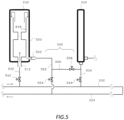
- a coolant supplying pipe 332 for supplying coolant from a coolant source to the reaction vessel 110, and a coolant returning pipe 334 for returning coolant after heat exchange from the reaction vessel 110 to the coolant source are arranged around the polymerization apparatus 100.
- the baffle 232 and the baffle 234 are coupled by a coupling portion 342, and configured so that coolant flowing out from the baffle 232 can flow into the baffle 234.
- the baffle 234 and the baffle 236 are coupled by a coupling portion 344, and configured so that coolant flowing out from the baffle 234 can flow into the baffle 236.
- the baffle 236 and the baffle 238 are coupled by a coupling portion 346, and configured so that coolant flowing out from the baffle 236 can flow into the baffle 238. Detail of each baffle is described below.
- coolant supplied from the coolant supplying pipe 332 to the reaction vessel 110 flows into the baffle 232, passes through the baffle 234, the baffle 236, and the baffle 238, and is ejected into the coolant returning pipe 334.
- a circulating method of the coolant is not limited to the present embodiment.
- coolant supplied from the coolant supplying pipe 332 to the reaction vessel 110 flows into the baffle 232, passes through the baffle 234, and is ejected into the coolant returning pipe 334.
- Coolant supplied from the coolant supplying pipe 332 to the reaction vessel 110 flows into the baffle 238, passes through the baffle 236, and is ejected into the coolant returning pipe 334.
- each of the baffle 232, the baffle 234, the baffle 236, and the baffle 238 are configured so that volumetric flow rate of coolant supplied to each baffle is independently controllable.
- FIG. 4 shows a schematic plan view of an example of the reaction vessel 110.
- the baffle 232, the baffle 234, the baffle 236, and the baffle 238, (ii) the serpentine cooling pipe 242, the serpentine cooling pipe 244, the serpentine cooling pipe 246, and the serpentine cooling pipe 248, and (iii) the serpentine cooling pipe 252, the serpentine cooling pipe 254, the serpentine cooling pipe 256, and the serpentine cooling pipe 258 are arranged concentrically.
- the serpentine cooling pipe 242, the serpentine cooling pipe 244, the serpentine cooling pipe 246, and the serpentine cooling pipe 248 are arranged on substantially the same circumference.
- the baffle 232, the baffle 234, the baffle 236, and the baffle 238, (ii) the serpentine cooling pipe 252, the serpentine cooling pipe 254, the serpentine cooling pipe 256, and the serpentine cooling pipe 258 are arranged on substantially the same circumference.
- a center of the transverse section of the baffle 232, the baffle 234, the baffle 236, and the baffle 238, and a center of the transverse section of the serpentine cooling pipe 252, the serpentine cooling pipe 254, the serpentine cooling pipe 256, and the serpentine cooling pipe 258 are arranged on substantially the same circumference.
- the transverse section at the particular position of the straight body 312 is a surface (x-y plane in the figure.) perpendicular to the extending direction (z direction in the figure.) of the straight body 312, a plane that passes through the center of the serpentine cooling pipe 252, the serpentine cooling pipe 254, the serpentine cooling pipe 256, and the serpentine cooling pipe 258, and may be a cross section obtained by cutting the reaction vessel 110.
- a width of each pipe in the transverse section is identical to a diameter of each pipe.
- the baffle 232, the baffle 234, the baffle 236, and the baffle 238 are arranged at substantially symmetrical positions around the central axis of the reaction vessel 110.
- the serpentine cooling pipe 242, the serpentine cooling pipe 244, the serpentine cooling pipe 246, and the serpentine cooling pipe 248 are arranged at substantially symmetrical positions around the central axis of the reaction vessel 110.
- the serpentine cooling pipe 252, the serpentine cooling pipe 254, the serpentine cooling pipe 256, and the serpentine cooling pipe 258 are arranged at substantially symmetrical positions around the central axis of the reaction vessel 110.
- the serpentine cooling pipe 252 is arranged at a position between the baffle 232 and the baffle 234.
- the serpentine cooling pipe 254 is arranged at a position between the baffle 234 and the baffle 236.
- the serpentine cooling pipe 256 is arranged at a position between the baffle 236 and the baffle 238.
- the serpentine cooling pipe 258 is arranged at a position between the baffle 238 and the baffle 232.
- a diameter of an outer circumference of the serpentine cooling pipe 252, the serpentine cooling pipe 254, the serpentine cooling pipe 256, and the serpentine cooling pipe 258 may be less than a width Bw of the baffle 232, the baffle 234, the baffle 236, and the baffle 238.
- a diameter of a circle on which the serpentine cooling pipe 242, the serpentine cooling pipe 244, the serpentine cooling pipe 246, and the serpentine cooling pipe 248 are arranged is less than a diameter of a circle on which the serpentine cooling pipe 252, the serpentine cooling pipe 254, the serpentine cooling pipe 256, and the serpentine cooling pipe 258 are arranged.
- the serpentine cooling pipes can be arranged in multiple layers in a diameter direction of the straight body 312 of the reaction vessel 110.
- a size of a diameter D1 of a virtual circle on which the outer circumference of the serpentine cooling pipe 242, the serpentine cooling pipe 244, the serpentine cooling pipe 246, and the serpentine cooling pipe 248 are arranged is not limited in particular, but it is preferably greater than a diameter D2 of a rotation region of the agitating blade 124.
- D1/D2 is preferably 1.1 or more, and more preferably 1.2 or more.
- a distance between each of the serpentine cooling pipe 252, the serpentine cooling pipe 254, the serpentine cooling pipe 256, and the serpentine cooling pipe 258, and an inner surface of the straight body 312 are all L1.
- a distance between each of the serpentine cooling pipe 242, the serpentine cooling pipe 244, the serpentine cooling pipe 246, and the serpentine cooling pipe 248, and an inner surface of the straight body 312 are all L2.
- L2 > L1.
- L1 is preferably set so that a distance between an outer circumference of each serpentine cooling pipe and the inner surface of the straight body 312 is 40 mm or more. It may be set so that L1 is 40 mm or more. When the above-described distance or L1 is less than 40 mm, near a gas-liquid interface inside the reaction vessel 110, polymer scale may tend to adhere between the inner wall surface of the reaction vessel 110 and the serpentine cooling pipes 150.
- a distance Pc between the serpentine cooling pipe 242 and the serpentine cooling pipe 252 is preferably 40 mm or more.
- the distance Pc is, for example, decided by calculating a minimum value of a distance between an outer circumference of the serpentine cooling pipe 242 and an outer circumference of the serpentine cooling pipe 252, in the above-described transverse section. When Pc is less than 40 mm, polymer scale may tend to adhere.
- a distance between a particular serpentine cooling pipe and the inner surface of the straight body 312 may be decided as a minimal distance between both in a cross section that is perpendicular to the extending direction of the straight body 312 and passes through a center of said particular serpentine cooling pipe.
- a distance between each serpentine cooling pipe and the inner surface of the straight body 312 is, for example, decided by calculating a minimum value of a distance between a center line along an extending direction of each serpentine cooling pipe and the inner surface of the straight body 312, in the above-described transverse section.
- the above-described center line along the extending direction of each serpentine cooling pipe curves in an arc shape. Detail of the above-described distance is described below.
- transverse sections of the serpentine cooling pipe 242, the serpentine cooling pipe 244, the serpentine cooling pipe 246, and the serpentine cooling pipe 254 have an arc shape.
- transverse sections of the serpentine cooling pipe 252, the serpentine cooling pipe 254, the serpentine cooling pipe 256, and the serpentine cooling pipe 258 have an arc shape.
- the shapes of the transverse sections of the serpentine cooling pipe 242, the serpentine cooling pipe 244, the serpentine cooling pipe 246, and the serpentine cooling pipe 254, and the shapes of the transverse sections of the serpentine cooling pipe 252, the serpentine cooling pipe 254, the serpentine cooling pipe 256, and the serpentine cooling pipe 258 may be similar in shape.
- a central angle of the arc of the serpentine cooling pipe 242 and a central angle of the arc of the serpentine cooling pipe 252 may be substantially the same.
- the serpentine cooling pipe 244 and the serpentine cooling pipe 254, the serpentine cooling pipe 246 and the serpentine cooling pipe 256, as well as the serpentine cooling pipe 248 and the serpentine cooling pipe 258 may be similar.
- a size of a central angle of the arc may be 270 degrees or less.
- the size of the central angle of the arc may be 240 degrees or less, may be 210 degrees or less, may be 180 degrees or less, may be 150 degrees or less, may be 120 degrees or less, may be 90 degrees or less, and may be 60 degrees or less.
- a length in an extending direction of at least one of the serpentine cooling pipe 252, the serpentine cooling pipe 254, the serpentine cooling pipe 256, and the serpentine cooling pipe 258 is less than two-thirds of a length of an inner circumference of the straight body 312.
- the above-described length in the extending direction may be one-half or less of the length of the inner circumference of the straight body 312, may be less than one-half of the length of the inner circumference of the straight body 312, may be one-third or less of the length of the inner circumference of the straight body 312, may be less than one-third of the length of the inner circumference of the straight body 312, may be one-fourth or less of the length of the inner circumference of the straight body 312, may be less than one-fourth of the length of the inner circumference of the straight body 312, may be one-sixth or less of the length of the inner circumference of the straight body 312, and may be less than one-sixth of the length of the inner circumference of the straight body 312.
- the coiled cooling pipe described in Japanese Patent Application Publication No. H7-233206 has a substantially circular shape. That is, a central angle of an arc of the cooling pipe is approximately 360 degrees. Therefore, a baffle and the coiled cooling pipe cannot be arranged on substantially the same circumference.
- at least one of the one or more serpentine cooling pipes 150 arranged at a position close to an inner side of the straight body 312 than the serpentine cooling pipe 140 can be arranged between two of the baffles 130 by having the above-described configuration.
- conduction area of the entire apparatus can be increased while making an effect of the serpentine cooling pipe 150 on mixing performance of the polymerization apparatus 100 smaller.
- the inner surface of the straight body 312 may be an example of the inner wall surface of the reactor.
- the serpentine cooling pipe 252 may be an example of a first cooling pipe having a smallest distance from the inner wall surface of the reactor.
- the serpentine cooling pipe 254 may be an example of a first cooling pipe having a smallest distance from the inner wall surface of the reactor.
- the serpentine cooling pipe 256 may be an example of a first cooling pipe having a smallest distance from the inner wall surface of the reactor.
- the serpentine cooling pipe 258 may be an example of a first cooling pipe having a smallest distance from the inner wall surface of the reactor.
- the serpentine cooling pipes are multiplexed by two-fold from a center toward outside of the straight body 312
- an example of the polymerization apparatus 100 is described.
- the polymerization apparatus 100 is not limited to the present embodiment.
- the serpentine cooling pipes may be multiplexed by three-fold or more from the center toward the outside of the straight body 312.
- the serpentine cooling pipes are preferably multiplexed by two to five-fold from the center toward the outside of the straight body 312.
- FIG. 5 schematically shows an example of internal structure of the baffle 232.
- the baffle 234, the baffle 236, and the baffle 238 may have similar internal structure as that of the baffle 232.
- the baffle 232 has a double pipe structure including an inner pipe 510 and an outer pipe 520.
- the baffle 232 includes an inlet 512 that allows coolant to flow inside the inner pipe 510, and an outlet 522 that allows coolant to flow out from inside the outer pipe 520.
- the inlet 512 of the baffle 232 is connected to the coolant supplying pipe 332 via a pipe 532 and a volumetric flow rate regulation valve 542.
- a degree of opening of the volumetric flow rate regulation valve 542 a volumetric flow rate of coolant that flows into the baffle 232 is adjusted.
- the inlet 512 of the baffle 234 is connected to the coolant supplying pipe 332 via a pipe 534 and a volumetric flow rate regulation valve 544.
- the outlet 522 of the baffle 232 is connected to the coolant returning pipe 334 and the baffle 234 via the coupling portion 342.
- the coupling portion 342 includes a pipe 552, a volumetric flow rate regulation valve 554, a pipe 556, and a volumetric flow rate regulation valve 558.
- the pipe 552 connects the outlet 522 and the coolant returning pipe 334.
- the volumetric flow rate regulation valve 554 is arranged in a middle of the pipe 552, and adjusts volumetric flow rate of coolant flowing through the pipe 552.
- the pipe 556 connects the outlet 522 and the baffle 234. More specifically, the pipe 556 connects a position on the pipe 552 that is between the volumetric flow rate regulation valve 554 and the outlet 522 of the baffle 232, and a position on the pipe 534 that is between the volumetric flow rate regulation valve 544 and the inlet 512 of the baffle 234.
- the volumetric flow rate regulation valve 558 is arranged in a middle of the pipe 556, and adjusts volumetric flow rate of coolant flowing through the pipe 556.
- the polymerization apparatus 100 is not limited to the present embodiment.
- pipes may be configured so that coolant that flows in from the bottom of the baffle 232 flows out from a top of the baffle 232, and flows into the baffle 234 from a top of the baffle 234.
- the baffle 232 may be a single layer pipe.
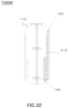
- FIG. 6 schematically shows an example of structure of the serpentine cooling pipe 252.
- Another serpentine cooling pipe 140 and serpentine cooling pipe 150 may have a similar structure as that of the serpentine cooling pipe 252.
- the serpentine cooling pipe 252 extends in the z direction while repeatedly bending.
- the serpentine cooling pipe 252 includes a serpentine portion 610.
- the serpentine portion 610 has a plurality of extending portions 612, and one or more bending portions 614.
- the serpentine portion 610 includes fifteen of the extending portions 612, and fourteen of the bending portions 614.
- the number of the extending portions 612 in a single serpentine portion 610 may be referred to as number of layers.
- the serpentine cooling pipe 252 extends on the x-y plane in the extending portions 612, and bends in the z direction in the bending portions 614.
- each of the plurality of extending portions 612 extends on substantially the same plane.
- the extending portions 612 may not extend on completely the same plane due to manufacturing error, installation error or the like. In such a case, it may be assumed that the extending portions 612 extend on substantially the same plane.
- the extending portions 612 extend on substantially the same plane, it is noted that they are not limited by the above-described example.
- the serpentine cooling pipe 252 is different from a helical cooling pipe. Due to the serpentine cooling pipe 252 extending in a serpentine manner, compared to when the cooling pipe extending helically, surface area per installation area can increase.
- each of the plurality of extending portions 612 extend while curving on the x-y plane.
- a length PL in an extending direction of each of the plurality of extending portions 612 may be the same, and the length in the extending direction of at least two of the extending portions 612 may be different.
- the PL is a length of the extending portions 612 on the x-y plane.
- the PL may be the length of the extending portion 612 in an x-y plane that passes a center of a cross section of the extending portion 612 when the extending portion 612 is cut along a surface substantially perpendicular to the extending direction of the extending portion 612 (in this case, a surface substantially parallel to the z direction.).
- the PL may be less than two-thirds of the length of the inner circumference of the straight body 312.
- the serpentine cooling pipe 252 is different from the coiled cooling pipe described in Japanese Patent Application Publication No. H7-233206 .
- the PL of more than one-half of the number of extending portions 612 may be less than two-thirds of the length of the inner circumference of the straight body 312.
- the above-described PL may be one-half or less of the length of the inner circumference of the straight body 312, may be less than one-half of the length of the inner circumference of the straight body 312, may be one-third or less of the length of the inner circumference of the straight body 312, may be less than one-third of the length of the inner circumference of the straight body 312, may be one-fourth or less of the length of the inner circumference of the straight body 312, may be less than one-fourth of the length of the inner circumference of the straight body 312, may be one-sixth or less of the length of the inner circumference of the straight body 312, and may be less than one-sixth of the length of the inner circumference of the straight body 312.
- the PL of more than two-thirds of the number of extending portions 612 may be less than two-thirds of the length of the inner circumference of the straight body 312.
- the above-described PL may be one-half or less of the length of the inner circumference of the straight body 312, may be less than one-half of the length of the inner circumference of the straight body 312, may be one-third or less of the length of the inner circumference of the straight body 312, may be less than one-third of the length of the inner circumference of the straight body 312, may be one-fourth or less of the length of the inner circumference of the straight body 312, may be less than one-fourth of the length of the inner circumference of the straight body 312, may be one-sixth or less of the length of the inner circumference of the straight body 312, and may be less than one-sixth of the length of the inner circumference of the straight body 312.
- At least one of the plurality of extending portions 612 extends while curving on substantially the same plane.
- at least one of the plurality of extending portions 612 extends along an arc or an elliptical arc virtually arranged on the x-y plane.
- at least one of the plurality of extending portions 612 extends linearly on substantially the same plane.
- two of the plurality of extending portions 612 extend on two substantially parallel planes.
- two adjacent extending portions 612 extend on two substantially parallel planes.
- the serpentine portion 610 that extends like a ladder is obtained.
- two of the plurality of extending portions 612 may extend on two planes that are not parallel.
- two adjacent extending portions 612 extend on two intersecting planes.
- the serpentine portion 610 that extends in a zigzag pattern is obtained.
- each of the one or more bending portions 614 couples ends of two adjacent extending portions 612.
- each of the one or more bending portions 614 includes a portion that bends in the z direction.
- the serpentine portion 610 extends in the z direction while bending.
- a shape of the bending portions 614 is not limited in particular.
- a shape of a cross section (may be referred to as a longitudinal section.) of the bending portion 614 cut along a surface that is parallel to an extending direction of the serpentine cooling pipe 252 and is a surface that passes through a center of the bending portion 614 may have a shape that continuously bends, and may have a shape that is configured by a plurality of straight lines.
- the bending portion 614 may be configured by a portion having the shape that continuously bends, and a portion having a shape configured by one or more straight lines.
- a diameter of a flow channel of the serpentine cooling pipe 252 is not limited in particular, but the above-described diameter is preferably 10 to 200 mm.
- the number of extending portions 612 included in a single serpentine cooling pipe 252 (may be referred to as number of layers.) is not limited in particular, but the above-described number of layers is preferably 2 to 70.
- a size of a distance Pp between two adjacent extending portions 612 (may be referred to as pitch.) is not limited in particular, but the above-described Pp is preferably 60 mm or more. When the Pp is less than 60 mm, polymer scale may tend to adhere.
- the serpentine cooling pipe 252 As an example of when the serpentine cooling pipe 252 extends in the z direction while bending, the example of the serpentine cooling pipe 252 was described. However, the serpentine cooling pipe 252 is not limited to the present embodiment. In another embodiment, the serpentine cooling pipe 252 may extend in the x direction or the y direction while bending.
- the serpentine cooling pipe 252 is not limited to the present embodiment.
- the bending portion 614 may have a first bending portion that bends on the x-y plane, and a second bending portion that bends in the z direction.
- FIG. 7 schematically shows another example of structure of the serpentine cooling pipe 252.
- the serpentine cooling pipe 252 extends in the z direction while bending in a zigzag pattern.
- the serpentine cooling pipe 252 includes a supply pipe 702, an outlet pipe 704, and a serpentine portion 710.
- the serpentine portion 710 includes a plurality of extending portions 712, and one or more bending portions 714.
- the supply pipe 702 allows coolant that is supplied to the serpentine portion 710 to circulate.
- the outlet pipe 704 allows coolant that flows out of the serpentine portion 710 to circulate.
- the serpentine portion 710 extends in the z direction while repeatedly bending.
- the serpentine cooling pipe 252 described in connection to FIG. 7 is different from the serpentine cooling pipe 252 described in connection to FIG. 6 in that the plurality of extending portions 712 are not arranged substantially parallel.
- the serpentine cooling pipe 252 described in connection to FIG. 7 may have a similar configuration to that of the serpentine cooling pipe 252 described in connection to FIG. 6 .
- FIG. 8 schematically shows another example of structure of the serpentine cooling pipe 252.
- the serpentine cooling pipe 252 includes the supply pipe 702, the outlet pipe 704, and a serpentine portion 810.
- the serpentine portion 810 includes a serpentine portion 812, a coupling portion 822, a serpentine portion 814, a coupling portion 824, and a serpentine portion 816.
- the serpentine portion 810 extends in the z direction while repeatedly bending.
- the serpentine portion 812 extends in the x direction while repeatedly bending.
- the serpentine portion 812 extends in a positive x direction.
- the coupling portion 822 couples the serpentine portion 812 and the serpentine portion 814.
- the serpentine portion 814 extends in the x direction while repeatedly bending.
- the serpentine portion 814 extends in a negative x direction.
- the coupling portion 824 couples the serpentine portion 814 and the serpentine portion 816.
- the serpentine portion 816 extends in the x direction while repeatedly bending.
- the serpentine portion 814 extends in the positive x direction.
- each of the serpentine portion 812, the serpentine portion 814, and the serpentine portion 816 may have a similar configuration to that of the serpentine portion 610.
- at least one of the serpentine portion 812, the serpentine portion 814, and the serpentine portion 816 includes a plurality of extending portions, and one or more bending portions.
- each of the plurality of extending portions may extend on the x-y plane, may extend on an x-z plane, and may extend on a y-z plane.
- FIG. 9 schematically shows an example of a main part of a polymerization apparatus 900.
- the polymerization apparatus 900 is different from the polymerization apparatus 100 in that a pitch Pp of the serpentine cooling pipe 140 and a pitch Pp of the serpentine cooling pipe 150 are different.
- the polymerization apparatus 900 may have a similar configuration as that of the polymerization apparatus 100.
- the pitch Pp of the serpentine cooling pipe 140 may be greater than the pitch Pp of the serpentine cooling pipe 150.
- the pitch Pp of the serpentine cooling pipe 140 may be greater than the pitch Pp of the serpentine cooling pipe 150.
- viscosity of slurry flowing inside the reaction vessel 110 is relatively high
- flow of said slurry becomes slow.
- scale tends to adhere to a surface of the serpentine cooling pipe 140, the serpentine cooling pipe 150, the straight body 312 or the like.
- suspension polymerization of vinyl chloride is exemplified.
- discharge flow generated by the agitating blade 124 reaches the serpentine cooling pipe 150 and the straight body 312 while still having sufficient momentum.
- a state of flow nearby the serpentine cooling pipe 140, the serpentine cooling pipe 150, the straight body 312 or the like is improved, and adhering of scale is prevented.
- the pitch Pp of the serpentine cooling pipe 140 may be less than the pitch Pp of the serpentine cooling pipe 150.
- FIG. 10 schematically shows an example of a main part of a polymerization apparatus 1000.
- the polymerization apparatus 1000 is different from the polymerization apparatus 100 in that the number of layers of the serpentine cooling pipe 140 and the number of layers of the serpentine cooling pipe 150 are different.
- the polymerization apparatus 1000 may have a similar configuration as that of the polymerization apparatus 100.
- the polymerization apparatus 1000 may have features of various polymerization apparatus according to another embodiment.
- the number of layers of the serpentine cooling pipe 140 and the serpentine cooling pipe 150 are adjusted so that a position of the upper end of the serpentine cooling pipe 140 is lower than a position of the upper end of the serpentine cooling pipe 150.
- a position of the upper end of the serpentine cooling pipe 140 is lower than a position of the upper end of the serpentine cooling pipe 150.
- the number of layers of the serpentine cooling pipe 140 is preferably adjusted so that the position of the upper end of the serpentine cooling pipe 140 is lower than the agitating blade 124 arranged in an uppermost layer.
- the number of layers of the serpentine cooling pipe 140 and the serpentine cooling pipe 150 may be adjusted so that a position of a lower end of the serpentine cooling pipe 140 is higher than a position of a lower end of the serpentine cooling pipe 150. Further, in another embodiment, the number of layers of the serpentine cooling pipe 140 is adjusted so that the serpentine cooling pipe 140 does not interfere with rotation of the agitating blade 124.
- FIG. 11 schematically shows an example of a main part of a polymerization apparatus 1100.
- the polymerization apparatus 1100 is different from the polymerization apparatus 100 in that it includes a serpentine cooling pipe 1160 between the serpentine cooling pipe 140 and the serpentine cooling pipe 150.
- the polymerization apparatus 1100 may have a similar configuration as that of the polymerization apparatus 100.
- the polymerization apparatus 1100 may have features of various polymerization apparatus according to another embodiment.
- FIG. 12 schematically shows an example of a main part of a polymerization apparatus 1200.
- the polymerization apparatus 1200 is different from the polymerization apparatus 100 in that it includes a serpentine cooling pipe 1252 having a semicircular transverse section instead of the serpentine cooling pipe 252, the serpentine cooling pipe 256, and the serpentine cooling pipe 258.
- the polymerization apparatus 1200 may have a similar configuration as that of the polymerization apparatus 100.
- the polymerization apparatus 1200 may have features of various polymerization apparatus according to another embodiment.
- FIG. 13 schematically shows an example of a main part of a polymerization apparatus 1300.
- the polymerization apparatus 1300 is different from the polymerization apparatus 100 in that it includes a serpentine cooling pipe 1351, a serpentine cooling pipe 1352, a serpentine cooling pipe 1353, a serpentine cooling pipe 1354, a serpentine cooling pipe 1355, and a serpentine cooling pipe 1356 including the extending portions 612 that extend linearly, instead of the serpentine cooling pipe 252, the serpentine cooling pipe 254, the serpentine cooling pipe 256, and the serpentine cooling pipe 258 including the extending portions 612 that extend while curving.
- the polymerization apparatus 1200 is different from the polymerization apparatus 100 in that it includes a baffle 1331, a baffle 1332, a baffle 1333, a baffle 1334, a baffle 1335, and a baffle 1336.
- the polymerization apparatus 1300 may have a similar configuration as that of the polymerization apparatus 100.
- the polymerization apparatus 1300 may have features of various polymerization apparatus according to another embodiment.
- the serpentine cooling pipe 1351, the serpentine cooling pipe 1352, the serpentine cooling pipe 1353, the serpentine cooling pipe 1354, the serpentine cooling pipe 1355, and the serpentine cooling pipe 1355 are arranged at substantially symmetrical positions around the central axis of the reaction vessel 110 on sides of a virtual regular hexagon.
- the baffle 1331, the baffle 1332, the baffle 1333, the baffle 1334, the baffle 1335, and the baffle 1336 are arranged at local maximums of the above-described virtual regular hexagon.
- the number of the serpentine cooling pipes 140 and the number of the serpentine cooling pipes 150 are different.
- the number of the serpentine cooling pipes 140 is less than the number of the serpentine cooling pipes 150.
- the shape of the serpentine cooling pipes 140 and the shape of the serpentine cooling pipes 150 are not similar.
- the extending portions 612 of the serpentine cooling pipes 140 extend while curving, and the extending portions 612 of the serpentine cooling pipes 150 extend linearly.
- the baffle 1331, the baffle 1332, the baffle 1333, the baffle 1334, the baffle 1335, and the baffle 1336 are arranged at local maximums of the virtual regular hexagon.
- the polymerization apparatus 1300 is not limited to the present embodiment.
- At least one of the baffle 1331, the baffle 1332, the baffle 1333, the baffle 1334, the baffle 1335, and the baffle 1336 may be arranged between the above-described virtual regular hexagon and the straight body 312.
- At least one of the baffle 1331, the baffle 1332, the baffle 1333, the baffle 1334, the baffle 1335, and the baffle 1336 may be arranged between the above-described virtual regular hexagon and a virtual circle on which the serpentine cooling pipe 242, the serpentine cooling pipe 244, the serpentine cooling pipe 246, and the serpentine cooling pipe 248 are arranged.
- the number of the serpentine cooling pipes 140 is less than the number of the serpentine cooling pipes 150
- an example of the polymerization apparatus 1300 was described.
- the polymerization apparatus 1300 is not limited to the present embodiment.
- the number of the serpentine cooling pipes 140 may be greater than the number of the serpentine cooling pipes 150.
- the polymerization apparatus 1300 As an example of when the extending portions 612 of the serpentine cooling pipes 140 extend while curving and the extending portions 612 of the serpentine cooling pipes 150 extend linearly, an example of the polymerization apparatus 1300 was described. However, the polymerization apparatus 1300 is not limited to the present embodiment. In another embodiment, the extending portions 612 of the serpentine cooling pipes 140 may extend linearly and the extending portions 612 of the serpentine cooling pipes 150 may extend while curving.
- the polymerization apparatus 1300 is not limited to the present embodiment.
- the diameter of the virtual circle 1403 may be less than the diameter of the virtual circle 1404.
- the diameter of the virtual circle 1403 may be greater than the diameter of the virtual circle 1405.
- FIG. 14 schematically shows an example of a main part of a polymerization apparatus 1400.
- the polymerization apparatus 1400 is different from the polymerization apparatus 100 in that the virtual circle 1403 on which the baffle 232, the baffle 234, the baffle 236, and the baffle 238 are arranged is arranged between the virtual circle 1404 on which the serpentine cooling pipe 242, the serpentine cooling pipe 244, the serpentine cooling pipe 246, and the serpentine cooling pipe 248 are arranged, and the virtual circle 1405 on which the serpentine cooling pipe 252, the serpentine cooling pipe 254, the serpentine cooling pipe 256, and the serpentine cooling pipe 258 are arranged.
- the polymerization apparatus 1400 may have a similar configuration as that of the polymerization apparatus 100. Within a scope not technically inconsistent, the polymerization apparatus 1400 may have features of various polymerization apparatus according to another embodiment.
- FIG. 15 schematically shows an example of a main part of a polymerization apparatus 1500.
- the polymerization apparatus 1500 is different from the polymerization apparatus 1400 in that the baffle 232 is arranged between the serpentine cooling pipe 242 and the serpentine cooling pipe 252, the baffle 234 is arranged between the serpentine cooling pipe 244 and the serpentine cooling pipe 254, the baffle 236 is arranged between the serpentine cooling pipe 246 and the serpentine cooling pipe 256, and the baffle 238 is arranged between the serpentine cooling pipe 248 and the serpentine cooling pipe 258.
- the polymerization apparatus 1500 may have a similar configuration as that of the polymerization apparatus 1400. Within a scope not technically inconsistent, the polymerization apparatus 1500 may have features of various polymerization apparatus according to another embodiment.
- FIG. 16 schematically shows an example of a main part of a polymerization apparatus 1600.
- the polymerization apparatus 1600 is different from the polymerization apparatus 100 in that it does not include the serpentine cooling pipe 244 and the serpentine cooling pipe 248.
- the polymerization apparatus 1600 may have a similar configuration as that of the polymerization apparatus 100.
- the polymerization apparatus 1600 may have features of various polymerization apparatus according to another embodiment.
- a vinyl chloride polymer was produced by using the polymerization apparatus 100 shown in FIG. 2 , deionized water, vinyl chloride monomer, and commercial reagent, and changing a size of the polymerization apparatus 100, as well as structure of the serpentine cooling pipe 140 and the serpentine cooling pipe 150.
- a vinyl chloride polymer was produced by using the polymerization apparatus 1100 shown in FIG. 11 , deionized water, vinyl chloride monomer, and commercial reagent, and changing a size of the polymerization apparatus 1100, as well as structure of the serpentine cooling pipe 140 and the serpentine cooling pipe 150.
- a vinyl chloride polymer was produced by using a polymerization apparatus having the structure described in Japanese Patent Application Publication No. H7-233206 , and commercial reagent. Detail of specifications of the polymerization apparatus 100 or the polymerization apparatus 1100 used in each of the examples 1 to 10 and the comparative example 1 is shown in Table 1, Table 2, or Table 3.
- the number of rotations of the agitation shaft 122 of the polymerization apparatus 100 or the polymerization apparatus 1100 was set based on a relationship between the number of rotations of the agitation shaft 122 in a pilot plant and quality including similar internal structures to those of each example.
- the number of rotations of the agitation shaft 122 of the polymerization apparatus 100 or the polymerization apparatus 1100 was set so that a planned value of agitation energy in the pilot plant and a planned value of agitation energy in the polymerization apparatus 100 or the polymerization apparatus 1100 were substantially identical.
- polymerization temperature was set based on a target K-value of the polymer.
- the polymerization temperature in each of the examples 1 to 10 and the comparative example 1 was the same as a polymerization temperature in the pilot plant including similar internal structures as each of the examples. Detail of polymerization conditions in each of the examples 1 to 10 and the comparative example 1 is shown in Table 4, Table 5, or Table 6.
- volumetric flow rate and temperature of coolant in an entrance side of the baffle 130, the serpentine cooling pipe 140, the serpentine cooling pipe 150, and the jacket 170 were the same.
- polymerization tests were performed by changing a total value of surface area of the serpentine cooling pipe 140 and the serpentine cooling pipe 150.
- a proportion of heat removal amount by the baffle 130 in relation to a gross calorific value was approximately 12 to 17%.
- a proportion of heat removal amount by serpentine cooling pipe 140 and the serpentine cooling pipe 150 in relation to the gross calorific value was approximately 22 to 44%.
- a proportion of heat removal amount by the jacket 170 in relation to the gross calorific value was approximately 25 to 34%.
- a proportion of heat removal amount by the reflux condenser 180 in relation to the gross calorific value was approximately 19 to 27%.
- the polymerization test was repeated. After a predetermined number of times of the polymerization test ended, the surface of the serpentine cooling pipe 140 and the serpentine cooling pipe 150 was observed visually, and presence or absence of scale adhesion was confirmed. When scale adhesion was not confirmed, it shows that even when performing the polymerization test repeatedly, the internal structures arranged inside the reaction vessel 110 did not cause scale adhesion.
- EXAMPLE 9 EXAMPLE 10 COMPARATIVE EXAMPLE 1 SERPENTINE COOLING PIPE 150 DIAMETER (OUTER DIAMETER) [mm] 90 90 60 SHAPE OF EXTENDING PORTION [-] ARC SHAPE ARC SHAPE RING SHAPE NUMBER OF LAYERS [-] 18 18 12 PITCH Pp [mm] 400 200 400 DISTANCE FROM CENTRAL AXIS [mm] 2,225 2,225 1,350 SERPENTINE COOLING PIPE 140 DIAMETER (OUTER DIAMETER) [mm] 90 90 60 SHAPE OF EXTENDING PORTION [-] ARC SHAPE ARC SHAPE RING SHAPE NUMBER OF LAYERS [-] 18 18 12 PITCH Pp [mm] 400 200 400 DISTANCE FROM CENTRAL AXIS [mm] 1,975 1,975 1,100 SERPENTINE COOLING PIPE 1160 DIAMETER (OUTER DIAMETER) [mm] - 90 - SHAPE
- EXAMPLE 9 COMPARATIVE EXAMPLE 1 RAW MATERIAL OR THE LIKE DEIONIZED WATER [kg] 86,400 86,000 34,900 VINYL CHLORIDE MONOMER [kg] 77,700 77,400 31,400 PARTIALLY SAPONIFIED POLYVINYL ALCOHOL [kg] 25.6 25.5 103 HYDROXYPROPYLMETHYLCELLULOSE [kg] 11.0 1 0.9 4.4 POLYMERIZATION INITIATOR A [kg] 57.0 66.3 32.7 POLYMERIZATION INITIATOR B [kg] 8.2 81 3.3 POLYMERIZATION INITIATOR C [kg] 12.9 150 7.4 POLYMERIZATION CONDITIONS TARGET K-VALUE [-] 65.1 65.1 65.1 EVALUATION ITEMS MEASURED K-VALUE [-] 65.1 651 651 POLYMERIZATION TIME [min] 180 160 130 SCALE ADHESION STATE [-] NO ADHESION
- Example 1 Detail of the specifications of the polymerization apparatus 100 used in example 1 is shown in Table 1.
- the reaction vessel 110 with an internal capacity of 80 m 3 was prepared.
- a diameter of the straight body 312 of the reaction vessel 110 was 3600 mm, and a height of the straight body 312 was 6800 mm.
- each of the four serpentine cooling pipes 140 formed of an austenitic stainless steel cylindrical pipe having an outer diameter of 90 mm were arranged.
- a distance between a center of each of the four serpentine cooling pipes 140 and the central axis of the reaction vessel 110 was 1360 mm.
- the four serpentine cooling pipes 140 were arranged at symmetrical positions centered around the central axis of the reaction vessel 110.
- the number of layers of each of the four serpentine cooling pipes 140 was twelve layers. That is, each of the four serpentine cooling pipes 140 included twelve extending portions 612.
- pitch Pp. was 400 mm.
- serpentine cooling pipes 150 formed of an austenitic stainless steel cylindrical pipe having an outer diameter of 90 mm were installed inside the reaction vessel 110.
- the four serpentine cooling pipes 150 were arranged at symmetrical positions centered around the central axis of the reaction vessel 110.
- the number of layers of each of the four serpentine cooling pipes 150 was twelve layers.
- the pitch Pp was 400 mm.
- a proportion of the total value of the surface area of the serpentine cooling pipe 140 and the serpentine cooling pipe 150 in relation to the internal capacity of the reaction vessel 110 was 0.645 m 2 /m 3 .
- the number of rotations of the agitation shaft 122 was decided.
- the number of rotations of the agitation shaft 122 was decided so that the agitation energy described above is 80 to 200 kgf ⁇ m/s ⁇ m 3 .
- the number of rotations of the agitation shaft 122 was decided so that a target quality can be obtained with a polymerization temperature at which the K-value of the produced vinyl chloride resin is 65.1.
- the reduced viscosity (K-value) of a vinyl chloride resin was measured according to JIS K 7367-2.
- the shape and blade number of the agitating blade 124, the installation position of the agitating blade 124, the installation number, and the installation interval Pi were made to be similar to the agitating blade 124 used in the pilot plant, and scale-up was performed. Scale-up of dimensions of the agitating blade 124 was performed so that a ratio of the dimensions of the agitating blade 124 in relation to dimensions of the reaction vessel 110 used in the pilot plant is constant. Similarly, the size and arrangement of the baffle 232, the baffle 234, the baffle 236, and the baffle 238 were decided.
- an isoparaffin solution containing di-2-ethylhexyl peroxydicarbonate was used as the polymerization initiator A. An added amount of the di-2-ethylhexyl peroxydicarbonate was 34.4 kg.
- an isoparaffin solution including t-butylperoxyneodecanate was used as the polymerization initiator B. An isoparaffin solution including t-butylperoxyneodecanate was used. An added amount of the t-butylperoxyneodecanate was 3.3 kg.
- an isoparaffin solution including cumylperoxyneodecanate was used as the polymerization initiator C. An added amount of the cumylperoxyneodecanate was 7.7 kg.
- polymerization was started by passing hot water into the jacket 170, and increasing a temperature of the mixed solution inside the reaction vessel 110 to 57°C.
- a temperature of the mixed solution inside the reaction vessel 110 reached 57°C
- passing of cooling water into the baffle 130, the serpentine cooling pipe 140, the serpentine cooling pipe 150, and the jacket 170 was started.
- the reflux condenser 180 was operated.
- the above-described polymerization test was set as one batch, and the above-described polymerization test was performed repeatedly.
- a vinyl chloride polymer was synthesized by using the polymerization apparatus 100 having the specifications shown in Table 1 and by a similar procedure as that of example 1.
- the target K-value was 65.1.
- Detail of reaction conditions in each of the examples is shown in Table 4. Measurement results of the K-value and the polymerization time, as well as confirmation results of the adhesion state of scale are shown in Table 4.
- a vinyl chloride polymer was synthesized by using the polymerization apparatus 100 or the polymerization apparatus 1100 having the specifications shown in Table 2 and by a similar procedure as that of example 1.
- the target K-value was 65.1.
- the target K-value was 58.6.
- Detail of reaction conditions in each of the examples are shown in Table 5. Measurement results of the K-value and the polymerization time, as well as confirmation results of the adhesion state of scale are shown in Table 5.
- a vinyl chloride polymer was synthesized by using the polymerization apparatus 100 or the polymerization apparatus 1100 having the specifications shown in Table 3 and by a similar procedure as that of example 1.
- the target K-value was 65.1.
- Detail of reaction conditions in each of the examples is shown in Table 6. Measurement results of the K-value and the polymerization time, as well as confirmation results of the adhesion state of scale are shown in Table 6.
- a vinyl chloride polymer was synthesized by using the polymerization apparatus shown in Patent Document 2 by a similar procedure as that of example 1.
- the target K-value was 65.1.
- a coiled cooling pipe was used instead of the serpentine cooling pipe 140.
- An austenitic stainless steel cylindrical pipe having an outer diameter of 60 mm was used as the cooling pipe.
- a distance between a center of the coiled cooling pipe and the center of the reaction vessel 110 was 1100 mm.
- the number of layers of coil was twelve layers, and a pitch of the coil was 400 mm.
- a coiled cooling pipe was used instead of the serpentine cooling pipe 150.
- An austenitic stainless steel cylindrical pipe having an outer diameter of 60 mm was used as the cooling pipe.
- a distance between a center of the coiled cooling pipe and the center of the reaction vessel 110 was 1350 mm.
- the number of layers of coil was twelve layers, and a pitch of the coil was 400 mm.
- the vinyl chloride polymer having the K-value of 65.1 was obtained in examples 1 to 7 and 9 to 10.
- the polymerization time was two to three hours which was the same degree as the planned value.
- the vinyl chloride polymer having the K-value of 58.6 was obtained.
- the polymerization time was 150 minutes which was the same degree as the planned value.
- the polymerization apparatus has sufficient cooling power. It is shown by each of the examples that size increase of the reaction vessel and shortening of the polymerization time are compatible.
- the vinyl chloride polymer having the K-value of 65.1 was obtained.
- the polymerization time was two hours and ten minutes which was the same degree as the planned value.
- 100 polymerization apparatus, 110: reaction vessel, 120: agitator, 122: agitation shaft, 124: agitating blade, 126: power mechanism, 130: baffle, 132: body, 134: support, 140: serpentine cooling pipe, 150: serpentine cooling pipe, 170: jacket, 172: flow channel, 180: reflux condenser, 182: flow channel, 232: baffle, 234: baffle, 236: baffle, 238: baffle, 242: serpentine cooling pipe, 244: serpentine cooling pipe, 246: serpentine cooling pipe, 248: serpentine cooling pipe, 252: serpentine cooling pipe, 254: serpentine cooling pipe, 256: serpentine cooling pipe, 258: serpentine cooling pipe, 312: straight body, 314: first panel, 316: second panel, 318: pedestal, 332: coolant supplying pipe, 334: coolant returning pipe, 342: coupling portion, 344: coupling portion, 346: coupling portion, 510: inner pipe, 512: inlet,
Landscapes
- Chemical & Material Sciences (AREA)
- Chemical Kinetics & Catalysis (AREA)
- Organic Chemistry (AREA)
- Health & Medical Sciences (AREA)
- Medicinal Chemistry (AREA)
- Polymers & Plastics (AREA)
- Polymerisation Methods In General (AREA)
- Accessories For Mixers (AREA)
- Physical Or Chemical Processes And Apparatus (AREA)
- Mixers Of The Rotary Stirring Type (AREA)
Abstract
Description
- The present invention relates to a reaction apparatus, and a method for producing vinyl-based polymer.
-
Patent document 1 discloses a polymerization apparatus including a baffle and a serpentine pipe that can circulate a coolant inside. - Patent document 2 discloses a polymerization apparatus including a baffle and a coiled cooling pipe that can circulate a coolant inside.
- Patent document 3 discloses a resin synthesizing apparatus including a baffle that can circulate a heat carrier inside, and an agitating means including a helical ribbon wing and an anker wing.
-
- Patent document 1:
Japanese Patent Application Publication No. H7-233202 - Patent document 2:
Japanese Patent Application Publication No. H7-233206 - Patent document 3:
Japanese Patent Application Publication No. 2013-151621 - In a first aspect of the present invention, a reaction apparatus is provided. For example, the above-described reaction apparatus includes a reactor having a tubular shape. For example, the above-described reaction apparatus includes a plurality of first cooling pipes for circulating a coolant. In the above-described reaction apparatus, for example, the plurality of first cooling pipes are arranged inside the reactor. In the above-described reaction apparatus, for example, each of the plurality of first cooling pipes has a serpentine portion that extends while repeatedly bending. In the above-described reaction apparatus, for example, the serpentine portion includes a plurality of extending portions that extend linearly or extend while curving. In the above-described reaction apparatus, for example, the serpentine portion includes a plurality of bending portions which couple ends of two adjacent extending portions, among the plurality of extending portions. In the above-described reaction apparatus, for example, at least two of the plurality of first cooling pipes have different distances from an inner wall surface of the reactor. In the above-described reaction apparatus, for example, among the at least two of the first cooling pipes, a length of at least one part of the plurality of extending portions included in the first cooling pipe having a smallest distance from the inner wall surface of the reactor is less than two-thirds of a length of a circumference of the inner wall surface.
- In any of the above-described reaction apparatus, among the plurality of extending portions included in the first cooling pipe having the smallest distance from the inner wall surface of the reactor, a length of more than one-half of a number of the extending portions may be less than two-thirds of the length of the circumference of the inner wall surface. In any of the above-described reaction apparatus, a ratio of a surface area of the serpentine portion in relation to an internal capacity of the reactor may be 0.1 to 0.9 m2/m3. In any of the above-described reaction apparatus, the ratio of the surface area of the serpentine portion in relation to the internal capacity of the reactor may be 0.5 to 0.7 m2/m3. In the above-described reaction apparatus, an internal capacity of the reaction vessel may be 40 to 300 m3.
- Any of the above-described reaction apparatus may include a plurality of baffles extending substantially parallel to an extending direction of the reactor. In any of the above-described reaction apparatus, at least one part of each of the plurality of baffles may be arranged in contact with the inner wall surface of the reactor. In any of the above-described reaction apparatus, one part of the plurality of first cooling pipes may be arranged at a position that is between two baffles included in the plurality of baffles, and spaced apart from the inner wall surface of the reactor. In any of the above-described reaction apparatus, at least one of the plurality of baffles may include a second cooling pipe for circulating a coolant.
- Any of the above-described reaction apparatus, may include a reflux condenser. In any of the above-described reaction apparatus, the reflux condenser may include a third cooling pipe for circulating a coolant. Any of the above-described reaction apparatus may include a jacket. In any of the above-described reaction apparatus, the jacket may include a third cooling pipe for circulating a coolant. Any of the above-described reaction apparatus may be used for application of suspension polymerization.
- In a second aspect of the present invention, a method for producing vinyl-based polymer is provided. For example, the above-described method for producing includes polymerizing a vinyl-based monomer by using the reaction apparatus according to the first aspect to produce the vinyl-based polymer.
- The above-described overview of the invention is not an exhaustive list of all necessary features of the present invention. Subcombinations of these features can also be an invention.
-
-
FIG. 1 shows a schematic cross-sectional view of an example of apolymerization apparatus 100. -
FIG. 2 schematically shows an example of internal structures arranged inside areaction vessel 110. -
FIG. 3 shows a schematic cross-sectional view of an example of thereaction vessel 110. -
FIG. 4 shows a schematic plan view of an example of thereaction vessel 110. -
FIG. 5 schematically shows an example of internal structure of abaffle 232. -
FIG. 6 schematically shows an example of structure of aserpentine cooling pipe 252. -
FIG. 7 schematically shows another example of structure of theserpentine cooling pipe 252. -
FIG. 8 schematically shows another example of structure of theserpentine cooling pipe 252. -
FIG. 9 schematically shows an example of a main part of apolymerization apparatus 900. -
FIG. 10 schematically shows an example of a main part of apolymerization apparatus 1000. -
FIG. 11 schematically shows an example of a main part of apolymerization apparatus 1100. -
FIG. 12 schematically shows an example of a main part of apolymerization apparatus 1200. -
FIG. 13 schematically shows an example of a main part of apolymerization apparatus 1300. -
FIG. 14 schematically shows an example of a main part of apolymerization apparatus 1400. -
FIG. 15 schematically shows an example of a main part of apolymerization apparatus 1500. -
FIG. 16 schematically shows an example of a main part of apolymerization apparatus 1600. - Hereinafter, the present invention will be described through embodiments of the invention, but the following embodiments do not limit the invention according to the scope of the claims. In addition, not all of the combinations of features described in the embodiments are imperative to the solving means of the invention. In the present embodiments, when a numeric range is written as "A to B", said writing means A or more and B or less.
- An example of a
polymerization apparatus 100 is described in detail by usingFIG. 1 ,FIG. 2 ,FIG. 3 , andFIG. 4 . Thepolymerization apparatus 100 is used, for example, for producing a polymer. Thepolymerization apparatus 100 may be used for application of suspension polymerization. - More specifically, the
polymerization apparatus 100 is used for producing a vinyl-based polymer. As a method for producing the vinyl-based polymer, a method having a step for polymerizing a vinyl-based monomer by using thepolymerization apparatus 100 to produce a vinyl-based polymer is exemplified. The above-described method for producing the vinyl-based polymer includes, for example, a step for storing raw material, including a vinyl-based monomer, in a reactor arranged in thepolymerization apparatus 100. The above-described method for producing the vinyl-based polymer includes, for example, a step for starting a polymerization reaction of the above-described vinyl-based monomer and producing a vinyl-based polymer. -
FIG. 1 shows a schematic cross-sectional view of an example of thepolymerization apparatus 100. In the present embodiment, thepolymerization apparatus 100 includes areaction vessel 110, anagitator 120, one or a plurality of (may be referred to simply as one or more) baffles 130, one or moreserpentine cooling pipes 140, one or moreserpentine cooling pipes 150, ajacket 170, and areflux condenser 180. In the present embodiment, theagitator 120 includes anagitation shaft 122, an agitatingblade 124, and apower mechanism 126. In the present embodiment, thebaffle 130 includes abody 132 and one ormore supports 134. In the present embodiment, thejacket 170 includes aflow channel 172 for a heat carrier. In the present embodiment, thereflux condenser 180 includes aflow channel 182 for a heat carrier. - In the present embodiment, the
agitation shaft 122 and the agitatingblade 124 are arranged inside thereaction vessel 110. In the present embodiment, each of the one ormore baffles 130 is arranged inside thereaction vessel 110. In the present embodiment, each of the one or moreserpentine cooling pipes 140 is arranged inside thereaction vessel 110. In the present embodiment, each of the one or moreserpentine cooling pipes 150 is arranged inside thereaction vessel 110. - In the present embodiment, the
power mechanism 126 is arranged outside thereaction vessel 110. In the present embodiment, thejacket 170 is arranged outside thereaction vessel 110. In the present embodiment, thereflux condenser 180 is arranged outside thereaction vessel 110. - In the present embodiment, the
serpentine cooling pipe 140 and theserpentine cooling pipe 150 are arranged so that their distances from an inner surface of thereaction vessel 110 are different. Specifically, theserpentine cooling pipe 150 is arranged at a position closer to a side surface of thereaction vessel 110 than theserpentine cooling pipe 140. In this case, a distance L2 from theserpentine cooling pipe 140 to the side surface of thereaction vessel 110 is greater than a distance L1 from theserpentine cooling pipe 150 to the side surface of thereaction vessel 110. - The distance L2 from the
serpentine cooling pipe 140 to the side surface of thereaction vessel 110 may be a minimum value of a distance from a center of a cross section of theserpentine cooling pipe 140 to the side surface of thereaction vessel 110. The distance L1 from theserpentine cooling pipe 150 to the side surface of thereaction vessel 110 may be a minimum value of a distance from a center of a cross section of theserpentine cooling pipe 150 to the side surface of thereaction vessel 110. For example, when theserpentine cooling pipe 140 or theserpentine cooling pipe 150 is a circular pipe, the cross section of theserpentine cooling pipe 140 or theserpentine cooling pipe 150 is circular, and the center of the cross section of theserpentine cooling pipe 140 or theserpentine cooling pipe 150 is the center of said circle. - Thus, according to the present embodiment, heat inside the
reaction vessel 110 can be removed efficiently. For example, when thepolymerization apparatus 100 is used for producing a polymer, thepolymerization apparatus 100 can efficiently remove heat of reaction generated in a polymerization reaction. - In particular, in suspension polymerization of a monomer mixture mainly composed of a vinyl chloride-based monomer or a vinyl chloride-based chemical compound (together both may be referred to as a vinyl chloride-based monomer.), when internal structures such as a cooling coil or a draft tube or the like is arranged inside the
reaction vessel 110, a power requirement of theagitator 120 increases. Shape, size, and installation position of the above-described internal structures affect mixing performance of thepolymerization apparatus 100. Therefore, depending on the internal structures, a portion of slow flow can be generated inside thereaction vessel 110. When the portion of slow flow is generated inside thereaction vessel 110, temperature inside thereaction vessel 110 becomes nonuniform. As a result, particle size and/or degree of polymerization of the produced polymer tends to be nonuniform, and polymer scale tends to adhere to an inner wall or surfaces of the internal structures of thereaction vessel 110. The above-described scale can cause a fish eye that impairs quality of a molded product using a polymer. - In conditions under which heat removal efficiency is the same, size increase of the
reaction vessel 110 and shortening of reaction time are in a tradeoff relationship. Therefore, in order to increase the size of thereaction vessel 110 while shortening the reaction time, it is desirable to increase the heat removal efficiency of thepolymerization apparatus 100. - As a method for increasing the heat removal efficiency of the
polymerization apparatus 100, decreasing temperature of a coolant can be conceived. However, when the temperature of the coolant is decreased, production cost of a polymer increases. As another method for increasing the heat removal efficiency of thepolymerization apparatus 100, increasing heat removal amount by thejacket 170 or thereflux condenser 180 can be conceived. In particular, in a large-sized polymerization vessel of 40 m3 or more, since the heat removal amount by thejacket 170 alone is insufficient, greatly increasing the heat removal amount by thereflux condenser 180 can be conceived. However, when heat removal load of thereflux condenser 180 is increased, foaming amount of a polymer slurry inside thereaction vessel 110 can increase. When the foaming amount of the polymer slurry increases, heat removal capacity of thereflux condenser 180 may decrease, and polymer scale may adhere inside thereflux condenser 180. - For example, when a polymerization vessel capacity is increased in size by using the polymerization apparatus described in
Patent document 1, if a conduction area of a serpentine pipe is insufficient, there is a chance that shortening reaction time while maintaining product quality becomes difficult. On the other hand, in the polymerization apparatus described in Patent document 2, conduction area can be increased by a relatively simple structure. However, due to the structure of the apparatus, a baffle and a coiled cooling pipe cannot be arranged on substantially the same circumference. Therefore, a proportion of a region where the coiled cooling pipe can be installed in relation to a capacity of the apparatus is relatively small. When a polymerization vessel capacity is increased in size by using the polymerization apparatus described in Patent document 2, if a distance between coiled cooling pipes is decreased to increase conduction area, there is a chance that mixing performance of the polymerization apparatus decreases. In addition, when scale or a lump of reactant is generated on a surface of the coiled cooling pipe due to disturbances or the like, it is difficult to sufficiently remove the above-described scale or the like because working inside the can becomes complicated. - Meanwhile, according to the
polymerization apparatus 100 according to the present embodiment, theserpentine cooling pipe 140 and theserpentine cooling pipe 150 are arranged so that their distances from the inner surface of thereaction vessel 110 are different. Thus, conduction area can be increased by using a relatively simple structure having a small effect on mixing performance of thepolymerization apparatus 100. According to thepolymerization apparatus 100 according to the present embodiment, degree of freedom relating to installation positions of theserpentine cooling pipe 140 and theserpentine cooling pipe 150 is high. For example, at least one of the one or moreserpentine cooling pipes 140 or the one or moreserpentine cooling pipes 150, and thebaffle 130 can be arranged on substantially the same circumference. Thus, the conduction area of the entire apparatus can be increased while making the effect on the mixing performance of thepolymerization apparatus 100 by theserpentine cooling pipe 150 smaller. - In the present embodiment, the
reaction vessel 110 stores material of a synthesizing reaction. When thepolymerization apparatus 100 is used for producing a polymer, for example, polymerization is started after a polymerizable monomer, a polymerization initiator, an aqueous media, a dispersing aid or the like is prepared inside thereaction vessel 110. For example, any surfactant can be used as the dispersing aid. - For example, the
reaction vessel 110 has a tubular shape. Thereaction vessel 110 may have a cylindrical shape, and may have a rectangular tubular shape. For example, thereaction vessel 110 is installed so that an extending direction of the reaction vessel 110 (z direction in the figure.) is a vertical direction. - As a shape of a cross section (may be referred to as a transverse section) of the
reaction vessel 110 cut along a surface perpendicular to the extending direction of the reaction vessel 110 (x-y plane in the figure.), a circular, oval, or polygonal shape or the like is exemplified. The shape of the transverse section of thereaction vessel 110 may be a shape that can be considered substantially as a circular, oval, or polygonal shape. - An internal capacity of the
reaction vessel 110 is not limited in particular, but the internal capacity of thereaction vessel 110 is, for example, 1 to 300 m3. A lower limit value of the internal capacity of thereaction vessel 110 may be 40 m3, may be 80 m3, may be 100 m3, may be 120 m3, may be 130 m3, may be 150 m3, may be 200 m3, and may be 250 m3. An upper limit value of the internal capacity of thereaction vessel 110 may be 300 m3 or more. The upper limit value of the internal capacity of thereaction vessel 110 may be 350 m3, and may be 400 m3. The greater the internal capacity of thereaction vessel 110, improvement of cooling power according to the present embodiment can be done more advantageously. - The internal capacity of the
reaction vessel 110 is defined as a capacity when thereaction vessel 110 stores liquid up to a predetermined upper limit position of thereaction vessel 110. The internal capacity of thereaction vessel 110 is, for example, a volume inside thereaction vessel 110 when internal structures such as an agitating shaft, wings, baffle, coil or the like are not arranged inside thereaction vessel 110. - As described above, size increase of the
reaction vessel 110 and shortening of reaction time are in a tradeoff relationship. When the internal capacity of thereaction vessel 110 becomes 40 m3 or more, heat removal efficiency of thepolymerization apparatus 100 tends to be insufficient, and it is difficult to shorten the reaction time while increasing the size of thereaction vessel 110. In particular, when the internal capacity of thereaction vessel 110 is 80 m3 or more, an effect of thepolymerization apparatus 100 according to the present embodiment is more pronounced. Detail of thereaction vessel 110 is described below. - In the present embodiment, the
agitator 120 agitates liquid stored inside thereaction vessel 110. In the present embodiment, theagitation shaft 122 holds the agitatingblade 124 and rotates the agitatingblade 124. In the present embodiment, the agitatingblade 124 is attached to theagitation shaft 122 and agitates liquid stored inside thereaction vessel 110. - A shape of the agitating
blade 124 is not limited in particular, but a Pfaudler blade, blue margin blade, paddle blade, inclined paddle blade, turbine blade, propeller blade, and combinations thereof are exemplified as the shape of the agitatingblade 124. Thus, by rotation of theagitation shaft 122, a discharge flow from theagitation shaft 122 is generated radially toward an outer circumference. A quantity of blades that the agitatingblade 124 includes is not limited in particular, but 2 to 6 blades are exemplified as the quantity of the above-described blades. An installation position and installation number of the agitatingblade 124 are not limited in particular, but the agitatingblade 124 is preferably installed in multiple layers. As a number of layers of the agitatingblade 124, 2 to 6 layers are exemplified. - In the present embodiment, the
power mechanism 126 rotates theagitation shaft 122. For example, thepower mechanism 126 includes a power portion (not shown.) that generates power and a power transmission portion (not shown.) that transmits power generated by the power portion to theagitation shaft 122. As the power portion, an electric motor is exemplified. As the power transmission portion, a reduction gear is exemplified. - A number of rotations of the
agitation shaft 122, as well as the shape, the size, the quantity of blades, the installation position, the installation number, and an installation interval Pi of the agitatingblade 124 are decided appropriately according to an application of thepolymerization apparatus 100. The number of rotations of theagitation shaft 122, as well as the shape, the size, the quantity of blades, the installation position, the installation number, and the installation interval Pi of the agitatingblade 124 are, for example, decided in consideration of the internal capacity of thereaction vessel 110, the shape of thereaction vessel 110, the internal structures arranged inside thereaction vessel 110, a configuration of the heat removal means, heat removal capacity, and composition of raw material prepared for polymerization. - For example, when the
polymerization apparatus 100 is used for application of suspension polymerization, the number of rotations of theagitation shaft 122 is decided so that agitation energy applied to content (aqueous suspension mixture in this case.) is 80 to 200 kgf·m/s·m3. The "agitation energy" applied to the content is defined as net energy required for agitating per unit amount (may be referred to as unit internal capacity.) of the content that is obtained by subtracting various types of energy loss B such as motor efficiency, conduction loss, mechanical loss or the like from energy A that is loaded on an agitator drive motor arranged in thepower mechanism 126, during operation of thepolymerization apparatus 100. As the above-described unit amount, unit mass, unit volume or the like are exemplified. For example, if a volume of the content is C, the agitation energy is calculated by the followingExpression 1.
- The energy loaded on the agitator drive motor, for example, can be measured electrically by using a measurement device such as a watt meter or the like. The agitation energy can be adjusted easily by changing the number of rotations of the
agitation shaft 122. - The number of rotations of the
agitation shaft 122 in thepolymerization apparatus 100, for example, is decided based on a polymerization test performed in advance in a pilot plant. Generally, scale-up from the pilot plant to thepolymerization apparatus 100 is performed so that an agitation state of thepolymerization apparatus 100 and an agitation state of the pilot plant are substantially identical. For example, in the pilot plant and thepolymerization apparatus 100, a shape, size, and arrangement of each internal structure is decided so that the shape and size of thereaction vessel 110, and the shape, size, and arrangement of the internal structures such as the agitatingblade 124, thebaffle 130, theserpentine cooling pipe 140, theserpentine cooling pipe 150 or the like are similar. - According to one embodiment, the number of rotations of the
agitation shaft 122 in thepolymerization apparatus 100 can be decided so that the agitation energy in thepolymerization apparatus 100 and the agitation energy in the pilot plant are substantially the same. As described above, the agitation energy is, for example, calculated as "(A-B)/C". As an approach for deciding the number of rotations of theagitation shaft 122 based on the agitation energy, any well-known approach can be adopted. - The number of rotations of the
agitation shaft 122 in the pilot plant is, for example, decided by the following procedure. For example, a relationship between the number of rotations of theagitation shaft 122 in the pilot plant and quality of a polymer is obtained by a polymerization test using the pilot plant. Thus, the number of rotations of theagitation shaft 122 with which a polymer of desired quality can be obtained is decided. The above-described quality is not limited in particular, but as the above-described quality, for example, particle size is exemplified. - Specifically, in the polymerization test using the pilot plant, a polymerization temperature is set according to a desired reduced viscosity of the polymer (may be referred to as K-value.). The polymerization temperature and an average degree of polymerization of a polymer are correlated, and the K-value of the polymer is used widely as an indicator expressing the average degree of polymerization of the polymer.
- In the polymerization test using the pilot plant, a polymerization time is decided according to heat removal capacity of the pilot plant. For example, the polymerization time is decided according to (i) preparation amount of a monomer that is a starting material, (ii) input amount of a polymerization initiator, and (iii) the heat removal capacity of the pilot plant, so that a calorific value of a reaction does not exceed the heat removal capacity of the pilot plant.
- In this manner, when the polymerization time is set so that the pilot plant has sufficient heat removal capacity, a polymer having a desired average degree of polymerization can be generated by setting the polymerization temperature according to a target K-value. For example, a polymerization test is performed for each of a plurality of conditions in which the polymerization temperature and the polymerization time is the same, and the number of rotations of the
agitation shaft 122 is different. - Based on a plurality of test results in which the number of rotations of the
agitation shaft 122 is different, the relationship between the number of rotations of theagitation shaft 122 in the pilot plant and the quality of the polymer is obtained. Thus, when a target value of the quality of the polymer is decided, the number of rotations of theagitation shaft 122 by which a polymer of the desired quality can be decided. - When the polymerization time is set so that the pilot plant has sufficient heat removal capacity, a polymer having the desired average degree of polymerization can be generated by setting the polymerization temperature according to the target K-value. On the other hand, when the heat removal capacity of the pilot plant in relation to the set polymerization time is poor, the polymerization temperature rises due to heat generation by a polymerization reaction. As described above, a correlation exists between the polymerization temperature and the average degree of polymerization of the generated polymer. Therefore, when the polymerization temperature rises, the error between the K-value of the generated polymer and the target K-value increases. Depending on how the polymerization temperature rises, control of the reaction can become impossible.
- In this manner, the K-value of the generated polymer can be adopted as an indicator that relates to heat removal capacity of the
polymerization apparatus 100. For example, when a polymer is generated by using thepolymerization apparatus 100, when a target K-value for a set polymerization time is obtained, thepolymerization apparatus 100 can be determined to have sufficient heat removal capacity. - As described above, scale-up from the pilot plant to the
polymerization apparatus 100 can be performed so that the agitation state of thepolymerization apparatus 100 and the agitation state of the pilot plant are substantially identical. For example, when a ratio of size of each internal structure arranged inside thereaction vessel 110 in relation to an inner diameter and/or straight body height of thereaction vessel 110 in a desiredpolymerization apparatus 100, and a ratio of the size of each internal structure in the pilot plant in relation to an inner diameter and/or straight body height of the reaction vessel of the pilot plant are substantially identical, when the agitation energy in thepolymerization apparatus 100 and the agitation energy in the pilot plant are substantially the same, the agitation state of the scaled uppolymerization apparatus 100 and the agitation state of the pilot plant are substantially identical. - For example, a size of the
baffle 130 in the desiredpolymerization apparatus 100 is decided so that ratios of a length of thebaffle 130 in its extending direction (up and down direction in the figure) in relation to the straight body height of thereaction vessel 110 between the pilot plant and the desiredpolymerization apparatus 100 are substantially the same. The size of thebaffle 130 in the desiredpolymerization apparatus 100 is decided so that the ratios of a length of thebaffle 130 in a direction that is substantially perpendicular to its extending direction (left and right directions in the figure) in relation to a diameter inside the reaction vessel 110 (may be referred to as inner diameter.) between the pilot plant and the desiredpolymerization apparatus 100 are substantially the same. The number of thebaffle 130 and its arrangement in the desiredpolymerization apparatus 100 are decided so that the number of thebaffle 130 and its arrangement are substantially the same between the pilot plant and the desiredpolymerization apparatus 100. It is similar for another structure (for example, the agitatingblade 124, theserpentine cooling pipe 140, theserpentine cooling pipe 150 or the like.). - As described above, when the target value of the quality of the polymer in the scaled up
polymerization apparatus 100 is decided, the number of rotations of theagitation shaft 122 in the scaled uppolymerization apparatus 100 can be decided based on the relationship between the number of rotations of theagitation shaft 122 in the pilot plant and the quality of the polymer described above. Specifically, first, the number of rotations of theagitation shaft 122 in the pilot plant is decided based on (i) the target value of the quality of the polymer in thepolymerization apparatus 100, and (ii) the relationship between the number of rotations of theagitation shaft 122 in the pilot plant and the quality of the polymer. Then, the number of rotations of theagitation shaft 122 in thepolymerization apparatus 100 is decided so that the agitation energy in thepolymerization apparatus 100 and the agitation energy in the pilot plant are substantially the same. - Thus, the number of rotations of the
agitation shaft 122 of the desiredpolymerization apparatus 100 can be decided in consideration of (i) the shape, size, quantity of blades, installation position, installation number, and installation interval Pi of the agitatingblade 124, as well as (ii) the internal capacity of thereaction vessel 110, the shape of thereaction vessel 110, and the internal structures or the like arranged inside thereaction vessel 110 of the desiredpolymerization apparatus 100, without strictly measuring the above-described agitation energy per unit internal capacity (kgf·m/s·m3). The number of rotations of theagitation shaft 122 in the desiredpolymerization apparatus 100 may be decided based on a simulation result of a polymerization test. - In the present embodiment, the
baffle 130 improves the mixing performance of thepolymerization apparatus 100. For example, thebaffle 130 improves mixing performance of the up and down direction inside thereaction vessel 110. Installation position of thebaffle 130 is not limited in particular, but for example, thebaffle 130 is arranged nearby the inner wall of thereaction vessel 110. Thebaffle 130 may be supported by the side wall of thereaction vessel 110. In another embodiment, thebaffle 130 is supported by a top plate or a bottom plate of thereaction vessel 110, and is arranged nearby the agitatingblade 124. When thepolymerization apparatus 100 is used for producing a polymer, thebaffle 130 may be arranged so that an upper end of thebaffle 130 is submerged in a liquid phase, and may be arranged so that the upper end of thebaffle 130 is not submerged in the liquid phase. - The number of the
baffles 130 is preferably approximately 1 to 12, preferably approximately 2 to 8, more preferably approximately 3 to 6, and further preferably approximately 4 to 6. It is preferable that an even number of thebaffles 130 is arranged substantially symmetrically around an extending axis of the reaction vessel 110 (may be referred to as a central axis.). Thus, the mixing performance of thepolymerization apparatus 100 is further improved, and stagnation of liquid is suppressed. As a result, generation of scale can be suppressed. - In the present embodiment, the
body 132 of thebaffle 130 improves the mixing performance of thepolymerization apparatus 100. A shape of thebody 132 is not limited in particular, but for example, thebody 132 has a plate-like or tubular shape extending substantially parallel to the extending direction of thereaction vessel 110. When thebody 132 has a cylindrical shape, a diameter of thebody 132 may be 40 to 500 mm. A length Bh (may be referred to as height Bh.) of an extending direction of the body 132 (z direction in the figure.) is not limited in particular. - A length Bw (may be referred to as width Bw.) of a direction that is substantially perpendicular to the extending direction of the body 132 (x or y direction in the figure.) is not limited in particular. A proportion of the width Bw of the
body 132 in relation to the inner diameter of thereaction vessel 110 may be 1 to 10%, may be 2.5 to 7.5 %, and may be 3 to 7%. - When the
body 132 has a tubular shape, a proportion of a total value of areas of transverse sections of one ormore bodies 132 each having a tubular shape, in relation to an area of a transverse section of the straight body of thereaction vessel 110 may be 0.4 to 3%. When the above-described proportion is less than 0.4%, there is a chance that function as a baffle plate is insufficient, and mixing in the up and down direction inside thereaction vessel 110 becomes poor. For example, when thepolymerization apparatus 100 includes asingle baffle 130, the above-described proportion can become less than 0.4%. For example, in suspension polymerization of a vinyl chloride-based monomer, when mixing in the up and down direction inside thereaction vessel 110 becomes poor, a particle size distribution of the produced polymer can become broad. As a result, when the produced polymer is molded into sheets, for example, there is a chance that fish eyes increase and quality of the molded product decreases. - On the other hand, when the above-described proportion exceeds 3%, the power requirement of the
agitator 120 increases excessively. Flowability of liquid between thebaffle 130 and the inner wall surface of thereaction vessel 110 can also decrease. As a result, there is a chance that scale tends to adhere to thereaction vessel 110 or a structure inside thereaction vessel 110. For example, when thepolymerization apparatus 100 includes more than eightbaffles 130, the above-described proportion can exceed 3% depending on a design of thepolymerization apparatus 100. - The
body 132 of at least onebaffle 130 may include a flow channel for circulating a heat carrier. The above-described flow channel may be formed inside thebody 132 and may be arranged outside thebody 132. The above-described flow channel may be a single layer pipe and may have a double pipe structure. - The heat carrier may be a well-known coolant. As the coolant, water, brine, freon, another liquefied gas or the like are exemplified. When a liquefied gas is used as the coolant, said liquefied gas may function as the coolant by evaporating inside the
serpentine cooling pipe 140. A linear speed of the coolant may be approximately 0.1 to 6.0 m/s. - The
body 132 is, for example, connected to the inner wall surface of thereaction vessel 110 via thesupport 134. A distance between thebody 132 and the inner wall surface of thepolymerization apparatus 100 is preferably 40 mm or more. When the above-described distance is less than 40 mm, near a gas-liquid interface inside thereaction vessel 110, polymer scale may tend to adhere between the inner wall surface of thereaction vessel 110 and thebaffle 130. Detail of thebody 132 is described below. - In the present embodiment, the
support 134 holds thebody 132. For example, one end of thesupport 134 is in contact with the inner wall surface of thereaction vessel 110, and another end of thesupport 134 is in contact with thebody 132. As described above, thesupport 134 may hold thebody 132 so that the distance between thebody 132 and the inner wall surface of thepolymerization apparatus 100 is 40 mm or more. - In the present embodiment, a flow channel for circulating a heat carrier inside is formed in the
serpentine cooling pipe 140. Theserpentine cooling pipe 140 may be a single layer pipe. Theserpentine cooling pipe 140 is arranged at a position closer to the central axis of thereaction vessel 110 than theserpentine cooling pipe 150. The number of theserpentine cooling pipes 140 is preferably approximately 1 to 12, preferably approximately 2 to 8, more preferably approximately 3 to 6, and further preferably approximately 4 to 6. It is preferable that an even number of theserpentine cooling pipes 140 is arranged substantially symmetrically around the central axis of thereaction vessel 110. - The heat carrier may be a well-known coolant. As the coolant, water, brine, freon, another liquefied gas or the like are exemplified. When a liquefied gas is used as the coolant, said liquefied gas may function as the coolant by evaporating inside the
serpentine cooling pipe 140. A linear speed of the coolant may be approximately 0.1 to 6.0 m/s. - In the present embodiment, at least one part of the
serpentine cooling pipe 140 extends while repeatedly bending. Within theserpentine cooling pipe 140, a length Ph in an extending direction of the portion that extends while repeatedly bending may be less than a length Bh in the extending direction of thebody 132 of the baffle 130 (z direction in the figure.), may be substantially the same as said Bh, and may be greater than said Bh. Thus, conduction area per installation area increases. - In the example shown in
FIG. 1 , theserpentine cooling pipe 140 extends substantially parallel to the extending direction of thereaction vessel 110 while repeatedly bending. In the example shown inFIG. 1 , the entireserpentine cooling pipe 140 extends while repeatedly bending. A proportion of the length Ph in the extending direction of the portion that extends while repeatedly bending within theserpentine cooling pipe 140, in relation to a full length Pt (not shown.) in an extending direction of theserpentine cooling pipe 140 may be 0.25 or more, may be 0.5 or more, may be 0.75 or more, may be 0.8 or more, and may be 0.9 or more. - When the
polymerization apparatus 100 is used for producing a polymer, theserpentine cooling pipe 140 may be arranged so that an upper end of theserpentine cooling pipe 140 is submerged in a liquid phase. This is because when an upper part of theserpentine cooling pipe 140 is exposed to a gas phase, conduction efficiency tends to decrease, and polymer scale tends to adhere to theserpentine cooling pipe 140. In end stage polymerization, the gas-liquid interface decreases due to liquid shrinkage. Therefore, even at a polymerization ending time, theserpentine cooling pipe 140 is preferably arranged in a position so that there is a sufficient distance between the upper end of theserpentine cooling pipe 140 and the gas-liquid interface. Detail of theserpentine cooling pipe 140 is described below. - In the present embodiment, a flow channel for circulating a heat carrier inside is formed in the
serpentine cooling pipe 150. Theserpentine cooling pipe 150 may be a single layer pipe. Theserpentine cooling pipe 150 is arranged at a position closer to the side wall of thereaction vessel 110 than theserpentine cooling pipe 140. The number of theserpentine cooling pipes 150 is preferably approximately 1 to 12, preferably approximately 2 to 8, more preferably approximately 3 to 6, and further preferably approximately 4 to 6. The number of theserpentine cooling pipes 150 may be the same as the number of theserpentine cooling pipes 140, and may be different. It is preferable that an even number of theserpentine cooling pipes 150 is arranged substantially symmetrically around the central axis of thereaction vessel 110. - The heat carrier may be a well-known coolant. As the coolant, water, brine, freon, another liquefied gas or the like are exemplified. When a liquefied gas is used as the coolant, said liquefied gas may function as the coolant by evaporating inside the
serpentine cooling pipe 140. A linear speed of the coolant may be approximately 0.1 to 6.0 m/s. - In the present embodiment, at least one part of the
serpentine cooling pipe 150 extends while repeatedly bending. Within theserpentine cooling pipe 150, a length Ph in an extending direction of the portion that extends while repeatedly bending may be less than a length Bh in the extending direction of thebody 132 of the baffle 130 (z direction in the figure.), may be substantially the same as said Bh, and may be greater than said Bh. Thus, conduction area per installation area increases. - In the example shown in
FIG. 1 , theserpentine cooling pipe 150 extends substantially parallel to the extending direction of thereaction vessel 110 while repeatedly bending. In the example shown inFIG. 1 , the entireserpentine cooling pipe 150 extends while repeatedly bending. A proportion of the length Ph in the extending direction of the portion that extends while repeatedly bending within theserpentine cooling pipe 150, in relation to a full length Pt (not shown.) in an extending direction of theserpentine cooling pipe 150 may be 0.25 or more, may be 0.5 or more, may be 0.75 or more, may be 0.8 or more, and may be 0.9 or more. - When the
polymerization apparatus 100 is used for producing a polymer, theserpentine cooling pipe 150 may be arranged so that an upper end of theserpentine cooling pipe 150 is submerged in a liquid phase. This is because when an upper part of theserpentine cooling pipe 150 is exposed to a gas phase, conduction efficiency tends to decrease, and polymer scale tends to adhere to theserpentine cooling pipe 150. In end stage polymerization, the gas-liquid interface decreases due to liquid shrinkage. Therefore, even in at the polymerization ending time, theserpentine cooling pipe 150 is preferably arranged in a position so that there is a sufficient distance between the upper end of theserpentine cooling pipe 150 and the gas-liquid interface. - In one embodiment, a circulation direction of coolant in the
serpentine cooling pipe 150 is set so that coolant flows from a bottom of thereaction vessel 110 toward a top of thereaction vessel 110. In another embodiment, the circulation direction of coolant in theserpentine cooling pipe 150 is set so that coolant flows from the top of thereaction vessel 110 toward the bottom of thereaction vessel 110. - For example, liquid that is returned from the
reflux condenser 180 has a lower temperature than liquid inside thereaction vessel 110, and has high density. Therefore, nearby an inlet for liquid that is returned from thereflux condenser 180, there is a tendency for liquid inside thereaction vessel 110 to flow from top to bottom. For example, theserpentine cooling pipe 150 arranged nearby the inlet for liquid that is returned from thereflux condenser 180 can be configured so that the coolant circulates from the bottom of thereaction vessel 110 toward the top of thereaction vessel 110. Detail of theserpentine cooling pipe 150 is described below. - In the present embodiment, the
jacket 170 heats and cools thereaction vessel 110 from outside thereaction vessel 110. As described above, thejacket 170 includes theflow channel 172 that is configured to allow circulation of a heat carrier. Thejacket 170 adjusts heating amount and heat removal amount to and from thereaction vessel 110 by controlling at least one of a temperature or a volumetric flow rate of the heat carrier flowing through theflow channel 172. - The heat carrier may be a well-known coolant. As the coolant, water, brine, freon, various liquefied gas or the like are exemplified. As the coolant, a liquefied coolant is preferably used. When a liquefied gas is used as the coolant, said liquefied gas may function as the coolant by evaporating inside the
serpentine cooling pipe 140. A linear speed of the coolant may be approximately 0.1 to 6.0 m/s. - In the present embodiment, the
reflux condenser 180 is used for heat removal of thereaction vessel 110. For example, thereflux condenser 180 is supplied with steam from thereaction vessel 110. Thereflux condenser 180 cools and liquefies the above-described steam. Thereflux condenser 180 returns the liquid generated by the above-described cooling to thereaction vessel 110. As described above, thereflux condenser 180 includes theflow channel 182 that is configured to allow circulation of a heat carrier. Thereflux condenser 180 cools the steam from thereaction vessel 110 by heat exchange between the heat carrier circulating through theflow channel 182, and the steam from thereaction vessel 110. The heat removal amount from thereaction vessel 110 can be adjusted by controlling at least one of a temperature or a volumetric flow rate of the heat carrier flowing through theflow channel 182. - As described above, in the present embodiment, the
reaction vessel 110 includes, as heat removal means, thebaffle 130, theserpentine cooling pipe 140, theserpentine cooling pipe 150, thejacket 170, and thereflux condenser 180. A proportion of a heat removal amount removed by using each heat removal apparatus, in relation to a gross calorific value is not limited in particular. The above-described proportion is, for example, decided in consideration of quality, production cost or the like of the produced polymer. For example, a proportion of a heat removal amount by thebaffle 130 in relation to the gross calorific value is preferably 10 to 30%. A proportion of a total heat removal amount by theserpentine cooling pipe 140 and theserpentine cooling pipe 150 in relation to the gross calorific value is preferably 10 to 50%. A proportion of the heat removal amount by thejacket 170 in relation to the gross calorific value is preferably 20 to 40%. A proportion of the heat removal amount by thereflux condenser 180 in relation to the gross calorific value is preferably 10 to 50%. - The
serpentine cooling pipe 140 and theserpentine cooling pipe 150 are preferably designed so that a ratio of a total surface area value of theserpentine cooling pipe 140 and theserpentine cooling pipe 150, in relation to the internal capacity of thereaction vessel 110 is 0.1 to 0.9 m2/m3. The above-described ratio is more preferably 0.5 to 0.7 m2/m3. Thus, the proportion of the total heat removal amount of theserpentine cooling pipe 140 and theserpentine cooling pipe 150 in relation to the gross calorific value can be 10 to 50%. - Material of each unit of the
polymerization apparatus 100 is decided appropriately in consideration of mechanical strength, corrosion resistance, heat transfer properties or the like. For example, material used for theagitation shaft 122, the agitatingblade 124, thebaffle 130, theserpentine cooling pipe 140, and theserpentine cooling pipe 150 is preferably stainless steel such as high-chromium high-purity ferritic stainless steel, duplex stainless steel, austenitic stainless steel or the like. These materials have excellent heat transfer properties and corrosion resistance. As for material for the inner wall surface of thereaction vessel 110, clad steel including stainless steel is exemplified. Material of an outer layer of the above-described clad steel is preferably carbon steel, and material of an inner layer of said clad steel is preferably stainless steel. - As described above, the
polymerization apparatus 100 is used for producing a polymer. A polymerization method may be suspension polymerization, and may be emulsion polymerization. More specifically, thepolymerization apparatus 100 is used for application of producing a polymer by polymerizing various vinyl-based monomers, for example, olefins such as ethylene, propylene or the like, vinyl halides such as vinyl chloride, vinylidene chloride or the like, vinyl esters such as vinyl acetate or the like, vinyl ethers such as ethyl vinyl ether or the like, (meth)acrylic acid esters such as methyl methacrylate or the like, metal salts or esters of maleic acid or fumaric acid, aromatic vinyls such as styrene or the like, diene monomers such as butadiene, chloroprene, isoprene or the like, and acrylonitrile or the like. Thepolymerization apparatus 100 is particularly suitably used for application of producing a polymer by polymerizing vinyl chloride or a monomer mixture mainly composed of this. - When a polymer is produced by using the
polymerization apparatus 100, each material is supplied from a supply port (not shown) of the polymerization apparatus, and at a time when a temperature of a reaction chemical compound prepared inside thereaction vessel 110 reaches a predetermined temperature, coolant is circulated through each of thebaffle 130, theserpentine cooling pipe 140, theserpentine cooling pipe 150, and thejacket 170, and heat removal of said reaction chemical compound is started. On the other hand, a time to start heat removal by thereflux condenser 180 is preferably when a polymerization conversion rate reaches 4% or later, and is more preferably when the polymerization conversion rate is 4 to 20%. - Even when a polymer is produced by using the
polymerization apparatus 100, various polymerization conditions may be similar to well-known polymerization conditions. As the above-described polymerization conditions, preparation proportion of material or the like, preparation method of material or the like, polymerization temperature or the like are exemplified. - For example, when a vinyl chloride-based polymer is produced by suspension polymerization by using the
polymerization apparatus 100, preparation of an aqueous media, vinyl chloride monomer, in some cases another comonomer, dispersing aid, polymerization initiator or the like is performed similarly to a well-known method for producing a vinyl chloride-based polymer. Polymerization conditions may be similar to that of the well-known method for producing a vinyl chloride-based polymer. - As a monomer to be polymerized, other than vinyl chloride alone, a monomer mixture mainly composed of vinyl chloride (50% by mass or more of vinyl chloride) can be used. As a comonomer to be copolymerized with vinyl chloride, for example, vinyl esters such as vinyl acetate, vinyl propionate or the like; acrylic acid esters or methacrylic acid esters such as methyl acrylate, ethyl acrylate or the like; olefins such as ethylene, propylene or the like; maleic anhydride; acrylonitrile; styrene; vinylidene chloride; and other monomers that can be copolymerized with vinyl chloride are exemplified.
- As the above-described dispersing aid, a chemical compound used normally when polymerizing vinyl chloride in aqueous media is used. As the above-described dispersing aid, water soluble cellulose ethers such as methylcellulose, hydroxyethylcellulose, hydroxypropylcellulose, hydroxypropylmethylcellulose or the like; partially saponified polyvinyl alcohol, acrylic acid polymers; and water-soluble polymers or the like such as gelatin or the like are exemplified. The above-described dispersing aid may be used alone, and may be used in a combination of two types or more. The dispersing aid is, for example, added in an amount of 0.01 to 5 parts by mass per 100 parts by mass of prepared monomer.
- The polymerization initiator to be used may be what is conventionally used for vinyl chloride-based polymerization. As for the above-described polymerization initiator, percarbonate compounds such as diisopropyl peroxydicarbonate, di-2-ethylhexyl peroxydicarbonate, diethoxyethyl peroxydicarbonate or the like; perester compounds such as α-cumylperoxyneodecanate, t-butylperoxyneodecanate, t-butylperoxyneoheptanoate, hexylperoxyneodecanate, octylperoxyneodecanate or the like; peroxides such as acetylcyclohexylsulfonyl peroxide, 2,4,4-trimethylpentyl-2-peroxyphenoxyacetate or the like; and azo compounds such as azobis-2,4-dimethylvaleronitrile, azobis(4-methoxy-2,4-dimethylvaleronitrile) or the like are exemplified. The above-described polymerization initiator may be used alone, and may be used in a combination of two types or more. The polymerization initiator, for example, may be added in an amount of 0.01 to 3 parts by mass per 100 parts by mass of monomer, and is preferably added in an amount of 0.05 to 3 parts by mass per 100 parts by mass of monomer.
- Further, according to necessity, a polymerization modifier, chain transfer agent, pH adjuster, buffer, gelling improver, antistatic agent, scale inhibitor or the like used appropriately for vinyl chloride polymerization can be added. Regarding the reduced viscosity (K-value) of the vinyl chloride polymer obtained in the present invention, although a polymer in a desired range can be obtained by using the apparatus of the present invention, preferably, a polymer in a range of 40 to 90 can be obtained.
- As for the pH adjuster or the buffer, citric acid, trisodium citrate, diammonium citrate, triammonium citrate, potassium hydrogen phthalate, sodium nitrate, sodium carbonate, potassium carbonate, cesium carbonate, sodium hydrogen carbonate, sodium hydroxide, potassium hydroxide, barium hydroxide, disodium phosphate, dipotassium phosphate, tripotassium phosphate or the like are exemplified. The above-described pH adjuster or buffer may be used alone, and may be used in a combination of two types or more.
- The
polymerization apparatus 100 may be an example of a reaction apparatus. Thereaction vessel 110 may be an example of a reactor. The inner surface of thereaction vessel 110 may be an example of an inner wall surface of the reactor. The side surface of thereaction vessel 110 may be an example of the inner wall surface of the reactor. The flow channel for the heat carrier arranged in thebody 132 of thebaffle 130 may be an example of a second cooling pipe. Thesupport 134 of thebaffle 130 may be an example of at least one part of a baffle. Theserpentine cooling pipe 140 may be an example of a first cooling pipe. Theserpentine cooling pipe 150 may be an example of a first cooling pipe. One of theserpentine cooling pipe 140 and one of theserpentine cooling pipe 150 may be an example of at least two of a plurality of the first cooling pipe. Theflow channel 172 may be an example of a third cooling pipe. Theflow channel 182 may be an example of a third cooling pipe. -
FIG. 2 schematically shows an example of internal structures arranged inside thereaction vessel 110. InFIG. 2 , representation of theagitator 120 is omitted for sake of clarity. As shown inFIG. 2 , as one or more of thebaffle 130, thepolymerization apparatus 100 includes abaffle 232, abaffle 234, abaffle 236, and abaffle 238. As one or more of theserpentine cooling pipe 140, thepolymerization apparatus 100 includes aserpentine cooling pipe 242, aserpentine cooling pipe 244, aserpentine cooling pipe 246, and aserpentine cooling pipe 248. Similarly, as one or more of theserpentine cooling pipe 150, thepolymerization apparatus 100 includes aserpentine cooling pipe 252, aserpentine cooling pipe 254, aserpentine cooling pipe 256, and aserpentine cooling pipe 258. -
FIG. 3 shows a schematic cross-sectional view of an example of thereaction vessel 110. InFIG. 3 , representation of theserpentine cooling pipe 140 is omitted for sake of clarity. For sake of clarity, installation positions of thebaffle 232, thebaffle 234, thebaffle 236, and thebaffle 238 are deformed. - As shown in
FIG. 3 , in the present embodiment, thereaction vessel 110 includes astraight body 312, afirst panel 314, asecond panel 316, and apedestal 318. In the present embodiment, thestraight body 312 has a cylindrical shape. When a length in an extending direction of the straight body 312 (z direction in the figure.) is Hb, and an inner diameter of thestraight body 312 is Db, thestraight body 312 is, for example, designed so that a value of Hb/Db is 1.0 to 3.0. Thestraight body 312 may be designed so that the value of Hb/Db is 1.5 to 2.5. - In the present embodiment, the
first panel 314 is combined to one end of thestraight body 312, and configures a bottom plate of thereaction vessel 110. In the present embodiment, thesecond panel 316 is combined to another end of thestraight body 312, and configures a top plate of thereaction vessel 110. In the present embodiment, thepedestal 318 holds thepower mechanism 126. - As shown in
FIG. 3 , acoolant supplying pipe 332 for supplying coolant from a coolant source to thereaction vessel 110, and acoolant returning pipe 334 for returning coolant after heat exchange from thereaction vessel 110 to the coolant source are arranged around thepolymerization apparatus 100. According to the embodiment shown inFIG. 3 , thebaffle 232 and thebaffle 234 are coupled by acoupling portion 342, and configured so that coolant flowing out from thebaffle 232 can flow into thebaffle 234. Thebaffle 234 and thebaffle 236 are coupled by acoupling portion 344, and configured so that coolant flowing out from thebaffle 234 can flow into thebaffle 236. Similarly, thebaffle 236 and thebaffle 238 are coupled by acoupling portion 346, and configured so that coolant flowing out from thebaffle 236 can flow into thebaffle 238. Detail of each baffle is described below. - According to the present embodiment, coolant supplied from the
coolant supplying pipe 332 to thereaction vessel 110 flows into thebaffle 232, passes through thebaffle 234, thebaffle 236, and thebaffle 238, and is ejected into thecoolant returning pipe 334. A circulating method of the coolant is not limited to the present embodiment. - For example, in another embodiment, coolant supplied from the
coolant supplying pipe 332 to thereaction vessel 110 flows into thebaffle 232, passes through thebaffle 234, and is ejected into thecoolant returning pipe 334. Coolant supplied from thecoolant supplying pipe 332 to thereaction vessel 110 flows into thebaffle 238, passes through thebaffle 236, and is ejected into thecoolant returning pipe 334. Further, in another embodiment, each of thebaffle 232, thebaffle 234, thebaffle 236, and thebaffle 238 are configured so that volumetric flow rate of coolant supplied to each baffle is independently controllable. -
FIG. 4 shows a schematic plan view of an example of thereaction vessel 110. In the present embodiment, (i) thebaffle 232, thebaffle 234, thebaffle 236, and thebaffle 238, (ii) theserpentine cooling pipe 242, theserpentine cooling pipe 244, theserpentine cooling pipe 246, and theserpentine cooling pipe 248, and (iii) theserpentine cooling pipe 252, theserpentine cooling pipe 254, theserpentine cooling pipe 256, and theserpentine cooling pipe 258 are arranged concentrically. - In the present embodiment, the
serpentine cooling pipe 242, theserpentine cooling pipe 244, theserpentine cooling pipe 246, and theserpentine cooling pipe 248 are arranged on substantially the same circumference. In the present embodiment, (i) thebaffle 232, thebaffle 234, thebaffle 236, and thebaffle 238, (ii) theserpentine cooling pipe 252, theserpentine cooling pipe 254, theserpentine cooling pipe 256, and theserpentine cooling pipe 258 are arranged on substantially the same circumference. - That is, in a transverse section at a particular position of the
straight body 312, a center of the transverse section of thebaffle 232, thebaffle 234, thebaffle 236, and thebaffle 238, and a center of the transverse section of theserpentine cooling pipe 252, theserpentine cooling pipe 254, theserpentine cooling pipe 256, and theserpentine cooling pipe 258 are arranged on substantially the same circumference. The transverse section at the particular position of thestraight body 312 is a surface (x-y plane in the figure.) perpendicular to the extending direction (z direction in the figure.) of thestraight body 312, a plane that passes through the center of theserpentine cooling pipe 252, theserpentine cooling pipe 254, theserpentine cooling pipe 256, and theserpentine cooling pipe 258, and may be a cross section obtained by cutting thereaction vessel 110. In this case, a width of each pipe in the transverse section is identical to a diameter of each pipe. - In the present embodiment, the
baffle 232, thebaffle 234, thebaffle 236, and thebaffle 238 are arranged at substantially symmetrical positions around the central axis of thereaction vessel 110. Theserpentine cooling pipe 242, theserpentine cooling pipe 244, theserpentine cooling pipe 246, and theserpentine cooling pipe 248 are arranged at substantially symmetrical positions around the central axis of thereaction vessel 110. Theserpentine cooling pipe 252, theserpentine cooling pipe 254, theserpentine cooling pipe 256, and theserpentine cooling pipe 258 are arranged at substantially symmetrical positions around the central axis of thereaction vessel 110. - As shown in
FIG. 4 , theserpentine cooling pipe 252 is arranged at a position between thebaffle 232 and thebaffle 234. Theserpentine cooling pipe 254 is arranged at a position between thebaffle 234 and thebaffle 236. Theserpentine cooling pipe 256 is arranged at a position between thebaffle 236 and thebaffle 238. Theserpentine cooling pipe 258 is arranged at a position between thebaffle 238 and thebaffle 232. A diameter of an outer circumference of theserpentine cooling pipe 252, theserpentine cooling pipe 254, theserpentine cooling pipe 256, and theserpentine cooling pipe 258 may be less than a width Bw of thebaffle 232, thebaffle 234, thebaffle 236, and thebaffle 238. - In the present embodiment, a diameter of a circle on which the
serpentine cooling pipe 242, theserpentine cooling pipe 244, theserpentine cooling pipe 246, and theserpentine cooling pipe 248 are arranged is less than a diameter of a circle on which theserpentine cooling pipe 252, theserpentine cooling pipe 254, theserpentine cooling pipe 256, and theserpentine cooling pipe 258 are arranged. According to the present embodiment, the serpentine cooling pipes can be arranged in multiple layers in a diameter direction of thestraight body 312 of thereaction vessel 110. Thus, for example, compared to when a large ring shape or helical pipe is arranged inside thereaction vessel 110, degree of freedom of arrangement of internal structures improves. As a result, thepolymerization apparatus 100 having excellent cooling efficiency can be made. - A size of a diameter D1 of a virtual circle on which the outer circumference of the
serpentine cooling pipe 242, theserpentine cooling pipe 244, theserpentine cooling pipe 246, and theserpentine cooling pipe 248 are arranged is not limited in particular, but it is preferably greater than a diameter D2 of a rotation region of the agitatingblade 124. D1/D2 is preferably 1.1 or more, and more preferably 1.2 or more. - In the present embodiment, a distance between each of the
serpentine cooling pipe 252, theserpentine cooling pipe 254, theserpentine cooling pipe 256, and theserpentine cooling pipe 258, and an inner surface of thestraight body 312 are all L1. Similarly, a distance between each of theserpentine cooling pipe 242, theserpentine cooling pipe 244, theserpentine cooling pipe 246, and theserpentine cooling pipe 248, and an inner surface of thestraight body 312 are all L2. As shown inFIG. 4 , in the present embodiment, L2 > L1. - Sizes of the above-described L1 and L2 are not limited in particular, but L1 is preferably set so that a distance between an outer circumference of each serpentine cooling pipe and the inner surface of the
straight body 312 is 40 mm or more. It may be set so that L1 is 40 mm or more. When the above-described distance or L1 is less than 40 mm, near a gas-liquid interface inside thereaction vessel 110, polymer scale may tend to adhere between the inner wall surface of thereaction vessel 110 and theserpentine cooling pipes 150. - Similarly, a distance Pc between the
serpentine cooling pipe 242 and theserpentine cooling pipe 252 is preferably 40 mm or more. The distance Pc is, for example, decided by calculating a minimum value of a distance between an outer circumference of theserpentine cooling pipe 242 and an outer circumference of theserpentine cooling pipe 252, in the above-described transverse section. When Pc is less than 40 mm, polymer scale may tend to adhere. - A distance between a particular serpentine cooling pipe and the inner surface of the
straight body 312 may be decided as a minimal distance between both in a cross section that is perpendicular to the extending direction of thestraight body 312 and passes through a center of said particular serpentine cooling pipe. A distance between each serpentine cooling pipe and the inner surface of thestraight body 312 is, for example, decided by calculating a minimum value of a distance between a center line along an extending direction of each serpentine cooling pipe and the inner surface of thestraight body 312, in the above-described transverse section. In the present embodiment, the above-described center line along the extending direction of each serpentine cooling pipe curves in an arc shape. Detail of the above-described distance is described below. - As shown in
FIG. 4 , in the transverse section at the particular position of thestraight body 312, transverse sections of theserpentine cooling pipe 242, theserpentine cooling pipe 244, theserpentine cooling pipe 246, and theserpentine cooling pipe 254 have an arc shape. Similarly, transverse sections of theserpentine cooling pipe 252, theserpentine cooling pipe 254, theserpentine cooling pipe 256, and theserpentine cooling pipe 258 have an arc shape. The shapes of the transverse sections of theserpentine cooling pipe 242, theserpentine cooling pipe 244, theserpentine cooling pipe 246, and theserpentine cooling pipe 254, and the shapes of the transverse sections of theserpentine cooling pipe 252, theserpentine cooling pipe 254, theserpentine cooling pipe 256, and theserpentine cooling pipe 258 may be similar in shape. For example, when the transverse sections of theserpentine cooling pipe 242 and theserpentine cooling pipe 252 have an arc shape, a central angle of the arc of theserpentine cooling pipe 242 and a central angle of the arc of theserpentine cooling pipe 252 may be substantially the same. Theserpentine cooling pipe 244 and theserpentine cooling pipe 254, theserpentine cooling pipe 246 and theserpentine cooling pipe 256, as well as theserpentine cooling pipe 248 and theserpentine cooling pipe 258 may be similar. - When the above-described serpentine cooling pipes are shaped on an arc, a size of a central angle of the arc may be 270 degrees or less. The size of the central angle of the arc may be 240 degrees or less, may be 210 degrees or less, may be 180 degrees or less, may be 150 degrees or less, may be 120 degrees or less, may be 90 degrees or less, and may be 60 degrees or less.
- In the present embodiment, a length in an extending direction of at least one of the
serpentine cooling pipe 252, theserpentine cooling pipe 254, theserpentine cooling pipe 256, and the serpentine cooling pipe 258 (length of the arc in the figure.) is less than two-thirds of a length of an inner circumference of thestraight body 312. The above-described length in the extending direction (length of the arc in the figure.) may be one-half or less of the length of the inner circumference of thestraight body 312, may be less than one-half of the length of the inner circumference of thestraight body 312, may be one-third or less of the length of the inner circumference of thestraight body 312, may be less than one-third of the length of the inner circumference of thestraight body 312, may be one-fourth or less of the length of the inner circumference of thestraight body 312, may be less than one-fourth of the length of the inner circumference of thestraight body 312, may be one-sixth or less of the length of the inner circumference of thestraight body 312, and may be less than one-sixth of the length of the inner circumference of thestraight body 312. - As described above, the coiled cooling pipe described in
Japanese Patent Application Publication No. H7-233206 serpentine cooling pipes 150 arranged at a position close to an inner side of thestraight body 312 than theserpentine cooling pipe 140 can be arranged between two of thebaffles 130 by having the above-described configuration. Thus, conduction area of the entire apparatus can be increased while making an effect of theserpentine cooling pipe 150 on mixing performance of thepolymerization apparatus 100 smaller. - The inner surface of the
straight body 312 may be an example of the inner wall surface of the reactor. Theserpentine cooling pipe 252 may be an example of a first cooling pipe having a smallest distance from the inner wall surface of the reactor. Theserpentine cooling pipe 254 may be an example of a first cooling pipe having a smallest distance from the inner wall surface of the reactor. Theserpentine cooling pipe 256 may be an example of a first cooling pipe having a smallest distance from the inner wall surface of the reactor. Theserpentine cooling pipe 258 may be an example of a first cooling pipe having a smallest distance from the inner wall surface of the reactor. - In the present embodiment, as an example of when the serpentine cooling pipes are multiplexed by two-fold from a center toward outside of the
straight body 312, an example of thepolymerization apparatus 100 is described. However, thepolymerization apparatus 100 is not limited to the present embodiment. In another embodiment, the serpentine cooling pipes may be multiplexed by three-fold or more from the center toward the outside of thestraight body 312. The serpentine cooling pipes are preferably multiplexed by two to five-fold from the center toward the outside of thestraight body 312. -
FIG. 5 schematically shows an example of internal structure of thebaffle 232. Thebaffle 234, thebaffle 236, and thebaffle 238 may have similar internal structure as that of thebaffle 232. In the present embodiment, thebaffle 232 has a double pipe structure including aninner pipe 510 and anouter pipe 520. Thebaffle 232 includes aninlet 512 that allows coolant to flow inside theinner pipe 510, and anoutlet 522 that allows coolant to flow out from inside theouter pipe 520. - In the present embodiment, the
inlet 512 of thebaffle 232 is connected to thecoolant supplying pipe 332 via apipe 532 and a volumetric flowrate regulation valve 542. Thus, by adjusting a degree of opening of the volumetric flowrate regulation valve 542, a volumetric flow rate of coolant that flows into thebaffle 232 is adjusted. Similarly, theinlet 512 of thebaffle 234 is connected to thecoolant supplying pipe 332 via apipe 534 and a volumetric flowrate regulation valve 544. - In the present embodiment, the
outlet 522 of thebaffle 232 is connected to thecoolant returning pipe 334 and thebaffle 234 via thecoupling portion 342. As shown inFIG. 5 , in the present embodiment, thecoupling portion 342 includes apipe 552, a volumetric flowrate regulation valve 554, apipe 556, and a volumetric flowrate regulation valve 558. - The
pipe 552 connects theoutlet 522 and thecoolant returning pipe 334. The volumetric flowrate regulation valve 554 is arranged in a middle of thepipe 552, and adjusts volumetric flow rate of coolant flowing through thepipe 552. Thepipe 556 connects theoutlet 522 and thebaffle 234. More specifically, thepipe 556 connects a position on thepipe 552 that is between the volumetric flowrate regulation valve 554 and theoutlet 522 of thebaffle 232, and a position on thepipe 534 that is between the volumetric flowrate regulation valve 544 and theinlet 512 of thebaffle 234. The volumetric flowrate regulation valve 558 is arranged in a middle of thepipe 556, and adjusts volumetric flow rate of coolant flowing through thepipe 556. - In the present embodiment, as an example of when the
baffle 232 has the double pipe structure, and coolant that flows in from a bottom of thebaffle 232 flows out from the bottom of thebaffle 232, and flows into thebaffle 234 from a bottom of thebaffle 234, an example of thepolymerization apparatus 100 is described. However, thepolymerization apparatus 100 is not limited to the present embodiment. - In another embodiment, pipes may be configured so that coolant that flows in from the bottom of the
baffle 232 flows out from a top of thebaffle 232, and flows into thebaffle 234 from a top of thebaffle 234. Further, in another embodiment, thebaffle 232 may be a single layer pipe. -
FIG. 6 schematically shows an example of structure of theserpentine cooling pipe 252. Anotherserpentine cooling pipe 140 andserpentine cooling pipe 150 may have a similar structure as that of theserpentine cooling pipe 252. As shown inFIG. 6 , theserpentine cooling pipe 252 extends in the z direction while repeatedly bending. In the present embodiment, theserpentine cooling pipe 252 includes aserpentine portion 610. Theserpentine portion 610 has a plurality of extendingportions 612, and one ormore bending portions 614. - In the
serpentine cooling pipe 252 described in connection toFIG. 6 , theserpentine portion 610 includes fifteen of the extendingportions 612, and fourteen of the bendingportions 614. The number of the extendingportions 612 in a singleserpentine portion 610 may be referred to as number of layers. As shown inFIG. 2 , in the present embodiment, theserpentine cooling pipe 252 extends on the x-y plane in the extendingportions 612, and bends in the z direction in the bendingportions 614. - In the present embodiment, each of the plurality of extending
portions 612 extends on substantially the same plane. For example, even when the extendingportions 612 are designed to extend on the same plane, the extendingportions 612 may not extend on completely the same plane due to manufacturing error, installation error or the like. In such a case, it may be assumed that the extendingportions 612 extend on substantially the same plane. When the extendingportions 612 extend on substantially the same plane, it is noted that they are not limited by the above-described example. - In this respect, the
serpentine cooling pipe 252 is different from a helical cooling pipe. Due to theserpentine cooling pipe 252 extending in a serpentine manner, compared to when the cooling pipe extending helically, surface area per installation area can increase. - As described in connection to
FIG. 4 , in the present embodiment, each of the plurality of extendingportions 612 extend while curving on the x-y plane. A length PL in an extending direction of each of the plurality of extendingportions 612 may be the same, and the length in the extending direction of at least two of the extendingportions 612 may be different. In the present embodiment, the PL is a length of the extendingportions 612 on the x-y plane. The PL may be the length of the extendingportion 612 in an x-y plane that passes a center of a cross section of the extendingportion 612 when the extendingportion 612 is cut along a surface substantially perpendicular to the extending direction of the extending portion 612 (in this case, a surface substantially parallel to the z direction.). - As described above, the PL may be less than two-thirds of the length of the inner circumference of the
straight body 312. In this respect, theserpentine cooling pipe 252 is different from the coiled cooling pipe described inJapanese Patent Application Publication No. H7-233206 - In a single
serpentine portion 610, among the plurality of extendingportions 612, the PL of more than one-half of the number of extendingportions 612 may be less than two-thirds of the length of the inner circumference of thestraight body 312. The above-described PL may be one-half or less of the length of the inner circumference of thestraight body 312, may be less than one-half of the length of the inner circumference of thestraight body 312, may be one-third or less of the length of the inner circumference of thestraight body 312, may be less than one-third of the length of the inner circumference of thestraight body 312, may be one-fourth or less of the length of the inner circumference of thestraight body 312, may be less than one-fourth of the length of the inner circumference of thestraight body 312, may be one-sixth or less of the length of the inner circumference of thestraight body 312, and may be less than one-sixth of the length of the inner circumference of thestraight body 312. - Among the plurality of extending
portions 612, the PL of more than two-thirds of the number of extendingportions 612 may be less than two-thirds of the length of the inner circumference of thestraight body 312. The above-described PL may be one-half or less of the length of the inner circumference of thestraight body 312, may be less than one-half of the length of the inner circumference of thestraight body 312, may be one-third or less of the length of the inner circumference of thestraight body 312, may be less than one-third of the length of the inner circumference of thestraight body 312, may be one-fourth or less of the length of the inner circumference of thestraight body 312, may be less than one-fourth of the length of the inner circumference of thestraight body 312, may be one-sixth or less of the length of the inner circumference of thestraight body 312, and may be less than one-sixth of the length of the inner circumference of thestraight body 312. - In one embodiment, at least one of the plurality of extending
portions 612 extends while curving on substantially the same plane. For example, at least one of the plurality of extendingportions 612 extends along an arc or an elliptical arc virtually arranged on the x-y plane. In another embodiment, at least one of the plurality of extendingportions 612 extends linearly on substantially the same plane. - In the present embodiment, two of the plurality of extending
portions 612 extend on two substantially parallel planes. For example, two adjacent extendingportions 612 extend on two substantially parallel planes. Thus, theserpentine portion 610 that extends like a ladder is obtained. In another embodiment, two of the plurality of extendingportions 612 may extend on two planes that are not parallel. For example, two adjacent extendingportions 612 extend on two intersecting planes. Thus, theserpentine portion 610 that extends in a zigzag pattern is obtained. - In the present embodiment, each of the one or
more bending portions 614 couples ends of two adjacent extendingportions 612. In the embodiment shown inFIG. 6 , each of the one ormore bending portions 614 includes a portion that bends in the z direction. Thus, theserpentine portion 610 extends in the z direction while bending. A shape of the bendingportions 614 is not limited in particular. A shape of a cross section (may be referred to as a longitudinal section.) of the bendingportion 614 cut along a surface that is parallel to an extending direction of theserpentine cooling pipe 252 and is a surface that passes through a center of the bendingportion 614 may have a shape that continuously bends, and may have a shape that is configured by a plurality of straight lines. As the shape that continuously bends, an arc shape or elliptical arc shape are exemplified. The bendingportion 614 may be configured by a portion having the shape that continuously bends, and a portion having a shape configured by one or more straight lines. - A diameter of a flow channel of the
serpentine cooling pipe 252 is not limited in particular, but the above-described diameter is preferably 10 to 200 mm. The number of extendingportions 612 included in a single serpentine cooling pipe 252 (may be referred to as number of layers.) is not limited in particular, but the above-described number of layers is preferably 2 to 70. A size of a distance Pp between two adjacent extending portions 612 (may be referred to as pitch.) is not limited in particular, but the above-described Pp is preferably 60 mm or more. When the Pp is less than 60 mm, polymer scale may tend to adhere. - In the present embodiment, as an example of when the
serpentine cooling pipe 252 extends in the z direction while bending, the example of theserpentine cooling pipe 252 was described. However, theserpentine cooling pipe 252 is not limited to the present embodiment. In another embodiment, theserpentine cooling pipe 252 may extend in the x direction or the y direction while bending. - In the present embodiment, as an example of when the extending
portions 612 extend on the x-y plane, and the bendingportions 614 bending in the z direction, the example of theserpentine cooling pipe 252 was described. However, theserpentine cooling pipe 252 is not limited to the present embodiment. In another embodiment, the bendingportion 614 may have a first bending portion that bends on the x-y plane, and a second bending portion that bends in the z direction. -
FIG. 7 schematically shows another example of structure of theserpentine cooling pipe 252. In the present embodiment, theserpentine cooling pipe 252 extends in the z direction while bending in a zigzag pattern. In the present embodiment, theserpentine cooling pipe 252 includes asupply pipe 702, anoutlet pipe 704, and aserpentine portion 710. In the present embodiment, theserpentine portion 710 includes a plurality of extendingportions 712, and one ormore bending portions 714. - The
supply pipe 702 allows coolant that is supplied to theserpentine portion 710 to circulate. Theoutlet pipe 704 allows coolant that flows out of theserpentine portion 710 to circulate. Theserpentine portion 710 extends in the z direction while repeatedly bending. - The
serpentine cooling pipe 252 described in connection toFIG. 7 is different from theserpentine cooling pipe 252 described in connection toFIG. 6 in that the plurality of extendingportions 712 are not arranged substantially parallel. Regarding features other than the above-described difference, theserpentine cooling pipe 252 described in connection toFIG. 7 may have a similar configuration to that of theserpentine cooling pipe 252 described in connection toFIG. 6 . -
FIG. 8 schematically shows another example of structure of theserpentine cooling pipe 252. In the present embodiment, theserpentine cooling pipe 252 includes thesupply pipe 702, theoutlet pipe 704, and aserpentine portion 810. In the present embodiment, theserpentine portion 810 includes aserpentine portion 812, acoupling portion 822, aserpentine portion 814, acoupling portion 824, and aserpentine portion 816. - In the present embodiment, the
serpentine portion 810 extends in the z direction while repeatedly bending. In the present embodiment, theserpentine portion 812 extends in the x direction while repeatedly bending. For example, theserpentine portion 812 extends in a positive x direction. In the present embodiment, thecoupling portion 822 couples theserpentine portion 812 and theserpentine portion 814. In the present embodiment, theserpentine portion 814 extends in the x direction while repeatedly bending. For example, theserpentine portion 814 extends in a negative x direction. In the present embodiment, thecoupling portion 824 couples theserpentine portion 814 and theserpentine portion 816. In the present embodiment, theserpentine portion 816 extends in the x direction while repeatedly bending. For example, theserpentine portion 814 extends in the positive x direction. - Each of the
serpentine portion 812, theserpentine portion 814, and theserpentine portion 816 may have a similar configuration to that of theserpentine portion 610. For example, at least one of theserpentine portion 812, theserpentine portion 814, and theserpentine portion 816 includes a plurality of extending portions, and one or more bending portions. In this case, each of the plurality of extending portions may extend on the x-y plane, may extend on an x-z plane, and may extend on a y-z plane. -
FIG. 9 schematically shows an example of a main part of apolymerization apparatus 900. Thepolymerization apparatus 900 is different from thepolymerization apparatus 100 in that a pitch Pp of theserpentine cooling pipe 140 and a pitch Pp of theserpentine cooling pipe 150 are different. Regarding features other than the above-described difference, thepolymerization apparatus 900 may have a similar configuration as that of thepolymerization apparatus 100. - The pitch Pp of the
serpentine cooling pipe 140 may be greater than the pitch Pp of theserpentine cooling pipe 150. For example, when viscosity of slurry flowing inside thereaction vessel 110 is relatively high, flow of said slurry becomes slow. When the flow of slurry becomes slow, scale tends to adhere to a surface of theserpentine cooling pipe 140, theserpentine cooling pipe 150, thestraight body 312 or the like. As a case when the viscosity of slurry is relatively high, suspension polymerization of vinyl chloride is exemplified. Even in such a case, due to theserpentine cooling pipe 140 having a relatively large pitch Pp, discharge flow generated by the agitatingblade 124 reaches theserpentine cooling pipe 150 and thestraight body 312 while still having sufficient momentum. Thus, a state of flow nearby theserpentine cooling pipe 140, theserpentine cooling pipe 150, thestraight body 312 or the like is improved, and adhering of scale is prevented. - In another embodiment, the pitch Pp of the
serpentine cooling pipe 140 may be less than the pitch Pp of theserpentine cooling pipe 150. -
FIG. 10 schematically shows an example of a main part of apolymerization apparatus 1000. Thepolymerization apparatus 1000 is different from thepolymerization apparatus 100 in that the number of layers of theserpentine cooling pipe 140 and the number of layers of theserpentine cooling pipe 150 are different. Regarding features other than the above-described difference, thepolymerization apparatus 1000 may have a similar configuration as that of thepolymerization apparatus 100. Within a scope not technically inconsistent, thepolymerization apparatus 1000 may have features of various polymerization apparatus according to another embodiment. - In one embodiment, the number of layers of the
serpentine cooling pipe 140 and theserpentine cooling pipe 150 are adjusted so that a position of the upper end of theserpentine cooling pipe 140 is lower than a position of the upper end of theserpentine cooling pipe 150. For example, when viscosity of slurry flowing inside thereaction vessel 110 is relatively high, scale tends to adhere in the gas-liquid interface and foaming tends to occur. As a case when the viscosity of slurry is relatively high, suspension polymerization of vinyl chloride is exemplified. When foaming in the gas-liquid interface intensifies, heat removal by thereflux condenser 180 is restricted. Even in such a case, due to suppressing a height of the upper end of theserpentine cooling pipe 140 that is arranged at a position closer to the agitatingblade 124, flow of the gas-liquid interface becomes active, and slurry adhesion and foaming can be suppressed. The number of layers of theserpentine cooling pipe 140 is preferably adjusted so that the position of the upper end of theserpentine cooling pipe 140 is lower than the agitatingblade 124 arranged in an uppermost layer. - In another embodiment, the number of layers of the
serpentine cooling pipe 140 and theserpentine cooling pipe 150 may be adjusted so that a position of a lower end of theserpentine cooling pipe 140 is higher than a position of a lower end of theserpentine cooling pipe 150. Further, in another embodiment, the number of layers of theserpentine cooling pipe 140 is adjusted so that theserpentine cooling pipe 140 does not interfere with rotation of the agitatingblade 124. -
FIG. 11 schematically shows an example of a main part of apolymerization apparatus 1100. Thepolymerization apparatus 1100 is different from thepolymerization apparatus 100 in that it includes aserpentine cooling pipe 1160 between theserpentine cooling pipe 140 and theserpentine cooling pipe 150. Regarding features other than the above-described difference, thepolymerization apparatus 1100 may have a similar configuration as that of thepolymerization apparatus 100. Within a scope not technically inconsistent, thepolymerization apparatus 1100 may have features of various polymerization apparatus according to another embodiment. -
FIG. 12 schematically shows an example of a main part of apolymerization apparatus 1200. Thepolymerization apparatus 1200 is different from thepolymerization apparatus 100 in that it includes aserpentine cooling pipe 1252 having a semicircular transverse section instead of theserpentine cooling pipe 252, theserpentine cooling pipe 256, and theserpentine cooling pipe 258. Regarding features other than the above-described difference, thepolymerization apparatus 1200 may have a similar configuration as that of thepolymerization apparatus 100. Within a scope not technically inconsistent, thepolymerization apparatus 1200 may have features of various polymerization apparatus according to another embodiment. -
FIG. 13 schematically shows an example of a main part of apolymerization apparatus 1300. Thepolymerization apparatus 1300 is different from thepolymerization apparatus 100 in that it includes aserpentine cooling pipe 1351, aserpentine cooling pipe 1352, aserpentine cooling pipe 1353, aserpentine cooling pipe 1354, aserpentine cooling pipe 1355, and aserpentine cooling pipe 1356 including the extendingportions 612 that extend linearly, instead of theserpentine cooling pipe 252, theserpentine cooling pipe 254, theserpentine cooling pipe 256, and theserpentine cooling pipe 258 including the extendingportions 612 that extend while curving. Thepolymerization apparatus 1200 is different from thepolymerization apparatus 100 in that it includes abaffle 1331, abaffle 1332, abaffle 1333, abaffle 1334, abaffle 1335, and abaffle 1336. Regarding features other than the above-described differences, thepolymerization apparatus 1300 may have a similar configuration as that of thepolymerization apparatus 100. Within a scope not technically inconsistent, thepolymerization apparatus 1300 may have features of various polymerization apparatus according to another embodiment. - In the present embodiment, the
serpentine cooling pipe 1351, theserpentine cooling pipe 1352, theserpentine cooling pipe 1353, theserpentine cooling pipe 1354, theserpentine cooling pipe 1355, and theserpentine cooling pipe 1355 are arranged at substantially symmetrical positions around the central axis of thereaction vessel 110 on sides of a virtual regular hexagon. Thebaffle 1331, thebaffle 1332, thebaffle 1333, thebaffle 1334, thebaffle 1335, and thebaffle 1336 are arranged at local maximums of the above-described virtual regular hexagon. - According to the present embodiment, the number of the
serpentine cooling pipes 140 and the number of theserpentine cooling pipes 150 are different. For example, the number of theserpentine cooling pipes 140 is less than the number of theserpentine cooling pipes 150. According to the present embodiment, the shape of theserpentine cooling pipes 140 and the shape of theserpentine cooling pipes 150 are not similar. For example, the extendingportions 612 of theserpentine cooling pipes 140 extend while curving, and the extendingportions 612 of theserpentine cooling pipes 150 extend linearly. - In the present embodiment, as an example of when the
baffle 1331, thebaffle 1332, thebaffle 1333, thebaffle 1334, thebaffle 1335, and thebaffle 1336 are arranged at local maximums of the virtual regular hexagon, an example of thepolymerization apparatus 1300 was described. However, thepolymerization apparatus 1300 is not limited to the present embodiment. - In another embodiment, at least one of the
baffle 1331, thebaffle 1332, thebaffle 1333, thebaffle 1334, thebaffle 1335, and thebaffle 1336 may be arranged between the above-described virtual regular hexagon and thestraight body 312. - Further, in another embodiment, at least one of the
baffle 1331, thebaffle 1332, thebaffle 1333, thebaffle 1334, thebaffle 1335, and thebaffle 1336 may be arranged between the above-described virtual regular hexagon and a virtual circle on which theserpentine cooling pipe 242, theserpentine cooling pipe 244, theserpentine cooling pipe 246, and theserpentine cooling pipe 248 are arranged. - According to the present embodiment, as an example of when the number of the
serpentine cooling pipes 140 is less than the number of theserpentine cooling pipes 150, an example of thepolymerization apparatus 1300 was described. However, thepolymerization apparatus 1300 is not limited to the present embodiment. In another embodiment, the number of theserpentine cooling pipes 140 may be greater than the number of theserpentine cooling pipes 150. - According to the present embodiment, as an example of when the extending
portions 612 of theserpentine cooling pipes 140 extend while curving and the extendingportions 612 of theserpentine cooling pipes 150 extend linearly, an example of thepolymerization apparatus 1300 was described. However, thepolymerization apparatus 1300 is not limited to the present embodiment. In another embodiment, the extendingportions 612 of theserpentine cooling pipes 140 may extend linearly and the extendingportions 612 of theserpentine cooling pipes 150 may extend while curving. - In the present embodiment, as an example of when a diameter of a
virtual circle 1403 is greater than a diameter of avirtual circle 1404, and less than a diameter of thevirtual circle 1405, an example of thepolymerization apparatus 1300 was described. However, thepolymerization apparatus 1300 is not limited to the present embodiment. In another embodiment, the diameter of thevirtual circle 1403 may be less than the diameter of thevirtual circle 1404. Further, in another embodiment, the diameter of thevirtual circle 1403 may be greater than the diameter of thevirtual circle 1405. -
FIG. 14 schematically shows an example of a main part of apolymerization apparatus 1400. Thepolymerization apparatus 1400 is different from thepolymerization apparatus 100 in that thevirtual circle 1403 on which thebaffle 232, thebaffle 234, thebaffle 236, and thebaffle 238 are arranged is arranged between thevirtual circle 1404 on which theserpentine cooling pipe 242, theserpentine cooling pipe 244, theserpentine cooling pipe 246, and theserpentine cooling pipe 248 are arranged, and thevirtual circle 1405 on which theserpentine cooling pipe 252, theserpentine cooling pipe 254, theserpentine cooling pipe 256, and theserpentine cooling pipe 258 are arranged. Regarding features other than the above-described difference, thepolymerization apparatus 1400 may have a similar configuration as that of thepolymerization apparatus 100. Within a scope not technically inconsistent, thepolymerization apparatus 1400 may have features of various polymerization apparatus according to another embodiment. -
FIG. 15 schematically shows an example of a main part of apolymerization apparatus 1500. Thepolymerization apparatus 1500 is different from thepolymerization apparatus 1400 in that thebaffle 232 is arranged between theserpentine cooling pipe 242 and theserpentine cooling pipe 252, thebaffle 234 is arranged between theserpentine cooling pipe 244 and theserpentine cooling pipe 254, thebaffle 236 is arranged between theserpentine cooling pipe 246 and theserpentine cooling pipe 256, and thebaffle 238 is arranged between theserpentine cooling pipe 248 and theserpentine cooling pipe 258. Regarding features other than the above-described difference, thepolymerization apparatus 1500 may have a similar configuration as that of thepolymerization apparatus 1400. Within a scope not technically inconsistent, thepolymerization apparatus 1500 may have features of various polymerization apparatus according to another embodiment. -
FIG. 16 schematically shows an example of a main part of apolymerization apparatus 1600. Thepolymerization apparatus 1600 is different from thepolymerization apparatus 100 in that it does not include theserpentine cooling pipe 244 and theserpentine cooling pipe 248. Regarding features other than the above-described difference, thepolymerization apparatus 1600 may have a similar configuration as that of thepolymerization apparatus 100. Within a scope not technically inconsistent, thepolymerization apparatus 1600 may have features of various polymerization apparatus according to another embodiment. - For example, when viscosity of slurry flowing inside the
reaction vessel 110 is relatively high, there is the chance that slurry stagnates in a region between theserpentine cooling pipe 140 and theserpentine cooling pipe 150, when theserpentine cooling pipe 140 and theserpentine cooling pipe 150 are arranged in multiple layers in a radial direction of thestraight body 312. As a case when the viscosity of slurry is relatively high, suspension polymerization of vinyl chloride is exemplified. Even in such a case, due to variation of the number of layers in the radial direction of theserpentine cooling pipe 140 and theserpentine cooling pipe 150, stagnation of the slurry is suppressed along a circumference direction of thestraight body 312. As a result, mixing of the slurry is promoted. - Hereinafter, an example is shown, and the present invention is specifically described. The present invention is not restricted by the following example.
- In examples 1 to 6, 8, and 9, a vinyl chloride polymer was produced by using the
polymerization apparatus 100 shown inFIG. 2 , deionized water, vinyl chloride monomer, and commercial reagent, and changing a size of thepolymerization apparatus 100, as well as structure of theserpentine cooling pipe 140 and theserpentine cooling pipe 150. In examples 7 and 10, a vinyl chloride polymer was produced by using thepolymerization apparatus 1100 shown inFIG. 11 , deionized water, vinyl chloride monomer, and commercial reagent, and changing a size of thepolymerization apparatus 1100, as well as structure of theserpentine cooling pipe 140 and theserpentine cooling pipe 150. In a comparative example 1, a vinyl chloride polymer was produced by using a polymerization apparatus having the structure described inJapanese Patent Application Publication No. H7-233206 polymerization apparatus 100 or thepolymerization apparatus 1100 used in each of the examples 1 to 10 and the comparative example 1 is shown in Table 1, Table 2, or Table 3. - In the examples 1 to 10 and the comparative example 1, supply temperature of coolant was the same. In each of the examples 1 to 10 and the comparative example one, the number of rotations of the
agitation shaft 122 of thepolymerization apparatus 100 or thepolymerization apparatus 1100 was set based on a relationship between the number of rotations of theagitation shaft 122 in a pilot plant and quality including similar internal structures to those of each example. The number of rotations of theagitation shaft 122 of thepolymerization apparatus 100 or thepolymerization apparatus 1100 was set so that a planned value of agitation energy in the pilot plant and a planned value of agitation energy in thepolymerization apparatus 100 or thepolymerization apparatus 1100 were substantially identical. - In each of the examples 1 to 10 and the comparative example 1, polymerization temperature was set based on a target K-value of the polymer. The polymerization temperature in each of the examples 1 to 10 and the comparative example 1 was the same as a polymerization temperature in the pilot plant including similar internal structures as each of the examples. Detail of polymerization conditions in each of the examples 1 to 10 and the comparative example 1 is shown in Table 4, Table 5, or Table 6.
- In the examples 1 to 10 and the comparative example 1, volumetric flow rate and temperature of coolant in an entrance side of the
baffle 130, theserpentine cooling pipe 140, theserpentine cooling pipe 150, and thejacket 170 were the same. As shown in Table 1 to Table 3, in each of the examples 1 to 10 and the comparative example 1, polymerization tests were performed by changing a total value of surface area of theserpentine cooling pipe 140 and theserpentine cooling pipe 150. As a result, in each of the examples 1 to 10 and the comparative example 1, a proportion of heat removal amount by thebaffle 130 in relation to a gross calorific value was approximately 12 to 17%. A proportion of heat removal amount byserpentine cooling pipe 140 and theserpentine cooling pipe 150 in relation to the gross calorific value was approximately 22 to 44%. A proportion of heat removal amount by thejacket 170 in relation to the gross calorific value was approximately 25 to 34%. A proportion of heat removal amount by thereflux condenser 180 in relation to the gross calorific value was approximately 19 to 27%. - In each of the examples 1 to 10 and the comparative example 1, a time from when polymerization was started to when the polymerization ends (that is, polymerization time.) was measured. In each of the examples 1 to 10 and the comparative example 1, a K-value of the generated vinyl chloride polymer was measured.
- In each of the examples 1 to 10 and the comparative example 1, it was determined whether the measured polymerization time was as the planned value. It was determined whether the measured K-value of the vinyl chloride polymer was as the target value. When the polymerization time was as the planned value, and the target K-value was obtained, it was determined that the polymerization apparatus has sufficient cooling power.
- In each of the examples 1 to 10 and the comparative example 1, the polymerization test was repeated. After a predetermined number of times of the polymerization test ended, the surface of the
serpentine cooling pipe 140 and theserpentine cooling pipe 150 was observed visually, and presence or absence of scale adhesion was confirmed. When scale adhesion was not confirmed, it shows that even when performing the polymerization test repeatedly, the internal structures arranged inside thereaction vessel 110 did not cause scale adhesion.Table 1 No EXAMPLE 1 EXAMPLE 2 EXAMPLE 3 EXAMPLE 4 SERPENTINE COOLING PIPE 150 DIAMETER (OUTER DIAMETER) [mm] 90 90 90 90 SHAPE OF EXTENDING PORTION [-] ARC SHAPE ARC SHAPE ARC SHAPE ARC SHAPE NUMBER OF LAYERS [-] 12 12 14 14 PITCH Pp [mm] 400 400 400 400 DISTANCE FROM CENTRAL AXIS [mm] 1,610 1,610 1,785 1,785 SERPENTINE COOLING PIPE 140 DIAMETER (OUTER DIAMETER] [mm] 90 90 90 90 SHAPE OF EXTENDING PORTION [-] ARC SHAPE ARC SHAPE ARC SHAPE ARC SHAPE NUMBER OF LAYERS [-] 12 6 14 7 PITCH Pp [mm] 400 800 400 800 DISTANCE FROM CENTRAL AXIS [mm] 1,360 1,360 1,500 1,500 REACTION VESSEL 110 INNER DIAMETER Db [mm] 3,600 3,600 4,000 4,000 HEIGHT OF STRAIGHT BODY Hb [mm] 6,800 6,800 8,000 8,000 INTERNAL CAPACITY [m3] 80 80 100 100 SURFACE AREA OF SERPENTINE COOLING PIPES PER UNIT INTERNAL CAPACITY OF REACTION VESSEL [m2/m3] 0645 0.530 0.667 0.520 Table 2 No EXAMPLE 5 EXAMPLE 6 EXAMPLE 7 EXAMPLE 8 SERPENTINE COOLING PIPE 150 DIAMETER (OUTER DIAMETER) [mm] 90 45 90 90 SHAPE OF EXTENDING PORTION [-] ARC SHAPE ARC SHAPE ARC SHAPE ARC SHAPE NUMBER OF LAYERS [-] 14 28 14 14 PITCH Pp [mm] 400 200 400 400 DISTANCE FROM CENTRAL AXIS [mm] 1,875 1,875 1.875 1,875 SERPENTINE COOLING PIPE 140 DIAMETER (OUTER DIAMETER) [mm] 90 45 90 90 SHAPE OF EXTENDING PORTION [-] ARC SHAPE ARC SHAPE ARC SHAPE ARC SHAPE NUMBER OF LAYERS [-] 14 28 14 14 PITCH Pp [mm] 400 200 400 400 DISTANCE FROM CENTRAL AXIS [mm] 1,625 1,625 1,725 1,625 SERPENTINE COOLING PIPE 1160 DIAMETER (OUTER DIAMETER) [mm] - - 90 - SHAPE OF EXTENDING PORTION [-] - - ARC SHAPE - NUMBER OF LAYERS [-] - - 14 - PITCH Pp [mm] - - 400 - DISTANCE FROM CENTRAL AXIS [mm] - - 1,575 - REACTION VESSEL 110 INNER DIAMETER Db [mm] 4.200 4,200 4,200 4,200 HEIGHT OF STRAIGHT BODY Hb [mm] 8,400 8,400 8,400 0.400 INTERNAL CAPACITY [m3] 130 130 130 130 SURFACE AREA OF SERPENTINE COOLING PIPES PER UNIT INTERNAL CAPACITY OF REACTION VESSEL [m2/m3] 0.542 0.518 0.807 0.538 Table 3 No. EXAMPLE 9 EXAMPLE 10 COMPARATIVE EXAMPLE 1 SERPENTINE COOLING PIPE 150 DIAMETER (OUTER DIAMETER) [mm] 90 90 60 SHAPE OF EXTENDING PORTION [-] ARC SHAPE ARC SHAPE RING SHAPE NUMBER OF LAYERS [-] 18 18 12 PITCH Pp [mm] 400 200 400 DISTANCE FROM CENTRAL AXIS [mm] 2,225 2,225 1,350 SERPENTINE COOLING PIPE 140 DIAMETER (OUTER DIAMETER) [mm] 90 90 60 SHAPE OF EXTENDING PORTION [-] ARC SHAPE ARC SHAPE RING SHAPE NUMBER OF LAYERS [-] 18 18 12 PITCH Pp [mm] 400 200 400 DISTANCE FROM CENTRAL AXIS [mm] 1,975 1,975 1,100 SERPENTINE COOLING PIPE 1160 DIAMETER (OUTER DIAMETER) [mm] - 90 - SHAPE OF EXTENDING PORTION [-] - ARC SHAPE - NUMBER OF LAYERS [-] - 18 - PITCH Pp [mm] - 200 - DISTANCE FROM CENTRAL AXIS [mm] - 1,725 - REACTION VESSEL 110 INNER DIAMETER Db [mm] 4,900 4,900 3,600 HEIGHT OF STRAIGHT BODY Hb [mm] 9,800 9,800 6,800 INTERNAL CAPACITY [m3] 200 200 80 SURFACE AREA OF SERPENTINE COOLING PIPES PER UNIT INTERNAL CAPACITY OF REACTION VESSEL [m2/m3] 0.537 0.713 0 458 Table 4 No EXAMPLE 1 EXAMPLE 2 EXAMPLE 3 EXAMPLE 4 RAW MATERIAL OR THE LIKE DEIONIZED WATER [kg] 34,700 34,700 43.000 43,100 VINYL CHLORIDE MONOMER [kg] 31.200 31,300 38,700 38.800 PARTIALLY SAPONIFIED POLYVINYL ALCOHOL [kg] 103 103 12.7 128 HYDROXYPROPYLMETHYLCELLULOSE [kg] 4.4 44 55 55 POLYMERIZATION INITIATOR A [kg] 34.4 33.5 41.5 39.2 POLYMERIZATION INITIATOR B [kg] 3.3 3.3 4.1 4.1 POLYMERIZATION INITIATOR C [kg] 7.7 75 93 88 POLYMERIZATION CONDITIONS TARGET K-VALUE [-] 65.1 651 65.1 65.1 EVALUATION ITEMS MEASURED K-VALUE [-] 65.1 65.1 65.1 65.1 POLYMERIZATION TIME [min] 120 125 125 135 SCALE ADHESION STATE [-] NO ADHESION NO ADHESION NO ADHESION NO ADHESION Table 5 No EXAMPLE S EXAMPLE 6 EXAMPLE 7 EXAMPLE 8 RAW MATERIAL OR THE LIKE DEIONIZED WATER [kg] 56,100 56.500 55,800 56,100 VINYL CHLORIDE MONOMER [kg] 50.500 50.800 50,200 50,500 PARTIALLY SAPONIFIED POLYVINYL ALCOHOL [kg] 166 167 16.5 16.6 HYDROXYPROPYLMETHYLCELLULOSE [kg] 7.1 72 71 7.1 POLYMERIZATION INITIATOR A [kg] 46.4 46 7 52.3 46.4 POLYMERIZATION INITIATOR B [kg] 5.3 5.3 5.3 5.3 POLYMERIZATION INITIATOR C [kg] 10.5 10.5 11.8 10.5 POLYMERIZATION CONDITIONS TARGET K-VALUE [-] 65.1 651 65.1 58.6 EVALUATION ITEMS MEASURED K-VALUE [-] 65.1 65.1 65.1 586 POLYMERIZATION TIME [min] 150 150 130 150 SCALE ADHESION STATE [-] NO ADHESION NO ADHESION NO ADHESION NO ADHESION Table 6 No. EXAMPLE 9 EXAMPLE 10 COMPARATIVE EXAMPLE 1 RAW MATERIAL OR THE LIKE DEIONIZED WATER [kg] 86,400 86,000 34,900 VINYL CHLORIDE MONOMER [kg] 77,700 77,400 31,400 PARTIALLY SAPONIFIED POLYVINYL ALCOHOL [kg] 25.6 25.5 103 HYDROXYPROPYLMETHYLCELLULOSE [kg] 11.0 1 0.9 4.4 POLYMERIZATION INITIATOR A [kg] 57.0 66.3 32.7 POLYMERIZATION INITIATOR B [kg] 8.2 81 3.3 POLYMERIZATION INITIATOR C [kg] 12.9 150 7.4 POLYMERIZATION CONDITIONS TARGET K-VALUE [-] 65.1 65.1 65.1 EVALUATION ITEMS MEASURED K-VALUE [-] 65.1 651 651 POLYMERIZATION TIME [min] 180 160 130 SCALE ADHESION STATE [-] NO ADHESION NO ADHESION SLIGHT ADHESION - Detail of the specifications of the
polymerization apparatus 100 used in example 1 is shown in Table 1. In example 1, first, thereaction vessel 110 with an internal capacity of 80 m3 was prepared. A diameter of thestraight body 312 of thereaction vessel 110 was 3600 mm, and a height of thestraight body 312 was 6800 mm. - Inside the
reaction vessel 110, fourserpentine cooling pipes 140 formed of an austenitic stainless steel cylindrical pipe having an outer diameter of 90 mm were arranged. A distance between a center of each of the fourserpentine cooling pipes 140 and the central axis of thereaction vessel 110 was 1360 mm. The fourserpentine cooling pipes 140 were arranged at symmetrical positions centered around the central axis of thereaction vessel 110. The number of layers of each of the fourserpentine cooling pipes 140 was twelve layers. That is, each of the fourserpentine cooling pipes 140 included twelve extendingportions 612. In each of the fourserpentine cooling pipes 140, a distance between adjacent extending portions 612 (may be referred to as pitch Pp.) was 400 mm. - Similarly, inside the
reaction vessel 110, fourserpentine cooling pipes 150 formed of an austenitic stainless steel cylindrical pipe having an outer diameter of 90 mm were installed. A distance between a center of each of the fourserpentine cooling pipes 150 and the central axis of thereaction vessel 110 was 1610 mm. The fourserpentine cooling pipes 150 were arranged at symmetrical positions centered around the central axis of thereaction vessel 110. The number of layers of each of the fourserpentine cooling pipes 150 was twelve layers. In each of the fourserpentine cooling pipes 150, the pitch Pp was 400 mm. In example 1, a proportion of the total value of the surface area of theserpentine cooling pipe 140 and theserpentine cooling pipe 150 in relation to the internal capacity of thereaction vessel 110 was 0.645 m2/m3. - Then, in consideration of experimental results obtained by using the pilot plant, the number of rotations of the
agitation shaft 122 was decided. In consideration of the experimental results obtained by using the pilot plant, the number of rotations of theagitation shaft 122 was decided so that the agitation energy described above is 80 to 200 kgf▪m/s▪m3. Specifically, the number of rotations of theagitation shaft 122 was decided so that a target quality can be obtained with a polymerization temperature at which the K-value of the produced vinyl chloride resin is 65.1. In an experiment using the pilot plant, the reduced viscosity (K-value) of a vinyl chloride resin was measured according to JIS K 7367-2. - The shape and blade number of the agitating
blade 124, the installation position of the agitatingblade 124, the installation number, and the installation interval Pi were made to be similar to the agitatingblade 124 used in the pilot plant, and scale-up was performed. Scale-up of dimensions of the agitatingblade 124 was performed so that a ratio of the dimensions of the agitatingblade 124 in relation to dimensions of thereaction vessel 110 used in the pilot plant is constant. Similarly, the size and arrangement of thebaffle 232, thebaffle 234, thebaffle 236, and thebaffle 238 were decided. - According to the following procedure, a vinyl chloride polymer was synthesized. Detail of reaction conditions is shown in Table 4.
- First, 34,700 kg of deionized water, 10.3 kg of partially saponified polyvinyl alcohol with degree of saponification of 80.0 mol%, and 4.4 kg of hydroxypropylmethylcellulose with a degree of methoxy substitution of 28.5% by mass and a degree of hydroxypropyl substitution of 8.9% were made into an aqueous solution, and input inside the
reaction vessel 110. Then, 31,200 kg of vinyl chloride monomer was prepared inside thereaction vessel 110. Then, while agitating the mixed solution with theagitator 120, a polymerization initiator A, a polymerization initiator B, and a polymerization initiator C were pressurized inside thereaction vessel 110 by a pump. - As the polymerization initiator A, an isoparaffin solution containing di-2-ethylhexyl peroxydicarbonate was used. An added amount of the di-2-ethylhexyl peroxydicarbonate was 34.4 kg. As the polymerization initiator B, an isoparaffin solution including t-butylperoxyneodecanate was used. An added amount of the t-butylperoxyneodecanate was 3.3 kg. As the polymerization initiator C, an isoparaffin solution including cumylperoxyneodecanate was used. An added amount of the cumylperoxyneodecanate was 7.7 kg.
- Then, polymerization was started by passing hot water into the
jacket 170, and increasing a temperature of the mixed solution inside thereaction vessel 110 to 57°C. At a time when the temperature of the mixed solution inside thereaction vessel 110 reached 57°C, passing of cooling water into thebaffle 130, theserpentine cooling pipe 140, theserpentine cooling pipe 150, and thejacket 170 was started. Then, at a time when a polymerization conversion rate reached 20%, thereflux condenser 180 was operated. - Under conditions that maintain the temperature of the mixed solution inside the
reaction vessel 110 at 57°C, at a time when pressure inside thereaction vessel 110 decreased by 0.09 MPa compared to an average pressure after polymerization was started, all cooling was stopped. 18 minutes after all cooling was stopped, an amount of triethylene glycol bis[3-(3-t-butyl-5-methyl-4-hydroxyphenyl)propionate] aqueous dispersion (concentration: 40% by mass) that is sufficient for stopping a polymerization reaction was input inside thereaction vessel 110. Thus, the polymerization reaction was ended, and the vinyl chloride polymer was obtained. - In order to confirm an adhesion state of scale, the above-described polymerization test was set as one batch, and the above-described polymerization test was performed repeatedly.
- In example 1, a time until the polymerization reaction was ended after the polymerization initiator was input was measured. The reduced viscosity (K-value) of the synthesized vinyl chloride resin was measured after the polymerization reaction ended. Measurement results of the K-value and the polymerization time are shown in Table 4. The adhesion state of scale inside the
reaction vessel 110 was visually confirmed after the predetermined number of times of the polymerization test ended. Confirmation results of the adhesion state of scale are shown in Table 4. - A vinyl chloride polymer was synthesized by using the
polymerization apparatus 100 having the specifications shown in Table 1 and by a similar procedure as that of example 1. In examples 2 to 4, the target K-value was 65.1. Detail of reaction conditions in each of the examples is shown in Table 4. Measurement results of the K-value and the polymerization time, as well as confirmation results of the adhesion state of scale are shown in Table 4. - A vinyl chloride polymer was synthesized by using the
polymerization apparatus 100 or thepolymerization apparatus 1100 having the specifications shown in Table 2 and by a similar procedure as that of example 1. In examples 5 to 7, the target K-value was 65.1. In example 8, the target K-value was 58.6. Detail of reaction conditions in each of the examples are shown in Table 5. Measurement results of the K-value and the polymerization time, as well as confirmation results of the adhesion state of scale are shown in Table 5. - A vinyl chloride polymer was synthesized by using the
polymerization apparatus 100 or thepolymerization apparatus 1100 having the specifications shown in Table 3 and by a similar procedure as that of example 1. In examples 9 to 10, the target K-value was 65.1. Detail of reaction conditions in each of the examples is shown in Table 6. Measurement results of the K-value and the polymerization time, as well as confirmation results of the adhesion state of scale are shown in Table 6. - A vinyl chloride polymer was synthesized by using the polymerization apparatus shown in Patent Document 2 by a similar procedure as that of example 1. In the comparative example 1, the target K-value was 65.1.
- In the polymerization apparatus in the comparative example 1, a coiled cooling pipe was used instead of the
serpentine cooling pipe 140. An austenitic stainless steel cylindrical pipe having an outer diameter of 60 mm was used as the cooling pipe. A distance between a center of the coiled cooling pipe and the center of thereaction vessel 110 was 1100 mm. The number of layers of coil was twelve layers, and a pitch of the coil was 400 mm. - Similarly, a coiled cooling pipe was used instead of the
serpentine cooling pipe 150. An austenitic stainless steel cylindrical pipe having an outer diameter of 60 mm was used as the cooling pipe. A distance between a center of the coiled cooling pipe and the center of thereaction vessel 110 was 1350 mm. The number of layers of coil was twelve layers, and a pitch of the coil was 400 mm. - Detail of reaction conditions in the comparative example is shown in Table 6. Measurement results of the K-value and the polymerization time, as well as confirmation results of the adhesion state of scale are shown in Table 6.
- As shown in Table 4 to Table 6, the vinyl chloride polymer having the K-value of 65.1 was obtained in examples 1 to 7 and 9 to 10. The polymerization time was two to three hours which was the same degree as the planned value. In example 8, the vinyl chloride polymer having the K-value of 58.6 was obtained. The polymerization time was 150 minutes which was the same degree as the planned value. In examples 1 to 10, even after the polymerization test was performed repeatedly, scale adhesion could not be confirmed. It is shown by each of the examples that the polymerization apparatus has sufficient cooling power. It is shown by each of the examples that size increase of the reaction vessel and shortening of the polymerization time are compatible.
- In the comparative example 1, the vinyl chloride polymer having the K-value of 65.1 was obtained. The polymerization time was two hours and ten minutes which was the same degree as the planned value. Even when using the polymerization apparatus of the comparative example 1, as long as a capacity is approximately 80 m3, the vinyl chloride polymer having the desired K-value could be synthesized in a relatively short time. However, after the polymerization test was performed repeatedly, although very slight, scale adhesion was confirmed.
- While the present invention has been described above by using the embodiments, the technical scope of the present invention is not limited to the scope of the above-described embodiments. It is apparent to persons skilled in the art that various alterations or improvements can be made to the above-described embodiments. It is also apparent from the described scope of the claims that the embodiments added with such alterations or improvements can be included the technical scope of the present invention.
- It should be noted that the operations, procedures, steps, stages or the like of each process performed by an apparatus, system, program, and method shown in the scope of the claims, embodiments, or diagrams can be performed in any order as long as the order is not indicated by "prior to," "before," or the like and as long as the output from a previous process is not used in a later process. Even if the process flow is described by using phrases such as "first", "then" or the like in the scope of the claims, embodiments, or diagrams, it does not necessarily mean that the process must be performed in this order.
- 100: polymerization apparatus, 110: reaction vessel, 120: agitator, 122: agitation shaft, 124: agitating blade, 126: power mechanism, 130: baffle, 132: body, 134: support, 140: serpentine cooling pipe, 150: serpentine cooling pipe, 170: jacket, 172: flow channel, 180: reflux condenser, 182: flow channel, 232: baffle, 234: baffle, 236: baffle, 238: baffle, 242: serpentine cooling pipe, 244: serpentine cooling pipe, 246: serpentine cooling pipe, 248: serpentine cooling pipe, 252: serpentine cooling pipe, 254: serpentine cooling pipe, 256: serpentine cooling pipe, 258: serpentine cooling pipe, 312: straight body, 314: first panel, 316: second panel, 318: pedestal, 332: coolant supplying pipe, 334: coolant returning pipe, 342: coupling portion, 344: coupling portion, 346: coupling portion, 510: inner pipe, 512: inlet, 520: outer pipe, 522: outlet, 532: pipe, 534: pipe, 542: volumetric flow rate regulation valve, 544: volumetric flow rate regulation valve, 552: pipe, 554: volumetric flow rate regulation valve, 556: pipe, 558: volumetric flow rate regulation valve, 610: serpentine portion, 612: extending portion, 614: bending portion, 702: supply pipe, 704: outlet pipe, 710: serpentine portion, 712: extending portion, 714: bending portion, 810: serpentine portion, 812: serpentine portion, 814: serpentine portion, 816: serpentine portion, 822: coupling portion, 824: coupling portion, 900: polymerization apparatus, 1000: polymerization apparatus, 1100: polymerization apparatus, 1160: serpentine cooling pipe, 1200: polymerization apparatus, 1252: serpentine cooling pipe, 1300: polymerization apparatus, 1331: baffle, 1332: baffle, 1333: baffle, 1334: baffle, 1335: baffle, 1336: baffle, 1351: serpentine cooling pipe, 1352: serpentine cooling pipe, 1353: serpentine cooling pipe, 1354: serpentine cooling pipe, 1355: serpentine cooling pipe, 1356: serpentine cooling pipe, 1400: polymerization apparatus, 1403: virtual circle, 1404: virtual circle, 1405: virtual circle, 1500: polymerization apparatus, 1600: polymerization apparatus.
Claims (10)
- A reaction apparatus, comprising:a reactor having a tubular shape; anda plurality of first cooling pipes arranged inside the reactor, for circulating a coolant, whereineach of the plurality of first cooling pipes has a serpentine portion that extends while repeatedly bending,the serpentine portion includesa plurality of extending portions that extend linearly or extend while curving, anda plurality of bending portions which couple ends of two adjacent extending portions, among the plurality of extending portions,at least two of the plurality of first cooling pipes have different distances from an inner wall surface of the reactor, andamong the at least two of the first cooling pipes, a length of at least one part of the plurality of extending portions included in the first cooling pipe having a smallest distance from the inner wall surface of the reactor is less than two-thirds of a length of a circumference of the inner wall surface.
- The reaction apparatus according to claim 1, wherein
among the plurality of extending portions included in the first cooling pipe having the smallest distance from the inner wall surface of the reactor, a length of more than one-half of a number of the extending portions is less than two-thirds of the length of the circumference of the inner wall surface. - The reaction apparatus according to claim 1, wherein
a ratio of a surface area of the serpentine portion in relation to an internal capacity of the reactor is 0.1 to 0.9 m2/m3. - The reaction apparatus according to claim 3, wherein
the ratio of the surface area of the serpentine portion in relation to the internal capacity of the reactor is 0.5 to 0.7 m2/m3. - The reaction apparatus according to claim 1, wherein
an internal capacity of the reactor is 40 to 300 m3. - The reaction apparatus according to claim 1, further comprisinga plurality of baffles extending substantially parallel to an extending direction of the reactor, whereinat least one part of each of the plurality of baffles is arranged in contact with the inner wall surface of the reactor, andone part of the plurality of first cooling pipes is arranged at a position that is between two baffles included in the plurality of baffles, and spaced apart from the inner wall surface of the reactor.
- The reaction apparatus according to claim 6, wherein
at least one of the plurality of baffles includes a second cooling pipe for circulating a coolant. - The reaction apparatus according to claim 1, further comprisinga reflux condenser and a jacket, whereineach of the reflux condenser and the jacket includes a third cooling pipe for circulating a coolant.
- The reaction apparatus according to claim 1, wherein
the reaction apparatus is used for application of suspension polymerization. - A method for producing vinyl-based polymer, comprising polymerizing a vinyl-based monomer by using the reaction apparatus according to any one of claim 1 to claim 8 to produce the vinyl-based polymer.
Applications Claiming Priority (2)
| Application Number | Priority Date | Filing Date | Title |
|---|---|---|---|
| JP2021100495 | 2021-06-16 | ||
| PCT/JP2022/024028 WO2022265055A1 (en) | 2021-06-16 | 2022-06-15 | Reaction apparatus and method for producing vinyl-based polymer |
Publications (2)
| Publication Number | Publication Date |
|---|---|
| EP4357018A1 true EP4357018A1 (en) | 2024-04-24 |
| EP4357018A4 EP4357018A4 (en) | 2025-06-18 |
Family
ID=84527116
Family Applications (1)
| Application Number | Title | Priority Date | Filing Date |
|---|---|---|---|
| EP22825043.7A Pending EP4357018A4 (en) | 2021-06-16 | 2022-06-15 | Reaction apparatus and method for producing vinyl-based polymer |
Country Status (9)
| Country | Link |
|---|---|
| US (1) | US20240091735A1 (en) |
| EP (1) | EP4357018A4 (en) |
| JP (2) | JP7608605B2 (en) |
| KR (1) | KR20240022448A (en) |
| CN (1) | CN117177810A (en) |
| BR (1) | BR112023026126A2 (en) |
| CA (1) | CA3224346A1 (en) |
| MX (1) | MX2023015025A (en) |
| WO (1) | WO2022265055A1 (en) |
Families Citing this family (2)
| Publication number | Priority date | Publication date | Assignee | Title |
|---|---|---|---|---|
| CN117666651A (en) * | 2023-11-30 | 2024-03-08 | 陕西延长中煤榆林能源化工股份有限公司 | Load control method and device for ethylene-vinyl acetate combined polymerization unit |
| KR102719973B1 (en) * | 2024-05-23 | 2024-10-23 | 주식회사 한울엔지니어링 | All-in-one Powder Producing Apparatus Capable of Crushing, Mixing and Heating Treatment |
Family Cites Families (13)
| Publication number | Priority date | Publication date | Assignee | Title |
|---|---|---|---|---|
| JPS62244429A (en) * | 1986-04-16 | 1987-10-24 | Dai Ichi Kogyo Seiyaku Co Ltd | Stirrer |
| JPH07110883B2 (en) * | 1991-03-05 | 1995-11-29 | 日本ゼオン株式会社 | Polymerization method of vinyl chloride monomer |
| JP3197447B2 (en) * | 1993-12-27 | 2001-08-13 | 信越化学工業株式会社 | Polymerization apparatus and method for producing vinyl chloride polymer using the same |
| EP0659476A1 (en) * | 1993-12-27 | 1995-06-28 | Shin-Etsu Chemical Co., Ltd. | Polymerization apparatus and method of producing vinyl chloride polymer by using the same |
| ES2123090T3 (en) * | 1993-12-27 | 1999-01-01 | Shinetsu Chemical Co | POLYMERIZATION DEVICE AND PROCEDURE FOR PRODUCING A VINYL CHLORIDE-TYPE POLYMER WITH SUCH DEVICE. |
| JP3197445B2 (en) * | 1993-12-27 | 2001-08-13 | 信越化学工業株式会社 | Polymerization apparatus and method for producing vinyl chloride polymer using the same |
| JP3388663B2 (en) * | 1994-09-14 | 2003-03-24 | 信越化学工業株式会社 | Method for producing vinyl chloride polymer |
| JP3691747B2 (en) * | 2000-10-30 | 2005-09-07 | 信越化学工業株式会社 | Polymerization apparatus and method for producing vinyl chloride polymer using the same |
| JP2006111661A (en) * | 2004-10-12 | 2006-04-27 | Kaneka Corp | Reflux condenser equipped polymerizer and method for producing polymer by the polymerizer |
| US9534196B2 (en) * | 2009-03-25 | 2017-01-03 | Ge Healthcare Bio-Sciences Corp. | Temperature controlled support surfaces for single use flexible wall systems |
| JP2013151621A (en) | 2012-01-26 | 2013-08-08 | Hitachi Chemical Co Ltd | Apparatus and method for synthesizing resin |
| JP2020044466A (en) * | 2018-09-14 | 2020-03-26 | 住友金属鉱山株式会社 | Reaction apparatus and method for producing particles |
| JP2020081955A (en) * | 2018-11-22 | 2020-06-04 | 住友金属鉱山株式会社 | Stirring apparatus |
-
2022
- 2022-06-15 WO PCT/JP2022/024028 patent/WO2022265055A1/en not_active Ceased
- 2022-06-15 BR BR112023026126A patent/BR112023026126A2/en unknown
- 2022-06-15 CN CN202280028106.5A patent/CN117177810A/en active Pending
- 2022-06-15 JP JP2023530389A patent/JP7608605B2/en active Active
- 2022-06-15 MX MX2023015025A patent/MX2023015025A/en unknown
- 2022-06-15 KR KR1020237034652A patent/KR20240022448A/en active Pending
- 2022-06-15 EP EP22825043.7A patent/EP4357018A4/en active Pending
- 2022-06-15 CA CA3224346A patent/CA3224346A1/en active Pending
-
2023
- 2023-11-24 US US18/518,613 patent/US20240091735A1/en active Pending
-
2024
- 2024-10-22 JP JP2024186138A patent/JP2025011319A/en not_active Withdrawn
Also Published As
| Publication number | Publication date |
|---|---|
| KR20240022448A (en) | 2024-02-20 |
| EP4357018A4 (en) | 2025-06-18 |
| US20240091735A1 (en) | 2024-03-21 |
| JPWO2022265055A1 (en) | 2022-12-22 |
| CA3224346A1 (en) | 2022-12-22 |
| MX2023015025A (en) | 2024-02-16 |
| CN117177810A (en) | 2023-12-05 |
| BR112023026126A2 (en) | 2024-03-05 |
| JP7608605B2 (en) | 2025-01-06 |
| JP2025011319A (en) | 2025-01-23 |
| WO2022265055A1 (en) | 2022-12-22 |
Similar Documents
| Publication | Publication Date | Title |
|---|---|---|
| US20240091735A1 (en) | Reactor apparatus, and vinyl-based polymer manufacturing method | |
| US20240091734A1 (en) | Reactor apparatus, vinyl-based polymer manufacturing method, control apparatus, and agitation apparatus | |
| US5420215A (en) | Process for producing vinyl chloride-based polymer | |
| JP5373386B2 (en) | Method for producing carboxylic acid polymer | |
| CN117136200A (en) | Reaction apparatus, method for producing vinyl polymer, control apparatus, and stirring apparatus | |
| JP3197447B2 (en) | Polymerization apparatus and method for producing vinyl chloride polymer using the same | |
| US12565553B2 (en) | Process for preparing aqueous polymer dispersions in a tubular reactor | |
| JP3129154B2 (en) | Method for producing vinyl chloride polymer | |
| EP0701863B1 (en) | Polymerization apparatus and a method for producing polymer using the same | |
| US5444131A (en) | Polymerization process with recycle line containing screen with rodlike projection | |
| US11078316B2 (en) | Method for polymerization with external cooling | |
| US5462998A (en) | Vinyl chloride polymerization process using ball valves in recycle line | |
| JP3197445B2 (en) | Polymerization apparatus and method for producing vinyl chloride polymer using the same | |
| JP3129111B2 (en) | Method for producing vinyl chloride polymer | |
| CN118949880B (en) | Three-dimensional plug flow microcapsule reaction device and application | |
| CN218307465U (en) | Reducing liquid stirring device | |
| JP3358354B2 (en) | Method for producing vinyl chloride polymer | |
| JP3358370B2 (en) | Method for producing vinyl chloride polymer | |
| JPH08337604A (en) | Method for producing vinyl chloride polymer | |
| JPH08169906A (en) | Method for producing vinyl chloride polymer | |
| JPH08337605A (en) | Method for producing vinyl chloride polymer | |
| JPH08176208A (en) | Method for producing vinyl chloride polymer |
Legal Events
| Date | Code | Title | Description |
|---|---|---|---|
| STAA | Information on the status of an ep patent application or granted ep patent |
Free format text: STATUS: THE INTERNATIONAL PUBLICATION HAS BEEN MADE |
|
| PUAI | Public reference made under article 153(3) epc to a published international application that has entered the european phase |
Free format text: ORIGINAL CODE: 0009012 |
|
| STAA | Information on the status of an ep patent application or granted ep patent |
Free format text: STATUS: REQUEST FOR EXAMINATION WAS MADE |
|
| 17P | Request for examination filed |
Effective date: 20231214 |
|
| AK | Designated contracting states |
Kind code of ref document: A1 Designated state(s): AL AT BE BG CH CY CZ DE DK EE ES FI FR GB GR HR HU IE IS IT LI LT LU LV MC MK MT NL NO PL PT RO RS SE SI SK SM TR |
|
| DAV | Request for validation of the european patent (deleted) | ||
| DAX | Request for extension of the european patent (deleted) | ||
| A4 | Supplementary search report drawn up and despatched |
Effective date: 20250519 |
|
| RIC1 | Information provided on ipc code assigned before grant |
Ipc: B01J 19/00 20060101ALN20250513BHEP Ipc: B01J 19/24 20060101ALN20250513BHEP Ipc: C08F 2/01 20060101ALI20250513BHEP Ipc: B01F 35/90 20220101ALI20250513BHEP Ipc: B01F 27/86 20220101ALI20250513BHEP Ipc: B01J 19/18 20060101AFI20250513BHEP |