以下、発明の実施の形態を通じて本発明を説明するが、以下の実施形態は請求の範囲にかかる発明を限定するものではない。また、実施形態の中で説明されている特徴の組み合わせの全てが発明の解決手段に必須であるとは限らない。本明細書において、数値範囲が「A~B」と表記される場合、当該表記はA以上B以下を意味する。
Although the present invention will be described below through embodiments of the invention, the following embodiments do not limit the invention according to the scope of claims. Also, not all combinations of features described in the embodiments are essential for the solution of the invention. In this specification, when a numerical range is expressed as "A to B", the notation means A or more and B or less.
(重合装置100の概要)
図1、図2、図3及び図4を用いて、重合装置100の一例の詳細が説明される。重合装置100は、例えば、重合体の製造に用いられる。重合装置100は、懸濁重合の用途に用いられてよい。
(Overview of Polymerization Apparatus 100)
Details of an example of the polymerization apparatus 100 will be described with reference to FIGS. 1, 2, 3 and 4. FIG. The polymerization apparatus 100 is used, for example, for production of polymers. The polymerization apparatus 100 may be used for suspension polymerization applications.
より具体的には、重合装置100は、ビニル系重合体の製造に用いられる。ビニル系重合体の製造方法としては、重合装置100を用いてビニル系単量体を重合させてビニル系重合体を生産する段階を有する方法が例示される。上記のビニル系重合体の製造方法は、例えば、重合装置100に配された反応器に、ビニル系単量体を含む原材料を貯留する段階を有する。上記のビニル系重合体の製造方法は、例えば、上記のビニル系単量体の重合反応を開始させてビニル系重合体を生産する段階を有する。
More specifically, the polymerization apparatus 100 is used for producing vinyl polymers. As a method for producing a vinyl-based polymer, a method having a step of polymerizing a vinyl-based monomer using the polymerization apparatus 100 to produce a vinyl-based polymer is exemplified. The above-described method for producing a vinyl-based polymer has, for example, a step of storing a raw material containing a vinyl-based monomer in a reactor arranged in the polymerization apparatus 100 . The above-described method for producing a vinyl-based polymer includes, for example, the step of initiating a polymerization reaction of the above-described vinyl-based monomer to produce a vinyl-based polymer.
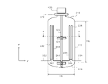
図1は、重合装置100の一例の概略断面図を示す。本実施形態において、重合装置100は、反応容器110と、攪拌機120と、1又は複数の(単に、1以上と称される場合がある。)バッフル130と、1以上の蛇行冷却管140と、1以上の蛇行冷却管150と、ジャケット170と、還流コンデンサ180とを備える。本実施形態において、攪拌機120は、攪拌軸122と、攪拌翼124と、動力機構126とを有する。本実施形態において、バッフル130は、本体132と、1以上のサポート134とを有する。本実施形態において、ジャケット170は、熱媒体の流路172を有する。本実施形態において、還流コンデンサ180は、熱媒体の流路182を有する。
FIG. 1 shows a schematic cross-sectional view of an example of a polymerization device 100. FIG. In this embodiment, the polymerization apparatus 100 includes a reaction vessel 110, a stirrer 120, one or more (sometimes simply referred to as one or more) baffles 130, one or more serpentine cooling pipes 140, It comprises one or more serpentine cooling tubes 150 , a jacket 170 and a reflux condenser 180 . In this embodiment, the stirrer 120 has a stirring shaft 122 , a stirring blade 124 and a power mechanism 126 . In this embodiment, baffle 130 has a body 132 and one or more supports 134 . In this embodiment, the jacket 170 has a heat medium flow path 172 . In this embodiment, the reflux condenser 180 has a heat medium flow path 182 .
本実施形態において、攪拌軸122及び攪拌翼124は、反応容器110の内部に配される。本実施形態において、1以上のバッフル130のそれぞれは、反応容器110の内部に配される。本実施形態において、1以上の蛇行冷却管140のそれぞれは、反応容器110の内部に配される。本実施形態において、1以上の蛇行冷却管150のそれぞれは、反応容器110の内部に配される。
In this embodiment, the stirring shaft 122 and the stirring blades 124 are arranged inside the reaction vessel 110 . In this embodiment, each of the one or more baffles 130 are positioned inside the reaction vessel 110 . In this embodiment, each of the one or more serpentine cooling tubes 140 is disposed inside the reaction vessel 110 . In this embodiment, each of the one or more serpentine cooling tubes 150 is disposed inside the reaction vessel 110 .
本実施形態において、動力機構126は、反応容器110の外部に配される。本実施形態において、ジャケット170は、反応容器110の外部に配される。本実施形態において、還流コンデンサ180は、反応容器110の外部に配される。
In this embodiment, the power mechanism 126 is arranged outside the reaction vessel 110 . In this embodiment, the jacket 170 is arranged outside the reaction vessel 110 . In this embodiment, the reflux condenser 180 is arranged outside the reaction vessel 110 .
本実施形態において、蛇行冷却管140及び蛇行冷却管150は、反応容器110の内面からの距離が異なるように配される。具体的には、蛇行冷却管150は、蛇行冷却管140よりも反応容器110の側面に近い位置に配される。この場合、蛇行冷却管140と、反応容器110の側面との距離L2は、蛇行冷却管150と、反応容器110の側面との距離L1よりも大きい。
In this embodiment, the meandering cooling pipe 140 and the meandering cooling pipe 150 are arranged at different distances from the inner surface of the reaction vessel 110 . Specifically, meandering cooling pipe 150 is arranged at a position closer to the side surface of reaction vessel 110 than meandering cooling pipe 140 . In this case, the distance L2 between the meandering cooling pipe 140 and the side surface of the reaction vessel 110 is greater than the distance L1 between the meandering cooling pipe 150 and the side surface of the reaction vessel 110 .
蛇行冷却管140と、反応容器110の側面との距離L2は、蛇行冷却管140の断面の中心と、反応容器110の側面との距離の最小値であってよい。蛇行冷却管150と、反応容器110の側面との距離L1は、蛇行冷却管150の断面の中心と、反応容器110の側面との距離の最小値であってよい。例えば、蛇行冷却管140又は蛇行冷却管150が円管である場合、蛇行冷却管140又は蛇行冷却管150の断面は円形であり、蛇行冷却管140又は蛇行冷却管150の断面の中心は、当該円の中心である。
The distance L2 between the meandering cooling pipe 140 and the side surface of the reaction vessel 110 may be the minimum distance between the center of the cross section of the meandering cooling pipe 140 and the side surface of the reaction vessel 110. The distance L1 between the meandering cooling pipe 150 and the side surface of the reaction vessel 110 may be the minimum distance between the center of the cross section of the meandering cooling pipe 150 and the side surface of the reaction vessel 110 . For example, if serpentine cooling pipe 140 or serpentine cooling pipe 150 is a circular pipe, the cross section of serpentine cooling pipe 140 or serpentine cooling pipe 150 is circular, and the center of the cross section of serpentine cooling pipe 140 or serpentine cooling pipe 150 is the is the center of the circle.
これにより、本実施形態によれば、反応容器110の内部の熱が効率よく除去され得る。例えば、重合装置100が重合体の製造に用いられる場合、重合装置100は、重合反応において発生する反応熱を効率よく除去することができる。
Thus, according to this embodiment, the heat inside the reaction vessel 110 can be removed efficiently. For example, when the polymerization apparatus 100 is used for polymer production, the polymerization apparatus 100 can efficiently remove reaction heat generated in the polymerization reaction.
ところで、特に、塩化ビニル系の単量体、又は、塩化ビニル系の化合物を主体とする単量体混合物(両者をあわせて、塩化ビニル系単量体と称される場合がある。)の懸濁重合においては、反応容器110の内部に冷却コイル、ドラフトチューブ等の内部構造物が配されると、攪拌機120の所要動力が増加する。また、上記の内部構造物の形状、大きさ及び設置位置は、重合装置100の混合性能に影響を与える。そのため、内部構造物によっては、反応容器110の内部に、流動の緩慢な部分が発生し得る。反応容器110の内部に流動の緩慢な部分が発生すると、反応容器110の内部の温度が不均一になる。その結果、生産される重合体の粒子サイズ及び/又は重合度が不均一になったり、反応容器110の内壁又は内部構造物の表面に重合体のスケールが付着しやすくなったりする。上記のスケールは、重合体を用いた成形製品の品質を損なうフィッシュアイの原因となり得る。
By the way, in particular, the suspension of vinyl chloride monomers or monomer mixtures mainly composed of vinyl chloride compounds (both together are sometimes referred to as vinyl chloride monomers). In the turbid polymerization, if internal structures such as a cooling coil and a draft tube are arranged inside the reaction vessel 110, the required power of the stirrer 120 increases. In addition, the shape, size and installation position of the internal structure described above affect the mixing performance of the polymerization apparatus 100 . Therefore, depending on the internal structure, a portion of slow flow may occur inside the reaction vessel 110 . When a portion of slow flow occurs inside the reaction vessel 110, the temperature inside the reaction vessel 110 becomes non-uniform. As a result, the particle size and/or the degree of polymerization of the produced polymer become non-uniform, and polymer scale tends to adhere to the inner wall of the reaction vessel 110 or the surface of the internal structure. The scale described above can cause fish eyes that impair the quality of molded products using the polymer.
また、除熱効率が同一の条件においては、反応容器110の大型化と、反応時間の短縮とは、トレードオフの関係にある。そのため、反応容器110を大型化しつつ、反応時間を短縮するためには、重合装置100の除熱効率を増大させることが望ましい。
In addition, under the same heat removal efficiency conditions, there is a trade-off relationship between increasing the size of the reaction vessel 110 and shortening the reaction time. Therefore, in order to increase the size of the reaction vessel 110 and shorten the reaction time, it is desirable to increase the heat removal efficiency of the polymerization apparatus 100 .
重合装置100の除熱効率を増大させる方法としては、冷媒の温度を低下させることが考えられる。しかしながら、冷媒の温度を低下させると、重合体の製造コストが増加する。重合装置100の除熱効率を増大させる他の方法としては、ジャケット170又は還流コンデンサ180による除熱量を増加させることが考えられる。特に、40m3以上の大型重合器となると、ジャケット170による除熱だけでは除熱量が不足するので、還流コンデンサ180による除熱量を大きく増加させることが考えられる。しかしながら、還流コンデンサ180の除熱負荷を増加させると、反応容器110の内部における重合体スラリーの発泡量が増加し得る。重合体スラリーの発泡量が増加すると、還流コンデンサ180の除熱能力が低下したり、還流コンデンサ180の内部に重合体のスケールが付着したりする場合がある。
A conceivable method for increasing the heat removal efficiency of the polymerization apparatus 100 is to lower the temperature of the refrigerant. However, lowering the temperature of the coolant increases the production cost of the polymer. Another method for increasing the heat removal efficiency of the polymerization apparatus 100 is to increase the amount of heat removed by the jacket 170 or the reflux condenser 180 . In particular, in the case of a large-sized polymerization vessel of 40 m 3 or more, the amount of heat removed by the jacket 170 alone is insufficient. However, increasing the heat removal load of the reflux condenser 180 can increase the foaming amount of the polymer slurry inside the reaction vessel 110 . When the foaming amount of the polymer slurry increases, the heat removal capability of the reflux condenser 180 may decrease, or polymer scale may adhere to the inside of the reflux condenser 180 .
また、例えば、特許文献1に記載された重合装置を用いて重合器の容量を大型化する場合、蛇行配管の伝熱面積が不足すると、製品の品質を維持しつつ反応時間を短縮することが困難となる可能性がある。一方、特許文献2に記載された重合装置においては、比較的簡単な構造物により、伝熱面積を増加させることができる。しかしながら、装置の構造上、バッフルと、コイル状冷却管とを略同一円周上に配置することができない。そのため、装置の容量に対するコイル状冷却管を設置可能な領域の割合が比較的小さい。特許文献2に記載された重合装置を用いて重合器の容量を大型化する場合、伝熱面積を増加させるためにコイル状冷却管同士の距離を小さくすると、重合装置の混合性能が低下する可能性がある。加えて、外乱などによりコイル状冷却管の表面にスケール又は塊状の反応物が生じた場合、缶内作業が煩雑となるので、上記のスケールなどを十分に除去することが難しい。
Further, for example, when the capacity of the polymerization vessel is increased using the polymerization apparatus described in Patent Document 1, if the heat transfer area of the meandering pipe is insufficient, the reaction time can be shortened while maintaining the quality of the product. can be difficult. On the other hand, in the polymerization apparatus described in Patent Document 2, the heat transfer area can be increased with a relatively simple structure. However, due to the structure of the device, the baffle and the coiled cooling pipe cannot be arranged on substantially the same circumference. Therefore, the ratio of the area where the coiled cooling pipe can be installed is relatively small with respect to the capacity of the device. When increasing the capacity of the polymerization apparatus using the polymerization apparatus described in Patent Document 2, if the distance between the coiled cooling pipes is reduced in order to increase the heat transfer area, the mixing performance of the polymerization apparatus may decrease. have a nature. In addition, when scale or agglomerated reactants are generated on the surface of the coiled cooling pipe due to disturbance or the like, work inside the can becomes complicated, and it is difficult to sufficiently remove the scale or the like.
これに対して、本実施形態に係る重合装置100によれば、反応容器110の内面からの距離が異なるように、蛇行冷却管140及び蛇行冷却管150が配される。これにより、重合装置100の混合性能に対する影響の小さな比較的簡単な構造物を用いて、伝熱面積を増加させることができる。また、本実施形態に係る重合装置100によれば、蛇行冷却管140及び蛇行冷却管150の設置位置に関する自由度が大きい。例えば、1以上の蛇行冷却管140及び1以上の蛇行冷却管150の少なくも1つと、バッフル130とが、略同一円周上に配置され得る。これにより、蛇行冷却管150が重合装置100の混合性能に与える影響をより小さくしつつ、装置全体の伝熱面積を増加させることができる。
On the other hand, according to the polymerization apparatus 100 according to the present embodiment, the meandering cooling pipes 140 and 150 are arranged at different distances from the inner surface of the reaction vessel 110 . As a result, the heat transfer area can be increased using a relatively simple structure that has little effect on the mixing performance of the polymerization apparatus 100 . Moreover, according to the polymerization apparatus 100 according to the present embodiment, there is a large degree of freedom regarding the installation positions of the meandering cooling pipes 140 and 150 . For example, at least one of the one or more serpentine cooling tubes 140 and one or more of the one or more serpentine cooling tubes 150 and the baffle 130 may be arranged on substantially the same circumference. As a result, the heat transfer area of the entire apparatus can be increased while reducing the influence of the meandering cooling pipe 150 on the mixing performance of the polymerization apparatus 100 .
(重合装置100の各部の概要)
本実施形態において、反応容器110は、合成反応の原料を貯留する。重合装置100が重合体の製造に用いられる場合、例えば、反応容器110の内部に、重合性の単量体、重合開始剤、水性媒体、分散助剤等が仕込まれた後、重合が開始される。分散助剤としては、例えば、任意の界面活性剤が使用され得る。
(Overview of Each Part of Polymerization Apparatus 100)
In this embodiment, the reaction vessel 110 stores raw materials for the synthesis reaction. When the polymerization apparatus 100 is used to produce a polymer, for example, the reaction vessel 110 is charged with a polymerizable monomer, a polymerization initiator, an aqueous medium, a dispersion aid, and the like, and then polymerization is started. be. As a dispersing aid, for example, any surfactant can be used.
反応容器110は、例えば、筒状の形状を有する。反応容器110は、円筒状の形状を有してもよく、角筒状の形状を有してもよい。反応容器110は、例えば、反応容器110の延伸方向(図中、z方向である。)が鉛直方向となるように設置される。
The reaction container 110 has, for example, a cylindrical shape. The reaction vessel 110 may have a cylindrical shape or a rectangular tubular shape. The reaction container 110 is installed, for example, so that the extending direction of the reaction container 110 (the z-direction in the drawing) is the vertical direction.
反応容器110を、反応容器110の延伸方向に垂直な面(図中、xy平面である。)で切断した断面(横断面と称される場合がある。)の形状としては、円形、楕円形、多角形などが例示される。なお、反応容器110の横断面の形状は、実質的に、円形、楕円形、多角形とみなすことのできる形状であってもよい。
The shape of a cross section (sometimes referred to as a cross section) obtained by cutting the reaction vessel 110 along a plane perpendicular to the extending direction of the reaction vessel 110 (the xy plane in the drawing) may be circular or elliptical. , polygons, and the like. The shape of the cross section of the reaction vessel 110 may be substantially circular, elliptical, or polygonal.
反応容器110の内容量は特に限定されるものではないが、反応容器110の内容量は、例えば、1~300m3である。反応容器110の内容量の下限値は、40m3であってもよく、80m3であってもよく、100m3であってもよく、120m3であってもよく、130m3であってもよく、150m3であってもよく、200m3であってもよく、250m3であってもよい。反応容器110の内容量の上限値は、300m3以上であってもよい。反応容器110の内容量の上限値は、350m3であってもよく、400m3であってもよい。反応容器110の内容量が大きいほど、本実施形態による冷却能力の向上が有利に作用し得る。
Although the content of the reaction vessel 110 is not particularly limited, the content of the reaction vessel 110 is, for example, 1 to 300 m 3 . The lower limit of the content of the reaction vessel 110 may be 40 m3 , 80 m3 , 100 m3 , 120 m3 , or 130 m3 . , may be 150 m3 , may be 200 m3 , or may be 250 m3 . The upper limit of the content of the reaction vessel 110 may be 300 m 3 or more. The upper limit of the content of the reaction vessel 110 may be 350 m 3 or 400 m 3 . The greater the internal capacity of the reaction vessel 110, the more advantageous the improvement in the cooling capacity according to the present embodiment.
反応容器110の内容量は、反応容器110が、反応容器110の予め定められた上限位置まで液体を貯留した場合における容量として定められる。反応容器110の内容量は、例えば、反応容器110の内部に撹拌軸、翼、バッフル、コイル等の内部構造物が配されていない場合における、反応容器110の内部の体積である。
The internal capacity of the reaction container 110 is determined as the capacity when the liquid is stored in the reaction container 110 up to a predetermined upper limit position of the reaction container 110 . The internal volume of the reaction vessel 110 is, for example, the internal volume of the reaction vessel 110 when internal structures such as a stirring shaft, blades, baffles, and coils are not disposed inside the reaction vessel 110 .
上述されたとおり、反応容器110の大型化と、反応時間の短縮とは、トレードオフの関係にある。反応容器110の内容量が40m3以上になると、重合装置100の除熱効率が不足しやすくなり、反応容器110を大型化しつつ、反応時間を短縮することが難しい。特に、反応容器110の内容量が80m3以上の場合、本実施形態に係る重合装置100の効果がより顕著に表れる。反応容器110の詳細は後述される。
As described above, there is a trade-off relationship between increasing the size of the reaction vessel 110 and shortening the reaction time. When the internal volume of the reaction vessel 110 is 40 m 3 or more, the heat removal efficiency of the polymerization apparatus 100 tends to be insufficient, and it is difficult to shorten the reaction time while increasing the size of the reaction vessel 110 . In particular, when the content of the reaction vessel 110 is 80 m 3 or more, the effects of the polymerization apparatus 100 according to this embodiment are more pronounced. Details of the reaction vessel 110 will be described later.
本実施形態において、攪拌機120は、反応容器110の内部に貯留された液体を攪拌する。本実施形態において、攪拌軸122は、攪拌翼124を保持し、攪拌翼124を回転させる。本実施形態において、攪拌翼124は、攪拌軸122に取り付けられ、反応容器110の内部に貯留された液体を攪拌する。
In this embodiment, the stirrer 120 stirs the liquid stored inside the reaction vessel 110 . In this embodiment, the stirring shaft 122 holds the stirring blades 124 and rotates the stirring blades 124 . In this embodiment, the stirring blade 124 is attached to the stirring shaft 122 and stirs the liquid stored inside the reaction vessel 110 .
攪拌翼124の形状は特に限定されるものではないが、攪拌翼124の形状としては、ファウドラー翼、ブルーマージン翼、パドル翼、傾斜パドル翼、タービン翼、プロペラ翼、及び、これらの組み合わせが例示される。これにより、攪拌軸122が回転することにより、攪拌軸122から放射状に外周へ向う吐出流が発生する。攪拌翼124が有する翼の枚数は特に限定されるものではないが、上記の翼の枚数としては、2~6枚が例示される。攪拌翼124の設置位置及び設置数量は特に限定されるものではないが、攪拌翼124は、多段に設置されることが好ましい。攪拌翼124の段数としては、2~6段が例示される。
The shape of the stirring blades 124 is not particularly limited, but examples of the shape of the stirring blades 124 include Faudler blades, Bluemargin blades, paddle blades, inclined paddle blades, turbine blades, propeller blades, and combinations thereof. be done. As a result, the stirring shaft 122 rotates to generate a discharge flow radially from the stirring shaft 122 toward the outer periphery. The number of blades included in the stirring blade 124 is not particularly limited, but the number of blades is exemplified from 2 to 6. The installation position and installation number of the stirring blades 124 are not particularly limited, but the stirring blades 124 are preferably installed in multiple stages. As the number of stages of the stirring blades 124, 2 to 6 stages are exemplified.
本実施形態において、動力機構126は、攪拌軸122を回転させる。動力機構126は、例えば、動力を発生させる動力部(図示されていない。)と、動力部が発生させた動力を攪拌軸122に伝達する動力伝達部(図示されていない。)動力部としては、電動機が例示される。動力伝達部としては、減速機が例示される。
In this embodiment, the power mechanism 126 rotates the stirring shaft 122 . The power mechanism 126 includes, for example, a power section (not shown) that generates power and a power transmission section (not shown) that transmits the power generated by the power section to the stirring shaft 122. , electric motors are exemplified. A speed reducer is exemplified as the power transmission unit.
攪拌軸122の回転数、並びに、攪拌翼124の形状、大きさ、翼の枚数、設置位置、設置数量及び設置間隔Piは、重合装置100の用途に応じて、適宜決定される。攪拌軸122の回転数、並びに、攪拌翼124の形状、大きさ、翼の枚数、設置位置、設置数量及び設置間隔Piは、例えば、反応容器110の内容量、反応容器110の形状、反応容器110の内部に配された内部構造物、除熱手段の構成、除熱能力、及び、重合のために仕込まれる原材料の組成を考慮して決定される。
The number of rotations of the stirring shaft 122, the shape, size, number of blades, installation position, number of installations, and installation interval Pi of the stirring blades 124 are appropriately determined according to the application of the polymerization apparatus 100. The number of rotations of the stirring shaft 122, the shape, size, number of blades, installation position, number of installations, and installation interval Pi of the stirring blades 124 are, for example, determined by the content of the reaction vessel 110, the shape of the reaction vessel 110, and the reaction vessel. It is determined in consideration of the internal structure arranged inside 110, the configuration of the heat removal means, the heat removal capacity, and the composition of the raw material charged for polymerization.
例えば、重合装置100が懸濁重合の用途に用いられる場合、内容物(この場合、水性懸濁混合物である。)に加えられる撹拌エネルギーが、80~200kgf・m/s・m3となるように、攪拌軸122の回転数が決定される。ここで、内容物に加えられる「撹拌エネルギー」は、重合装置100の運転中に、動力機構126に配された撹拌機用駆動モーターに負荷されるエネルギーAから、モーター効率及び伝導ロス、メカニカルロス等の各種のエネルギーロスBを差し引いた、内容物の単位量(単位内容量と称される場合がある。)当りの撹拌に要する正味のエネルギーとして定められる。上記の単位量としては、単位質量、単位体積などが例示される。例えば、内容物の体積をCとすると、撹拌エネルギーは下記の数式(1)により算出される。
(数式1)
(A-B)/C [kgf・m/s・m3]
For example, when the polymerization apparatus 100 is used for suspension polymerization, the stirring energy applied to the contents (in this case, the aqueous suspension mixture) is 80 to 200 kgf·m/s·m 3 . First, the rotation speed of the stirring shaft 122 is determined. Here, the "stirring energy" applied to the contents is calculated from the energy A applied to the stirrer driving motor arranged in the power mechanism 126 during the operation of the polymerization apparatus 100, the motor efficiency, the conduction loss, and the mechanical loss. It is defined as the net energy required for stirring per unit amount of contents (sometimes referred to as unit content) after subtracting various energy losses B such as. Examples of the above-mentioned unit amount include unit mass and unit volume. For example, if the volume of the contents is C, the stirring energy is calculated by the following formula (1).
(Formula 1)
(AB)/C [kgf·m/s·m 3 ]
撹拌機用駆動モーターに負荷されるエネルギーは、例えば、ワットメーターなどの計測機器を用いて電気的に計測することとができる。また、撹拌エネルギーは、攪拌軸122の回転数を変更することにより容易に調節することができる。
The energy loaded on the agitator drive motor can be measured electrically using a measuring device such as a watt meter. Also, the stirring energy can be easily adjusted by changing the rotation speed of the stirring shaft 122 .
重合装置100における攪拌軸122の回転数は、例えば、事前に実施されたパイロットプラントにおける重合試験に基づいて決定される。一般的に、パイロットプラントから重合装置100へのスケールアップは、重合装置100の攪拌状態と、パイロットプラントの攪拌状態とが略一致するように実施される。例えば、パイロットプラント及び重合装置100において、反応容器110の形状及び大きさと、攪拌翼124、バッフル130、蛇行冷却管140、蛇行冷却管150などの内部構造物の形状及び大きさ並びに配置とが相似するように、各内部構造物の形状及び大きさ並び配置が決定される。
The number of revolutions of the stirring shaft 122 in the polymerization device 100 is determined, for example, based on a polymerization test conducted in advance in a pilot plant. In general, the scale-up from the pilot plant to the polymerization apparatus 100 is carried out so that the agitation state of the polymerization apparatus 100 and the agitation state of the pilot plant are substantially the same. For example, in the pilot plant and the polymerization apparatus 100, the shape and size of the reaction vessel 110 and the shape, size and arrangement of internal structures such as the stirring blade 124, the baffle 130, the serpentine cooling pipe 140 and the serpentine cooling pipe 150 are similar. The shape, size and arrangement of each internal structure are determined so as to do so.
そこで、一実施形態によれば、重合装置100における撹拌エネルギーと、パイロットプラントにおける撹拌エネルギーとが略同一となるように、重合装置100における攪拌軸122の回転数が決定され得る。上述されたとおり、撹拌エネルギーは、例えば「(A-B)/C」として算出される。攪拌エネルギーに基づいて攪拌軸122の回転数を決定する手法としては、任意の公知の手法が採用され得る。
Therefore, according to one embodiment, the rotation speed of the stirring shaft 122 in the polymerization device 100 can be determined so that the stirring energy in the polymerization device 100 and the stirring energy in the pilot plant are substantially the same. As described above, the stirring energy is calculated as "(AB)/C", for example. Any known method can be adopted as a method for determining the rotation speed of the stirring shaft 122 based on the stirring energy.
パイロットプラントにおける攪拌軸122の回転数は、例えば、下記の手順により決定される。例えば、パイロットプラントを用いた重合試験により、パイロットプラントにおける攪拌軸122の回転数と、重合体の品質との関係が得られる。これにより、目的とする品質の重合体が得られるような攪拌軸122の回転数が決定される。上記の品質は、特に限定されるものではないが、上記の品質としては、例えば、粒子サイズが例示される。
The rotation speed of the stirring shaft 122 in the pilot plant is determined, for example, by the following procedure. For example, a polymerization test using a pilot plant provides the relationship between the number of rotations of the stirring shaft 122 in the pilot plant and the quality of the polymer. Thereby, the number of revolutions of the stirring shaft 122 is determined so that a polymer of the desired quality can be obtained. Although the quality is not particularly limited, an example of the quality is particle size.
具体的には、パイロットプラントを用いた重合試験において、目的とする重合体の還元粘度(K値と称される場合がある。)に応じて、重合温度が設定される。ここで、重合温度と、重合体の平均重合度とは相関関係を有しており、重合体のK値は、重合体の平均重合度を表す指標として広く用いられている。
Specifically, in a polymerization test using a pilot plant, the polymerization temperature is set according to the reduced viscosity (sometimes referred to as the K value) of the target polymer. Here, the polymerization temperature and the average degree of polymerization of the polymer have a correlation, and the K value of the polymer is widely used as an index representing the average degree of polymerization of the polymer.
また、パイロットプラントを用いた重合試験において、パイロットプラントの除熱能力に応じて、重合時間が決定される。例えば、(i)出発原料となる単量体の仕込量、(ii)重合開始剤の投入量、及び、(iii)パイロットプラントの除熱能力に応じて、反応による発熱量がパイロットプラントの除熱能力を超えないように、重合時間が決定される。
Also, in polymerization tests using a pilot plant, the polymerization time is determined according to the heat removal capacity of the pilot plant. For example, depending on (i) the charged amount of the monomer as the starting material, (ii) the charged amount of the polymerization initiator, and (iii) the heat removal capacity of the pilot plant, the amount of heat generated by the reaction can be removed by the pilot plant. The polymerization time is determined so that the thermal capacity is not exceeded.
このように、パイロットプラントが十分な除熱能力を有するように重合時間が設定された場合、K値の目標値に応じて重合温度を設定することで、目的とする平均重合度を有する重合体が生成され得る。そこで、例えば、重合温度及び重合時間が同一で、攪拌軸122の回転数が異なる複数の条件のそれぞれについて重合試験が実施される。
In this way, when the polymerization time is set so that the pilot plant has sufficient heat removal capacity, by setting the polymerization temperature according to the target value of the K value, a polymer having a desired average degree of polymerization can be generated. Therefore, for example, a polymerization test is performed under each of a plurality of conditions in which the polymerization temperature and polymerization time are the same, and the rotation speed of the stirring shaft 122 is different.
攪拌軸122の回転数が異なる複数の試験結果に基づいて、パイロットプラントにおける攪拌軸122の回転数と、重合体の品質との関係が得られる。これにより、重合体の品質の目標値が決定されれば、目的とする品質の重合体が得られるような攪拌軸122の回転数が決定され得る。
Based on the results of multiple tests with different rotation speeds of the stirring shaft 122, the relationship between the rotation speed of the stirring shaft 122 in the pilot plant and the quality of the polymer can be obtained. Thus, once the target value of the quality of the polymer is determined, the rotational speed of the stirring shaft 122 can be determined so as to obtain the polymer of the desired quality.
パイロットプラントが十分な除熱能力を有するように重合時間が設定された場合、K値の目標値に応じて重合温度を設定することで、目的とする平均重合度を有する重合体が生成され得る。一方、設定された重合時間に対してパイロットプラントの除熱能力が不十分である場合、重合反応による発熱により重合温度が上昇する。上述されたとおり、重合温度と、生成された重合体の平均重合度との間には相関関係が存在する。そのため、重合温度が上昇すると、生成された重合体のK値と、K値の目標値との誤差が大きくなる。また、重合温度の上昇具合によっては、反応の制御が不可能となり得る。
When the polymerization time is set so that the pilot plant has sufficient heat removal capacity, a polymer having a desired average degree of polymerization can be produced by setting the polymerization temperature according to the target value of the K value. . On the other hand, if the heat removal capability of the pilot plant is insufficient for the set polymerization time, the heat generated by the polymerization reaction will raise the polymerization temperature. As mentioned above, there is a correlation between the polymerization temperature and the average degree of polymerization of the polymer produced. Therefore, when the polymerization temperature rises, the error between the K value of the produced polymer and the target value of the K value increases. In addition, depending on how the polymerization temperature rises, it may become impossible to control the reaction.
このように、生成された重合体のK値は、重合装置100の除熱能力に関する指標として採用され得る。例えば、重合装置100を用いて重合体を生成した場合において、設定された重合時間に対して目的としたK値が得られたとき、重合装置100は十分な除熱能力を有すると判定され得る。
Thus, the K value of the produced polymer can be used as an index for the heat removal capacity of the polymerization apparatus 100. For example, when a polymer is produced using the polymerization apparatus 100 and a desired K value is obtained for a set polymerization time, it can be determined that the polymerization apparatus 100 has sufficient heat removal capability. .
上述されたとおり、パイロットプラントから重合装置100へのスケールアップは、重合装置100の攪拌状態と、パイロットプラントの攪拌状態とが略一致するように実施され得る。例えば、目的とする重合装置100における反応容器110の内径及び/又は直胴部高さに対する、反応容器110の内部に配される各内部構造物の大きさの比率と、パイロットプラントの反応容器の内径及び/又は直胴部高さに対する、パイロットプラントにおける各内部構造物の大きさの比率とが略一致する場合において、重合装置100における攪拌エネルギーと、パイロットプラントにおける攪拌エネルギーとが略同一であるとき、スケールアップされた重合装置100の攪拌状態と、パイロットプラントの攪拌状態とが略一致する。
As described above, the scale-up from the pilot plant to the polymerization apparatus 100 can be carried out so that the agitation state of the polymerization apparatus 100 and the agitation state of the pilot plant are substantially the same. For example, the ratio of the size of each internal structure arranged inside the reaction vessel 110 to the inner diameter and/or the height of the straight body of the reaction vessel 110 in the target polymerization apparatus 100, and the size of the reaction vessel of the pilot plant When the ratio of the size of each internal structure in the pilot plant to the inner diameter and/or the height of the straight body portion is substantially the same, the stirring energy in the polymerization apparatus 100 and the stirring energy in the pilot plant are substantially the same. At this time, the agitation state of the scaled-up polymerization apparatus 100 and the agitation state of the pilot plant substantially match.
例えば、パイロットプラントと、目的とする重合装置100との間で、反応容器110の直胴部の高さに対する、バッフル130の延伸方向(図中、上下方向である。)の長さの比が略同一となるように、目的とする重合装置100におけるバッフル130の大きさが決定される。パイロットプラントと、目的とする重合装置100との間で、反応容器110の内部の直径(内径と称される場合がある。)に対する、バッフル130の延伸方向に略垂直な方向(図中、左右方向である)の長さの比が略同一となるように、目的とする重合装置100におけるバッフル130の大きさが決定される。パイロットプラントと、目的とする重合装置100との間で、バッフル130の個数及び配置が略同一となるように、目的とする重合装置100におけるバッフル130の個数及び配置が決定される。他の構造物(例えば、攪拌翼124、蛇行冷却管140、蛇行冷却管150などである。)についても同様である。
For example, between the pilot plant and the target polymerization apparatus 100, the ratio of the length of the baffle 130 in the extension direction (vertical direction in the figure) to the height of the straight body portion of the reaction vessel 110 is The size of the baffle 130 in the target polymerization apparatus 100 is determined so as to be substantially the same. Between the pilot plant and the target polymerization apparatus 100, the direction (left and right in the figure) substantially perpendicular to the extension direction of the baffle 130 with respect to the inner diameter (sometimes referred to as the inner diameter) of the reaction vessel 110 The size of the baffle 130 in the target polymerization apparatus 100 is determined so that the ratio of the lengths of the two directions is substantially the same. The number and arrangement of the baffles 130 in the intended polymerization apparatus 100 are determined so that the number and arrangement of the baffles 130 are substantially the same between the pilot plant and the intended polymerization apparatus 100 . The same applies to other structures (for example, stirring blades 124, meandering cooling pipes 140, meandering cooling pipes 150, etc.).
また、上述されたとおり、スケールアップされた重合装置100における重合体の品質の目標値が決定されれば、上述されたパイロットプラントにおける攪拌軸122の回転数と、重合体の品質との関係に基づいて、スケールアップされた重合装置100における攪拌軸122の回転数が決定され得る。具体的には、まず、(i)重合装置100における重合体の品質の目標値、及び、(ii)パイロットプラントにおける攪拌軸122の回転数と、重合体の品質との関係に基づいて、パイロットプラントにおける攪拌軸122の回転数が決定される。次に、重合装置100における攪拌エネルギーと、パイロットプラントにおける攪拌エネルギーとが略同一となるように、重合装置100における攪拌軸122の回転数が決定される。
Further, as described above, once the target value for the quality of the polymer in the scaled-up polymerization apparatus 100 is determined, the relationship between the rotation speed of the stirring shaft 122 in the pilot plant and the quality of the polymer is Based on this, the rotation speed of the stirring shaft 122 in the scaled-up polymerization apparatus 100 can be determined. Specifically, first, based on (i) the target value of the quality of the polymer in the polymerization apparatus 100, and (ii) the relationship between the rotation speed of the stirring shaft 122 in the pilot plant and the quality of the polymer, the pilot The number of revolutions of the stirring shaft 122 in the plant is determined. Next, the rotational speed of the stirring shaft 122 in the polymerization apparatus 100 is determined so that the stirring energy in the polymerization apparatus 100 and the stirring energy in the pilot plant are substantially the same.
これにより、目的とする重合装置100の(i)攪拌翼124の形状、大きさ、翼の枚数、設置位置、設置数量及び設置間隔Pi、並びに、(ii)反応容器110の内容量、反応容器110の形状及び反応容器110の内部に配された内部構造物などを考慮して、上記の単位内容量当たりの撹拌エネルギー[kgf・m/s・m3]を厳密に計測することなく、目的とする重合装置100の攪拌軸122の回転数が決定され得る。なお、目的とする重合装置100における攪拌軸122の回転数は、重合試験のシミュレーション結果に基づいて決定されてもよい。
As a result, (i) the shape, size, number of blades, installation position, installation number, and installation interval Pi of the stirring blades 124 of the target polymerization apparatus 100, and (ii) the content of the reaction vessel 110, the reaction vessel Considering the shape of 110 and the internal structure arranged inside the reaction vessel 110 , the purpose The number of rotations of the stirring shaft 122 of the polymerization apparatus 100 can be determined as follows. The number of revolutions of the stirring shaft 122 in the intended polymerization apparatus 100 may be determined based on the simulation results of the polymerization test.
本実施形態において、バッフル130は、重合装置100の混合性能を向上させる。例えば、バッフル130は、反応容器110の内部における上下方向の混合性能を向上させる。バッフル130の設置位置は特に限定されるものではないが、例えば、バッフル130は、反応容器110の内壁の近傍に配される。バッフル130は、反応容器110の側壁により支持されてよい。他の実施形態において、バッフル130は、反応容器110の天板又は底板により支持され、攪拌翼124の近傍に配される。バッフル130は、重合装置100が重合体の製造に用いられる場合に、バッフル130の上端が液相に没するように配されてもよく、バッフル130の上端が液相に没しないように配されてもよい。
In this embodiment, the baffle 130 improves the mixing performance of the polymerization device 100. For example, the baffle 130 improves vertical mixing within the reaction vessel 110 . Although the installation position of the baffle 130 is not particularly limited, the baffle 130 is arranged near the inner wall of the reaction vessel 110, for example. Baffles 130 may be supported by sidewalls of reaction vessel 110 . In another embodiment, the baffle 130 is supported by the top or bottom plate of the reaction vessel 110 and placed near the stirring blades 124 . The baffle 130 may be arranged so that the upper end of the baffle 130 is submerged in the liquid phase when the polymerization apparatus 100 is used for polymer production, and is arranged so that the upper end of the baffle 130 is not submerged in the liquid phase. may
バッフル130の個数は、1~12本程度であることが好ましく、2~8本程度であることが好ましく、3~6本程度であることがより好ましく、4~6本程度であることがさらに好ましい。偶数個のバッフル130が、反応容器110の延伸軸(中心軸と称される場合がある。)の周りに略対称的に配置されることが好ましい。これにより、重合装置100の混合性能がさらに向上し、液体の滞留が抑制される。その結果、スケールの発生が抑制され得る。
The number of baffles 130 is preferably about 1 to 12, preferably about 2 to 8, more preferably about 3 to 6, and more preferably about 4 to 6. preferable. An even number of baffles 130 are preferably arranged substantially symmetrically around the elongated axis (sometimes referred to as the central axis) of reaction vessel 110 . As a result, the mixing performance of the polymerization apparatus 100 is further improved, and liquid retention is suppressed. As a result, scale generation can be suppressed.
本実施形態において、バッフル130の本体132は、重合装置100の混合性能を向上させる。本体132の形状は特に限定されるものではないが、本体132は、例えば、反応容器110の延伸方向に略平行に延伸する板状又は筒状の形状を有する。本体132が円筒状の形状を有する場合、本体132の直径は、40~500mmであってよい。本体132の延伸方向(図中、z方向である。)の長さBh(高さBhと称される場合がある。)は、特に限定されない。
In this embodiment, the body 132 of the baffle 130 improves the mixing performance of the polymerization apparatus 100. Although the shape of the main body 132 is not particularly limited, the main body 132 has, for example, a plate-like or tubular shape extending substantially parallel to the extending direction of the reaction vessel 110 . If the body 132 has a cylindrical shape, the diameter of the body 132 may be 40-500 mm. The length Bh (sometimes referred to as height Bh) of the extension direction (the z-direction in the drawing) of the main body 132 is not particularly limited.
本体132の延伸方向に略垂直な方向(図中、x又はy方向である。)の長さBw(幅Bwと称される場合がある。)は、特に限定されない。反応容器110の内径に対する、本体132の幅Bwの割合は、1~10%であってよく、2.5~7.5%であってよく、3~7%であってよい。
The length Bw (sometimes referred to as width Bw) of the direction substantially perpendicular to the extending direction of the main body 132 (the x or y direction in the drawing) is not particularly limited. The ratio of the width Bw of the main body 132 to the inner diameter of the reaction vessel 110 may be 1-10%, 2.5-7.5%, or 3-7%.
本体132が筒状の形状を有する場合、反応容器110の直胴部の横断面の面積に対する、それぞれが筒状の形状を有する1以上の本体132の横断面の面積の合計値の割合は、0.4~3%であってよい。上記の割合が0.4%未満である場合、邪魔板としての機能が不足し、反応容器110の内部における上下方向の混合が不十分になる可能性がある。例えば、重合装置100が単一のバッフル130を備える場合、上記の割合が0.4%未満になり得る。例えば、塩化ビニル系単量体の懸濁重合において、反応容器110の内部における上下方向の混合が不十分となった場合、生産された重合体の粒度分布がブロードとなり得る。その結果、生産された重合体をシート状に成形した場合に、例えば、フィッシュアイが増加して、成形製品の品質が低下する可能性がある。
When the main body 132 has a cylindrical shape, the ratio of the total cross-sectional area of one or more main bodies 132 each having a cylindrical shape to the cross-sectional area of the straight body portion of the reaction vessel 110 is It may be 0.4-3%. If the above ratio is less than 0.4%, the function as a baffle may be insufficient, resulting in insufficient mixing in the vertical direction inside the reaction vessel 110 . For example, if the polymerization apparatus 100 includes a single baffle 130, the above percentage can be less than 0.4%. For example, in the suspension polymerization of vinyl chloride-based monomers, if the vertical mixing inside the reaction vessel 110 is insufficient, the produced polymer may have a broad particle size distribution. As a result, when the produced polymer is molded into a sheet, for example, fish eyes may increase and the quality of the molded product may deteriorate.
一方、上記の割合が3%を超えた場合、攪拌機120の所要動力が過度に増加する。また、バッフル130と、反応容器110の内壁面との間における液体の流動性が低下し得る。その結果、反応容器110又は反応容器110の内部の構造物にスケールが付着しやすくなる可能性がある。例えば、重合装置100が8本を超えるバッフル130を備える場合、重合装置100の設計によっては上記の割合が3%を超え得る。
On the other hand, if the above ratio exceeds 3%, the required power of the stirrer 120 increases excessively. Also, fluidity between the baffle 130 and the inner wall surface of the reaction vessel 110 may be reduced. As a result, scale may easily adhere to the reaction vessel 110 or structures inside the reaction vessel 110 . For example, if the polymerization apparatus 100 includes more than eight baffles 130, the percentage may exceed 3% depending on the design of the polymerization apparatus 100.
少なくとも1つのバッフル130の本体132は、熱媒体を流通させるための流路を有してよい。上記の流路は、本体132の内部に形成されてもよく、本体132の外部に配されてもよい。上記の流路は、一重管であってもよく、二重管構造を有してもよい。
The main body 132 of at least one baffle 130 may have a channel for circulating the heat medium. The flow path described above may be formed inside the main body 132 or may be arranged outside the main body 132 . The above flow path may be a single tube or may have a double tube structure.
熱媒体は、公知の冷媒であってよい。冷媒としては、水、ブライン、フレオン、その他の液化ガスなどが例示される。冷媒として液化ガスが用いられる場合、当該液化ガスは、蛇行冷却管140の内部で蒸発することで、冷媒として機能してよい。冷媒の線速は、0.1~6.0m/s程度であってよい。
The heat medium may be a known refrigerant. Examples of refrigerants include water, brine, freon, and other liquefied gases. If a liquefied gas is used as the coolant, the liquefied gas may function as a coolant by evaporating inside the serpentine cooling tube 140 . The linear velocity of the refrigerant may be about 0.1 to 6.0 m/s.
本体132は、例えば、サポート134を介して、反応容器110の内壁面に接続される。本体132と、重合装置100の内壁面との距離は、40mm以上であることが好ましい。上記の距離が40mm未満の場合、反応容器110の内部の気液界面付近において、反応容器110の内壁面と、バッフル130との間に重合体のスケールが付着しやすくなる場合がある。本体132の詳細は後述される。
The main body 132 is connected to the inner wall surface of the reaction container 110 via a support 134, for example. The distance between the main body 132 and the inner wall surface of the polymerization apparatus 100 is preferably 40 mm or more. If the distance is less than 40 mm, polymer scale may easily adhere between the inner wall surface of the reaction vessel 110 and the baffle 130 near the gas-liquid interface inside the reaction vessel 110 . Details of the main body 132 will be described later.
本実施形態において、サポート134は、本体132を保持する。例えば、サポート134の一端は、反応容器110の内壁面に接し、サポート134の他端は、本体132に接する。上述されたとおり、サポート134は、本体132と、重合装置100の内壁面との距離が40mm以上となるように、本体132を保持してよい。
In this embodiment, the support 134 holds the body 132 . For example, one end of the support 134 contacts the inner wall surface of the reaction vessel 110 and the other end of the support 134 contacts the main body 132 . As described above, the support 134 may hold the main body 132 such that the distance between the main body 132 and the inner wall surface of the polymerization apparatus 100 is 40 mm or more.
本実施形態において、蛇行冷却管140は、その内部に熱媒体を流通させるための流路が形成される。蛇行冷却管140は、一重管であってよい。蛇行冷却管140は、蛇行冷却管150よりも、反応容器110の中心軸に近い位置に配される。蛇行冷却管140の個数は、1~12本程度であることが好ましく、2~8本程度であることが好ましく、3~6本程度であることがより好ましく、4~6本程度であることがさらに好ましい。偶数個の蛇行冷却管140が、反応容器110の中心軸の周りに略対称的に配置されることが好ましい。
In this embodiment, the meandering cooling pipe 140 is formed with a channel for circulating the heat medium therein. Serpentine cooling tube 140 may be a single tube. The meandering cooling pipe 140 is arranged closer to the central axis of the reaction vessel 110 than the meandering cooling pipe 150 is. The number of meandering cooling pipes 140 is preferably about 1 to 12, preferably about 2 to 8, more preferably about 3 to 6, and more preferably about 4 to 6. is more preferred. An even number of serpentine cooling pipes 140 are preferably arranged substantially symmetrically around the central axis of reaction vessel 110 .
熱媒体は、公知の冷媒であってよい。冷媒としては、水、ブライン、フレオン、その他の液化ガスなどが例示される。冷媒として液化ガスが用いられる場合、当該液化ガスは、蛇行冷却管140の内部で蒸発することで、冷媒として機能してよい。冷媒の線速は、0.1~6.0m/s程度であってよい。
The heat medium may be a known refrigerant. Examples of refrigerants include water, brine, freon, and other liquefied gases. If a liquefied gas is used as the coolant, the liquefied gas may function as a coolant by evaporating inside the serpentine cooling tube 140 . The linear velocity of the refrigerant may be about 0.1 to 6.0 m/s.
本実施形態において、蛇行冷却管140の少なくとも一部は、繰り返し屈曲しながら延伸する。蛇行冷却管140のうち、繰り返し屈曲しながら延伸する部分の延伸方向の長さPhは、バッフル130の本体132の延伸方向(図中、z方向である。)の長さBhより小さくてもよく、当該Bhと略同一であってもよく、当該Bhより大きくてもよい。これにより、設置面積当たりの伝熱面積が大きくなる。
In this embodiment, at least part of the meandering cooling pipe 140 extends while repeatedly bending. The length Ph in the extending direction of the portion of the meandering cooling pipe 140 that extends while repeatedly bending may be smaller than the length Bh in the extending direction (the z-direction in the figure) of the main body 132 of the baffle 130 . , may be substantially the same as the Bh, or may be larger than the Bh. This increases the heat transfer area per installation area.
図1に示された例においては、蛇行冷却管140は、繰り返し屈曲しながら、反応容器110の延伸方向と略平行に延伸する。図1に示された例においては、蛇行冷却管140の全体が、繰り返し屈曲しながら延伸する。蛇行冷却管140の延伸方向の全長Pt(図示されていない。)に対する、蛇行冷却管140のうち、繰り返し屈曲しながら延伸する部分の延伸方向の長さPhの割合は、0.25以上であってよく、0.5以上であってもよく、0.75以上であってもよく、0.8以上であってもよく、0.9以上であってもよい。
In the example shown in FIG. 1, the meandering cooling pipe 140 extends substantially parallel to the extending direction of the reaction vessel 110 while repeatedly bending. In the example shown in FIG. 1, the entire serpentine cooling tube 140 extends with repeated bends. The ratio of the length Ph in the extending direction of the portion of the meandering cooling pipe 140 that extends while being repeatedly bent to the total length Pt (not shown) of the meandering cooling pipe 140 in the extending direction is 0.25 or more. may be 0.5 or more, 0.75 or more, 0.8 or more, or 0.9 or more.
蛇行冷却管140は、重合装置100が重合体の製造に用いられる場合に、蛇行冷却管140の上端が液相に没するように配されてよい。蛇行冷却管140の上部が気相に露出すると伝熱効率が低下したり、重合体のスケールが蛇行冷却管140に付着しやすくなるからである。重合末期においては液収縮により気液界面が低下する。そのため、蛇行冷却管140は、重合終了時においても、蛇行冷却管140の上端と、気液界面とが十分な距離を有する位置に配されることが好ましい。蛇行冷却管140の詳細は後述される。
The meandering cooling pipe 140 may be arranged so that the upper end of the meandering cooling pipe 140 is submerged in the liquid phase when the polymerization apparatus 100 is used for polymer production. This is because if the upper portion of the meandering cooling pipe 140 is exposed to the gas phase, the heat transfer efficiency is lowered, and the scale of the polymer tends to adhere to the meandering cooling pipe 140 . At the end of polymerization, the gas-liquid interface is lowered due to liquid shrinkage. Therefore, it is preferable that the meandering cooling pipe 140 is arranged at a position where there is a sufficient distance between the upper end of the meandering cooling pipe 140 and the gas-liquid interface even when the polymerization is finished. The details of the meandering cooling pipe 140 will be described later.
本実施形態において、蛇行冷却管150は、その内部に熱媒体を流通させるための流路が形成される。蛇行冷却管150は、一重管であってよい。蛇行冷却管150は、蛇行冷却管140よりも、反応容器110の側壁に近い位置に配される。蛇行冷却管150の個数は、1~12本程度であることが好ましく、2~8本程度であることが好ましく、3~6本程度であることがより好ましく、4~6本程度であることがさらに好ましい。蛇行冷却管150の個数は、蛇行冷却管140の個数と同一であってもよく、異なってもよい。偶数個の蛇行冷却管150が、反応容器110の中心軸の周りに略対称的に配置されることが好ましい。
In this embodiment, the meandering cooling pipe 150 is formed with a channel for circulating the heat medium therein. Serpentine cooling tube 150 may be a single tube. The meandering cooling pipe 150 is arranged closer to the side wall of the reaction vessel 110 than the meandering cooling pipe 140 is. The number of meandering cooling pipes 150 is preferably about 1 to 12, preferably about 2 to 8, more preferably about 3 to 6, and more preferably about 4 to 6. is more preferred. The number of serpentine cooling tubes 150 may be the same as or different from the number of serpentine cooling tubes 140 . An even number of serpentine cooling pipes 150 are preferably arranged substantially symmetrically around the central axis of reaction vessel 110 .
熱媒体は、公知の冷媒であってよい。冷媒としては、水、ブライン、フレオン、その他の液化ガスなどが例示される。冷媒として液化ガスが用いられる場合、当該液化ガスは、蛇行冷却管140の内部で蒸発することで、冷媒として機能してよい。冷媒の線速は、0.1~6.0m/s程度であってよい。
The heat medium may be a known refrigerant. Examples of refrigerants include water, brine, freon, and other liquefied gases. If a liquefied gas is used as the coolant, the liquefied gas may function as a coolant by evaporating inside the serpentine cooling tube 140 . The linear velocity of the refrigerant may be about 0.1 to 6.0 m/s.
本実施形態において、蛇行冷却管150の少なくとも一部は、繰り返し屈曲しながら延伸する。蛇行冷却管150のうち、繰り返し屈曲しながら延伸する部分の延伸方向の長さPhは、バッフル130の本体132の延伸方向(図中、z方向である。)の長さBhより小さくてもよく、当該Bhと略同一であってもよく、当該Bhより大きくてもよい。これにより、設置面積当たりの伝熱面積が大きくなる。
In this embodiment, at least part of the meandering cooling pipe 150 extends while repeatedly bending. The length Ph in the extending direction of the portion of the meandering cooling pipe 150 that extends while repeatedly bending may be smaller than the length Bh in the extending direction (the z-direction in the drawing) of the main body 132 of the baffle 130 . , may be substantially the same as the Bh, or may be larger than the Bh. This increases the heat transfer area per installation area.
図1に示された例においては、蛇行冷却管150は、繰り返し屈曲しながら、反応容器110の延伸方向と略平行に延伸する。図1に示された例においては、蛇行冷却管150の全体が、繰り返し屈曲しながら延伸する。蛇行冷却管150の延伸方向の全長Pt(図示されていない。)に対する、蛇行冷却管150のうち、繰り返し屈曲しながら延伸する部分の延伸方向の長さPhの割合は、0.25以上であってよく、0.5以上であってもよく、0.75以上であってもよく、0.8以上であってもよく、0.9以上であってもよい。
In the example shown in FIG. 1, the meandering cooling pipe 150 extends substantially parallel to the extending direction of the reaction vessel 110 while repeatedly bending. In the example shown in FIG. 1, the entire serpentine cooling tube 150 extends with repeated bends. The ratio of the length Ph in the extending direction of the portion of the meandering cooling pipe 150 that extends while being repeatedly bent to the total length Pt (not shown) of the meandering cooling pipe 150 in the extending direction is 0.25 or more. may be 0.5 or more, 0.75 or more, 0.8 or more, or 0.9 or more.
蛇行冷却管150は、重合装置100が重合体の製造に用いられる場合に、蛇行冷却管150の上端が液相に没するように配されてよい。蛇行冷却管150の上部が気相に露出すると伝熱効率が低下したり、重合体のスケールが蛇行冷却管150に付着しやすくなるからである。重合末期においては液収縮により気液界面が低下する。そのため、蛇行冷却管150は、重合終了時においても、蛇行冷却管150の上端と、気液界面とが十分な距離を有する位置に配されることが好ましい。
The meandering cooling pipe 150 may be arranged so that the upper end of the meandering cooling pipe 150 is submerged in the liquid phase when the polymerization apparatus 100 is used for polymer production. This is because if the upper portion of the meandering cooling pipe 150 is exposed to the gas phase, the heat transfer efficiency is lowered, and the scale of the polymer tends to adhere to the meandering cooling pipe 150 . At the end of polymerization, the gas-liquid interface is lowered due to liquid shrinkage. Therefore, it is preferable that the meandering cooling pipe 150 is arranged at a position where the upper end of the meandering cooling pipe 150 and the gas-liquid interface have a sufficient distance even when the polymerization is finished.
一実施形態において、蛇行冷却管150における冷媒の流通方向は、反応容器110の下方から反応容器110の上方に向かって冷媒が流れるように設定される。他の実施形態において、蛇行冷却管150における冷媒の流通方向は、反応容器110の上方から反応容器110の下方に向かって冷媒が流れるように設定される。
In one embodiment, the coolant flow direction in the meandering cooling pipe 150 is set so that the coolant flows from the bottom of the reaction vessel 110 to the top of the reaction vessel 110 . In another embodiment, the coolant flow direction in the meandering cooling pipe 150 is set so that the coolant flows from the top of the reaction vessel 110 to the bottom of the reaction vessel 110 .
例えば、還流コンデンサ180から返送されてきた液体は、反応容器110の内部の液体よりも低温であり密度が大きい。そのため、還流コンデンサ180から返送されてきた液体の流入口の近傍においては、反応容器110の内部で液体が上方から下方に向かって流れる傾向がみられる。そこで、例えば、還流コンデンサ180から返送されてきた液体の流入口の近傍に配されている蛇行冷却管150は、反応容器110の下方から反応容器110の上方に向かって冷媒が流通するように構成され得る。蛇行冷却管150の詳細は後述される。
For example, the liquid returned from the reflux condenser 180 has a lower temperature and a higher density than the liquid inside the reaction vessel 110 . Therefore, in the vicinity of the inlet of the liquid returned from the reflux condenser 180, the liquid tends to flow downward inside the reaction vessel 110 from above. Therefore, for example, the meandering cooling pipe 150 arranged near the inlet of the liquid returned from the reflux condenser 180 is configured so that the refrigerant flows from the bottom of the reaction vessel 110 to the top of the reaction vessel 110. can be The details of the meandering cooling pipe 150 will be described later.
本実施形態において、ジャケット170は、反応容器110の外部から、反応容器110を加熱したり、冷却したりする。上述されたとおり、ジャケット170は、熱媒体が流通可能に構成された流路172を有する。ジャケット170は、流路172を流れる熱媒体の温度及び流量の少なくとも一方を制御することで、反応容器110の加熱量及び除熱量を調整する。
In this embodiment, the jacket 170 heats or cools the reaction vessel 110 from the outside of the reaction vessel 110 . As described above, the jacket 170 has the flow path 172 through which the heat medium can flow. The jacket 170 controls at least one of the temperature and flow rate of the heat medium flowing through the flow path 172 to adjust the heating amount and heat removal amount of the reaction vessel 110 .
熱媒体は、公知の冷媒であってよい。冷媒としては、水、ブライン、フレオン、各種の液化ガスなどが例示される。冷媒として、液状の冷媒が用いられることが好ましい。冷媒として液化ガスが用いられる場合、当該液化ガスは、蛇行冷却管140の内部で蒸発することで、冷媒として機能してよい。冷媒の線速は、0.1~6.0m/s程度であってよい。
The heat medium may be a known refrigerant. Examples of refrigerants include water, brine, freon, and various liquefied gases. A liquid refrigerant is preferably used as the refrigerant. If a liquefied gas is used as the coolant, the liquefied gas may function as a coolant by evaporating inside the serpentine cooling tube 140 . The linear velocity of the refrigerant may be about 0.1 to 6.0 m/s.
本実施形態において、還流コンデンサ180は、反応容器110の除熱に用いられる。例えば、還流コンデンサ180には、反応容器110からの蒸気が供給される。還流コンデンサ180は、上記の蒸気を冷却して液化する。還流コンデンサ180は、上記の冷却により生じた液体を反応容器110に返送する。上述されたとおり、還流コンデンサ180は、熱媒体が流通可能に構成された流路182を有する。還流コンデンサ180は、流路182を流通する熱媒体と、反応容器110からの蒸気との間の熱交換により、反応容器110からの蒸気を冷却する。流路182を流れる熱媒体の温度及び流量の少なくとも一方を制御することで、反応容器110の除熱量が調整され得る。
In this embodiment, the reflux condenser 180 is used for heat removal from the reaction vessel 110 . For example, reflux condenser 180 is supplied with vapor from reaction vessel 110 . Reflux condenser 180 cools and liquefies the vapor. A reflux condenser 180 returns the liquid produced by the cooling to the reaction vessel 110 . As described above, reflux condenser 180 has channel 182 through which the heat medium can flow. The reflux condenser 180 cools the steam from the reaction vessel 110 by heat exchange between the heat medium flowing through the flow path 182 and the steam from the reaction vessel 110 . By controlling at least one of the temperature and flow rate of the heat medium flowing through the flow path 182, the amount of heat removed from the reaction vessel 110 can be adjusted.
(除熱手段の関係)
上述されたとおり、本実施形態において、反応容器110は、除熱手段として、バッフル130、蛇行冷却管140、蛇行冷却管150、ジャケット170及び還流コンデンサ180を有する。各除熱装置を用いて除熱される除熱量の、総発熱量に対する割合は、特に限定されない。上記の割合は、例えば、生産される重合体の品質、製造コストなどを考慮して決定される。例えば、総発熱量に対する、バッフル130の除熱量の割合は、10~30%であることが好ましい。総発熱量に対する、蛇行冷却管140及び蛇行冷却管150の除熱量の合計の割合は、10~50%であることが好ましい。総発熱量に対する、ジャケット170の除熱量の割合は、20~40%であることが好ましい。総発熱量に対する、還流コンデンサ180の除熱量の割合は、10~50%であることが好ましい。
(Relationship between heat removal means)
As described above, in this embodiment, reaction vessel 110 has baffle 130, serpentine cooling pipe 140, serpentine cooling pipe 150, jacket 170, and reflux condenser 180 as heat removal means. The ratio of the amount of heat removed using each heat removal device to the total amount of heat generated is not particularly limited. The above ratio is determined in consideration of, for example, the quality of the polymer to be produced, production costs, and the like. For example, the ratio of the amount of heat removed by the baffle 130 to the total amount of heat generated is preferably 10 to 30%. The ratio of the total amount of heat removed by the meandering cooling pipe 140 and the meandering cooling pipe 150 to the total amount of heat generated is preferably 10 to 50%. The ratio of the amount of heat removed by jacket 170 to the total amount of heat generated is preferably 20 to 40%. The ratio of the amount of heat removed by the reflux condenser 180 to the total amount of heat generated is preferably 10 to 50%.
また、蛇行冷却管140及び蛇行冷却管150は、反応容器110の内容量に対する、蛇行冷却管140及び蛇行冷却管150の表面積の合計値の比が、0.1~0.9[m2/m3]となるように設計されることが好ましい。上記の比は、0.5~0.7[m2/m3]であることがより好ましい。これにより、蛇行冷却管140及び蛇行冷却管150の除熱量の合計の総発熱量に対する割合を、10~50%にすることができる。
In addition, meandering cooling pipe 140 and meandering cooling pipe 150 have a ratio of the total surface area of meandering cooling pipe 140 and meandering cooling pipe 150 to the internal volume of reaction vessel 110 of 0.1 to 0.9 [m 2 / m 3 ]. More preferably, the above ratio is 0.5 to 0.7 [m 2 /m 3 ]. As a result, the ratio of the total amount of heat removed by the meandering cooling pipes 140 and the meandering cooling pipes 150 to the total amount of heat generated can be 10 to 50%.
(重合装置100の各部の材質)
重合装置100の各部の材質は、機械的強度、耐食性、伝熱生などを考慮して適宜決定される。例えば、攪拌軸122、攪拌翼124、バッフル130、蛇行冷却管140及び蛇行冷却管150に用いられる材料としては、高クロム高純度フェライト系ステンレス鋼、2相ステンレス鋼、オーステナイト系ステンレス鋼等のステンレス鋼が好ましい。これらの材料は、伝熱性及び耐食性に優れる。また、反応容器110の内壁面の材料としては、ステンレスを含むクラッド鋼が例示される。上記のクラッド鋼の外層の材料は炭素鋼であることが好ましく、当該クラッド鋼の内層の材料はステンレス鋼であることが好ましい。
(Material of Each Part of Polymerization Device 100)
The material of each part of the polymerization apparatus 100 is appropriately determined in consideration of mechanical strength, corrosion resistance, heat transfer efficiency, and the like. For example, materials used for the stirring shaft 122, the stirring blades 124, the baffles 130, the meandering cooling pipes 140, and the meandering cooling pipes 150 include stainless steel such as high-chromium high-purity ferritic stainless steel, duplex stainless steel, and austenitic stainless steel. Steel is preferred. These materials are excellent in heat transfer and corrosion resistance. Further, examples of materials for the inner wall surface of the reaction vessel 110 include clad steel including stainless steel. The material of the outer layer of the clad steel is preferably carbon steel, and the material of the inner layer of the clad steel is preferably stainless steel.
(重合装置100の用途)
上述されたとおり、重合装置100は、重合体の製造に用いられる。重合方式は、懸濁重合であってもよく、乳化重合であってもよい。より具体的には、重合装置100は、各種のビニル系単量体、例えば、エチレン、プロピレン等のオレフィン類、塩化ビニル、塩化ビニリデン等のハロゲン化ビニル類、酢酸ビニル等のビニルエステル類、エチルビニルエーテル等のビニルエーテル類、メタクリル酸メチル等の(メタ)アクリル酸エステル類、マレイン酸もしくはフマル酸の金属塩もしくはエステル類、スチレン等の芳香族ビニル類、ブタジエン、クロロプレン、イソプレン等のジエン系単量体、アクリロニトリル等を重合して重合体を生産する用途に用いられる。重合装置100は、塩化ビニル又はこれを主体とする単量体混合物を重合して重合体を生産する用途に、特に好適に用いられる。
(Use of polymerization device 100)
As described above, polymerization apparatus 100 is used for the production of polymers. The polymerization method may be suspension polymerization or emulsion polymerization. More specifically, the polymerization apparatus 100 can handle various vinyl-based monomers, for example, olefins such as ethylene and propylene, vinyl halides such as vinyl chloride and vinylidene chloride, vinyl esters such as vinyl acetate, ethyl Vinyl ethers such as vinyl ethers, (meth)acrylic acid esters such as methyl methacrylate, metal salts or esters of maleic acid or fumaric acid, aromatic vinyls such as styrene, diene monomers such as butadiene, chloroprene, and isoprene It is used for the production of polymers by polymerizing polyethers, acrylonitrile, etc. The polymerization apparatus 100 is particularly suitably used for production of a polymer by polymerizing vinyl chloride or a monomer mixture mainly composed of vinyl chloride.
重合装置100を用いて重合体が生産される場合、各原料を重合装置の供給口(図示せず)より供給し、反応容器110の内部に仕込まれた反応化合物の温度が予め定められた温度に到達した時点で、バッフル130、蛇行冷却管140、蛇行冷却管150、及び、ジャケット170のそれぞれに冷媒を流通させて、当該反応化合物の除熱が開始される。一方、還流コンデンサ180による除熱を開始する時期は、重合転化率が4%に達した以後であることが好ましく、重合転化率が4~20%の時点であることがより好ましい。
When a polymer is produced using the polymerization apparatus 100, each raw material is supplied from a supply port (not shown) of the polymerization apparatus, and the temperature of the reaction compound charged inside the reaction vessel 110 is a predetermined temperature. , coolant is passed through each of baffle 130, serpentine cooling tube 140, serpentine cooling tube 150, and jacket 170 to initiate heat removal from the reaction compound. On the other hand, the heat removal by the reflux condenser 180 is preferably started after the polymerization conversion reaches 4%, more preferably when the polymerization conversion reaches 4 to 20%.
重合装置100を用いて重合体が生産される場合であっても、各種の重合条件は、公知の重合条件と同様であってよい。上記の重合条件としては、原料などの仕込み割合、原料などの仕込み方法、重合温度などが例示される。
Even when a polymer is produced using the polymerization apparatus 100, various polymerization conditions may be the same as known polymerization conditions. Examples of the above-described polymerization conditions include the charging ratio of the raw materials, the charging method of the raw materials, the polymerization temperature, and the like.
例えば、重合装置100を用いて、懸濁重合により塩化ビニル系重合体が生産される場合、水性媒体、塩化ビニル単量体、場合によっては他のコモノマー、分散助剤、重合開始剤等の仕込みは、公知の塩化ビニル系重合体の製造方法と同様にして実行される。また、重合条件も、公知の塩化ビニル系重合体の製造方法と同様であってよい。
For example, when a vinyl chloride polymer is produced by suspension polymerization using the polymerization apparatus 100, an aqueous medium, a vinyl chloride monomer, and optionally other comonomers, a dispersing aid, a polymerization initiator, etc. are charged. is carried out in the same manner as a known method for producing a vinyl chloride polymer. Also, the polymerization conditions may be the same as in the known vinyl chloride polymer production method.
重合される単量体としては、塩化ビニル単独のほか、塩化ビニルを主体とする単量体混合物(塩化ビニル50質量%以上)を用いることができる。塩化ビニルと共重合されるコモノマーとしては、例えば、酢酸ビニル、プロピオン酸ビニル等のビニルエステル;アクリル酸メチル、アクリル酸エチル等のアクリル酸エステルもしくはメタクリル酸エステル;エチレン、プロピレン等のオレフィン;無水マレイン酸;アクリロニトリル;スチレン;塩化ビニリデン;その他塩化ビニル共重合可能な単量体が例示される。
As the monomer to be polymerized, in addition to vinyl chloride alone, a monomer mixture mainly composed of vinyl chloride (50% by mass or more of vinyl chloride) can be used. Examples of comonomers to be copolymerized with vinyl chloride include vinyl esters such as vinyl acetate and vinyl propionate; acrylic acid esters and methacrylic acid esters such as methyl acrylate and ethyl acrylate; olefins such as ethylene and propylene; maleic anhydride; Acrylonitrile; styrene; vinylidene chloride; and other vinyl chloride copolymerizable monomers.
上記の分散助剤としては、塩化ビニルの水性媒体中での重合の際に通常使用される化合物が用いられる。上記の分散助剤としては、メチルセルロース、ヒドロキシエチルセルロース、ヒドロキシプロピルセルロース、ヒドロキシプロピルメチルセルロース等の水溶性セルロースエーテル;部分ケン化ポリビニルアルコール、アクリル酸重合体;ゼラチン等の水溶性ポリマーなどが例示される。上記の分散助剤は、単独で使用されてもよく、2種以上が組み合わされて使用されてもよい。分散助剤は、例えば、仕込まれる単量体100質量部あたり0.01~5質量部で添加される。
As the dispersing aid, a compound that is commonly used when polymerizing vinyl chloride in an aqueous medium is used. Examples of the dispersion aid include water-soluble cellulose ethers such as methylcellulose, hydroxyethylcellulose, hydroxypropylcellulose and hydroxypropylmethylcellulose; partially saponified polyvinyl alcohol, acrylic acid polymers; water-soluble polymers such as gelatin. The above dispersing aids may be used alone or in combination of two or more. The dispersing aid is added, for example, in an amount of 0.01 to 5 parts by weight per 100 parts by weight of the charged monomer.
また、用いられる重合開始剤については、従来塩化ビニル系の重合に使用されているものでよい。上記の重合開始剤としては、ジイソプロピルパーオキシジカーボネート、ジ-2-エチルヘキシルパーオキシジカーボネート、ジエトキシエチルパーオキシジカーボネート等のパーカーボネート化合物;α-クミルパーオキシネオデカネート、t-ブチルパーオキシネオデカネート、t-ブチルパーオキシネオヘプタノエート、ヘキシルパーオキシネオデカネート、オクチルパーオキシネオデカネート等のパーエステル化合物;アセチルシクロヘキシルスルホニルパーオキシド、2,4,4-トリメチルペンチル-2-パーオキシフェノキシアセテート等の過酸化物;アゾビス-2,4-ジメチルバレロニトリル、アゾビス(4-メトキシ-2,4-ジメチルバレロニトリル)等のアゾ化合物などが例示される。上記の重合開始剤は、単独で使用されてもよく、2種以上が組み合わされて使用されてもよい。重合開始剤は、例えば、単量体100質量部あたり0.01~3質量部で添加されてもよく、単量体100質量部あたり0.05~3質量部添加されることが好ましい。
In addition, the polymerization initiator used may be the one conventionally used for vinyl chloride polymerization. Examples of the polymerization initiator include peroxydicarbonate compounds such as diisopropyl peroxydicarbonate, di-2-ethylhexyl peroxydicarbonate, diethoxyethyl peroxydicarbonate; Perester compounds such as oxyneodecanate, t-butylperoxyneoheptanoate, hexylperoxyneodecanate, octylperoxyneodecanate; acetylcyclohexylsulfonyl peroxide, 2,4,4-trimethylpentyl-2 - peroxides such as peroxyphenoxyacetate; and azo compounds such as azobis-2,4-dimethylvaleronitrile and azobis(4-methoxy-2,4-dimethylvaleronitrile). The above polymerization initiators may be used alone or in combination of two or more. The polymerization initiator may be added, for example, in an amount of 0.01 to 3 parts by weight per 100 parts by weight of the monomer, preferably 0.05 to 3 parts by weight per 100 parts by weight of the monomer.
さらに必要に応じて、塩化ビニルの重合に適宜使用される重合調整剤、連鎖移動剤、pH調整剤、緩衝剤、ゲル化改良剤、帯電防止剤、スケール防止剤等を添加することできる。なお、本発明で得られる塩化ビニル重合体の還元粘度(K値)については、本発明の装置を使用することで、所望の範囲の重合体を得ることができるが、好ましくは40~90の範囲になる重合体を得ることができる。
Furthermore, if necessary, polymerization modifiers, chain transfer agents, pH modifiers, buffers, gelation modifiers, antistatic agents, scale inhibitors, etc., which are appropriately used for the polymerization of vinyl chloride, can be added. Regarding the reduced viscosity (K value) of the vinyl chloride polymer obtained in the present invention, the polymer can be obtained in a desired range by using the apparatus of the present invention. A range of polymers can be obtained.
pH調整剤又は緩衝剤としては、クエン酸、クエン酸三ナトリウム、クエン酸二アンモニウム、クエン酸三アンモニウム、フタル酸水素カリウム、硝酸ナトリウム、炭酸ナトリウム、炭酸カリウム、炭酸セシウム、炭酸水素ナトリウム、水酸化ナトリウム、水酸化カリウム、水酸化バリウム、リン酸二ナトリウム、リン酸二カリウム、リン酸三カリウムなどが例示される。上記のpH調整剤又は緩衝剤は、単独で使用されてもよく、2種以上が組み合わされて使用されてもよい。
pH adjusters or buffers include citric acid, trisodium citrate, diammonium citrate, triammonium citrate, potassium hydrogen phthalate, sodium nitrate, sodium carbonate, potassium carbonate, cesium carbonate, sodium hydrogen carbonate, hydroxide Examples include sodium, potassium hydroxide, barium hydroxide, disodium phosphate, dipotassium phosphate, and tripotassium phosphate. The above pH adjusters or buffers may be used alone, or two or more of them may be used in combination.
重合装置100は、反応装置の一例であってよい。反応容器110は、反応器の一例であってよい。反応容器110の内面は、反応器の内壁面の一例であってよい。反応容器110の側面は、反応器の内壁面の一例であってよい。バッフル130の本体132に配される熱媒体の流路は、第2冷却配管の一例であってよい。バッフル130のサポート134は、バッフルの少なくとも一部の一例であってよい。蛇行冷却管140は、第1冷却配管の一例であってよい。蛇行冷却管150は、第1冷却配管の一例であってよい。蛇行冷却管140の1つと、蛇行冷却管150の1つとは、複数の第1冷却配管の少なくとも2つの一例であってよい。流路172は、第3冷却配管の一例であってよい。流路182は、第3冷却配管の一例であってよい。
The polymerization device 100 may be an example of a reaction device. Reaction vessel 110 may be an example of a reactor. The inner surface of reaction vessel 110 may be an example of an inner wall surface of a reactor. A side surface of the reaction vessel 110 may be an example of an inner wall surface of the reactor. The heat medium flow path arranged in the main body 132 of the baffle 130 may be an example of a second cooling pipe. Support 134 for baffle 130 may be an example of at least a portion of the baffle. The serpentine cooling pipe 140 may be an example of a first cooling pipe. The serpentine cooling pipe 150 may be an example of a first cooling pipe. One of the serpentine cooling pipes 140 and one of the serpentine cooling pipes 150 may be examples of at least two of the plurality of first cooling pipes. The channel 172 may be an example of a third cooling pipe. The channel 182 may be an example of a third cooling pipe.
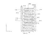
図2は、反応容器110の内部に配される内部構造物の一例を概略的に示す。図2においては、説明を簡単にすることを目的として、攪拌機120の描写が省略されている。図2に示されるとおり、重合装置100は、1以上のバッフル130として、バッフル232と、バッフル234と、バッフル236と、バッフル238とを備える。また、重合装置100は、1以上の蛇行冷却管140として、蛇行冷却管242と、蛇行冷却管244と、蛇行冷却管246と、蛇行冷却管248とを備える。同様に、重合装置100は、1以上の蛇行冷却管150として、蛇行冷却管252と、蛇行冷却管254と、蛇行冷却管256と、蛇行冷却管258とを備える。
FIG. 2 schematically shows an example of an internal structure arranged inside the reaction vessel 110. FIG. In FIG. 2, the depiction of stirrer 120 is omitted for the sake of clarity. As shown in FIG. 2 , polymerization apparatus 100 includes one or more baffles 130 , baffle 232 , baffle 234 , baffle 236 , and baffle 238 . Polymerization apparatus 100 also includes serpentine cooling pipe 242 , serpentine cooling pipe 244 , serpentine cooling pipe 246 , and serpentine cooling pipe 248 as one or more serpentine cooling pipes 140 . Similarly, polymerization apparatus 100 includes one or more serpentine cooling tubes 150 , serpentine cooling tube 252 , serpentine cooling tube 254 , serpentine cooling tube 256 , and serpentine cooling tube 258 .
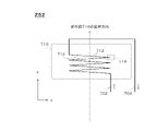
図3は、反応容器110の一例の概略断面図を示す。図3においては、説明を簡単にすることを目的として、蛇行冷却管140の描写が省略されている。また、説明を簡単にすることを目的として、バッフル232、バッフル234、バッフル236及びバッフル238の設置位置がデフォルメされている。
3 shows a schematic cross-sectional view of an example of the reaction vessel 110. FIG. In FIG. 3, the depiction of the serpentine cooling tubes 140 is omitted for ease of illustration. Also, the installation positions of baffle 232, baffle 234, baffle 236, and baffle 238 are distorted for the purpose of simplifying the explanation.
図3に示されるとおり、本実施形態において、反応容器110は、直胴部312と、第1鏡板314と、第2鏡板316と、台座318とを備える。本実施形態において、直胴部312は、円筒状の形状を有する。直胴部312の延伸方向(図中、z方向である。)の長さをHbとし、直胴部312の内径をDbとしたとき、直胴部312は、例えば、Hb/Dbの値が1.0~3.0となるように設計される。直胴部312は、Hb/Dbの値が1.5~2.5となるように設計されてよい。
As shown in FIG. 3 , in this embodiment, the reaction vessel 110 includes a straight body portion 312 , a first end plate 314 , a second end plate 316 and a pedestal 318 . In this embodiment, the straight body portion 312 has a cylindrical shape. When the length of the straight body portion 312 in the extending direction (the z-direction in the drawing) is Hb and the inner diameter of the straight body portion 312 is Db, the straight body portion 312 has a value of Hb/Db, for example. It is designed to be between 1.0 and 3.0. The straight body 312 may be designed to have a Hb/Db value of 1.5 to 2.5.
本実施形態において、第1鏡板314は、直胴部312の一方の端部に結合され、反応容器110の底板を構成する。本実施形態において、第2鏡板316は、直胴部312の他方の端部に結合され、反応容器110の天板を構成する。本実施形態において、台座318は、動力機構126を保持する。
In this embodiment, the first end plate 314 is coupled to one end of the straight body portion 312 and constitutes the bottom plate of the reaction vessel 110 . In this embodiment, the second end plate 316 is coupled to the other end of the straight body portion 312 and constitutes the top plate of the reaction vessel 110 . In this embodiment, pedestal 318 holds power mechanism 126 .
また、図3に示されるとおり、重合装置100の周囲には、冷媒の供給源から反応容器110に冷媒を供給するための冷媒供給配管332と、反応容器110から冷媒の供給源に、熱交換後の冷媒を返送するための冷媒返送配管334とが配される。また、図3に示された実施形態によれば、バッフル232及びバッフル234が連結部342により連結され、バッフル232から流出した冷媒が、バッフル234に流入可能に構成される。また、バッフル234及びバッフル236が連結部344により連結され、バッフル234から流出した冷媒が、バッフル236に流入可能に構成される。同様に、バッフル236及びバッフル238が連結部346により連結され、バッフル236から流出した冷媒が、バッフル238に流入可能に構成される。各バッフルの詳細は後述される。
Further, as shown in FIG. 3, around the polymerization apparatus 100, a refrigerant supply pipe 332 for supplying refrigerant from a refrigerant supply source to the reaction vessel 110 and a heat exchange pipe 332 from the reaction vessel 110 to the refrigerant supply source are provided. Refrigerant return piping 334 is arranged for returning the later refrigerant. Further, according to the embodiment shown in FIG. 3, the baffle 232 and the baffle 234 are connected by the connecting portion 342 so that the refrigerant flowing out of the baffle 232 can flow into the baffle 234 . Also, the baffle 234 and the baffle 236 are connected by a connecting portion 344 so that the refrigerant flowing out of the baffle 234 can flow into the baffle 236 . Similarly, the baffle 236 and the baffle 238 are connected by a connecting portion 346 so that the coolant that has flowed out of the baffle 236 can flow into the baffle 238 . Details of each baffle will be described later.
本実施形態によれば、冷媒供給配管332から反応容器110に供給された冷媒は、バッフル232に流入し、バッフル234、バッフル236及びバッフル238を通過して、冷媒返送配管334に排出される。なお、冷媒の流通方式は、本実施形態に限定されない。
According to this embodiment, the refrigerant supplied from the refrigerant supply pipe 332 to the reaction vessel 110 flows into the baffle 232, passes through the baffles 234, 236 and 238, and is discharged to the refrigerant return pipe 334. Note that the refrigerant distribution method is not limited to this embodiment.
例えば、他の実施形態において、冷媒供給配管332から反応容器110に供給された冷媒は、バッフル232に流入し、バッフル234を通過して、冷媒返送配管334に排出される。また、冷媒供給配管332から反応容器110に供給された冷媒は、バッフル238に流入し、バッフル236を通過して、冷媒返送配管334に排出される。さらに他の実施形態において、バッフル232、バッフル234、バッフル236及びバッフル238のそれぞれは、各バッフルに供給される冷媒の流量を独立して制御可能に構成される。
For example, in another embodiment, refrigerant supplied to the reaction vessel 110 from the refrigerant supply pipe 332 flows into the baffle 232, passes through the baffle 234, and is discharged to the refrigerant return pipe 334. Also, the coolant supplied from the coolant supply pipe 332 to the reaction vessel 110 flows into the baffle 238 , passes through the baffle 236 , and is discharged to the coolant return pipe 334 . In yet another embodiment, each of baffle 232, baffle 234, baffle 236, and baffle 238 are configured to independently control the flow rate of refrigerant supplied to each baffle.
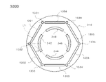
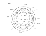
図4は、反応容器110の一例の概略平面図を示す。本実施形態において、(i)バッフル232、バッフル234、バッフル236及びバッフル238と、(ii)蛇行冷却管242、蛇行冷却管244、蛇行冷却管246及び蛇行冷却管248と、(iii)蛇行冷却管252、蛇行冷却管254、蛇行冷却管256及び蛇行冷却管258とが、同心円状に配される。
4 shows a schematic plan view of an example of the reaction vessel 110. FIG. In this embodiment, (i) baffle 232, baffle 234, baffle 236 and baffle 238, (ii) serpentine cooling tube 242, serpentine cooling tube 244, serpentine cooling tube 246 and serpentine cooling tube 248, and (iii) serpentine cooling Tube 252, serpentine cooling tube 254, serpentine cooling tube 256 and serpentine cooling tube 258 are arranged concentrically.
本実施形態において、蛇行冷却管242と、蛇行冷却管244と、蛇行冷却管246と、蛇行冷却管248とが、略同一円周上に配される。また、本実施形態において、(i)バッフル232、バッフル234、バッフル236及びバッフル238と、(ii)蛇行冷却管252、蛇行冷却管254、蛇行冷却管256及び蛇行冷却管258は、略同一円周上に配される。
In this embodiment, the meandering cooling pipe 242, the meandering cooling pipe 244, the meandering cooling pipe 246, and the meandering cooling pipe 248 are arranged on substantially the same circumference. Further, in the present embodiment, (i) baffle 232, baffle 234, baffle 236, and baffle 238, and (ii) meandering cooling pipe 252, meandering cooling pipe 254, meandering cooling pipe 256, and meandering cooling pipe 258 are substantially circular. distributed around the circumference.
つまり、直胴部312の特定の位置における横断面において、バッフル232、バッフル234、バッフル236及びバッフル238の横断面の中心と、蛇行冷却管252、蛇行冷却管254、蛇行冷却管256及び蛇行冷却管258の横断面の中心とが、略同一円周上に配される。直胴部312の特定の位置における横断面は、直胴部312の延伸方向(図中、z方向である。)に垂直な面(図中、xy平面である。)であって、蛇行冷却管252、蛇行冷却管254、蛇行冷却管256及び蛇行冷却管258の中心を通る平面で、反応容器110を切断した断面であってよい。この場合、横断面における各配管の幅は、各配管の直径に一致する。
That is, in a cross-section at a particular location of the body 312, the center of the cross-section of baffle 232, baffle 234, baffle 236 and baffle 238 and the center of the cross-section of serpentine cooling tube 252, serpentine cooling tube 254, serpentine cooling tube 256 and serpentine cooling The center of the cross section of the tube 258 is arranged on substantially the same circumference. A cross section at a specific position of the straight body portion 312 is a plane (xy plane in the figure) perpendicular to the extending direction (z direction in the figure) of the straight body portion 312, and the meandering cooling is performed. A plane passing through the centers of tube 252 , serpentine cooling tube 254 , serpentine cooling tube 256 and serpentine cooling tube 258 may be a cross-section through reaction vessel 110 . In this case, the width of each pipe in cross section corresponds to the diameter of each pipe.
本実施形態において、バッフル232、バッフル234、バッフル236及びバッフル238は、反応容器110の中心軸の周りに略対称的な位置に配置される。蛇行冷却管242、蛇行冷却管244、蛇行冷却管246及び蛇行冷却管248は、反応容器110の中心軸の周りに略対称的な位置に配置される。蛇行冷却管252、蛇行冷却管254、蛇行冷却管256及び蛇行冷却管258は、反応容器110の中心軸の周りに略対称的な位置に配置される。
In this embodiment, the baffle 232 , the baffle 234 , the baffle 236 and the baffle 238 are arranged at substantially symmetrical positions around the central axis of the reaction vessel 110 . Serpentine cooling pipe 242 , serpentine cooling pipe 244 , serpentine cooling pipe 246 , and serpentine cooling pipe 248 are arranged at substantially symmetrical positions around the central axis of reaction vessel 110 . Serpentine cooling pipe 252 , serpentine cooling pipe 254 , serpentine cooling pipe 256 , and serpentine cooling pipe 258 are arranged at substantially symmetrical positions around the central axis of reaction vessel 110 .
図4に示されるとおり、蛇行冷却管252は、バッフル232と、バッフル234との間の位置に配される。蛇行冷却管254は、バッフル234と、バッフル236との間の位置に配される。蛇行冷却管256は、バッフル236と、バッフル238との間の位置に配される。蛇行冷却管258は、バッフル238と、バッフル232との間の位置に配される。蛇行冷却管252、蛇行冷却管254、蛇行冷却管256及び蛇行冷却管258の外周の直径は、バッフル232、バッフル234、バッフル236及びバッフル238の幅Bwより小さくてもよい。
As shown in FIG. 4, serpentine cooling tubes 252 are positioned between baffles 232 and 234 . A serpentine cooling tube 254 is positioned between baffle 234 and baffle 236 . A serpentine cooling tube 256 is positioned between baffle 236 and baffle 238 . A serpentine cooling tube 258 is positioned between baffle 238 and baffle 232 . The diameter of the perimeter of serpentine cooling tube 252 , serpentine cooling tube 254 , serpentine cooling tube 256 and serpentine cooling tube 258 may be less than the width Bw of baffle 232 , baffle 234 , baffle 236 and baffle 238 .
本実施形態において、蛇行冷却管242、蛇行冷却管244、蛇行冷却管246及び蛇行冷却管248が配される円の直径は、蛇行冷却管252、蛇行冷却管254、蛇行冷却管256及び蛇行冷却管258が配される円の直径よりも小さい。本実施形態によれば、反応容器110の直胴部312の直径方向において、蛇行冷却管が多段に配され得る。これにより、例えば、反応容器110の内部にリング状又は螺旋状の大きな配管が配置される場合と比較して、内部構造物の配置の自由度が向上する。その結果、冷却効率に優れた重合装置100が作製され得る。
In this embodiment, the diameter of the circle in which serpentine cooling pipe 242, serpentine cooling pipe 244, serpentine cooling pipe 246, and serpentine cooling pipe 248 are arranged is equal to smaller than the diameter of the circle in which tube 258 is arranged. According to this embodiment, meandering cooling pipes can be arranged in multiple stages in the diametrical direction of the straight body portion 312 of the reaction vessel 110 . This improves the degree of freedom in arranging the internal structure compared to, for example, the case where a large ring-shaped or spiral pipe is arranged inside the reaction vessel 110 . As a result, the polymerization apparatus 100 with excellent cooling efficiency can be produced.
蛇行冷却管242、蛇行冷却管244、蛇行冷却管246及び蛇行冷却管248の外周が配される仮想的な円の直径D1の大きさは、特に限定されるものではないが、攪拌翼124の回転領域の直径D2より大きいことが好ましい。D1/D2は、1.1以上であることが好ましく、1.2以上であることがより好ましい。
The diameter D1 of the virtual circle in which the outer peripheries of the meandering cooling pipe 242, the meandering cooling pipe 244, the meandering cooling pipe 246, and the meandering cooling pipe 248 are arranged is not particularly limited. It is preferably larger than the diameter D2 of the rotating area. D1/D2 is preferably 1.1 or more, more preferably 1.2 or more.
本実施形態において、蛇行冷却管252、蛇行冷却管254、蛇行冷却管256及び蛇行冷却管258のそれぞれと、直胴部312の内面との距離は、全てL1である。同様に、蛇行冷却管242、蛇行冷却管244、蛇行冷却管246及び蛇行冷却管248のそれぞれと、直胴部312の内面との距離は、全てL2である。図4に示されるとおり、本実施形態において、L2>L1である。
In this embodiment, the distance between each of the meandering cooling pipes 252, 254, 256 and 258 and the inner surface of the straight body portion 312 is L1. Similarly, the distances between each of meandering cooling pipe 242, meandering cooling pipe 244, meandering cooling pipe 246, and meandering cooling pipe 248 and the inner surface of straight body portion 312 are all L2. As shown in FIG. 4, in this embodiment, L2>L1.
上記のL1及びL2の大きさは特に限定されるものではないが、L1は、各蛇行冷却管の外周と、直胴部312の内面との距離が40mm以上となるように設定されることが好ましい。なお、L1が40mm以上となるように設定されてもよい。上記の距離又はL1が40mm未満の場合、反応容器110の内部の気液界面付近において、反応容器110の内壁面と、蛇行冷却管150との間に重合体のスケールが付着しやすくなる場合がある。
Although the sizes of L1 and L2 are not particularly limited, L1 may be set so that the distance between the outer circumference of each meandering cooling pipe and the inner surface of the straight body portion 312 is 40 mm or more. preferable. Note that L1 may be set to 40 mm or more. If the distance or L1 is less than 40 mm, polymer scale may easily adhere between the inner wall surface of the reaction vessel 110 and the meandering cooling pipe 150 near the gas-liquid interface inside the reaction vessel 110. be.
同様に、蛇行冷却管242と、蛇行冷却管252との距離Pcは、40mm以上であることが好ましい。距離Pcは、例えば、上記の横断面において、蛇行冷却管242の外周と、蛇行冷却管252の外周との距離の最小値を算出することで決定される。Pcが40mm未満の場合、重合体のスケールが付着しやすくなる場合がある。
Similarly, the distance Pc between the meandering cooling pipe 242 and the meandering cooling pipe 252 is preferably 40 mm or more. The distance Pc is determined, for example, by calculating the minimum value of the distance between the outer circumference of the meandering cooling pipe 242 and the outer circumference of the meandering cooling pipe 252 in the cross section. When Pc is less than 40 mm, polymer scale may easily adhere.
特定の蛇行冷却管と、直胴部312の内面との距離は、直胴部312の延伸方向に垂直、且つ、当該特定の蛇行冷却管の中心を通る断面における、両者の最短距離として決定されてよい。各蛇行冷却管と、直胴部312の内面との距離は、例えば、上記の横断面において、各蛇行冷却管の延伸方向に沿った中心線と、直胴部312の内面との距離の最小値を算出することで決定される。なお、本実施形態において、上記の各蛇行冷却管の延伸方向に沿った中心線は、円弧状に湾曲している。上記の距離の詳細は後述される。
The distance between the specific meandering cooling pipe and the inner surface of the straight body portion 312 is determined as the shortest distance between the two in a cross section perpendicular to the extending direction of the straight body portion 312 and passing through the center of the specific meandering cooling pipe. you can The distance between each meandering cooling pipe and the inner surface of the straight body portion 312 is, for example, the minimum distance between the center line along the extending direction of each meandering cooling pipe and the inner surface of the straight body portion 312 in the above cross section. Determined by calculating the value. In addition, in the present embodiment, the center line along the extending direction of each meandering cooling pipe is curved in an arc shape. Details of the above distances will be described later.
図4に示されるとおり、直胴部312の特定の位置における横断面において、蛇行冷却管242、蛇行冷却管244、蛇行冷却管246及び蛇行冷却管254の横断面は、円弧状の形状を有する。同様に、蛇行冷却管252、蛇行冷却管254、蛇行冷却管256及び蛇行冷却管258の横断面は、円弧状の形状を有する。蛇行冷却管242、蛇行冷却管244、蛇行冷却管246及び蛇行冷却管254の横断面の形状と、蛇行冷却管252、蛇行冷却管254、蛇行冷却管256及び蛇行冷却管258の横断面の形状とは、相似形であってよい。例えば、蛇行冷却管242及び蛇行冷却管252の横断面が円弧状の形状を有する場合、蛇行冷却管242の円弧の中心角と、蛇行冷却管252の円弧の中心角とが略同一であってよい。蛇行冷却管244及び蛇行冷却管254、蛇行冷却管246及び蛇行冷却管256、並びに、蛇行冷却管248及び蛇行冷却管258についても同様であってよい。
As shown in FIG. 4, in a cross-section at a particular position of the straight body 312, the cross-sections of the serpentine cooling tubes 242, 244, 246, and 254 have an arcuate shape. . Similarly, the cross-sections of serpentine cooling tube 252, serpentine cooling tube 254, serpentine cooling tube 256, and serpentine cooling tube 258 have an arcuate shape. Cross-sectional shape of serpentine cooling tube 242, serpentine cooling tube 244, serpentine cooling tube 246, and serpentine cooling tube 254; may be analogous. For example, when the meandering cooling pipe 242 and the meandering cooling pipe 252 have arcuate cross sections, the central angle of the arc of the meandering cooling pipe 242 and the central angle of the arc of the meandering cooling pipe 252 are substantially the same. good. The same may be true for serpentine cooling tubes 244 and 254 , serpentine cooling tubes 246 and 256 , and serpentine cooling tubes 248 and 258 .
上記の蛇行冷却管の形状が円弧上である場合、円弧の中心角の大きさは270度以下であってよい。円弧の中心角の大きさは240度以下であってもよく、210度以下であってもよく、180度以下であってもよく、150度以下であってもよく、120度以下であってもよく、90度以下であってもよく、60度以下であってもよい。
When the shape of the meandering cooling pipe is an arc, the central angle of the arc may be 270 degrees or less. The central angle of the arc may be 240 degrees or less, 210 degrees or less, 180 degrees or less, 150 degrees or less, or 120 degrees or less. may be less than or equal to 90 degrees, or less than or equal to 60 degrees.
また、本実施形態において、蛇行冷却管252、蛇行冷却管254、蛇行冷却管256及び蛇行冷却管258の少なくとも1つの延伸方向の長さ(図中の円弧の長さである。)は、直胴部312の内周の長さの2/3よりも小さい。上記の延伸方向の長さ(図中の円弧の長さである。)は、直胴部312の内周の長さの1/2以下であってもよく、直胴部312の内周の長さの1/2より小さくてもよく、直胴部312の内周の長さの1/3以下であってもよく、直胴部312の内周の長さの1/3より小さくてもよく、直胴部312の内周の長さの1/4以下であってもよく、直胴部312の内周の長さの1/4より小さくてもよく、直胴部312の内周の長さの1/6以下であってもよく、直胴部312の内周の長さの1/6より小さくてもよい。
Further, in the present embodiment, the length in the extending direction of at least one of the meandering cooling pipes 252, 254, 256, and 258 (the length of the arc in the figure) is straight. It is smaller than 2/3 of the length of the inner circumference of the barrel 312 . The length in the stretching direction (the length of the arc in the figure) may be 1/2 or less of the length of the inner circumference of the straight body portion 312. It may be less than 1/2 of the length, may be 1/3 or less of the length of the inner periphery of the straight body portion 312, or be less than 1/3 of the length of the inner periphery of the straight body portion 312. It may be 1/4 or less of the length of the inner circumference of the straight body portion 312, or it may be less than 1/4 of the length of the inner circumference of the straight body portion 312. It may be 1/6 or less of the length of the circumference, or may be smaller than 1/6 of the length of the inner circumference of the straight body portion 312 .
上述されたとおり、特開平7-233206号公報に記載されたコイル状冷却管は、略円形の形状を有する。つまり、冷却管の円弧の中心角は、ほぼ360度である。そのため、バッフルと、コイル状冷却管とを略同一円周上に配置することができない。これに対して、本実施形態によれば、蛇行冷却管140よりも直胴部312の内側に近い位置に配される1以上の蛇行冷却管150のうちの少なくとも1つが、上記のような構成を有することにより、2つのバッフル130の間に配され得る。これにより、蛇行冷却管150が重合装置100の混合性能に与える影響をより小さくしつつ、装置全体の伝熱面積を増加させることができる。
As described above, the coiled cooling pipe described in JP-A-7-233206 has a substantially circular shape. That is, the central angle of the arc of the cooling pipe is approximately 360 degrees. Therefore, the baffle and the coiled cooling pipe cannot be arranged on substantially the same circumference. In contrast, according to the present embodiment, at least one of the one or more meandering cooling pipes 150 arranged closer to the inner side of the straight body portion 312 than the meandering cooling pipes 140 has the above configuration. can be placed between the two baffles 130 by having a As a result, the heat transfer area of the entire apparatus can be increased while reducing the influence of the meandering cooling pipe 150 on the mixing performance of the polymerization apparatus 100 .
直胴部312の内面は、反応器の内壁面の一例であってよい。蛇行冷却管252は、反応器の内壁面からの距離が最も小さな第1冷却配管の一例であってよい。蛇行冷却管254は、反応器の内壁面からの距離が最も小さな第1冷却配管の一例であってよい。蛇行冷却管256は、反応器の内壁面からの距離が最も小さな第1冷却配管の一例であってよい。蛇行冷却管258は、反応器の内壁面からの距離が最も小さな第1冷却配管の一例であってよい。
The inner surface of the straight body part 312 may be an example of the inner wall surface of the reactor. The serpentine cooling pipe 252 may be an example of a first cooling pipe with the smallest distance from the inner wall surface of the reactor. The serpentine cooling pipe 254 may be an example of a first cooling pipe with the smallest distance from the inner wall surface of the reactor. Serpentine cooling pipe 256 may be an example of a first cooling pipe that is the smallest distance from the inner wall surface of the reactor. Serpentine cooling pipe 258 may be an example of a first cooling pipe that is the smallest distance from the inner wall surface of the reactor.
(別実施形態の一例)
本実施形態においては、直胴部312の中心から外側に向かって、蛇行冷却管が2重に多重化されている場合を例として、重合装置100の一例が説明された。しかしながら、重合装置100は、本実施形態に限定されない。他の実施形態において、直胴部312の中心から外側に向かって、蛇行冷却管が3重以上に多重化されていてもよい。直胴部312の中心から外側に向かって、蛇行冷却管が2~5重に多重化されていることが好ましい。
(An example of another embodiment)
In the present embodiment, an example of the polymerization apparatus 100 has been described, taking as an example the case where the meandering cooling pipes are doubled from the center of the straight body portion 312 toward the outside. However, the polymerization device 100 is not limited to this embodiment. In another embodiment, three or more meandering cooling pipes may be multiplexed outward from the center of the straight body portion 312 . It is preferable that the meandering cooling pipes are multiplexed two to five times from the center of the straight body portion 312 toward the outside.
図5は、バッフル232の内部構造の一例を概略的に示す。なお、バッフル234、バッフル236及びバッフル238も、バッフル232と同様の内部構造を有してよい。本実施形態において、バッフル232は、内管510と、外管520とを含む二重管構造を有する。バッフル232は、内管510の内部に冷媒を流入させる流入口512と、外管520の内部から冷媒を流出させる流出口522とを有する。
FIG. 5 schematically shows an example of the internal structure of the baffle 232. Note that baffle 234 , baffle 236 and baffle 238 may also have internal structures similar to baffle 232 . In this embodiment, the baffle 232 has a double tube structure including an inner tube 510 and an outer tube 520 . The baffle 232 has an inlet 512 through which the coolant flows into the inner tube 510 and an outlet 522 through which the coolant flows out from the outer tube 520 .
本実施形態において、バッフル232の流入口512は、配管532及び流量調整弁542を介して、冷媒供給配管332に接続される。これにより、流量調整弁542の開度が調整されることで、バッフル232に流入する冷媒の流量が調整される。同様に、バッフル234の流入口512は、配管534及び流量調整弁544を介して、冷媒供給配管332に接続される。
In this embodiment, the inflow port 512 of the baffle 232 is connected to the coolant supply pipe 332 via the pipe 532 and the flow control valve 542 . Thereby, the flow rate of the refrigerant flowing into the baffle 232 is adjusted by adjusting the opening degree of the flow rate adjustment valve 542 . Similarly, inlet 512 of baffle 234 is connected to refrigerant supply line 332 via line 534 and flow control valve 544 .
本実施形態において、バッフル232の流出口522は、連結部342を介して、冷媒返送配管334及びバッフル234に接続される。図5に示されるとおり、本実施形態において、連結部342は、配管552と、流量調整弁554と、配管556と、流量調整弁558とを有する。
In this embodiment, the outflow port 522 of the baffle 232 is connected to the refrigerant return pipe 334 and the baffle 234 via the connecting portion 342 . As shown in FIG. 5 , in this embodiment, the connecting portion 342 has a pipe 552 , a flow control valve 554 , a pipe 556 and a flow control valve 558 .
配管552は、流出口522と冷媒返送配管334とを接続する。流量調整弁554は、配管552の途中に配され、配管552を流れる冷媒の流量を調整する。配管556は、流出口522とバッフル234とを接続する。より具体的には、配管556は、配管552上の位置であって、流量調整弁554及びバッフル232の流出口522の間の位置と、配管534上の位置であって、流量調整弁544及びバッフル234の流入口512の間の位置とを接続する。流量調整弁558は、配管556の途中に配され、配管556を流れる冷媒の流量を調整する。
A pipe 552 connects the outlet 522 and the refrigerant return pipe 334 . The flow rate adjustment valve 554 is arranged in the middle of the pipe 552 and adjusts the flow rate of the refrigerant flowing through the pipe 552 . A pipe 556 connects the outlet 522 and the baffle 234 . More specifically, piping 556 is located on piping 552 at a location between flow regulating valve 554 and outlet 522 of baffle 232, and on piping 534 at a location between flow regulating valves 544 and 522 of baffle 232. locations between the inlets 512 of the baffle 234. A flow rate adjustment valve 558 is arranged in the middle of the pipe 556 and adjusts the flow rate of the refrigerant flowing through the pipe 556 .
(別実施形態の一例)
本実施形態においては、バッフル232が二重管構造を有し、バッフル232の下方から流入した冷媒がバッフル232の下方から流出し、バッフル234の下方からバッフル234に流入する場合を例として、重合装置100の一例が説明された。しかしながら、重合装置100は本実施形態に限定されない。
(An example of another embodiment)
In this embodiment, the baffle 232 has a double tube structure, and the refrigerant that has flowed in from below the baffle 232 flows out from below the baffle 232 and flows into the baffle 234 from below. An example of the device 100 has been described. However, the polymerization device 100 is not limited to this embodiment.
他の実施形態において、バッフル232の下方から流入した冷媒がバッフル232の上方から流出し、バッフル234の上方からバッフル234に流入するように、配管が構成されてよい。さらに他の実施形態において、バッフル232は、一重管であってもよい。
In another embodiment, the piping may be configured so that the refrigerant that has flowed in from below the baffle 232 flows out from above the baffle 232 and flows into the baffle 234 from above. In still other embodiments, baffle 232 may be a single tube.
図6は、蛇行冷却管252の構造の一例を概略的に示す。なお、他の蛇行冷却管140及び蛇行冷却管150も、蛇行冷却管252と同様の構造を有してよい。図6に示されるとおり、蛇行冷却管252は、繰り返し屈曲しながらz方向に延伸する。本実施形態において、蛇行冷却管252は、蛇行部610を有する。蛇行部610は、複数の延伸部612と、1以上の屈曲部614とを有する。
6 schematically shows an example of the structure of the meandering cooling pipe 252. FIG. Note that the other serpentine cooling pipes 140 and 150 may also have a structure similar to that of the serpentine cooling pipe 252 . As shown in FIG. 6, the serpentine cooling tube 252 extends in the z-direction with repeated bends. In this embodiment, serpentine cooling tube 252 has a serpentine portion 610 . The serpentine portion 610 has a plurality of extensions 612 and one or more bends 614 .
図6に関連して説明される蛇行冷却管252において、蛇行部610は、15個の延伸部612と、14個の屈曲部614とを有する。単一の蛇行部610における延伸部612の個数は、段数と称される場合がある。図2に示されるとおり、本実施形態においては、蛇行冷却管252が、延伸部612においてxy平面上で延伸し、屈曲部614においてz方向に屈曲する。
In the serpentine cooling tube 252 described in connection with FIG. The number of extensions 612 in a single serpentine 610 is sometimes referred to as the number of steps. As shown in FIG. 2, in this embodiment, serpentine cooling tube 252 extends in the xy plane at extension 612 and bends in the z-direction at bend 614 .
本実施形態において、複数の延伸部612のそれぞれは、略同一の平面上で延伸する。例えば、延伸部612が同一平面上で延伸するように設計されている場合であっても、製作に伴う誤差、据え付けに伴う誤差などにより、延伸部612が完全に同一の平面上で延伸していないこともあり得る。このような場合、延伸部612は、略同一の平面上で延伸していると見做してよい。なお、延伸部612が略同一の平面上で延伸する場合は、上記の例に限定されないことに留意されたい。
In this embodiment, each of the plurality of extending portions 612 extends on substantially the same plane. For example, even if the extending portions 612 are designed to extend on the same plane, the extending portions 612 may not extend completely on the same plane due to manufacturing errors, installation errors, or the like. It may not be. In such a case, the extensions 612 may be considered to extend substantially on the same plane. It should be noted that the case where the extending portions 612 extend on substantially the same plane is not limited to the above example.
この点で、蛇行冷却管252は、螺旋状の冷却配管と相違する。蛇行冷却管252が蛇行して延伸することにより、冷却配管が螺旋状に延伸する場合と比較して、設置面積あたりの表面積が大きくなり得る。
In this respect, the meandering cooling pipe 252 is different from the spiral cooling pipe. The meandering extension of the serpentine cooling pipe 252 can increase the surface area per installation area compared to the case where the cooling pipe extends in a spiral shape.
図4に関連して説明されたとおり、本実施形態において、複数の延伸部612のそれぞれは、xy平面上で湾曲しながら延伸する。複数の延伸部612のそれぞれの延伸方向の長さPLは同一であってもよく、少なくとも2つの延伸部612の延伸方向の長さが異なってもよい。本実施形態において、PLは、延伸部612のxy平面上での長さである。PLは、延伸部612の延伸方向に略垂直な面(この場合、z方向に略平行な面である。)により延伸部612を切断した場合における延伸部612の断面の中心をとおるxy平面における、延伸部612の長さであってよい。
As described with reference to FIG. 4, in this embodiment, each of the plurality of extending portions 612 extends while curving on the xy plane. The length PL in the extending direction of each of the plurality of extending portions 612 may be the same, or the length in the extending direction of at least two extending portions 612 may be different. In this embodiment, PL is the length of the extended portion 612 on the xy plane. PL is the xy plane passing through the center of the cross section of the extending portion 612 when the extending portion 612 is cut along a plane substantially perpendicular to the extending direction of the extending portion 612 (in this case, a plane substantially parallel to the z-direction). , the length of extension 612 .
上述されたとおり、PLは、直胴部312の内周の長さの2/3よりも小さくてよい。この点で、蛇行冷却管252は、特開平7-233206号公報に記載されたコイル状冷却管と相違する。
As described above, PL may be smaller than 2/3 of the length of the inner circumference of straight body portion 312 . In this respect, the meandering cooling pipe 252 is different from the coiled cooling pipe described in JP-A-7-233206.
単一の蛇行部610において、複数の延伸部612のうち、1/2を超える個数の延伸部612のPLが、直胴部312の内周の長さの2/3よりも小さくてよい。上記のPLは、直胴部312の内周の長さの1/2以下であってもよく、直胴部312の内周の長さの1/2より小さくてもよく、直胴部312の内周の長さの1/3以下であってもよく、直胴部312の内周の長さの1/3より小さくてもよく、直胴部312の内周の長さの1/4以下であってもよく、直胴部312の内周の長さの1/4より小さくてもよく、直胴部312の内周の長さの1/6以下であってもよく、直胴部312の内周の長さの1/6より小さくてもよい。
In the single meandering portion 610 , the PL of more than 1/2 of the plurality of extending portions 612 may be smaller than 2/3 of the length of the inner circumference of the straight body portion 312 . The above PL may be 1/2 or less of the length of the inner circumference of the straight body portion 312, or may be smaller than 1/2 of the length of the inner circumference of the straight body portion 312. may be 1/3 or less of the length of the inner circumference of the straight body portion 312, or less than 1/3 of the length of the inner circumference of the straight body portion 312, or 1/3 of the length of the inner circumference of the straight body portion 312. It may be 4 or less, it may be less than 1/4 of the length of the inner circumference of the straight body portion 312, or it may be 1/6 or less of the length of the inner circumference of the straight body portion 312. It may be smaller than 1/6 of the length of the inner circumference of the body portion 312 .
複数の延伸部612のうち、2/3を超える個数の延伸部612のPLが、直胴部312の内周の長さの2/3よりも小さくてよい。上記のPLは、直胴部312の内周の長さの1/2以下であってもよく、直胴部312の内周の長さの1/2より小さくてもよく、直胴部312の内周の長さの1/3以下であってもよく、直胴部312の内周の長さの1/3より小さくてもよく、直胴部312の内周の長さの1/4以下であってもよく、直胴部312の内周の長さの1/4より小さくてもよく、直胴部312の内周の長さの1/6以下であってもよく、直胴部312の内周の長さの1/6より小さくてもよい。
Of the plurality of extending portions 612 , the PL of more than 2/3 of the extending portions 612 may be smaller than 2/3 of the length of the inner circumference of the straight body portion 312 . The above PL may be 1/2 or less of the length of the inner circumference of the straight body portion 312, or may be smaller than 1/2 of the length of the inner circumference of the straight body portion 312. may be 1/3 or less of the length of the inner circumference of the straight body portion 312, or less than 1/3 of the length of the inner circumference of the straight body portion 312, or 1/3 of the length of the inner circumference of the straight body portion 312. It may be 4 or less, it may be less than 1/4 of the length of the inner circumference of the straight body portion 312, or it may be 1/6 or less of the length of the inner circumference of the straight body portion 312. It may be smaller than 1/6 of the length of the inner circumference of the body portion 312 .
一実施形態において、複数の延伸部612の少なくとも1つは、略同一の平面上で湾曲して延伸する。例えば、複数の延伸部612の少なくとも1つは、xy平面上に仮想的に配された円弧又は楕円弧に沿って延伸する。他の実施形態において、複数の延伸部612の少なくとも1つは、略同一の平面上で直線状に延伸する。
In one embodiment, at least one of the plurality of extensions 612 curves and extends on substantially the same plane. For example, at least one of the plurality of extending portions 612 extends along a circular arc or elliptical arc virtually arranged on the xy plane. In other embodiments, at least one of the plurality of extensions 612 extends linearly in substantially the same plane.
本実施形態において、複数の延伸部612の2つが、略平行な2つの平面上で延伸する。例えば、隣接する2つの延伸部612が、略平行な2つの平面上で延伸する。これにより、梯子状に延伸する蛇行部610が得られる。他の実施形態において、複数の延伸部612の2つが、平行でない2つの平面上で延伸してよい。例えば、隣接する2つの延伸部612が、交差する2つの平面上で延伸する。これにより、ジグザグ状に延伸する蛇行部610が得られる。
In this embodiment, two of the plurality of extending portions 612 extend on two substantially parallel planes. For example, two adjacent extensions 612 extend in two substantially parallel planes. Thereby, a meandering portion 610 extending like a ladder is obtained. In other embodiments, two of the plurality of extensions 612 may extend on two non-parallel planes. For example, two adjacent extensions 612 extend on two intersecting planes. Thereby, a meandering portion 610 extending in a zigzag shape is obtained.
本実施形態において、1以上の屈曲部614のそれぞれは、隣接する2つの延伸部612の端部を連結する。図6に示された実施形態において、1以上の屈曲部614のそれぞれは、z方向に屈曲する部分を含む。これにより、蛇行部610は、屈曲しながらz方向に延伸する。屈曲部614の形状は、特に限定されない。屈曲部614を蛇行冷却管252の延伸方向に平行な面であって、屈曲部614の中心を通る面で切断した断面(縦断面と称される場合がある。)の形状は、連続的に屈曲する形状を有してもよく、複数の直線により構成される形状を有してもよい。連続的に屈曲する形状としては、円弧状又は楕円弧状が例示される。屈曲部614は、連続的に屈曲する形状を有する部分と、1以上の直線により構成される形状を有する部分とにより構成されていてもよい。
In this embodiment, each of the one or more bends 614 connects the ends of two adjacent extensions 612 . In the embodiment shown in FIG. 6, each of the one or more bends 614 includes a portion that bends in the z-direction. Thereby, the meandering portion 610 extends in the z-direction while bending. The shape of the bent portion 614 is not particularly limited. A cross section (sometimes referred to as a longitudinal section) obtained by cutting the bent portion 614 along a plane parallel to the extending direction of the meandering cooling pipe 252 and passing through the center of the bent portion 614 has a continuous shape. It may have a curved shape, or may have a shape composed of a plurality of straight lines. A circular arc shape or an elliptical arc shape is exemplified as the continuously curved shape. The bent portion 614 may be composed of a portion having a continuously bent shape and a portion having a shape composed of one or more straight lines.
蛇行冷却管252の流路の直径は特に限定されるものではないが、上記の直径は、10~200mmであることが好ましい。単一の蛇行冷却管252に含まれる延伸部612の個数(段数と称される場合がある。)は特に限定されるものではないが、上記の段数は、2~70であることが好ましい。隣接する2つの延伸部612の距離(ピッチと称される場合がある。)Ppの大きさは特に限定されるものではないが、上記のPpは60mm以上であることが好ましい。Ppが60mm未満の場合、重合体のスケールが付着しやすくなる場合がある。
Although the diameter of the passage of the meandering cooling pipe 252 is not particularly limited, the above diameter is preferably 10 to 200 mm. The number of extending portions 612 (sometimes referred to as the number of stages) included in a single meandering cooling pipe 252 is not particularly limited, but the number of stages is preferably 2-70. The distance (sometimes referred to as pitch) Pp between two adjacent extending portions 612 is not particularly limited, but the above Pp is preferably 60 mm or more. When Pp is less than 60 mm, polymer scale may easily adhere.
(別実施形態の一例)
(an example of another embodiment)
本実施形態においては、蛇行冷却管252が屈曲しながらz方向に延伸する場合を例として、蛇行冷却管252の一例が説明された。しかしながら、蛇行冷却管252は、本実施形態に限定されない。他の実施形態において、蛇行冷却管252は、屈曲しながらx方向又はy方向に延伸してもよい。
In the present embodiment, an example of the meandering cooling pipe 252 has been described, taking as an example the case where the meandering cooling pipe 252 extends in the z-direction while being bent. However, the serpentine cooling tube 252 is not limited to this embodiment. In other embodiments, the serpentine cooling tube 252 may extend in the x-direction or the y-direction while bending.
本実施形態においては、延伸部612がxy平面上で延伸し、屈曲部614がz方向に屈曲する場合を例として、蛇行冷却管252の一例が説明された。しかしながら、蛇行冷却管252は、本実施形態に限定されない。他の実施形態において、屈曲部614は、xy平面上で屈曲する第1屈曲部材と、z方向に屈曲する第2屈曲部材とを有してもよい。
In the present embodiment, an example of the meandering cooling pipe 252 has been described, taking as an example the case where the extending portion 612 extends on the xy plane and the bending portion 614 bends in the z direction. However, the serpentine cooling tube 252 is not limited to this embodiment. In another embodiment, the bending portion 614 may have a first bending member that bends on the xy plane and a second bending member that bends in the z-direction.
図7は、蛇行冷却管252の構造の他の例を概略的に示す。本実施形態において、蛇行冷却管252は、ジグザグ状に屈曲しながら、z方向に延伸する。本実施形態において、蛇行冷却管252は、供給配管702と、流出配管704と、蛇行部710とを備える。本実施形態において、蛇行部710は、複数の延伸部712と、1以上の屈曲部714とを有する。
FIG. 7 schematically shows another example of the structure of the meandering cooling pipe 252. FIG. In this embodiment, the meandering cooling pipe 252 extends in the z-direction while bending in a zigzag manner. In this embodiment, serpentine cooling pipe 252 comprises supply pipe 702 , outlet pipe 704 , and serpentine 710 . In this embodiment, the serpentine portion 710 has a plurality of extensions 712 and one or more bends 714 .
供給配管702は、蛇行部710に供給される冷媒を流通させる。流出配管704は、蛇行部710から流出された冷媒を流通させる。蛇行部710は、繰り返し屈曲しながらz方向に延伸する。
The supply pipe 702 circulates the refrigerant supplied to the meandering portion 710 . The outflow pipe 704 allows the refrigerant flowing out from the meandering portion 710 to flow. The meandering portion 710 extends in the z-direction while repeatedly bending.
図7に関連して説明される蛇行冷却管252は、複数の延伸部712が略平行に配されていない点で、図6に関連して説明された蛇行冷却管252と相違する。上記の相違点以外の特徴について、図7に関連して説明される蛇行冷却管252は、図6に関連して説明された蛇行冷却管252と同様の構成を有してよい。
The serpentine cooling pipe 252 described with reference to FIG. 7 differs from the serpentine cooling pipe 252 described with reference to FIG. 6 in that the plurality of extensions 712 are not arranged substantially parallel. Other than the differences noted above, the serpentine cooling tube 252 described in connection with FIG. 7 may have a similar configuration to the serpentine cooling tube 252 described in connection with FIG.
図8は、蛇行冷却管252の構造の他の例を概略的に示す。本実施形態において、蛇行冷却管252は、供給配管702と、流出配管704と、蛇行部810とを備える。本実施形態において、蛇行部810は、蛇行部812と、連結部822と、蛇行部814と、連結部824と、蛇行部816とを有する。
FIG. 8 schematically shows another example of the structure of the meandering cooling pipe 252. FIG. In this embodiment, serpentine cooling pipe 252 comprises supply pipe 702 , outlet pipe 704 , and serpentine 810 . In this embodiment, meandering portion 810 includes meandering portion 812 , connecting portion 822 , meandering portion 814 , connecting portion 824 , and meandering portion 816 .
本実施形態において、蛇行部810は、繰り返し屈曲しながらz方向に延伸する。本実施形態において、蛇行部812は、繰り返し屈曲しながらx方向に延伸する。蛇行部812は、例えば、x方向の正の向きに延伸する。本実施形態において、連結部822は、蛇行部812と、蛇行部814とを連結する。本実施形態において、蛇行部814は、繰り返し屈曲しながらx方向に延伸する。蛇行部814は、例えば、x方向の負の向きに延伸する。本実施形態において、連結部824は、蛇行部814と、蛇行部816とを連結する。本実施形態において、蛇行部816は、繰り返し屈曲しながらx方向に延伸する。蛇行部814は、例えば、x方向の正の向きに延伸する。
In this embodiment, the meandering portion 810 extends in the z-direction while repeatedly bending. In this embodiment, the meandering portion 812 extends in the x-direction while repeatedly bending. The serpentine portion 812 extends, for example, in the positive x-direction. In this embodiment, connecting portion 822 connects meandering portion 812 and meandering portion 814 . In this embodiment, meandering portion 814 extends in the x-direction while repeatedly bending. The serpentine portion 814 extends, for example, in the negative x-direction. In this embodiment, connecting portion 824 connects meandering portion 814 and meandering portion 816 . In this embodiment, meandering portion 816 extends in the x-direction while repeatedly bending. Serpentine portion 814 extends, for example, in the positive x-direction.
蛇行部812、蛇行部814及び蛇行部816のそれぞれは、蛇行部610と同様の構成を有してよい。例えば、蛇行部812、蛇行部814及び蛇行部816の少なくとも1つは、複数の延伸部と、1以上の屈曲部とを有する。この場合、複数の延伸部のそれぞれは、xy平面上で延伸してもよく、xz平面上で延伸してもよく、yz平面上で延伸してもよい。
Each of meandering portion 812 , meandering portion 814 , and meandering portion 816 may have the same configuration as meandering portion 610 . For example, at least one of serpentine 812, serpentine 814, and serpentine 816 has a plurality of extensions and one or more bends. In this case, each of the plurality of stretching portions may stretch on the xy plane, may stretch on the xz plane, or may stretch on the yz plane.
図9は、重合装置900の要部の一例を概略的に示す。重合装置900は、蛇行冷却管140のピッチPpと、蛇行冷却管150のピッチPpとが異なる点で、重合装置100と相違する。上記の相違点以外の特徴について、重合装置900は、重合装置100と同様の構成を有してよい。
FIG. 9 schematically shows an example of a main part of a polymerization device 900. FIG. The polymerization apparatus 900 differs from the polymerization apparatus 100 in that the pitch Pp of the meandering cooling pipes 140 and the pitch Pp of the meandering cooling pipes 150 are different. The polymerization apparatus 900 may have the same configuration as the polymerization apparatus 100 with respect to features other than the above differences.
蛇行冷却管140のピッチPpは、蛇行冷却管150のピッチPpより大きくてもよい。例えば、反応容器110の内部で流動するスラリーの粘度が比較的大きい場合、当該スラリーの流動が緩慢になる。スラリーの流動が緩慢になると、蛇行冷却管140、蛇行冷却管150、直胴部312などの表面にスケールが付着しやすくなる。スラリーの粘度が比較的大きい場合としては、塩化ビニルの懸濁重合が例示される。このような場合であっても、蛇行冷却管140が比較的大きなピッチPpを有することで、攪拌翼124が発生させた吐出流が、十分な勢いを有したまま、蛇行冷却管150及び直胴部312に到達する。これにより、蛇行冷却管140、蛇行冷却管150、直胴部312などの近傍の流動状態が改善され、スケールの付着が防止される。
The pitch Pp of the meandering cooling pipes 140 may be larger than the pitch Pp of the meandering cooling pipes 150 . For example, when the viscosity of the slurry flowing inside the reaction vessel 110 is relatively high, the flow of the slurry slows down. When the flow of the slurry slows down, scale tends to adhere to the surfaces of the meandering cooling pipe 140, the meandering cooling pipe 150, the straight body portion 312, and the like. Suspension polymerization of vinyl chloride is exemplified as a case where the viscosity of the slurry is relatively high. Even in such a case, since the meandering cooling pipe 140 has a relatively large pitch Pp, the discharge flow generated by the stirring blade 124 maintains a sufficient momentum, and the meandering cooling pipe 150 and the straight body are separated from each other. A portion 312 is reached. As a result, the flow state in the vicinity of the meandering cooling pipe 140, the meandering cooling pipe 150, the straight body portion 312, etc. is improved, and the adhesion of scale is prevented.
(別実施形態の一例)
他の実施形態において、蛇行冷却管140のピッチPpは、蛇行冷却管150のピッチPpよりも小さくてもよい。
(An example of another embodiment)
In other embodiments, the pitch Pp of the serpentine cooling tubes 140 may be smaller than the pitch Pp of the serpentine cooling tubes 150 .
図10は、重合装置1000の要部の一例を概略的に示す。重合装置1000は、蛇行冷却管140の段数と、蛇行冷却管150の段数とが異なる点で、重合装置100と相違する。上記の相違点以外の特徴について、重合装置1000は、重合装置100と同様の構成を有してよい。また、技術的に矛盾しない範囲において、重合装置1000は、他の実施形態に係る各種の重合装置の特徴を有してよい。
FIG. 10 schematically shows an example of essential parts of the polymerization apparatus 1000. FIG. The polymerization apparatus 1000 differs from the polymerization apparatus 100 in that the number of stages of the meandering cooling pipes 140 and the number of stages of the meandering cooling pipes 150 are different. The polymerization apparatus 1000 may have the same configuration as that of the polymerization apparatus 100 except for the above differences. In addition, the polymerization apparatus 1000 may have features of various polymerization apparatuses according to other embodiments within a technically consistent range.
一実施形態において、蛇行冷却管140の上端の位置が、蛇行冷却管150の上端の位置よりも下になるように、蛇行冷却管140及び蛇行冷却管150の段数が調整される。例えば、反応容器110の内部で流動するスラリーの粘度が比較的大きい場合、気液の界面においてスケールが付着したり、発泡しやすくなったりする。スラリーの粘度が比較的大きい場合としては、塩化ビニルの懸濁重合が例示される。気液界面における発泡が激しくなると、還流コンデンサ180による除熱が制限される。このような場合であっても、攪拌翼124により近い位置に配される蛇行冷却管140の上端の高さが抑制されることで、気液界面の流動が活発となり、スラリーの付着及び発泡が抑制され得る。蛇行冷却管140の上端の位置が、最上段に配された攪拌翼124よりも下になるように、蛇行冷却管140の段数が調整されることが好ましい。
In one embodiment, the number of stages of the meandering cooling pipes 140 and the meandering cooling pipes 150 is adjusted so that the position of the upper end of the meandering cooling pipes 140 is lower than the position of the upper end of the meandering cooling pipes 150 . For example, when the viscosity of the slurry flowing inside the reaction vessel 110 is relatively high, scales adhere to the gas-liquid interface, and foaming easily occurs. Suspension polymerization of vinyl chloride is exemplified as a case where the viscosity of the slurry is relatively high. Excessive bubbling at the gas-liquid interface limits heat removal by the reflux condenser 180 . Even in such a case, the height of the upper end of the meandering cooling pipe 140 arranged closer to the stirring blade 124 is suppressed, so that the flow of the gas-liquid interface becomes active, and the adhesion and foaming of the slurry are prevented. can be suppressed. The number of stages of the meandering cooling pipes 140 is preferably adjusted so that the upper end of the meandering cooling pipes 140 is positioned below the stirring blades 124 arranged in the uppermost stage.
(別実施形態の一例)
他の実施形態において、蛇行冷却管140の下端の位置が、蛇行冷却管150の下端の位置よりも上になるように、蛇行冷却管140及び蛇行冷却管150の段数が調整されてもよい。さらに他の実施形態において、蛇行冷却管140が攪拌翼124の回転の邪魔にならないように、蛇行冷却管140の段数が調整される。
(An example of another embodiment)
In another embodiment, the number of stages of the meandering cooling pipes 140 and the meandering cooling pipes 150 may be adjusted so that the lower end of the meandering cooling pipes 140 is higher than the lower end of the meandering cooling pipes 150 . In yet another embodiment, the number of stages of the serpentine cooling pipes 140 is adjusted so that the serpentine cooling pipes 140 do not interfere with the rotation of the stirring blades 124 .
図11は、重合装置1100の要部の一例を概略的に示す。重合装置1100は、蛇行冷却管140及び蛇行冷却管150の間に蛇行冷却管1160を備える点で、重合装置100と相違する。上記の相違点以外の特徴について、重合装置1100は、重合装置100と同様の構成を有してよい。また、技術的に矛盾しない範囲において、重合装置1100は、他の実施形態に係る各種の重合装置の特徴を有してよい。
FIG. 11 schematically shows an example of a main part of a polymerization device 1100. FIG. The polymerization apparatus 1100 differs from the polymerization apparatus 100 in that a serpentine cooling pipe 1160 is provided between the serpentine cooling pipe 140 and the serpentine cooling pipe 150 . The polymerization apparatus 1100 may have the same configuration as that of the polymerization apparatus 100 except for the above differences. Moreover, the polymerization apparatus 1100 may have features of various polymerization apparatuses according to other embodiments within a technically consistent range.
図12は、重合装置1200の要部の一例を概略的に示す。重合装置1200は、蛇行冷却管252、蛇行冷却管256及び蛇行冷却管258の代わりに、半円上の横断面を有する蛇行冷却管1252を備える点で、重合装置100と相違する。上記の相違点以外の特徴について、重合装置1200は、重合装置100と同様の構成を有してよい。また、技術的に矛盾しない範囲において、重合装置1200は、他の実施形態に係る各種の重合装置の特徴を有してよい。
FIG. 12 schematically shows an example of essential parts of a polymerization device 1200. FIG. The polymerization apparatus 1200 differs from the polymerization apparatus 100 in that instead of the serpentine cooling pipes 252 , 256 and 258 , a serpentine cooling pipe 1252 having a semicircular cross section is provided. The polymerization apparatus 1200 may have the same configuration as that of the polymerization apparatus 100 except for the above differences. Moreover, the polymerization apparatus 1200 may have features of various polymerization apparatuses according to other embodiments, within a technically consistent range.
図13は、重合装置1300の要部の一例を概略的に示す。重合装置1300は、湾曲して延伸する延伸部612を含む蛇行冷却管252、蛇行冷却管254、蛇行冷却管256及び蛇行冷却管258の代わりに、直線状に延伸する延伸部612を含む蛇行冷却管1351、蛇行冷却管1352、蛇行冷却管1353、蛇行冷却管1354、蛇行冷却管1355及び蛇行冷却管1356を備える点で、重合装置100と相違する。また、重合装置1200は、バッフル1331と、バッフル1332と、バッフル1333と、バッフル1334と、バッフル1335と、バッフル1336とを備える点で、重合装置100と相違する。上記の相違点以外の特徴について、重合装置1300は、重合装置100と同様の構成を有してよい。また、技術的に矛盾しない範囲において、重合装置1300は、他の実施形態に係る各種の重合装置の特徴を有してよい。
FIG. 13 schematically shows an example of a main part of a polymerization device 1300. FIG. The polymerization apparatus 1300 includes a serpentine cooling tube 252, a serpentine cooling tube 254, a serpentine cooling tube 256, and a serpentine cooling tube 258, which includes a curved extension 612, and a serpentine cooling tube that includes a straight extension 612. It differs from the polymerization apparatus 100 in that a tube 1351, a meandering cooling pipe 1352, a meandering cooling pipe 1353, a meandering cooling pipe 1354, a meandering cooling pipe 1355, and a meandering cooling pipe 1356 are provided. Moreover, the polymerization apparatus 1200 differs from the polymerization apparatus 100 in that it includes a baffle 1331, a baffle 1332, a baffle 1333, a baffle 1334, a baffle 1335, and a baffle 1336. The polymerization apparatus 1300 may have the same configuration as the polymerization apparatus 100 with respect to features other than the differences described above. Moreover, within the scope not technically inconsistent, the polymerization apparatus 1300 may have features of various polymerization apparatuses according to other embodiments.
本実施形態において、蛇行冷却管1351、蛇行冷却管1352、蛇行冷却管1353、蛇行冷却管1354、蛇行冷却管1355及び蛇行冷却管1355は、仮想的な正六角形の辺上において、反応容器110の中心軸の周りに略対称的な位置に配置される。また、バッフル1331、バッフル1332、バッフル1333、バッフル1334、バッフル1335及びバッフル1336は、上記の仮想的な正六角形の頂点に配される。
In this embodiment, the meandering cooling pipe 1351, the meandering cooling pipe 1352, the meandering cooling pipe 1353, the meandering cooling pipe 1354, the meandering cooling pipe 1355, and the meandering cooling pipe 1355 are arranged on the sides of the virtual regular hexagon. They are arranged at substantially symmetrical positions around the central axis. Baffle 1331, baffle 1332, baffle 1333, baffle 1334, baffle 1335, and baffle 1336 are arranged at the vertices of the virtual regular hexagon.
本実施形態によれば、蛇行冷却管140の個数と、蛇行冷却管150の個数とが異なる。例えば、蛇行冷却管140の個数が、蛇行冷却管150の個数よりも小さい。本実施形態によれば、蛇行冷却管140の形状と、蛇行冷却管150の形状とが相似でない。例えば、蛇行冷却管140の延伸部612が湾曲して延伸し、蛇行冷却管150の延伸部612が直線状に延伸する。
According to this embodiment, the number of meandering cooling pipes 140 and the number of meandering cooling pipes 150 are different. For example, the number of serpentine cooling tubes 140 is less than the number of serpentine cooling tubes 150 . According to this embodiment, the shape of the meandering cooling pipe 140 and the shape of the meandering cooling pipe 150 are not similar. For example, extension 612 of serpentine cooling tube 140 extends curvedly, and extension 612 of serpentine cooling tube 150 extends linearly.
(別実施形態の一例)
本実施形態においては、バッフル1331、バッフル1332、バッフル1333、バッフル1334、バッフル1335及びバッフル1336が、仮想的な正六角形の頂点に配され場合を例として、重合装置1300の一例が説明された。しかしながら、重合装置1300は、本実施形態に限定されない。
(An example of another embodiment)
In this embodiment, an example of the polymerization apparatus 1300 has been described with the baffle 1331, the baffle 1332, the baffle 1333, the baffle 1334, the baffle 1335, and the baffle 1336 arranged at the vertices of a virtual regular hexagon. However, the polymerization device 1300 is not limited to this embodiment.
他の実施形態において、バッフル1331、バッフル1332、バッフル1333、バッフル1334、バッフル1335及びバッフル1336の少なくとも1つは、上記の正六角形と、直胴部312との間に配されてよい。さらに他の実施形態において、バッフル1331、バッフル1332、バッフル1333、バッフル1334、バッフル1335及びバッフル1336の少なくとも1つは、上記の正六角形と、蛇行冷却管242、蛇行冷却管244、蛇行冷却管246及び蛇行冷却管248が配された仮想的な円との間に配されてよい。
In other embodiments, at least one of baffle 1331 , baffle 1332 , baffle 1333 , baffle 1334 , baffle 1335 and baffle 1336 may be arranged between the regular hexagon and the straight body 312 . In still other embodiments, at least one of baffle 1331, baffle 1332, baffle 1333, baffle 1334, baffle 1335, and baffle 1336 are formed from the above regular hexagon and serpentine cooling tube 242, serpentine cooling tube 244, serpentine cooling tube 246. and an imaginary circle in which the serpentine cooling tubes 248 are arranged.
本実施形態よれば、蛇行冷却管140の個数が、蛇行冷却管150の個数よりも小さい場合を例として、重合装置1300の一例が説明された。しかしながら、重合装置1300は、本実施形態に限定されない。他の実施形態において、蛇行冷却管140の個数が、蛇行冷却管150の個数よりも大きくてよい。
According to the present embodiment, an example of the polymerization apparatus 1300 has been described with the case where the number of the meandering cooling pipes 140 is smaller than the number of the meandering cooling pipes 150 as an example. However, the polymerization device 1300 is not limited to this embodiment. In other embodiments, the number of serpentine cooling tubes 140 may be greater than the number of serpentine cooling tubes 150 .
本実施形態よれば、蛇行冷却管140の延伸部612が湾曲して延伸し、蛇行冷却管150の延伸部612が直線状に延伸する場合を例として、重合装置1300の一例が説明された。しかしながら、重合装置1300は、本実施形態に限定されない。他の実施形態において、蛇行冷却管140の延伸部612が直線状に延伸し、蛇行冷却管150の延伸部612が湾曲して延伸してよい。
According to the present embodiment, an example of the polymerization apparatus 1300 has been described, taking as an example the case where the extending portion 612 of the meandering cooling pipe 140 extends curvedly and the extending portion 612 of the meandering cooling pipe 150 extends linearly. However, the polymerization device 1300 is not limited to this embodiment. In other embodiments, extension 612 of serpentine cooling tube 140 may extend linearly and extension 612 of serpentine cooling tube 150 may extend curvedly.
(別実施形態の一例)
本実施形態においては、仮想円1403の直径が、仮想円1404の直径よりも大きく、仮想円1405の直径よりも小さい場合を例として、重合装置1300の一例が説明された。しかしながら、重合装置1300は、本実施形態に限定されない。他の実施形態において、仮想円1403の直径は、仮想円1404の直径より小さくてもよい。さらに他の実施形態において、仮想円1403の直径は、仮想円1405の直径より大きくてもよい。
(An example of another embodiment)
In the present embodiment, an example of the polymerization apparatus 1300 has been described with the case where the diameter of the virtual circle 1403 is larger than the diameter of the virtual circle 1404 and smaller than the diameter of the virtual circle 1405 as an example. However, the polymerization device 1300 is not limited to this embodiment. In other embodiments, the diameter of virtual circle 1403 may be smaller than the diameter of virtual circle 1404 . In still other embodiments, the diameter of virtual circle 1403 may be larger than the diameter of virtual circle 1405 .
図14は、重合装置1400の要部の一例を概略的に示す。重合装置1400は、バッフル232、バッフル234、バッフル236及びバッフル238が配される仮想円1403が、蛇行冷却管242、蛇行冷却管244、蛇行冷却管246及び蛇行冷却管248が配される仮想円1404と、蛇行冷却管252、蛇行冷却管254、蛇行冷却管256及び蛇行冷却管258が配される仮想円1405との間に配される点で、重合装置100と相違する。上記の相違点以外の特徴について、重合装置1400は、重合装置100と同様の構成を有してよい。また、技術的に矛盾しない範囲において、重合装置1400は、他の実施形態に係る各種の重合装置の特徴を有してよい。
FIG. 14 schematically shows an example of a main part of a polymerization device 1400. FIG. Polymerization apparatus 1400 has a virtual circle 1403 in which baffles 232, 234, 236 and 238 are arranged, and a virtual circle in which serpentine cooling tubes 242, 244, 246 and 248 are arranged. 1404 and a virtual circle 1405 in which the meandering cooling pipes 252, 254, 256 and 258 are arranged. The polymerization apparatus 1400 may have the same configuration as the polymerization apparatus 100 with respect to features other than the differences described above. Moreover, within the scope not technically inconsistent, the polymerization apparatus 1400 may have features of various polymerization apparatuses according to other embodiments.
図15は、重合装置1500の要部の一例を概略的に示す。重合装置1500は、バッフル232が蛇行冷却管242及び蛇行冷却管252の間に配され、バッフル234が蛇行冷却管244及び蛇行冷却管254の間に配され、バッフル236が蛇行冷却管246及び蛇行冷却管256の間に配され、バッフル238が蛇行冷却管248及び蛇行冷却管258の間に配される点で、重合装置1400と相違する。上記の相違点以外の特徴について、重合装置1500は、重合装置1400と同様の構成を有してよい。また、技術的に矛盾しない範囲において、重合装置1500は、他の実施形態に係る各種の重合装置の特徴を有してよい。
FIG. 15 schematically shows an example of essential parts of a polymerization device 1500. FIG. Polymerization apparatus 1500 includes baffle 232 disposed between serpentine cooling pipe 242 and serpentine cooling pipe 252, baffle 234 disposed between serpentine cooling pipe 244 and serpentine cooling pipe 254, and baffle 236 disposed between serpentine cooling pipe 246 and serpentine cooling pipe. It differs from the polymerization apparatus 1400 in that it is disposed between the cooling pipes 256 and the baffles 238 are disposed between the serpentine cooling pipes 248 and 258 . The polymerization device 1500 may have a configuration similar to that of the polymerization device 1400 except for the above differences. Moreover, within the scope not technically inconsistent, the polymerization apparatus 1500 may have features of various polymerization apparatuses according to other embodiments.
図16は、重合装置1600の要部の一例を概略的に示す。重合装置1600は、蛇行冷却管244及び蛇行冷却管248を備えない点で、重合装置100と相違する。上記の相違点以外の特徴について、重合装置1600は、重合装置100と同様の構成を有してよい。また、技術的に矛盾しない範囲において、重合装置1600は、他の実施形態に係る各種の重合装置の特徴を有してよい。
FIG. 16 schematically shows an example of a main part of a polymerization device 1600. FIG. Polymerization apparatus 1600 differs from polymerization apparatus 100 in that serpentine cooling tube 244 and serpentine cooling tube 248 are not provided. The polymerization apparatus 1600 may have the same configuration as the polymerization apparatus 100 with respect to features other than the differences described above. Also, to the extent not technically inconsistent, polymerization apparatus 1600 may have features of various polymerization apparatus according to other embodiments.
例えば、反応容器110の内部で流動するスラリーの粘度が比較的大きい場合、蛇行冷却管140及び蛇行冷却管150が直胴部312の径方向に多段に配置されると、蛇行冷却管140及び蛇行冷却管150の間の領域にスラリーが滞留する可能性がある。スラリーの粘度が比較的大きい場合としては、塩化ビニルの懸濁重合が例示される。このような場合であっても、直胴部312の周方向に沿って、蛇行冷却管140及び蛇行冷却管150の径方向の段数が変化することで、スラリーの滞留が抑制される。その結果、スラリーの混合が促進される。
For example, when the viscosity of the slurry flowing inside the reaction vessel 110 is relatively high, if the meandering cooling pipes 140 and the meandering cooling pipes 150 are arranged in multiple stages in the radial direction of the straight body portion 312, the meandering cooling pipes 140 and the meandering cooling pipes 140 and 150 Slurry can accumulate in the areas between the cooling pipes 150 . Suspension polymerization of vinyl chloride is exemplified as a case where the viscosity of the slurry is relatively high. Even in such a case, the number of radial stages of the meandering cooling pipes 140 and the meandering cooling pipes 150 changes along the circumferential direction of the straight body portion 312, thereby suppressing slurry retention. As a result, mixing of the slurry is promoted.
以下、実施例を示し、本発明を具体的に説明する。なお、本発明は下記の実施例に制限されるものではない。
Hereinafter, the present invention will be specifically described by showing examples. In addition, the present invention is not limited to the following examples.
(重合装置及び重合条件)
実施例1~6、8及び9においては、図2に示される重合装置100と、脱イオン水、塩化ビニル単量体及び市販の試薬とを用いて、重合装置100の大きさ、並びに、蛇行冷却管140及び蛇行冷却管150の構造を変化させて、塩化ビニル重合体を生産した。実施例7及び10においては、図11に示される重合装置1100と、脱イオン水、塩化ビニル単量体及び市販の試薬とを用いて、重合装置1100の大きさ、並びに、蛇行冷却管140及び蛇行冷却管150の構造を変化させて、塩化ビニル重合体を生産した。また、比較例1として、特開平7-233206号公報に記載された構造を有する重合装置と、市販の試薬とを用いて塩化ビニル重合体を生産した。実施例1~10及び比較例1のそれぞれに用いられた重合装置100又は重合装置1100の仕様の詳細を、表1、表2又は表3に示す。
(Polymerization apparatus and polymerization conditions)
In Examples 1 to 6, 8 and 9, using the polymerization apparatus 100 shown in FIG. The structures of cooling tube 140 and serpentine cooling tube 150 were varied to produce vinyl chloride polymer. In Examples 7 and 10, using the polymerization apparatus 1100 shown in FIG. The structure of the serpentine cooling tube 150 was varied to produce vinyl chloride polymer. As Comparative Example 1, a vinyl chloride polymer was produced using a polymerization apparatus having the structure described in JP-A-7-233206 and commercially available reagents. Details of specifications of the polymerization apparatus 100 or the polymerization apparatus 1100 used in Examples 1 to 10 and Comparative Example 1 are shown in Table 1, Table 2 or Table 3.
実施例1~10及び比較例1において、冷媒の供給温度は同一とした。実施例1~10及び比較例1のそれぞれにおいて、各例と同様の内部構造物を備えたパイロットプラントにおける攪拌軸122の回転数と品質の関係に基づいて、重合装置100又は重合装置1100の攪拌軸122の回転数を設定した。重合装置100又は重合装置1100の攪拌軸122の回転数は、パイロットプラントにおける攪拌エネルギーの計画値と、重合装置100又は重合装置1100における攪拌エネルギーの計画値とが略一致するように設定した。
In Examples 1 to 10 and Comparative Example 1, the refrigerant supply temperature was the same. In each of Examples 1 to 10 and Comparative Example 1, the stirring of the polymerization apparatus 100 or the polymerization apparatus 1100 was performed based on the relationship between the rotation speed of the stirring shaft 122 and the quality in a pilot plant having the same internal structure as in each example. The number of rotations of shaft 122 was set. The rotational speed of the stirring shaft 122 of the polymerization device 100 or the polymerization device 1100 was set so that the planned value of the stirring energy in the pilot plant and the planned value of the stirring energy in the polymerization device 100 or the polymerization device 1100 substantially coincided.
実施例1~10及び比較例1のそれぞれにおいて、重合体のK値の目標値に基づいて、重合温度を設定した。なお、実施例1~10及び比較例1のそれぞれにおける重合温度は、各例と同様の内部構造物を備えたパイロットプラントにおける重合温度と同一であった。実施例1~10及び比較例1のそれぞれにおける重合条件の詳細を、表4、表5又は表6に示す。
In each of Examples 1 to 10 and Comparative Example 1, the polymerization temperature was set based on the target K value of the polymer. The polymerization temperature in each of Examples 1 to 10 and Comparative Example 1 was the same as the polymerization temperature in a pilot plant having the same internal structure as in each example. Details of the polymerization conditions in each of Examples 1 to 10 and Comparative Example 1 are shown in Table 4, Table 5 or Table 6.
実施例1~10及び比較例1において、バッフル130、蛇行冷却管140、蛇行冷却管150及びジャケット170の入口側における冷媒の流量及び温度は同一とした。表1~表3に示されるとおり、実施例1~10及び比較例1のそれぞれにおいて、蛇行冷却管140及び蛇行冷却管150の表面積の合計値を変えて重合試験を実施した。その結果、実施例1~10及び比較例1のそれぞれにおいて、総発熱量に対する、バッフル130による除熱量の割合は、約12~17%であった。総発熱量に対する、蛇行冷却管140及び蛇行冷却管150による除熱量の割合は、約22~44%であった。総発熱量に対する、ジャケット170による除熱量の割合は、約25~34%であった。総発熱量に対する、還流コンデンサ180による除熱量の割合は、約19~27%であった。
In Examples 1 to 10 and Comparative Example 1, the flow rate and temperature of the coolant on the inlet side of the baffle 130, the meandering cooling pipe 140, the meandering cooling pipe 150 and the jacket 170 were the same. As shown in Tables 1 to 3, in each of Examples 1 to 10 and Comparative Example 1, a polymerization test was performed while changing the total surface area of the meandering cooling pipe 140 and the meandering cooling pipe 150 . As a result, in each of Examples 1 to 10 and Comparative Example 1, the ratio of the amount of heat removed by the baffle 130 to the total amount of heat generated was approximately 12 to 17%. The ratio of the amount of heat removed by the serpentine cooling pipe 140 and the serpentine cooling pipe 150 to the total amount of heat generated was approximately 22-44%. The ratio of the amount of heat removed by the jacket 170 to the total amount of heat generated was about 25-34%. The ratio of the amount of heat removed by the reflux condenser 180 to the total amount of heat generated was about 19-27%.
(評価)
実施例1~10及び比較例1のそれぞれにおいて、重合を開始してから重合を終了するまでの時間(つまり、重合時間である。)を測定した。また、実施例1~10及び比較例1のそれぞれにおいて、生成された塩化ビニル重合体のK値を測定した。
(evaluation)
In each of Examples 1 to 10 and Comparative Example 1, the time from the start of polymerization to the end of polymerization (that is, polymerization time) was measured. Also, in each of Examples 1 to 10 and Comparative Example 1, the K value of the produced vinyl chloride polymer was measured.
実施例1~10及び比較例1のそれぞれにおいて、測定された重合時間が計画値どおりであるか否かを判定した。また、測定された塩化ビニル重合体のK値が目標値どおりであるか否かを判定した。重合時間が計画値どおりであり、且つ、目標としているK値が得られていた場合、重合装置が十分な冷却能力を有すると判定した。
In each of Examples 1 to 10 and Comparative Example 1, it was determined whether or not the measured polymerization time was as planned. Also, it was determined whether or not the measured K value of the vinyl chloride polymer was as the target value. When the polymerization time was as planned and the target K value was obtained, it was determined that the polymerization apparatus had sufficient cooling capacity.
(スケールに関する評価)
また、実施例1~10及び比較例1のそれぞれにおいて、重合試験を繰り返した。予め定められた回数の重合試験が終了した後、蛇行冷却管140及び蛇行冷却管150の表面を目視で観察し、スケールの付着の有無を確認した。スケールの付着が確認されなかった場合、応容容器110内に配された内部構造物が、繰り返しの重合試験を行ってもスケール付着の原因とならなかったことが示される。
(Evaluation on scale)
Also, in each of Examples 1-10 and Comparative Example 1, the polymerization test was repeated. After the polymerization test was completed a predetermined number of times, the surfaces of the meandering cooling pipe 140 and the meandering cooling pipe 150 were visually observed to confirm the presence or absence of adhesion of scale. If no scale adhesion was confirmed, it indicates that the internal structure arranged in the reaction vessel 110 did not cause scale adhesion even after repeated polymerization tests.
(実施例1)
(重合装置100の仕様)
実施例1に用いられた重合装置100の仕様の詳細を表1に示す。実施例1においては、まず、内容量が80m3の反応容器110を準備した。反応容器110の直胴部312の直径は3600mmであり、直胴部312の高さは6800mmであった。
(Example 1)
(Specifications of polymerization device 100)
Table 1 shows the detailed specifications of the polymerization apparatus 100 used in Example 1. In Example 1, first, a reaction vessel 110 with an internal capacity of 80 m 3 was prepared. The straight body portion 312 of the reaction vessel 110 had a diameter of 3600 mm and a height of 6800 mm.
反応容器110の内部に、外径90mmのオーステナイト系ステンレス鋼製円筒状パイプからなる、4本の蛇行冷却管140を配置した。4本の蛇行冷却管140のそれぞれの中心と反応容器110の中心軸との距離は、1360mmであった。また、4本の蛇行冷却管140は、反応容器110の中心軸を中心として対称的な位置に配置された。4本の蛇行冷却管140のそれぞれの段数は、12段であった。つまり、4本の蛇行冷却管140のそれぞれは、12個の延伸部612を有した。4本の蛇行冷却管140のそれぞれにおいて、隣接する延伸部612の間の距離(ピッチPpと称される場合がある。)は、400mmであった。
Inside the reaction vessel 110, four meandering cooling pipes 140 made of austenitic stainless steel cylindrical pipes with an outer diameter of 90 mm were arranged. The distance between the center of each of the four meandering cooling pipes 140 and the central axis of the reaction vessel 110 was 1360 mm. Also, the four meandering cooling pipes 140 were arranged at symmetrical positions about the central axis of the reaction vessel 110 . Each of the four meandering cooling pipes 140 had 12 stages. Thus, each of the four serpentine cooling tubes 140 had twelve extensions 612 . In each of the four meandering cooling pipes 140, the distance between adjacent extensions 612 (sometimes referred to as pitch Pp) was 400 mm.
同様に、反応容器110の内部に、外径90mmのオーステナイト系ステンレス鋼製円筒状パイプからなる、4本の蛇行冷却管150を設置した。4本の蛇行冷却管150のそれぞれの中心と反応容器110の中心軸との距離は、1610mmであった。また、4本の蛇行冷却管150は、反応容器110の中心軸を中心として対称的な位置に配置された。4本の蛇行冷却管150のそれぞれの段数は、12段であった。また、4本の蛇行冷却管150のそれぞれにおいて、ピッチPpは400mmであった。実施例1において、反応容器110の内容量に対する、蛇行冷却管140及び蛇行冷却管150の表面積の合計値の割合は、0.645[m2/m3]であった。
Similarly, inside the reaction vessel 110, four meandering cooling pipes 150 made of austenitic stainless steel cylindrical pipes with an outer diameter of 90 mm were installed. The distance between the center of each of the four meandering cooling pipes 150 and the central axis of the reaction vessel 110 was 1610 mm. Also, the four meandering cooling pipes 150 were arranged at symmetrical positions about the central axis of the reaction vessel 110 . Each of the four meandering cooling pipes 150 had 12 stages. Also, the pitch Pp was 400 mm for each of the four meandering cooling pipes 150 . In Example 1, the ratio of the total surface area of the meandering cooling pipe 140 and the meandering cooling pipe 150 to the content of the reaction vessel 110 was 0.645 [m 2 /m 3 ].
次に、パイロットプラントを用いて得られた実験結果を考慮して、攪拌軸122の回転数を決定した。攪拌軸122の回転数は、パイロットプラントによる実験結果等を考慮して、上述された撹拌エネルギーが、80~200kgf・m/s・m3となるように決定した。具体的には、生産された塩化ビニル樹脂のK値が65.1となる重合温度において目標とする品質を得られるように、攪拌軸122の回転数を決定した。パイロットプラントを用いた実験において、塩化ビニル樹脂の還元粘度(K値)は、JIS K 7367-2に準拠して測定した。
Next, the rotational speed of the stirring shaft 122 was determined in consideration of experimental results obtained using a pilot plant. The number of revolutions of the stirring shaft 122 was determined so that the above-described stirring energy was 80 to 200 kgf·m/s·m 3 in consideration of the results of pilot plant experiments. Specifically, the rotational speed of the stirring shaft 122 was determined so that the target quality was obtained at the polymerization temperature at which the K value of the produced vinyl chloride resin was 65.1. In experiments using a pilot plant, the reduced viscosity (K value) of vinyl chloride resin was measured according to JIS K 7367-2.
なお、攪拌翼124の形状及び翼数、並びに、攪拌翼124の設置位置、設置数量及び設置間隔Piは、パイロットプラントにおいて使用された攪拌翼124と同様にして、スケールアップを実施した。攪拌翼124の寸法は、パイロットプラントにおいて使用された反応容器110の寸法に対する攪拌翼124の寸法の比率が一定となるように、スケールアップを実施した。同様にして、バッフル232、バッフル234、バッフル236及びバッフル238の大きさ及び配置を決定した。
The shape and number of stirring blades 124, and the installation position, installation quantity, and installation interval Pi of the stirring blades 124 were scaled up in the same manner as the stirring blades 124 used in the pilot plant. The size of the stirring blade 124 was scaled up so that the ratio of the size of the stirring blade 124 to the size of the reaction vessel 110 used in the pilot plant was constant. Similarly, the size and placement of baffle 232, baffle 234, baffle 236 and baffle 238 were determined.
(重合方法)
下記の手順にしたがって、塩化ビニル重合体を合成した。反応条件の詳細を表4に示す。
(Polymerization method)
A vinyl chloride polymer was synthesized according to the following procedure. Details of the reaction conditions are shown in Table 4.
まず、脱イオン水34,700kg、ケン化度80.0モル%の部分ケン化ポリビニルアルコール10.3kg、メトキシ置換度28.5質量%及びヒドロキシプロピル置換度8.9%のヒドロキシプロピルメチルセルロース4.4kgを水溶液にして、反応容器110の内部に投入した。次に、反応容器110の内部に塩化ビニル単量体31,200kgを仕込んだ。その後、攪拌機120により混合溶液を攪拌しながら、反応容器110の内部に、重合開始剤A、重合開始剤B及び重合開始剤Cをポンプで圧入した。
First, 34,700 kg of deionized water, 10.3 kg of partially saponified polyvinyl alcohol having a degree of saponification of 80.0 mol %, hydroxypropylmethylcellulose having a degree of methoxy substitution of 28.5% by weight and a degree of hydroxypropyl substitution of 8.9%4. 4 kg was made into an aqueous solution and put into the reaction vessel 110 . Next, 31,200 kg of vinyl chloride monomer was charged into the reaction vessel 110 . Thereafter, polymerization initiator A, polymerization initiator B, and polymerization initiator C were pumped into reaction vessel 110 while stirring the mixed solution with stirrer 120 .
重合開始剤Aとして、ジ-2-エチルヘキシルパーオキシジカーボネートを含んだイソパラフィン溶液を用いた。ジ-2-エチルヘキシルパーオキシジカーボネートの添加量は34.4kgであった。重合開始剤Bとして、t-ブチルパーオキシネオデカネートを含んだイソパラフィン溶液とを用いた。t-ブチルパーオキシネオデカネートの添加量は3.3kgであった。重合開始剤Cとして、クミルパーオキシネオデカネートを含んだイソパラフィン溶液を用いた。クミルパーオキシネオデカネートの添加量は7.7kgであった。
As the polymerization initiator A, an isoparaffin solution containing di-2-ethylhexylperoxydicarbonate was used. The amount of di-2-ethylhexylperoxydicarbonate added was 34.4 kg. As the polymerization initiator B, an isoparaffin solution containing t-butyl peroxyneodecanate was used. The amount of t-butyl peroxyneodecanate added was 3.3 kg. As the polymerization initiator C, an isoparaffin solution containing cumyl peroxyneodecanate was used. The amount of cumyl peroxyneodecanate added was 7.7 kg.
次に、ジャケット170に熱水を通水し、反応容器110の内部の混合溶液の温度を57℃に昇温することで、重合を開始させた。また、反応容器110の内部の混合溶液の温度が57℃に到達した時点で、バッフル130、蛇行冷却管140、蛇行冷却管150及びジャケット170への冷却水の通水を開始した。その後、重合転化率が20%に到達した時点で、還流コンデンサ180を作動させた。
Next, hot water was passed through the jacket 170 to raise the temperature of the mixed solution inside the reaction vessel 110 to 57°C, thereby initiating polymerization. Further, when the temperature of the mixed solution inside the reaction vessel 110 reached 57° C., cooling water was started to flow through the baffle 130 , the meandering cooling pipe 140 , the meandering cooling pipe 150 and the jacket 170 . After that, when the polymerization conversion reached 20%, the reflux condenser 180 was operated.
反応容器110の内部の混合溶液の温度を57℃に維持する条件の下、反応容器110の内部の圧力が、重合開始後の平均圧力と比較して0.09MPa低下した時点で、全ての冷却を停止した。全ての冷却を停止してから18分後に、重合反応を停止させるのに十分な量のトリエチレングリコール・ビス〔3-(3-t-ブチル-5-メチル-4-ヒドロキシフェニル)プロピオネート〕水性分散液(濃度:40質量%)を、反応容器110の内部に投入した。これにより、重合反応が終了し、塩化ビニル重合体が得られた。
Under the condition of maintaining the temperature of the mixed solution inside the reaction vessel 110 at 57 ° C., when the pressure inside the reaction vessel 110 decreased by 0.09 MPa compared to the average pressure after the start of polymerization, all cooling stopped. Eighteen minutes after all cooling had ceased, a sufficient amount of triethylene glycol bis[3-(3-t-butyl-5-methyl-4-hydroxyphenyl)propionate] aqueous solution was added to terminate the polymerization reaction. A dispersion liquid (concentration: 40% by mass) was introduced into the reaction vessel 110 . As a result, the polymerization reaction was completed, and a vinyl chloride polymer was obtained.
また、スケールの付着状況を確認するため、上記の重合試験を1バッチとして、上記の重合試験を繰り返し行った。
In addition, in order to confirm the state of adhesion of scale, the above polymerization test was repeated as one batch.
実施例1において、重合開始剤を投入した後、重合反応を終了させるまでの時間を測定した。また、重合反応が終了した後、合成された塩化ビニル樹脂の還元粘度(K値)を測定した。K値及び重合時間の測定結果を表4に示す。また、予め定められた回数の重合試験が終了した後、反応容器110の内部のスケールの付着状況を目視にて確認した。スケールの付着状況の確認結果を表4に示す。
In Example 1, the time from the addition of the polymerization initiator to the completion of the polymerization reaction was measured. Moreover, after the polymerization reaction was completed, the reduced viscosity (K value) of the synthesized vinyl chloride resin was measured. Table 4 shows the measurement results of K value and polymerization time. Also, after the polymerization test was completed a predetermined number of times, the state of adhesion of scale inside the reaction vessel 110 was visually confirmed. Table 4 shows the confirmation result of the scale adhesion state.
(実施例2~4)
表1に示される仕様を有する重合装置100を用いて、実施例1と同様の手順により、塩化ビニル重合体を合成した。実施例2~4において、K値の目標値は65.1であった。各実施例における反応条件の詳細を表4に示す。また、K値及び重合時間の測定結果、並びに、スケールの付着状況の確認結果を表4に示す。
(Examples 2-4)
A vinyl chloride polymer was synthesized in the same manner as in Example 1 using the polymerization apparatus 100 having the specifications shown in Table 1. In Examples 2-4, the target K value was 65.1. Table 4 shows the details of the reaction conditions in each example. Table 4 shows the measurement results of the K value and the polymerization time, and the confirmation results of the scale adhesion state.
(実施例5~8)
表2に示される仕様を有する重合装置100又は重合装置1100を用いて、実施例1と同様の手順により、塩化ビニル重合体を合成した。実施例5~7において、K値の目標値は65.1であった。実施例8において、K値の目標値は58.6であった。各実施例における反応条件の詳細を表5に示す。また、K値及び重合時間の測定結果、並びに、スケールの付着状況の確認結果を表5に示す。
(Examples 5-8)
Using the polymerization apparatus 100 or the polymerization apparatus 1100 having the specifications shown in Table 2, a vinyl chloride polymer was synthesized in the same manner as in Example 1. In Examples 5-7, the target K value was 65.1. In Example 8, the target K value was 58.6. Table 5 shows the details of the reaction conditions in each example. Table 5 shows the measurement results of the K value and the polymerization time, and the confirmation results of the scale adhesion state.
(実施例9~10)
表3に示される仕様を有する重合装置100又は重合装置1100を用いて、実施例1と同様の手順により、塩化ビニル重合体を合成した。実施例9~10において、K値の目標値は65.1であった。各実施例における反応条件の詳細を表6に示す。また、K値及び重合時間の測定結果、並びに、スケールの付着状況の確認結果を表6に示す。
(Examples 9-10)
Using the polymerization apparatus 100 or polymerization apparatus 1100 having the specifications shown in Table 3, a vinyl chloride polymer was synthesized in the same manner as in Example 1. In Examples 9-10, the target K value was 65.1. Table 6 shows the details of the reaction conditions in each example. Table 6 shows the measurement results of the K value and the polymerization time, and the confirmation results of the scale adhesion state.
(比較例1)
特許文献2に示された重合装置を用いて、実施例1と同様の手順により、塩化ビニル重合体を合成した。比較例1において、K値の目標値は65.1であった。
(Comparative example 1)
A vinyl chloride polymer was synthesized in the same manner as in Example 1 using the polymerization apparatus disclosed in Patent Document 2. In Comparative Example 1, the target K value was 65.1.
比較例1の重合装置においては、蛇行冷却管140の代わりに、コイル状の冷却配管を用いた。冷却配管として、外径60mmのオーステナイト系ステンレス鋼製円筒状パイプを用いた。コイル状の冷却配管の中心と反応容器110の中心との距離は、1100mmであった。コイルの段数は12段であり、コイルのピッチは400mmであった。
In the polymerization apparatus of Comparative Example 1, instead of the meandering cooling pipe 140, a coiled cooling pipe was used. A cylindrical pipe made of austenitic stainless steel with an outer diameter of 60 mm was used as the cooling pipe. The distance between the center of the coiled cooling pipe and the center of the reaction vessel 110 was 1100 mm. The number of coil stages was 12, and the coil pitch was 400 mm.
同様に、蛇行冷却管150の代わりに、コイル状の冷却配管を用いた。冷却配管として、外径60mmのオーステナイト系ステンレス鋼製円筒状パイプを用いた。コイル状の冷却配管の中心と反応容器110の中心との距離は、1350mmであった。コイルの段数は12段であり、コイルのピッチは400mmであった。
Similarly, instead of the meandering cooling pipe 150, a coiled cooling pipe was used. A cylindrical pipe made of austenitic stainless steel with an outer diameter of 60 mm was used as the cooling pipe. The distance between the center of the coiled cooling pipe and the center of the reaction vessel 110 was 1350 mm. The number of coil stages was 12, and the coil pitch was 400 mm.
比較例における反応条件の詳細を表6に示す。また、K値及び重合時間の測定結果、並びに、スケールの付着状況の確認結果を表6に示す。
Table 6 shows the details of the reaction conditions in the comparative example. Table 6 shows the measurement results of the K value and the polymerization time, and the confirmation results of the scale adhesion state.
表4~表6に示されるとおり、実施例1~7及び9~10において、K値が65.1の塩化ビニル重合体が得られた。また、重合時間は2~3時間であり、計画値と同程度であった。実施例8においては、K値が58.6の塩化ビニル重合体が得られた。また、重合時間は150分であり、計画値と同程度であった。実施例1~10においては、重合試験が繰り返し実行された後であっても、スケールの付着を確認することはできなかった。各実施例により、重合装置が十分な冷却能力を有することが示される。また、各実施例により、反応容器の大型化と、重合時間の短縮とが両立可能であることが示される。
As shown in Tables 4 to 6, vinyl chloride polymers with a K value of 65.1 were obtained in Examples 1 to 7 and 9 to 10. Moreover, the polymerization time was 2 to 3 hours, which was about the same as the planned value. In Example 8, a vinyl chloride polymer with a K value of 58.6 was obtained. Moreover, the polymerization time was 150 minutes, which was about the same as the planned value. In Examples 1 to 10, adhesion of scale could not be confirmed even after repeated polymerization tests. Each example shows that the polymerization equipment has sufficient cooling capacity. Further, each example shows that it is possible to simultaneously increase the size of the reaction vessel and shorten the polymerization time.
なお、比較例1においても、K値が65.1の塩化ビニル重合体が得られた。また、重合時間も2時間10分であり、計画値と同程度であった。比較例1の重合装置を用いた場合であっても、80m3程度の容量であれば、目的とするK値の塩化ビニル重合体を、比較的短時間で合成することができた。しかしながら、重合試験が繰り返し実行された後、ごくわずかではあるが、スケールの付着が確認された。
Also in Comparative Example 1, a vinyl chloride polymer having a K value of 65.1 was obtained. Moreover, the polymerization time was 2 hours and 10 minutes, which was about the same as the planned value. Even when the polymerization apparatus of Comparative Example 1 was used, a vinyl chloride polymer having the desired K value could be synthesized in a relatively short period of time with a volume of about 80 m 3 . However, after the polymerization test was repeatedly performed, adhesion of scale was confirmed although it was very slight.
以上、本発明を実施の形態を用いて説明したが、本発明の技術的範囲は上記実施の形態に記載の範囲には限定されない。上記実施の形態に、多様な変更または改良を加えることが可能であることが当業者に明らかである。その様な変更または改良を加えた形態も本発明の技術的範囲に含まれ得ることが、請求の範囲の記載から明らかである。
Although the present invention has been described above using the embodiments, the technical scope of the present invention is not limited to the scope described in the above embodiments. It is obvious to those skilled in the art that various modifications and improvements can be made to the above embodiments. It is clear from the description of the scope of the claims that forms with such modifications or improvements can also be included in the technical scope of the present invention.
請求の範囲、明細書、および図面中において示した装置、システム、プログラム、および方法における動作、手順、ステップ、および段階などの各処理の実行順序は、特段「より前に」、「先立って」などと明示しておらず、また、前の処理の出力を後の処理で用いるのでない限り、任意の順序で実現しうることに留意すべきである。請求の範囲、明細書、および図面中の動作フローに関して、便宜上「まず、」、「次に、」などを用いて説明したとしても、この順で実施することが必須であることを意味するものではない。
The execution order of each process such as actions, procedures, steps, and stages in the devices, systems, programs, and methods shown in the claims, the specification, and the drawings is etc., and it should be noted that they can be implemented in any order unless the output of a previous process is used in a later process. Regarding the operation flow in the claims, specification, and drawings, even if explanations are made using "first," "next," etc. for the sake of convenience, it means that it is essential to carry out in this order. is not.