EP4356872A1 - Outil pour transférer une pointe d'outil dentaire entre un état assemblé et un état démonté et procédé pour retirer une pointe d'outil dentaire d'un instrument dentaire - Google Patents
Outil pour transférer une pointe d'outil dentaire entre un état assemblé et un état démonté et procédé pour retirer une pointe d'outil dentaire d'un instrument dentaire Download PDFInfo
- Publication number
- EP4356872A1 EP4356872A1 EP22203107.2A EP22203107A EP4356872A1 EP 4356872 A1 EP4356872 A1 EP 4356872A1 EP 22203107 A EP22203107 A EP 22203107A EP 4356872 A1 EP4356872 A1 EP 4356872A1
- Authority
- EP
- European Patent Office
- Prior art keywords
- tool
- dental
- tool tip
- receiving section
- pushing
- Prior art date
- Legal status (The legal status is an assumption and is not a legal conclusion. Google has not performed a legal analysis and makes no representation as to the accuracy of the status listed.)
- Pending
Links
- 238000000034 method Methods 0.000 title claims description 13
- 239000000843 powder Substances 0.000 description 23
- 230000008901 benefit Effects 0.000 description 7
- 230000007246 mechanism Effects 0.000 description 7
- 230000008569 process Effects 0.000 description 7
- 238000003780 insertion Methods 0.000 description 4
- 230000037431 insertion Effects 0.000 description 4
- 230000003993 interaction Effects 0.000 description 3
- 230000010355 oscillation Effects 0.000 description 3
- 229910052751 metal Inorganic materials 0.000 description 2
- 239000002184 metal Substances 0.000 description 2
- 238000002604 ultrasonography Methods 0.000 description 2
- 230000000007 visual effect Effects 0.000 description 2
- RTAQQCXQSZGOHL-UHFFFAOYSA-N Titanium Chemical compound [Ti] RTAQQCXQSZGOHL-UHFFFAOYSA-N 0.000 description 1
- 230000009471 action Effects 0.000 description 1
- 230000001419 dependent effect Effects 0.000 description 1
- 230000000694 effects Effects 0.000 description 1
- 239000007788 liquid Substances 0.000 description 1
- 239000000463 material Substances 0.000 description 1
- 239000000203 mixture Substances 0.000 description 1
- 239000010936 titanium Substances 0.000 description 1
- 229910052719 titanium Inorganic materials 0.000 description 1
Images


Classifications
-
- A—HUMAN NECESSITIES
- A61—MEDICAL OR VETERINARY SCIENCE; HYGIENE
- A61C—DENTISTRY; APPARATUS OR METHODS FOR ORAL OR DENTAL HYGIENE
- A61C1/00—Dental machines for boring or cutting ; General features of dental machines or apparatus, e.g. hand-piece design
- A61C1/08—Machine parts specially adapted for dentistry
- A61C1/14—Tool-holders, i.e. operating tool holders, e.g. burr holders
- A61C1/148—Non-rotating tool holders, e.g. vibrating, oscillating, nutating
-
- A—HUMAN NECESSITIES
- A61—MEDICAL OR VETERINARY SCIENCE; HYGIENE
- A61C—DENTISTRY; APPARATUS OR METHODS FOR ORAL OR DENTAL HYGIENE
- A61C17/00—Devices for cleaning, polishing, rinsing or drying teeth, teeth cavities or prostheses; Saliva removers; Dental appliances for receiving spittle
- A61C17/16—Power-driven cleaning or polishing devices
- A61C17/20—Power-driven cleaning or polishing devices using ultrasonics
-
- A—HUMAN NECESSITIES
- A61—MEDICAL OR VETERINARY SCIENCE; HYGIENE
- A61C—DENTISTRY; APPARATUS OR METHODS FOR ORAL OR DENTAL HYGIENE
- A61C3/00—Dental tools or instruments
- A61C3/02—Tooth drilling or cutting instruments; Instruments acting like a sandblast machine
- A61C3/03—Instruments operated by vibration
Definitions
- the present invention concerns a tool for transferring a dental tool tip between an assembled and a disassembled state and a method for removing a dental tool tip from a dental instrument.
- dental instruments such as a scaler or a powder gas jet device
- tool tips or nozzle elements which can be attached to a handpiece of a dental instrument.
- Such tool tips are usually removable and therefore the dental instrument as well as the dental tool tip are configured to frequently exchange the tool tip by attaching them to the dental instrument such as a handpiece and/or by removing the tool tip from the dental instrument.
- Such a frequent exchange of the tool tips which might even happen during a dental treatment, can negatively affect the lifetime of the tool tip.
- the dental tool tip is attached in a proper way to the dental instrument. Otherwise, there is the risk that the dental instrument gets loose during the dental treatment, especially when the dental tool tip experiences a high frequency oscillation and/or interacts with teeth or the surface of teeth.
- the present invention solves this object by the tool according to claim 1 and the method according to claim 15. Preferred embodiments are incorporated in the dependent claims, the description and the figures. According to a first aspect of the present invention.
- a tool for transferring a dental tool tip between an assembled state and a disassembled state is provided the dental tool tip
- the present invention suggests to realize a first pushing movement, which causes a first pushing element to cause a pushed movement for performing the transfer between the disassembled state and the assembled state.
- the present invention provides the solution to perform the transfer between the assembled and disassembled state.
- the first receiving section is intended to fix the insert region being part of the dental instrument, especially of the distal end of the dental instrument, in one defined position such that the first pushing element, for example entering the first receiving section, can remove the dental tool tip by a simple pushed movement, especially by pushing the dental tool tip into the assembled state or into the disassembled state.
- Another benefit of using just a first pushing movement compared to a pure manual insertion or removing is the possibility to fine adjust the force, as well as the extension of the movement, such that a precise attachment or removing process can be established.
- tool tip is attached to the dental instrument via a press-fit connection or a force-fitting connection.
- the connection is realized by a pure force fitting connection, i. e. force fitting connection, such that for attaching or removing the dental tool tip there is no screwing necessary or no form fitting is used for fixing the tool tip.
- a comparably high force is applied to attach the dental tool tip to the insert region for avoiding that the dental tool tip gets loose during the treatment.
- the tool tip is made from metal, such as titanium.
- the tool can also be used to transfer a plastic tool tip between the assembled and disassembled state.
- the pushed movement is a pure translation movement.
- the pushed movement only a translation without any rotation is caused.
- the dental tip is just pushed, without acting on the dental tool tip in a way that causes dental tool tip to rotate.
- the dental tool tip and the dental instrument form a scaler in an assembled state, wherein the tool tip is realized by a needle like and/or straight extending tool tip.
- the straight extending tool tip extends from a proximal end to its distal end and forms a pointed end at the distal end.
- Such a pointed tip represents a risk for the operator to hurt themselves, especially during the assembly of the tool at the dental instrument.
- the tool tip might also be curved, at least partially or in a section.
- the dental tip is configured to be attached to the dental instrument by a non-screwing mechanism.
- the dental tool tip is attached to the dental instrument by a press-fit mechanism and/or a torque wrench mechanism.
- the dental instrument includes a head section having an insert region.
- the insert region is preferably formed as a channel extending substantially transverse to the head section of the dental instrument, especially from a back side to a front side.
- the front side faces to the teeth when the dental tool is in operation, while the back side is opposite to the front side.
- the tool tip needs to be inserted into this channel-like insert region.
- the insert region has a constant cross-section extending along a direction transverse through the head section.
- the insert region is formed as a bore hole extending through the head section.
- the insert region is part of a distal end of the dental instrument, being formed as a sphere or cylinder.
- the tool comprises the first receiving section being configured to receive a part of the dental instrument including the insert region
- the pushed movement of the first pushing movement and the pushed movement of the second pushing movement are directed along pushing directions extending parallel to each other.
- these pushed movements are mainly directed antiparallel to each other or parallel to each other. This allows providing a compact tool.
- the second receiving section is configured to accommodate at least the insert region and the tool tip in the assembled state.
- the first pushing element comprises an actuation section and/or is coupled to an actuation means, wherein the actuation section and/or the actuation means is configured to cause the first pushing movement of the first pushing element.
- the pushing element is formed as single piece, the actuation section of which is a grip or a grip-like section.
- the actuation means and/or the actuation section is screwable or piston-like. This allows a simply actuation for the operator to exchange the tool tip. Further, that the actuation means or the actuation section is configured to be actuated manually and/or by a driving means.
- first receiving section and/or second receiving section are configured such that the insert region, being received in the first receiving section or the second receiving section, extends along one of the pushing directions.
- the first receiving section and/or the second receiving section includes means for fixing the dental tool tip and the part of the dental instrument.
- the first receiving section includes a groove and/or a guiding region, wherein the dental tool tip and/or the part of the dental tool tip being inserted in the first receiving section, is pressed into the groove and/or the slotted guidance and/or channel such that the head section or the part of the dental instrument is aligned in a preferably defined way, i. e.
- the fixed part of the dental instrument is orientated and arranged such that position and orientation of the fixed part of the dental tool are always the same.
- the first receiving section and/or second receiving section are arranged such that the insert region is aligned flush to or along a line with the direction along which the first pushing element is moved during the first pushing movement, when the insert region is inserted and/or fixed into the first receiving section and/or second receiving section.
- the moving first pushing element can contact the proximal end of the dental tool tip and pushes it into the insert region and/or out of the insert region.
- the tool is configured such that the first pushing element and/or second pushing element acts on the proximal end of the dental tool tip for performing the pushed movement.
- the first pushing element and/or second pushing element is suitable to push and press the tool tip into the proper position in the assembled state or to remove it from the assembled state.
- the tool is configured such that for both removing and attaching the tool tip, the first pushing element and the second pushing element performs a pushing, which acts on the distal end of the tool tip.
- the first pushing element and/or second pushing element is moved towards the back side of the insert region, being in particular formed as a channel, for pushing the dental tool.
- the first pushing movement is mainly parallel to the pushed movement.
- the first pushing element necessary to perform the first pushing movement.
- the first pushing element is configured to perform the first pushing movement, when the first pushing element is rotated about an axis being parallel to the first pushing movement.
- the first pushing element and/or the second pushing element includes a thread, which interacts with a corresponding thread at the inner side of the tool.
- the first pushing element includes a region, the front region acting directly on the proximal end of the dental instrument.
- the first pushing element includes a grip region, the threaded region being located between the grip region and the front region, wherein the front region is in contact with the proximal end of the tool tip.
- the first pushing movement, being performed by the first pushing element includes two sequences. In the first sequence the first pushing element performs the first pushing movement without being in contact with the proximal end of the distal tip. In a second sequence of the first pushing movement, the first pushing element is in contact with the proximal end of the dental tool tip for pressing it into the insert region or out of the insert region.
- the tool comprises a second receiving section to receive at least a part of the dental tool tip, wherein the second receiving section is configured such that the dental instrument and the tool tip are arranged in the second receiving section in a pre-assembled state.
- the shape of the first receiving section and/or the second receiving section is adapted to a shape, which corresponds to the part of the dental instrument being included in the first receiving section and the tool tip in a pre-assembled state.
- the tool tip is not completely attached to the insert region.
- the dental tool tip is arranged loose in the insert region, for example by extending through the hole or bore forming insert region, which is formed at the distal end of the head section, but the tool tip extends out of the back side of the insert region, such that the tool tips in the pre-assembled state extend outside the insert region on both opposite ends of the insert region.
- the first receiving section is formed to receive a dental tool tip extending straight.
- the shape of the first receiving section extends channel-like or it at least follows a direction that extends straight.
- the tool tip can be pressed through the insert region, while assembling and disassembling.
- the tool includes a catching area for catching the disassembled dental tool tip, when the dental tool tip is transferred from the assembled state to the disassembled state.
- a catching area for catching the disassembled dental tool tip, when the dental tool tip is transferred from the assembled state to the disassembled state.
- the too includes a section for a visually checking a wear status of the dental tool tip, when the tool tip is inserted in the section, and/or includes a reference mark to check a wear status of the dental tool tip.
- the dental instrument includes a reference mark or several reference lines that allow to compare the reference mark to the length of the tool tip. In case of a tool tip extending not up to the reference line, the operator is informed that the tool tip might no longer be useful. Therefore, the tool comprises a section, to which the operator has visual access, especially when the dental tool tip is transferred from the disassembled state to the assembled state.
- the operator cannot only perform the attachment process but can also use the situation, in which the part of the dental instrument and the tool tip are aligned in a defined way to check, whether the length of the tool tip is sufficient.
- an additional tool for checking the tool tip length is no longer necessary.
- the tool provides the tool tip in a defined way, such that the reference for checking the wear status is always the same and therefore reliable.
- the tool is configured to remove another tool tip, preferably from another dental tool.
- the tool is configured to also remove a nozzle element, being attached to a handpiece of a powder jet device.
- the tool can also be used for removing a nozzle element, i. e. another dental tool tip from preferably a totally different dental instrument.
- the tool includes a recess and/or slotted hole which can be pulled over the further dental tool tip and by creating a rotation or pivoting movement, the further tool tip can be removed from the handpiece, for example of a powder gas jet device.
- the first pushing element and/or the second pushing element is configured to cause a pushing force having a value between 5 N and 500 N, preferably between 25 N and 450 N and most preferably between 50 N and 250 N.
- the tool tip is disc-shaped and/or pen-shaped.
- the disk-shaped tool it is possible to create an increased lever effect, especially if one of the first pushing elements is configured as a half disc which rotates around an axis parallel to the first pushing movement and/or pushed movement.
- the pen-like tool can be stored easily.
- the tool includes a claw-like section, in particular for forming a part of an open-end spanner.
- the size and dimensions are configured such that the tool can also be used for interacting with a bottom part of a powder chamber in a powder jet gas device.
- the tool can also be used, especially at a side being different from the side having the first receiving section and the second receiving section and the hole, for removing the other further dental instrument to remove a bottom plate of the powder chamber.
- a powder chamber might be opened for inserting new powder into the powder chamber or to use a new interior inside the powder chamber.
- the claw-like section is used to rotate an aperture being intended to adapt the air flow, which enters the powder chamber.
- Another aspect of the present invention is a use of a tool according to the present invention for removing a dental tool tip from a dental instrument, for attaching a dental tool tip to a dental instrument and/or to open a powder chamber. All specifications and benefits being discussed in context of the tool applies analogously to the use and vice versa.
- Another aspect of the present invention is a method for removing a dental tool tip from a dental instrument by using a tool according to the present invention, comprising:
- Another aspect of the present invention is a system of a tool according to the present invention and a dental instrument, preferably a scaler, in particular an ultrasound scaler having a needle like tool tip, extending straight.
- a dental instrument preferably a scaler, in particular an ultrasound scaler having a needle like tool tip, extending straight.
- Figure 1 shows a tool 1 for transferring a dental tool tip 10 between an assembled state and a disassembled state according to a first exemplary embodiment of the present invention.
- Dental tool tips 10 are well-known and are attached in the assembled state to a dental instrument (the complete dental instrument is not shown in figure 1 ).
- the dental instrument is a scaler, which performs an ultrasound movement of a head section 30 of the dental instrument.
- the tool tip 10 is attached to the head section 30 of the scaler.
- the tool tip 10 contacts or treats the tooth in operation.
- the dental tool tip 10 is attached to the dental instrument in an exchangeable manner, in particular to the head section 30 of the dental instrument.
- the head section 30 preferably forms the distal end of the dental instrument.
- the head section 30 or distal end of the dental instrument is fixed to a hand piece via a screwing mechanism.
- the tool tip 10 is attached to the head section 30 of the dental instrument in a force-fitting manner.
- the connection between the tool tip 10 and the dental instrument, in particular the head section 30 of the dental instrument is realized by a press fit connection.
- the connection between the dental tool tip 10 and the dental instrument is free of a screwing mechanism to attach the dental tool tip 10 to the dental instrument.
- the dental tool tip 10 extends straight and is attached to the head section 30 by forming an angle to a moving direction along the head section 10 moves during its oscillation.
- the angle between the moving direction and the extension of the straight tool tip 10 is about 30 to 60°, preferably between 40 and 60° and most preferably between 40 and 50°.
- Handling dental tool tips 10 is accompanied by several challenges.
- a sufficient pressure i. e. a certain force has to be applied to the dental tool tip 10.
- the assembled tool tip is not fixed strong enough for staying attached during the oscillation movement, especially during treating the tooth.
- interacting with high forces causes a risk of damaging the dental tool tip 10.
- in case of not applying the force in a proper way might lead to a deformation or crack which could hinder the tool tip 10 from being used.
- the tool 1 of figure 1 for transferring the dental tool tip 10 between an assembled state and a disassembled state supports an operator, when they are interested in removing the tool tip 10 from the dental instrument and/or interested in attaching the dental tool tip 10 to the dental instrument.
- the exemplary embodiment is intended to establish both a transfer from the assembled state to the disassembled state and from the disassembled state to the assembled state.
- the dental tool tip 10 is arranged partially in an insert region of a dental instrument in the attached state and preferably fixed to the insert region in a force-fitting manner, in particular in a pure force fitting manner.
- the insert region is formed as a recess, in particular as a hole, which extends through the head section 30 of the dental instrument.
- the head section 30 preferably includes a distal end, being formed as a sphere or cylinder, the insert region being incorporated into this spherically and/or cylindrically shaped distal end.
- the insert region is configured such that the straight extending dental tool tip 10, can enter a backside of the insert region and by shifting the tool tip 10 through the insert region, the pointed end of the dental tool tip 10 exits the front side of the insert region, being opposite to the backside.
- the insert region is configured such that a needle like and straight extending tool tip 10 can be pushed through the insert region until the assembled state is established.
- the needle-like and straight extending tool tip 10 is attached to the insert region of the dental instrument in a pre-assembled state.
- the dental tool tip 10 is preferably already reaching through the insert region, especially formed by a channel extending through the head section 30 of the dental instrument, but the dental tool tip 30 is not finally fixed to the head section 30 of the dental instrument. Instead, the dental tool tip 10 is arranged loosely in the insert region without being attached to the insert region, for example by a press fit connection.
- the tool 1 is provided.
- the tool 1 includes a first receiving section 31 and a second receiving section 32. Further, the tool 1 comprises a main body, the main body comprising the first receiving section 31 and the second receiving section 32.
- the main body is divided into a first section 21, being intended for attaching the dental tool tip 10 to the dental instrument and into a second section 22 for removing the dental tool tip 10 from the dental instrument.
- the first receiving section 31 and second receiving section 32 are incorporated into a main body, having a mainly cylindrical shape.
- the main body further includes flat lateral sides for improving the grip of the tool 1.
- the pre-assembled dental tool tip 10 is inserted, in particular the insert region of the instrument tool is inserted into the second receiving section 32 together with pre-assembled dental tool tip 10.
- the second receiving section 32 is formed such that the inserted insert region, including the pre-assembled dental tool tip 10, is oriented along a pre-determined direction.
- the insertion process is not finished and the insert region and the tool tip 10 enter an opening of the second receiving section 32 for being properly placed inside the tool 1.
- the tool 1 includes a channel-like section as second receiving section 32 such that the dental tool tip 10 can extend mainly along the longitudinal direction of the tool 1.
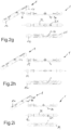
- the process of transferring the tool tip 10 from the disassembled state to the assembled state is illustrated step by step.
- the dental instrument i. e. the head section 30, is located at its determined position, which is defined. In this defined position the dental tool tip 10 and/or the insert region has a determined and unique, i. e. unambiguous, orientation within the tool 1.
- the inner side of the channel forming at least a part of the second receiving section 32 is dimensioned such that the inserted head section can be placed into this region only in one defined manner.
- the whole pre-assembled arrangement of insert region and dental tool tip are shifted, preferably along a longitudinal direction of the tool 1.
- the tool 1 includes a long /slotted hole, which guides the dental instrument, especially a cylindrically shaped section of the dental instrument until the head section reaches its desired final position.
- the dental instrument cannot rotate about an axis extending mainly parallel to the longitudinal direction.
- the dental instrument is hindered to rotate, when the insertion process is finished.
- the head section, especially its distal end, including the insert region abuts at an end of the channel forming the first receiving section 31 such that the movement of the head section is also restricted, at least along one direction extending parallel to the longitudinal direction of the base body in the example of figure 2a .
- the pre-assembled tool tip 10 for example the needle, can reach through an opening or hole, being formed at the end of the channel forming the second receiving section 32. The tool tip 10 passing through this opening or hole is located at least partially in a central region of a tool 1 to transfer the dental tool tip 10 between the disassembled and the assembled state.
- the tool 1 includes a first pushing element 11 and a second pushing element 12.
- the first pushing element 11 is assigned to the first receiving section 31 for removing the tool tip 10 from the insert region and the second pushing element 12 is assigned to the second receiving section 21 for performing the assembling.
- the first pushing element 11 and/or the second pushing element 12 are configured as knob-like element and preferably include an interaction section.
- the interaction section being intended for interacting with a thread or spindle-like mechanism for creating a first pushing movement of the first pushing element 11 and/or a second pushing movement of the second pushing element, when it is rotated or turned.
- a pushed movement T is caused by a rotation of the first pushing element 11 and by the corresponding first pushing movement of the first pushing element 11.
- the first pushing movement and/or the second first pushing movement in the embodiment of figure 2a corresponds to a movement along the longitudinal direction of the main body.
- FIG. 2b shows that the proximal end of the tool tip 10 is in contact with the pin-like front region of the second pushing element 12.
- figure 2b shows that the second pushing movement is not finished in the situation being illustrated in figure 2b .
- the second pushing movement continues and due to the contact of the front region of the second pushing element 12 and the distal end of the dental tool tip 10, the second pushing movement P causes a pushed movement T of the dental tool tip 10, especially along a direction being parallel to the longitudinal direction of the main body.
- the second pushing element 11 and the dental tool tip 10 perform movements along the same direction, corresponding to the direction of the second pushing movement P and the pushed movement T.
- the second pushing movement P is finished and as being illustrated, the tool tip 10 is attached to the head section 30 of the dental instrument.
- the tool tip 10 has been transferred from the disassembled state via the pre-assembled state to the assembled state, as illustrated in figure 2c .
- the front region of the second pushing element 12 is dimensioned such that it is greater than the diameter of the proximal end of the dental tool tip 10 and/or a cross section of the insert region at the back side.
- the second pushing element 12 pushes the tool tip 10 such that it is not located in its proper position.
- the second pushing element 12 is configured such that the second pushing movement is automatically stopped when the second pushing element 12 is in its finished state.
- the threads are dimensioned and configured such that there is no further rotation possible, when the front-end region of the second pushing element 12 arrives at the insert region of the head section 30 of the dental instrument.
- the threads are dimensioned and configured such that there is no further rotation possible, when the front-end region of the second pushing element 12 arrives at the insert region of the head section 30 of the dental instrument.
- FIG 2g it is shown that the second pushing element 12 is unscrewed from the final position, in which the assembled state is reached.
- the dental instrument especially the head section 30 having the assembled tool tip 10 from the tool 1, i. e. remove the dental instrument including the dental tool tip 10 from the second receiving section 32. This is shown in figure 2d .
- FIG. 2e) to 2i removing the dental tool tip 10 is illustrated.
- the figures 2e) to 2i show the transfer of the dental tool tip 10 from the assembled state to the disassembled state.
- the head section 30 having the assembled dental tool tip 10 is inserted into the first receiving section 31.
- the first receiving section 31 and the second receiving section 32 are mainly formed similar to each other and are respectively mainly form a channel for inserting the head section 30, especially for locating the head section at least partially, preferably partially, inside these channel-like first receiving sections 31 in a predetermined and defined position.
- the first receiving section 31 of the embodiment in the figures 1 and 2 a) to e) includes the reduced cross section, into which the head section 30 is forwarded or shifted for fixing the head section 30 to hinder a rotation about a rotational axis extending parallel to the longitudinal direction. Further, the head section 30 is inserted into the first receiving section 31 by a combination of a pushed movement, as well as a pivoting movement, which cause the dental tool tip 10 to be aligned along a direction following the channel inside the first receiving section 31 31, especially extending along a direction being parallel to the longitudinal direction of the main body. In figure 2f ), the first receiving section 31 is filled by the head section 30 having the assembled tool tip 10.
- the first pushing element 11 is moved along the pushing direction P, when it performs the first pushing movement.
- the first pushing movement is caused by rotating the first pushing element 11 and due to the threaded interaction section, the rotating first pushing element 11 is shifted along the longitudinal direction for performing the first pushing movement along the pushing direction P.
- the front region of the first pushing elements 11 contacts the proximal end of the tool tip 10.
- the first pushing element 11 and the second pushing element 12 distinguishes from each other with respect to the shape of their front ends/regions.
- the first pushing element 11 has a front region, having a diameter being smaller than the diameter of the proximal end of the dental tool tip 10, especially of the insert region at its back side.
- the back side of the insert region is defined as side being opposite to the front side facing the teeth when the dental instrument is in operation.
- the front-end region could also have a diameter, which is equal to the diameter of the proximal end of the dental tool tip 1.
- the diameter of the front-end region of the second pushing element 12 is larger than the diameter of the proximal end of the dental tool tip 10 or the insert region.
- the first pushing movement pushes the dental tool tip 10 out of the insert region.
- the tool 1 includes a box-like catching area 20, which is configured for receiving the tool tip 10 being removed from the insert region of the head section 30 of the dental instrument.
- the catching area 20 of the tool 1, being illustrated in the figures 1 and 2 is also used to check the wear status of the dental tool tip 10. For this reason, the tool tip 10 being arranged in the inserted state inside the first receiving section 31 and/or the second receiving section 31 extends into the area of the catching area 20.
- Second receiving section 32 and first receiving section 31 share a center section such that the tool tip 10 extends into this area, when it is inserted in either the first receiving section 31 or the second receiving section 32.
- a reference mark 40 By introducing a reference mark 40, it is possible to see whether the attached tool tip 10 reaches to this reference mark 40. In case of a tool tip 10, which does not extend to this reference mark 40, the wear status should hinder the operator from using the tool tip 10 again.
- the catching area 20 provides a visual access and/or as an access for the operator to remove the disassembled tool tip.
- FIG 3 a tool 1 according to a second exemplary embodiment of the present invention is illustrated. Contrary to the shape of the cylindrical base body of the figures 1 and 2 , the shape of the base body is disc-like. Especially, the tool of figure 3 is formed by two, mainly half disc-like, elements, which can be rotated to each other.
- the figure 3 also includes a first receiving section 31 or a second receiving section 32 for placing the dental instrument, especially the head section of the dental instrument inside the first receiving section 31 and/or second receiving section 32.
- a groove 5 is provided at the inner side of the first receiving section 31. In the inserted state, the dental instrument or head section 30 is pressed into the groove 5.
- the tool tip 10 is, for example partially, pressed into this groove 5.
- Figure 3 illustrates a situation, in which the head section 30 is inserted into a first receiving section 31.
- a first receiving section 31 which has a shape, which not only matches the insert region, especially the distal end of the head section 30, but also further parts of the head section, i. e. parts of the instrumental device.
- the first receiving section 31 is mainly formed such that the whole or at least 80% of the head section 30, being screwable to the handpiece, can be arranged and fixed to the first receiving section 30 such that the first receiving section 31 surrounds the head section 30 at least at two sides.
- the arrangement of the tool tip 10, as well as the insert region can also be defined and supported by the very individualized shape of the first receiving section 31, which is configured to receive and to fix the head section 30.
- the figures 3a) to 3c ) show the transfer of the tool tip 10 from the assembled state to the disassemble state.
- a rotation of the first pushing element 12 causes the first pushing element 12 to push the dental tool tip 10 to perform the pushed movement T, which transfers the dental tool 11 tip from the assembled state to the disassembled state.
- the disc-like shape allows to incorporate further functionalities into this tool 1 and in addition also allows to create or to apply huge forces during the rotation movement due to the increased leverage/torque.
- the second receiving section 32 includes an additional section being configured to receive the head section, having a dental tool tip 10 in a pre-assembled state.
- the second receiving section 32 includes an additional free space in the section located at the proximal open end of the insert region, i. e. at its back side, when the head section 30 is inserted into the second receiving section 32.
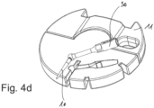
- the embodiment of the figures 3 and 4a ) to d) includes additional functionalities.
- the disc-like base body has a section being shaped as a claw-like section, especially a claw-like section forming a part of an open-end spanner.
- the shapes and sizes of this open-end spanner or claw-like section are adapted to the bottom of a powder chamber such that the tool 1 can also be used to remove a bottom section or bottom plate 52 of a powder chamber 50, in particular by performing a screwing mechanism, and for example to insert powder materials and/or to modify the interior of the powder chamber 50.
- Figures 5a to 5c show how to reassemble or remove the bottom plate 52 from the powder chamber 50.
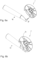
- the figures 6a to 6d show another functionality of the tool 10 being illustrated in the figures 3 , 4 and 5 .
- the disc-like tool includes a recess 33, the recess 33 being configured such that a further dental tool tip from a different dental instrument 41 can be located inside this recess 33.
- the recess 33 is configured such that the recess 33 can be pulled over the further dental tool tip.
- the further dental tool tip is a nozzle element 38 being attached to a handpiece of a powder jet device.
- a powder jet device provides a powder gas mixture, as well as a liquid which exits through the nozzle element being illustrated here.
- the nozzle element especially is attached to the handpiece by a T-slot 39.
Landscapes
- Health & Medical Sciences (AREA)
- Oral & Maxillofacial Surgery (AREA)
- Dentistry (AREA)
- Epidemiology (AREA)
- Life Sciences & Earth Sciences (AREA)
- Animal Behavior & Ethology (AREA)
- General Health & Medical Sciences (AREA)
- Public Health (AREA)
- Veterinary Medicine (AREA)
- Dental Tools And Instruments Or Auxiliary Dental Instruments (AREA)
Priority Applications (5)
| Application Number | Priority Date | Filing Date | Title |
|---|---|---|---|
| EP22203107.2A EP4356872A1 (fr) | 2022-10-21 | 2022-10-21 | Outil pour transférer une pointe d'outil dentaire entre un état assemblé et un état démonté et procédé pour retirer une pointe d'outil dentaire d'un instrument dentaire |
| EP22207883.4A EP4356866A1 (fr) | 2022-10-21 | 2022-11-16 | Support de pointe, pointe d'outil et outil médical |
| CN202310592085.6A CN117917230A (zh) | 2022-10-21 | 2023-05-24 | 梢部保持器、工具梢部和医疗工具 |
| PCT/EP2023/078711 WO2024083763A1 (fr) | 2022-10-21 | 2023-10-16 | Support d'embout, embout d'instrument et instrument médical |
| PCT/EP2023/079342 WO2024084068A1 (fr) | 2022-10-21 | 2023-10-20 | Outil pour transférer une pointe d'outil dentaire entre un état assemblé et démonté et procédé pour retirer une pointe d'outil dentaire d'un instrument dentaire |
Applications Claiming Priority (1)
| Application Number | Priority Date | Filing Date | Title |
|---|---|---|---|
| EP22203107.2A EP4356872A1 (fr) | 2022-10-21 | 2022-10-21 | Outil pour transférer une pointe d'outil dentaire entre un état assemblé et un état démonté et procédé pour retirer une pointe d'outil dentaire d'un instrument dentaire |
Publications (1)
| Publication Number | Publication Date |
|---|---|
| EP4356872A1 true EP4356872A1 (fr) | 2024-04-24 |
Family
ID=83994984
Family Applications (2)
| Application Number | Title | Priority Date | Filing Date |
|---|---|---|---|
| EP22203107.2A Pending EP4356872A1 (fr) | 2022-10-21 | 2022-10-21 | Outil pour transférer une pointe d'outil dentaire entre un état assemblé et un état démonté et procédé pour retirer une pointe d'outil dentaire d'un instrument dentaire |
| EP22207883.4A Pending EP4356866A1 (fr) | 2022-10-21 | 2022-11-16 | Support de pointe, pointe d'outil et outil médical |
Family Applications After (1)
| Application Number | Title | Priority Date | Filing Date |
|---|---|---|---|
| EP22207883.4A Pending EP4356866A1 (fr) | 2022-10-21 | 2022-11-16 | Support de pointe, pointe d'outil et outil médical |
Country Status (3)
| Country | Link |
|---|---|
| EP (2) | EP4356872A1 (fr) |
| CN (1) | CN117917230A (fr) |
| WO (1) | WO2024084068A1 (fr) |
Citations (2)
| Publication number | Priority date | Publication date | Assignee | Title |
|---|---|---|---|---|
| US20110166555A1 (en) * | 2009-09-30 | 2011-07-07 | Jianbo Zhou | Carrier for an insertable medical device, insertion tools, methods of use, and kits |
| EP2662312A1 (fr) * | 2012-05-08 | 2013-11-13 | Dentsply IH AB | Emballage pour forets, procédé et agencement associé |
Family Cites Families (3)
| Publication number | Priority date | Publication date | Assignee | Title |
|---|---|---|---|---|
| EP3858286B1 (fr) * | 2020-01-28 | 2023-08-02 | Ferton Holding S.A. | Outil pour un traitement médical |
| WO2021152049A1 (fr) * | 2020-01-28 | 2021-08-05 | Ferton Holding S.A. | Outil pour un traitement médical, de préférence un traitement dentaire, et méthode de fonctionnement d'un tel outil |
| EP3858285B1 (fr) * | 2020-01-28 | 2023-06-07 | Ferton Holding S.A. | Outil pour un traitement médical |
-
2022
- 2022-10-21 EP EP22203107.2A patent/EP4356872A1/fr active Pending
- 2022-11-16 EP EP22207883.4A patent/EP4356866A1/fr active Pending
-
2023
- 2023-05-24 CN CN202310592085.6A patent/CN117917230A/zh active Pending
- 2023-10-20 WO PCT/EP2023/079342 patent/WO2024084068A1/fr unknown
Patent Citations (2)
| Publication number | Priority date | Publication date | Assignee | Title |
|---|---|---|---|---|
| US20110166555A1 (en) * | 2009-09-30 | 2011-07-07 | Jianbo Zhou | Carrier for an insertable medical device, insertion tools, methods of use, and kits |
| EP2662312A1 (fr) * | 2012-05-08 | 2013-11-13 | Dentsply IH AB | Emballage pour forets, procédé et agencement associé |
Also Published As
| Publication number | Publication date |
|---|---|
| EP4356866A1 (fr) | 2024-04-24 |
| CN117917230A (zh) | 2024-04-23 |
| WO2024084068A1 (fr) | 2024-04-25 |
Similar Documents
| Publication | Publication Date | Title |
|---|---|---|
| JP5996132B2 (ja) | ワイヤドライバ | |
| JP7004762B2 (ja) | 長骨に髄内釘を固定する位置決め装置 | |
| US8414594B2 (en) | Magazine for receiving at least one bone screw and bone plate having such a magazine | |
| KR101433683B1 (ko) | 구강관통 플레이트 유지 캐뉼라 | |
| US9089378B2 (en) | Kirschner wire clamp | |
| JP2006508755A (ja) | 外科用開創器システム | |
| US9763675B2 (en) | Angled instrument assembly | |
| DK1721583T3 (en) | Implant for insertion between vertebrae and surgical instrument for handling the implant | |
| JP4969921B2 (ja) | 柔軟性クランプを有する歯科用又は医科用ハンドピース | |
| KR101832511B1 (ko) | 스크류 전달 시스템 | |
| EP1648320A2 (fr) | Dispositif de fixation spinale de chargement superieur et instrument pour charger et pour manipuler ce dispositif | |
| EP4356872A1 (fr) | Outil pour transférer une pointe d'outil dentaire entre un état assemblé et un état démonté et procédé pour retirer une pointe d'outil dentaire d'un instrument dentaire | |
| JPS6173647A (ja) | 歯科用ハンドピース | |
| US6174162B1 (en) | Instrument for adjusting orthodontic expander | |
| JP2005521482A (ja) | 屈曲的に変形可能な工具用の工具ホルダ | |
| JP2016530938A (ja) | インプラントに対して外科用ロッドを操作、位置決め及び固定するための外科用器具 | |
| US2441846A (en) | Tool for handling open-ended retaining rings | |
| JP4524448B2 (ja) | 医療用回転切削器具のアタッチメント | |
| KR100511883B1 (ko) | 한방용 침 | |
| KR200428275Y1 (ko) | 핸드피스용 브레이킹 겸용 푸싱장치 | |
| RU2007136C1 (ru) | Хирургическая дрель | |
| JP2001212151A (ja) | 骨手術用穿孔ストッパ及び骨手術用穿孔具 | |
| EP3886742B1 (fr) | Outil chirurgical pour positionner un dispositif chirurgical, dispositif chirurgical et kit | |
| EP1232731B1 (fr) | Pièce à main dentaire avec moyen servant à libérer la fraise perfectionné | |
| JP2001224600A5 (fr) |
Legal Events
| Date | Code | Title | Description |
|---|---|---|---|
| PUAI | Public reference made under article 153(3) epc to a published international application that has entered the european phase |
Free format text: ORIGINAL CODE: 0009012 |
|
| STAA | Information on the status of an ep patent application or granted ep patent |
Free format text: STATUS: THE APPLICATION HAS BEEN PUBLISHED |
|
| AK | Designated contracting states |
Kind code of ref document: A1 Designated state(s): AL AT BE BG CH CY CZ DE DK EE ES FI FR GB GR HR HU IE IS IT LI LT LU LV MC ME MK MT NL NO PL PT RO RS SE SI SK SM TR |