EP4355512B1 - Verfahren zum giessen von gussteilen - Google Patents
Verfahren zum giessen von gussteilen Download PDFInfo
- Publication number
- EP4355512B1 EP4355512B1 EP22734570.9A EP22734570A EP4355512B1 EP 4355512 B1 EP4355512 B1 EP 4355512B1 EP 22734570 A EP22734570 A EP 22734570A EP 4355512 B1 EP4355512 B1 EP 4355512B1
- Authority
- EP
- European Patent Office
- Prior art keywords
- filling
- casting
- casting mold
- filling material
- mold
- Prior art date
- Legal status (The legal status is an assumption and is not a legal conclusion. Google has not performed a legal analysis and makes no representation as to the accuracy of the status listed.)
- Active
Links
Images

Classifications
-
- B—PERFORMING OPERATIONS; TRANSPORTING
- B22—CASTING; POWDER METALLURGY
- B22C—FOUNDRY MOULDING
- B22C9/00—Moulds or cores; Moulding processes
- B22C9/02—Sand moulds or like moulds for shaped castings
-
- B—PERFORMING OPERATIONS; TRANSPORTING
- B22—CASTING; POWDER METALLURGY
- B22C—FOUNDRY MOULDING
- B22C9/00—Moulds or cores; Moulding processes
- B22C9/02—Sand moulds or like moulds for shaped castings
- B22C9/04—Use of lost patterns
- B22C9/046—Use of patterns which are eliminated by the liquid metal in the mould
-
- B—PERFORMING OPERATIONS; TRANSPORTING
- B22—CASTING; POWDER METALLURGY
- B22C—FOUNDRY MOULDING
- B22C9/00—Moulds or cores; Moulding processes
- B22C9/10—Cores; Manufacture or installation of cores
Definitions
- the invention relates to a method for casting castings, in which a molten metal is poured into a casting mold enclosing a cavity representing the casting to be produced, wherein the casting mold, as a lost mold, consists of one or more casting mold parts or cores formed from a molding material consisting of core sand, a binder, and optionally one or more additives for adjusting certain properties of the molding material.
- the casting mold provided in each case is housed in a housing such that a filling space is formed between at least one inner surface section of the housing and an associated outer surface section of the casting mold.
- the filling space is then filled with free-flowing filling material, wherein the filling material filled into the filling space has such a low bulk density that the filling material packing formed from the filling material there after the filling of the filling space can be flowed through by a gas flow.
- the molten metal is poured into the mold thus enclosed, whereby the mold begins to radiate heat as the molten metal is poured in, which is the result of the heat input caused by the hot molten metal, and whereby as a result of the heat input caused by the molten metal, the binder of the molding material begins to evaporate and burn, so that it loses its effectiveness and the mold disintegrates into fragments.
- quartz sands mixed with bentonites, lustrous carbon formers and Water is used as the molding material for the casting parts that form the outer edge of the mold.
- the casting cores which represent the internal cavities and channels of the casting, are usually formed from commercially available core sands mixed with an organic or inorganic binder, e.g., a synthetic resin or water glass.
- the basic principle in the production of casting molds formed from molding materials of the type mentioned above is that after molding, the binder is cured by a suitable thermal or chemical treatment so that the grains of the core sand stick together and the dimensional stability of the respective molded part or core is guaranteed over a sufficient period of time.
- the internal pressure exerted on the mold after the molten metal has been poured out can be very high.
- either thick-walled, large-volume molds or support structures that support the mold on its exterior must be used.
- One possible support structure is a housing that is placed over the casting mold.
- the housing is usually designed like a jacket that surrounds the casting mold on its peripheral sides, but has a sufficiently large opening on its top to allow the melt to be poured into the casting mold.
- the housing is dimensioned such that, after placement, a filling space remains between the inner surfaces of the housing and the outer surfaces of the casting mold, at least in the sections that are crucial for supporting the casting mold.
- This filling space is filled with a free-flowing filling material, so that a Extensive support of the respective surface section on the enclosure is ensured.
- fine-grained, free-flowing filling materials such as sand or steel grit, which have a high bulk density, are generally used. After filling, the filling material is further compacted.
- the aim here is to create a filling mass that is as compact as possible, which, like an incompressible monolith, ensures the direct transfer of the supporting forces from the enclosure to the casting mold.
- the molten metal is poured into the mold at high temperature, so that the mold parts and cores that make up the mold are also heated up considerably. As a result, the mold begins to radiate heat. If the temperature of the mold exceeds a certain minimum temperature, the binder in the molding material begins to evaporate and burn, releasing further heat. The binder thus loses its effectiveness. Due to this decomposition of the binder, the bond between the grains of the molding material from which the mold parts and cores are made is lost, and the mold, or rather its parts and cores made of molding material, disintegrates into individual fragments.
- the WO 2016/016035 A1 It has been proposed to use a preheated filling material to fill the filling space between the casting mould and the housing, whereby the filling temperature of the filling material is so high that, starting from the filling temperature, the temperature of the filling material rises above a limit temperature by process heat, which is generated by the heat radiated from the casting mould and by the heat released during the combustion of the binder, at which the The evaporating binder that comes into contact with the filling material is ignited and its combustion begins.
- the filling material is used as a heat accumulator, which is temperature-controlled and designed in such a way that the decomposition of the binder in the molding material from which the mold parts and cores are made progresses largely due to the effects of temperature during the dwell time in the housing.
- 500 °C has been considered a suitable lower limit for the filling temperature range.
- the task arose to improve the known process in such a way that the rapid and energy-efficient decomposition of the casting mold is achieved with reduced effort.
- the invention has solved this problem by the method specified in claim 1.
- the filling material has a filling material temperature when being filled into the filling chamber that does not have a negative effect on the properties of the molding material before casting.
- the filling material temperature that the filling material has when being filled into the filling chamber is limited to less than 100 °C. What is essential for the invention here is that no targeted heating of the filling material to a specific target temperature is carried out. Rather, the filling material is advantageously filled into the filling chamber at the temperature that it currently has, i.e. the temperature that it has assumed as a result of, for example, the ambient temperature at the location where the filling material has been stored or of process heat that occurs, for example, in a recycling process or the like.
- the filling material temperature provided according to the invention is preferably at least equal to the room temperature that prevails in the vicinity of the storage location of the filling material or the respective Pouring device, or with which the filling material reaches the pouring device, into whose filling chamber it is filled, without targeted, active heat supply.
- the filling material temperatures with which the filling material is filled into the filling chamber are typically in the range of 10 °C to 45 °C, in particular 18 - 45 °C, with typical room temperatures being in the range of 10 - 25 °C, in particular 18 - 25 °C, depending on the season.
- the method according to the invention can be implemented with significantly simplified plant technology compared to the prior art.
- the filling material can be actively or passively cooled if necessary.
- the invention thus allows for a temporal decoupling of the process of filling the filling chamber with the filling material from the filling of the casting mold with the respective molten metal. Since it is no longer important that the filling material in the filling chamber has a certain high temperature, such as the at least 500 °C considered practical in the prior art, Because the temperature is not too high but at a temperature that does not adversely affect the mold material, the filling chamber can be filled long before the molten metal is poured out. This temporal decoupling of the filling process from the casting process makes the process significantly more robust and stable. The result is optimized operational reliability while simplifying the practical implementation of the process.
- the cooling of the casting in the process according to the invention is faster than in the prior art described above, since the cold filler material, i.e., at a temperature of less than 100 °C, in particular at most 45 °C, preferably at room temperature, acts as a heat sink, removing heat from the mold until the temperature is equalized.
- the resulting faster solidification of the casting leads to increased dimensional stability of the workpiece.
- the process according to the invention also proves to be more energy-efficient.
- the cores have also disintegrated into at least large fragments, which form channels or cavities inside the casting, so that the core sand and the moulding material fragments of these cores either trickle out of the casting automatically while still in the casing or in a known manner. way, for example by mechanical methods such as shaking or by flushing with a suitable fluid.
- the core sand fragments can be crushed, for example, in a conventional grinder.
- the reclaimed sand obtained after processing can be mixed with new sand in a conventional manner.
- the method according to the invention is based on the idea of not only stabilizing the casting mold with the filling material, but also accelerating the removal of heat in order to produce high-precision castings in a technologically and economically effective manner.
- the filling material filled according to the invention into the filling space formed between the casting and the housing is free-flowing, so that it completely fills the filling space even if undercuts, cavities and the like are present in the area of the outer surfaces of the casting mold.
- the filling material used according to the invention has, in the manner known from the prior art, a bulk density which is so low that it can still be permeated by a gas flow even after the filling chamber has been filled and, if necessary, the filling material filled into the filling chamber has been compacted.
- the invention therefore expressly does not produce a highly compacted packing in the filling chamber, which, although it ensures optimal support of the casting mold, is largely impermeable to gas. Rather, the filling material used according to the invention must be selected so that it is permeable to a gas flow. which occurs, for example, as a result of thermal convection. This occurs when the casting mold is heated by the molten metal poured into it and the evaporating binder components of the mold material of the casting mold parts and cores begin to evaporate and burn, releasing heat.
- binder components that become vaporous and combustible when heat is applied. This does not exclude the possibility that other binder components remain in the mold in solid or other forms, for example, as cracking products, and are also optimally decomposed by heat.
- the ability of the filling material filled into the filling chamber to be permeated by a gas stream according to the invention and the large-volume design of the filling frame surrounding the filling chamber adapted for this purpose not only create the possibility that the binder evaporating from the casting mold burns in the area of the filling material itself and thereby heats the filling material, but also allow the supply of oxygen, which supports the combustion of the binder.
- Casting molds whose molded parts and cores consist of molding material bound by an organic binder are particularly suitable for the process according to the invention.
- Commercially available solvent-based binders or binders whose effect is triggered by a chemical reaction are suitable for this purpose.
- Such binder systems are currently used in the so-called "cold box process.”
- the filling material temperature which the filling material has when filling into the filling chamber, is, as already mentioned, selected according to the invention in such a way that even if the filling material is filled into the filling chamber before casting, no negative effects on the moulding material and in particular the binder occur, by which holds together the grains of the molding material from which the parts and cores of the mold are formed.
- the effects achieved by the invention occur even when the filling material temperature during filling of the filling chamber is equal to the ambient temperature, i.e., equal to the temperature prevailing at the location where the filling material is stored before it is filled into the filling chamber.
- the ambient temperature i.e., equal to the temperature prevailing at the location where the filling material is stored before it is filled into the filling chamber.
- no temperature control of the filling material is performed, so that, unlike the prior art, no costs are incurred for temperature control and, if necessary, thermally insulated storage of the filling material.
- Typical filling material temperatures provided according to the invention are, as already mentioned, in the range of up to 45 °C.
- the mold parts and cores formed from molding material disintegrate into loose fragments that can either be disposed of and recycled after the housing is removed, or, more advantageously, can be removed from the housing during the residence time between the pouring of the molten metal and the removal of the housing.
- the mold can be placed on a sieve bottom, and the mold fragments trickling through the sieve bottom can be collected.
- the openings in the sieve bottom are designed so that the mold fragments and the filling material trickle through the sieve bottom together, are collected, processed, and separated from one another after processing. This has the advantage that no loose filling material remains in the housing when the housing is removed.
- the mold housing can be made of sufficiently rigid sheet metal surrounding the mold with a sufficient clearance to form the filling chamber, and without any special thermal insulation requirements.
- a perforated support plate acting as a sieve plate can be provided, on which the mold is placed.
- An exhaust opening can be provided to enable controlled discharge of the exhaust gases generated in the filling chamber.
- the filling material filled into the filling chamber can also be compacted in a conventional manner to create a prestress between the casting mold and the housing, ensuring secure, precisely positioned cohesion of the casting mold even when the casting mold is designed as a core package composed of a plurality of molded parts and cores.
- the permeability of a gas stream is ensured even with such a compacted filling material.
- Channels specifically introduced into the casting mold can also be used to accelerate the cooling of certain zones on or in the casting or to avoid such accelerated cooling in order to achieve certain properties of the casting in the respective zone.
- Granules or other granular bulk materials have proven to be suitable filling materials.
- Bulk materials with bulk densities of up to 4 kg/dm 3 , particularly less than 1 kg/dm 3 or even less than 0.5 kg/dm 3 are particularly suitable for the purposes of the invention.
- the diameter of the spheres is preferably in the range of 1.5 - 100 mm, especially 1.5 - 40 mm.
- any thermally resilient bulk material that meets the above-mentioned requirements and is sufficiently temperature-resistant is suitable as a filling material.
- Non-metallic bulk materials such as granules made of ceramic materials, are particularly suitable for this purpose. These can be irregularly shaped, spherical, or have cavities to ensure good gas permeation of the filling material while simultaneously having low heat storage properties.
- the filling material can also consist of ring-shaped or polygonal elements that only touch each other at points when in contact, leaving sufficient space between them to ensure good airflow.
- the filling material can consist of ceramic or refractory materials.
- the casting exposed after demoulding according to the invention can, in a manner known per se, undergo a heat treatment after the disintegration of the casting mould, in which it is cooled in a manner known per se in a controlled manner according to a specific cooling curve in order to produce a specific state of the casting.
- casting molds can be accommodated together in one housing at the same time and these casting molds can be filled with molten metal in parallel or in close succession.
- the method according to the invention is suitable for any type of metallic casting material that generates a sufficiently high process heat during processing.
- the method according to the invention is particularly suitable for the production of cast iron castings because, due to the high temperature of the cast iron melt, the temperatures intended for the combustion of the binder can be achieved particularly reliably.
- process GJL, GJS and GJV cast iron materials as well as cast steel in the inventive manner.
- the method according to the invention is particularly suitable for the casting production of cylinder crankcases and cylinder heads for internal combustion engines. Especially when the components in question are intended for commercial vehicles, they and the casting mold required for their production have a comparatively large volume, in which case the advantages of the method according to the invention are particularly evident.
- the casting cores and molds are manufactured in a conventional manner using the cold-box process from a conventional molding material, which can be a mixture of commercially available core sand, an equally commercially available organic binder, and optionally added additives, which, for example, serve to improve the wetting of the core sand grains by the binder.
- a conventional molding material which can be a mixture of commercially available core sand, an equally commercially available organic binder, and optionally added additives, which, for example, serve to improve the wetting of the core sand grains by the binder.
- the resulting casting cores and molds are gassed with a reaction gas to bond the organic binder through a chemical reaction. to harden and thereby give the casting cores and molded parts the necessary dimensional rigidity.
- casting mold 1 is assembled from the conventionally prepared casting mold parts and cores in a similarly known manner to form a so-called "core package" of casting mold 1.
- casting mold 1 may comprise components made of steel or other indestructible materials. These include, for example, chills and the like, which are arranged in casting mold 1 to achieve directional solidification of the casting G through accelerated solidification of the melt that comes into contact with the chill.
- the casting mold 1 is intended for the casting production of a casting G, which in the present example is a cylinder crankcase for a commercial vehicle combustion engine.
- new filling material is provided, for example granular, in particular spherical, ceramic granules with a grain size of 1.5 - 25 mm determined in a conventional manner by sieving, which has room temperature (typically 18 - 25 °C), whereby filling material temperatures of up to 45 °C are practical here.
- the Figures 1 - 8 The device T shown in various phases of the method according to the invention has a sieve plate 2 on which the casting mold 1 prepared for pouring a cast iron melt is placed.
- the casting mold 1 defines a mold cavity 3 from the surroundings U, into which the molten iron is poured to form the casting G.
- the molten iron flows into the mold cavity 3 via a gating system, which is not shown here for the sake of clarity.
- the sieve plate 2 is supported by its edge on a circumferential edge shoulder 4 of a collecting container 5.
- a sealing element 6 is incorporated into the circumferential contact surface of the edge shoulder 4.
- the housing 7 is designed like a hood and encloses the casting mold 1 on its outer circumferential surfaces 8.
- the circumference of the space delimited by the housing 7 is oversized compared to the circumference of the casting mold 1, so that after the housing 7 is placed on the sieve plate 2, a filling space 10 is formed between the outer circumferential surface of the casting mold 1 and the inner surface 9 of the housing 7.
- the housing 7 sits on the sealing element 6, so that a tight closure of the filling space 10 with respect to the environment U is ensured.
- the housing consists of a sheet metal material, the thermally insulating properties of which do not require any special requirements.
- the sheet metal material is designed in a conventional manner to ensure the necessary dimensional stability of the housing 7.
- the housing 7 defines a large opening 11 through which the casting mold 1 can be filled with molten iron and the filling chamber 10 with filling material F ( Fig. 2 ).
- a storage container V is positioned above the opening 11, from which the untempered filling material F is then allowed to trickle into the filling chamber 10 via a distribution system 12 ( Fig. 3 ).
- the filling material package filled into the filling chamber 10 can be compacted if necessary.
- a lid 13 is then placed over the opening 11, which also has an opening 14 through which the molten iron can be filled into the casting mold 1 ( Fig. 4 ).
- the iron casting melt is then poured into the casting mould 1 ( Fig. 5 ).
- oxygen-containing ambient air can enter the filling chamber 10 via a gas inlet 15 formed in the lower edge area of the housing 7.
- ambient air which enters the collecting container 5 via an inlet 16, is sucked through the sieve bottom 2 into the filling chamber 10 ( Fig. 6 ).
- the solvent contained in the binder evaporates.
- the vaporous solvent escaping from the casting mold 1 burns due to the heat radiated by the casting G as it emerges from the casting mold 1.
- the combustion of the binder components and other potential pollutants escaping from the casting mold 1 continues without further energy input until no more binder evaporates from the casting mold 1. Any solvents still escaping from the casting mold 1 vaporous substances are oxidized or otherwise rendered harmless by the high temperature prevailing in the filling chamber 10.
- the filling material packing in the filling chamber 10 supports the casting mold 1 at its peripheral surfaces 8, thus preventing the iron casting melt from breaking through from the casting mold 1.
- the mold parts and cores of the casting mold 1 disintegrate into fragments B or individual grains of sand, which fall through the sieve bottom 2 into the collecting container 5 and are collected there.
- the sieve bottom 2 can be opened in such a way that filling material F also reaches the collecting container 5 ( Fig. 7 ).
- the progression of the destruction of the casting mold 1 and the solidification process of the cast iron melt poured into the casting mold 1 are adapted to each other in such a way that the casting G has solidified sufficiently when the disintegration of the casting mold 1 begins.
- the low temperature of the filling material F contributes to the rapid cooling of the casting mold 1 and, with it, the casting G. In this way, a particularly good dimensional accuracy of the casting G is achieved.
- the collecting container 5 with the molding material-filling material mixture contained therein is separated from the sieve bottom 2 and the housing 7 is also removed from the sieve bottom 2 ( Fig. 8 ).
- the largely desanded casting G is now freely accessible and can be cooled in a tunnel-like space 17 provided for this purpose ( Fig. 9 ).
- casting G Due to the process, casting G has a high temperature upon removal, as the austenite transformation is not yet complete, and rapid cooling would lead to residual stresses and thus cracks. For this reason, casting G is slowly cooled in a cooling tunnel 17 according to the annealing curves during stress relief annealing.
- the supplied cooling air is dimensioned to achieve the product-specific cooling profile.
- the still hot mixture of filling material F, core sand and fragments B collected in the collecting container 5 is WO 2016/016035 A1 prepared in the manner described.
- the core sand obtained through processing is used to produce new casting mold parts and cores.
- the filling material F obtained by the processing is cooled to room temperature in air without additional energy supply and stored in the storage container V for refilling of the filling chamber 10.
- the invention thus provides a method for casting castings (G), in which a metal melt is poured into a casting mold 1, wherein the casting mold 1, as a lost mold, consists of one or more casting mold parts or cores formed from a molding material consisting of a core sand, a binder and optionally one or more additives for setting certain
- the filling material F has a filling material temperature of less than 100 °C when it is filled into the filling chamber 10, the rapid and energy-efficient decomposition of the casting mold 1 can be achieved with reduced effort.
Landscapes
- Engineering & Computer Science (AREA)
- Mechanical Engineering (AREA)
- Mold Materials And Core Materials (AREA)
- Molds, Cores, And Manufacturing Methods Thereof (AREA)
Description
- Die Erfindung betrifft ein Verfahren zum Gießen von Gussteilen, bei dem eine Metallschmelze in eine Gießform abgegossen wird, die einen das zu erzeugende Gussteil abbildenden Hohlraum umschließt, wobei die Gießform als verlorene Form aus einem oder mehreren Gießformteilen oder -kernen besteht, die aus einem Formstoff geformt sind, der aus einem Kernsand, einem Binder und optional einem oder mehreren Zusätzen zur Einstellung bestimmter Eigenschaften des Formstoffs besteht. Im Zuge dieses Verfahrens wird die jeweils bereitgestellte Gießform in ein Gehäuse derart eingehaust, dass ein Füllraum zwischen mindestens einem Innenflächenabschnitt des Gehäuses und einem zugeordneten Außenflächenabschnitt der Gießform gebildet ist. Dann wird der Füllraum mit rieselfähigen Füllgut befüllt, wobei das in den Füllraum gefüllte Füllgut eine so geringe Schüttdichte besitzt, dass die nach dem Befüllen des Füllraums dort aus dem Füllgut gebildete Füllgutpackung von einer Gasströmung durchströmbar ist. In die so eingehauste Gießform wird die Metallschmelze abgegossen, wobei die Gießform einhergehend mit dem Eingießen der Metallschmelze beginnt, Wärme abzustrahlen, die Folge des durch die heiße Metallschmelze bewirkten Wärmeeintrags ist, und wobei in Folge des durch die Metallschmelze bewirkten Wärmeeintrags der Binder des Formstoffs zu verdampfen und zu verbrennen beginnt, so dass er seine Wirkung verliert und die Gießform in Bruchstücke zerfällt.
- Die Grundzüge des so ablaufenden Verfahrens und die für die praktische Umsetzung vorteilhaften Ausgestaltungen dieses Verfahrens sind in der
WO 2016/016035 A1 beschrieben. - Wie dort erläutert, werden im Bereich des Eisengusses üblicherweise Quarzsande, gemischt mit Bentoniten, Glanzkohlenstoffbildnern und Wasser als Formstoff für die den äußeren Abschluss der Gießform bildenden Gießformteile eingesetzt. Die die innenliegenden Höhlungen und Kanäle des Gussteils abbildenden Gießkerne werden dagegen üblicherweise aus handelsüblichen Kernsanden geformt, die mit einem organischen oder anorganischen Binder, z. B. mit einem Kunstharz oder Wasserglas, vermischt sind.
- Unabhängig von der Art der Kernsande und Binder besteht das Grundprinzip bei der Herstellung von aus Formstoffen der voranstehend genannten Art geformten Gießformen darin, dass nach der Formgebung der Binder durch eine geeignete thermische oder chemische Behandlung ausgehärtet wird, so dass die Körner des Kernsands miteinander verkleben und über eine ausreichende Dauer die Formfestigkeit des jeweiligen Formteils oder -kerns gewährleistet ist.
- Gerade beim Gießen großvolumiger Gussteile aus Eisenguss kann der auf der Gießform nach dem Abgießen der Metallschmelze lastende Innendruck sehr hoch sein. Um diesen Druck aufzunehmen und ein Bersten der Gießform sicher zu vermeiden, müssen entweder dickwandige, großvolumige Gießformen oder Stützkonstruktionen eingesetzt werden, die die Gießform an ihrer Außenseite abstützen.
- Eine Möglichkeit einer solchen Stützkonstruktion besteht in einer Einhausung, die über die Gießform gestülpt wird. Die Einhausung ist üblicherweise nach Art eines Mantels ausgebildet, der die Gießform an ihren Umfangsseiten umgibt, jedoch an ihrer Oberseite eine ausreichend große Öffnung aufweist, um das Abgießen der Schmelze in die Gießform zu ermöglichen. Die Einhausung ist dabei so bemessen, dass nach dem Aufsetzen zumindest in den für die Abstützung der Gießform entscheidenden Abschnitten zwischen den Innenflächen der Einhausung und den Außenflächen der Gießform ein Füllraum vorhanden bleibt. Dieser Füllraum wird mit einem rieselfähigen Füllgut gefüllt, so dass eine großflächige Abstützung des jeweiligen Flächenabschnitts an der Einhausung gewährleistet ist. Um hier eine möglichst gleichmäßige Füllung des Füllraums, einen ebenso gleichmäßigen Kontakt der Gießform mit dem Füllmaterial und eine dementsprechend gleichmäßige Abstützung des zerbrechlichen Gießformstoffs zu erzielen, werden als Füllgut in der Regel feinkörnige, rieselfähige Füllmaterialien, wie Sand oder Stahlkies, verwendet, die eine hohe Schüttdichte besitzen. Nach dem Befüllen wird das Füllgut zusätzlich verdichtet. Ziel ist es hier, eine möglichst kompakte Füllmasse zu erzeugen, die nach Art eines inkompressiblen Monolithen die direkte Übertragung der Stützkräfte von der Einhausung auf die Gießform sicherstellt.
- Die Metallschmelze wird mit hoher Temperatur in die Gießform gegossen, so dass auch die Gießformteile und -kerne, aus denen die Gießform zusammengesetzt ist, stark erwärmt werden. In Folge dessen beginnt die Gießform Wärme abzustrahlen. Übersteigt die Temperatur der Gießform eine bestimmte Mindesttemperatur, so beginnt der Binder des Formstoffs zu verdampfen und unter Freisetzung weiterer Wärme zu verbrennen. Der Binder verliert dadurch seine Wirkung. Durch diese Zersetzung des Binders geht die Bindung der Körner des Formstoffs, aus dem die Gießformteile und -kerne der Gießform hergestellt sind, verloren und die Gießform bzw. ihre aus Formstoff bestehenden Teile und Kerne zerfallen in einzelne Bruchstücke.
- Hierauf aufsetzend ist in der
WO 2016/016035 A1 vorgeschlagen worden, ein vorerwärmtes Füllgut zum Befüllen des zwischen Gießform und Einhausung vorhandenen Füllraums zu verwenden, wobei die Einfülltemperatur des Füllguts so hoch ist, dass ausgehend von der Einfülltemperatur durch Prozesswärme, die durch die von der Gießform abgestrahlte Wärme und durch die bei der Verbrennung des Binders freiwerdende Wärme gebildet wird, die Temperatur des Füllguts bis über eine Grenztemperatur ansteigt, bei der der aus der Gießform ausdampfende, mit dem Füllgut in Kontakt kommende Binder zündet und seine Verbrennung einsetzt. Auf diese Weise wird das Füllgut im Sinne eines Wärmespeichers genutzt, der so temperiert und ausgebildet ist, dass die Zersetzung des Binders des Formstoffs, aus dem die Gießformteile und -kerne der Gießform gefertigt sind, schon während der Verweilzeit in der Einhausung durch Temperatureinwirkung weitestgehend fortschreitet. 500 °C sind dabei als geeignete Untergrenze für den Bereich der Einfülltemperaturen angesehen worden. - Ausgehend hiervon hat sich die Aufgabe ergeben, das bekannte Verfahren so zu verbessern, dass bei vermindertem Aufwand die schnelle und energieeffiziente Zersetzung der Gießform erzielt wird.
- Die Erfindung hat diese Aufgabe durch das in Anspruch 1 angegebene Verfahren gelöst.
- Vorteilhafte Ausgestaltungen der Erfindung sind in den abhängigen Ansprüchen angegeben und werden nachfolgend wie der allgemeine Erfindungsgedanke im Einzelnen erläutert.
- Die Erfindung stellt demnach ein Verfahren zum Gießen von Gussteilen zur Verfügung, bei dem in Übereinstimmung mit dem voranstehend erläuterten Stand der Technik eine Metallschmelze in eine Gießform abgegossen wird, die einen das zu erzeugende Gussteil abbildenden Hohlraum umschließt, wobei die Gießform als verlorene Form aus einem oder mehreren Gießformteilen oder -kernen besteht, die aus einem Formstoff geformt sind, der aus einem Kernsand, einem Binder und optional einem oder mehreren Zusätzen zur Einstellung bestimmter Eigenschaften des Formstoffs besteht, umfassend folgende Arbeitsschritte:
- Bereitstellen der Gießform;
- Einhausen der Gießform in ein Gehäuse unter Ausbildung eines Füllraums zwischen mindestens einem Innenflächenabschnitt des Gehäuses und einem zugeordneten Außenflächenabschnitt der Gießform;
- Befüllen des Füllraums mit rieselfähigem Füllgut, wobei das in den Füllraum gefüllte Füllgut eine so geringe Schüttdichte besitzt, dass die nach dem Befüllen des Füllraums dort aus dem Füllgut gebildete Füllgutpackung von einer Gasströmung durchströmbar ist;
und - Abgießen der Metallschmelze in die Gießform,
- wobei die Gießform einhergehend mit dem Eingießen der Metallschmelze beginnt, Wärme abzustrahlen, die Folge des durch die heiße Metallschmelze bewirkten Wärmeeintrags ist,
und - wobei in Folge des durch die Metallschmelze bewirkten Wärmeeintrags der Binder des Formstoffs zu verdampfen und zu verbrennen beginnt, so dass er seine Wirkung verliert und die Gießform in Bruchstücke zerfällt.
- Erfindungsgemäß weist nun das Füllgut beim Einfüllen in den Füllraum eine Füllgut-Temperatur auf, die sich nicht negativ auf die Eigenschaften des Formstoffs vor dem Abgießen auswirkt. Hierzu ist erfindungsgemäß die Füllgut-Temperatur, die das Füllgut beim Einfüllen in den Füllraum aufweist, auf weniger als 100 °C begrenzt. Wesentlich für die Erfindung ist hier, dass keine gezielte Erwärmung des Füllguts auf eine bestimmte Zieltemperatur vorgenommen wird. Vielmehr wird das Füllgut vorteilhafterweise mit der Temperatur in den Füllraum gefüllt, die es jeweils gerade aufweist, d.h. die es in Folge beispielsweise der Umgebungstemperatur am Ort, an dem das Füllgut gelagert worden ist, oder von Prozesswärme angenommen hat, die sich beispielsweise in einem Recycling-Prozess oder desgleichen einstellt. Dementsprechend ist die erfindungsgemäß vorgesehene Füllgut-Temperatur vorzugsweise mindestens gleich der Raumtemperatur, die im Umfeld des Lagerorts des Füllguts oder der jeweiligen Gießeinrichtung herrscht, oder mit der das Füllgut, ohne gezielte, aktive Wärmezufuhr zu der Gießeinrichtung gelangt, in deren Füllraum es gefüllt wird. Die Füllgut-Temperaturen, mit denen das Füllgut in den Füllraum gefüllt werden, liegen hierbei erfindungsgemäß typischerweise im Bereich von 10 °C bis 45 °C, insbesondere 18 - 45 °C, wobei abhängig von der Jahreszeit typische Raumtemperaturen im Bereich von 10 - 25 °C, insbesondere 18 - 25 °C, liegen.
- Überraschend hat sich herausgestellt, dass es, anders als beim eingangs erläuterten Stand der Technik angenommen, nicht erforderlich ist, das Füllmaterial vorzuerwärmen. Vielmehr zeigt sich, dass die nach dem Abgießen der Schmelze aus der Gießform austretenden, aus verdampfenden Binderanteilen bestehenden Gase schon aufgrund der vom Gussmaterial eingetragenen Hitze zu brennen beginnen. Diese Verbrennung setzt nach den durch praktische Erprobungen gewonnenen Erkenntnissen bei ausreichender Gasdurchströmbarkeit der in den Füllraum gefüllten Füllgut-Packung ein, ohne dass es zusätzlicher Wärmezufuhr bedarf.
- Durch den erfindungsgemäßen Einsatz von Füllmaterial, das so kalt ist, dass es bei einem Kontakt mit der Gießform und im in den Füllraum der erfindungsgemäß verwendeten Gießeinrichtung eingefüllten Zustand die Eigenschaften des Formstoffes der Gießform nicht negativ beeinflusst, lässt sich das erfindungsgemäße Verfahren mit gegenüber dem Stand der Technik erheblich vereinfachter Anlagentechnik umsetzen. Um sicherzustellen, dass das Füllgut beim Einfüllen in den Füllraum die jeweils unter 100 °C liegende, insbesondere höchstens 45 °C betragende Füllgut-Temperatur aufweist, kann das Füllgut erforderlichenfalls aktiv oder passiv gekühlt werden.
- So erlaubt die Erfindung eine zeitliche Entkopplung des Prozesses der Füllung des Füllraums mit dem Füllgut von der Befüllung der Gießform mit der jeweiligen Metallschmelze. Da es somit nicht mehr darauf ankommt, dass das Füllmaterial im Füllraum eine bestimmte hohe Temperatur, wie beispielsweise die im Stand der Technik als hierzu praxisgerecht angesehenen mindestens 500 °C, aufweist, sondern eine Temperatur besitzt, bei der es zu keiner ungünstigen Beeinflussung des Formstoffs der Gießform kommt, kann die Befüllung des Füllraums lange vor dem Abgießen der Metallschmelze vorgenommen werden. Durch die so ermöglichte zeitliche Entkopplung des Füllprozesses vom Gießprozess wird die Prozessführung signifikant robuster und stabiler. Im Ergebnis wird so eine optimierte Betriebssicherheit bei gleichzeitig einfacher praktischer Umsetzung des Verfahrens erzielt.
- Dabei läuft die Abkühlung des Gussteils beim erfindungsgemäßen Verfahren schneller ab als bei dem eingangs erläuterten Stand der Technik, da das kalt, d.h. mit einer Temperatur von weniger als 100 °C, insbesondere von höchstens 45 °C, vorzugsweise bei Raumtemperatur, eingefüllte Füllmaterial als Wärmesenke wirkt, durch die der Gießform bis zum Temperaturausgleich Wärme entzogen wird. Die so erzielte schnellere Erstarrung des Gussteils führt zu einer erhöhten Maßstabilität des Werkstücks. Da zudem der Energieeinsatz umgangen wird, der beim Stand der Technik für die Erwärmung des Füllguts benötigt wird, erweist sich das erfindungsgemäße Verfahren auch als energieeffizienter.
- Auch hat sich gezeigt, dass bei einem geeignet räumlich erweiterten Design des den Füllraum umgrenzenden Füllrahmens die nach dem Abgießen der Gussschmelze in der Gießform entstehenden Gase bereits brennend aus der Gießform austreten und dann weiter abbrennen. Auf diese Weise zerfallen die aus Formstoff bestehenden Teile und Kerne der Gießform so weit in Bruchstücke, dass diese Bruchstücke vom Gussteil abfallen und das Gussteil nach dem Entfernen der Einhausung zumindest im Bereich seiner äußeren Flächen weitestgehend frei von anhaftenden Formteilen oder -kernen ist.
- Zu diesem Zeitpunkt sind auch die Kerne zumindest in grobe Bruchstücke zerfallen, die im Inneren des Gussteils Kanäle oder Höhlungen abbilden, so dass der Kernsand und die Formstoffbruchstücke dieser Kerne entweder schon in der Einhausung selbsttätig aus dem Gussteil ausrieseln oder in an sich bekannter Weise, beispielsweise durch mechanische Methoden, wie Rütteln, oder durch Spülen mit einem geeigneten Fluid, aus dem Gussteil entfernt werden können.
- Hier hat sich gezeigt, dass die im Stand der Technik zur Verfügung stehenden Zerkleinerungsanlagen in Kombination mit der Erfindung eine wirtschaftliche Aufbereitung von Gießform-Bruchstücken ermöglicht.
- Die Kernsandbruchstücke können beispielsweise in einem konventionellen Mahlwerk zerkleinert werden. Der nach der Aufbereitung erhaltene Regenerat-Sand kann in an sich bekannter Weise mit Neusand gemischt werden.
- Anders als beim Stand der Technik liegt dem erfindungsgemäßen Verfahren somit der Gedanke zu Grunde, mit dem Füllgut nicht nur die Gießform zu stabilisieren, sondern auch den Abtransport der Wärme zu beschleunigen, um auf diese Weise hochpräzise Gussteile technologisch und wirtschaftlich zielführend zu erzeugen.
- Das erfindungsgemäß in den zwischen Gussteil und Einhausung ausgebildeten Füllraum gefüllte Füllgut ist rieselfähig, so dass es den Füllraum auch dann vollständig füllt, wenn im Bereich der Außenflächen der Gießform Hinterschneidungen, Höhlungen und desgleichen vorhanden sind.
- Das erfindungsgemäß eingesetzte Füllgut besitzt in der aus dem Stand der Technik bekannten Weise eine Schüttdichte, die so gering ist, dass es auch nach dem Füllen des Füllraums und einem gegebenenfalls durchgeführten Verdichten des in den Füllraum eingefüllten Füllguts noch von einer Gasströmung durchströmbar ist. Erfindungsgemäß wird also im Gegensatz zum oben genannten Stand der Technik ausdrücklich keine höchstverdichtete Packung im Füllraum erzeugt, die zwar eine optimale Abstützung der Gießform sicherstellt, jedoch weitestgehend gasundurchlässig ist. Vielmehr ist das erfindungsgemäß eingesetzte Füllgut so auszuwählen, dass es für eine Gasströmung durchlässig ist, die sich beispielsweise in Folge von thermischer Konvektion einstellt. Diese ergibt sich, wenn die Gießform durch die in sie eingegossene Metallschmelze erhitzt wird und die verdampfenden Binderbestandteile des Formstoffs der Gießformteile und -kerne zu verdampfen sowie unter Freisetzung von Wärme zu verbrennen beginnen.
- Wenn hier von einem verdampfenden und verbrennenden Binder die Rede ist, dann sind damit immer diejenigen Binderbestandteile gemeint, die durch Wärmezufuhr dampfförmig werden und brennbar sind. Dies schließt nicht aus, dass andere Binderbestandteile in fester oder sonstiger Form beispielsweise als Crackprodukte in der Gießform verbleiben und dort optimaler Weise ebenfalls durch Wärmeeinfluss zersetzt werden.
- Die erfindungsgemäß vorzusehende Durchströmbarkeit des in den Füllraum eingefüllten Füllguts mit einem Gasstrom und das hierzu angepasste großvolumige Design des den Füllraum umgrenzenden Füllrahmens schaffen dabei nicht nur die Möglichkeit, dass der aus der Gießform ausdampfende Binder im Bereich des Füllguts selbst verbrennt und dadurch das Füllgut aufheizt, sondern erlauben zusätzlich die Zufuhr von Sauerstoff, der die Verbrennung des Binders unterstützt.
- Für das erfindungsgemäße Verfahren eignen sich insbesondere Gießformen, deren Formteile und Kerne aus Formstoff bestehen, der durch einen organischen Binder gebunden ist. Hierfür kommen beispielsweise handelsübliche lösemittelhaltige Binder oder solche Binder in Frage, deren Wirkung durch eine chemische Reaktion ausgelöst wird. Entsprechende Bindersysteme werden heute im so genannten "Cold-Box-Verfahren" eingesetzt.
- Die Füllgut-Temperatur, die das Füllgut beim Einfüllen in den Füllraum aufweist, ist, wie gesagt, erfindungsgemäß so gewählt, dass sich auch dann, wenn das Füllgut vor dem Abguss in den Füllraum gefüllt wird, keine negativen Auswirkungen auf den Formstoff und insbesondere den Binder einstellen, durch den die Körner des Formstoffs zusammengehalten werden, aus dem die Teile und Kerne der Gießform geformt sind.
- Dabei erweist es sich unter Kostengesichtspunkten als besonders vorteilhaft, dass die durch die Erfindung erzielten Effekte bereits dann eintreten, wenn die Füllgut-Temperatur beim Befüllen des Füllraums gleich der Umgebungstemperatur ist, d.h. gleich der Temperatur ist, die an dem Ort herrscht, in der das Füllgut aufbewahrt wird, bevor es in den Füllraum gefüllt wird. Bei dieser Variante der Erfindung wird also keine Temperierung des Füllguts vorgenommen, so dass, anders als beim Stand der Technik, auch keine Kosten für eine Temperierung und gegebenenfalls erforderliche thermisch isolierte Lagerung des Füllguts anfallen.
- Typische erfindungsgemäß vorgesehene Füllgut-Temperaturen liegen, wie schon erwähnt, im Bereich von bis zu 45 °C.
- Einhergehend mit dem Austritt, der Verbrennung und der Zersetzung des Binders zerfallen die aus Formstoff geformten Teile und Kerne der Gießform in lose Bruchstücke, die entweder nach dem Entfernen der Einhausung entsorgt und einer Aufbereitung zugeführt werden können oder, vorteilhafter Weise, bereits während der zwischen dem Abgießen der Metallschmelze und dem Entfernen der Einhausung vergehenden Verweildauer aus der Einhausung abgezogen werden können. Zu diesem Zweck kann die Gießform auf einen Siebboden gestellt und die durch den Siebboden rieselnden Bruchstücke der Gießform aufgefangen werden. Praktischer Weise werden die Öffnungen des Siebbodens dabei so ausgelegt, dass die Bruchstücke der Gießform und das Füllgut gemeinsam durch den Siebboden rieseln, aufgefangen, aufbereitet und nach der Aufbereitung voneinander separiert werden. Dies hat den Vorteil, dass kein loses Füllgut mehr in der Einhausung vorhanden ist, wenn die Einhausung abgenommen wird.
- Die Einhausung der Gießform kann durch ein die Gießform mit einem für die Ausbildung des Füllraums ausreichenden Abstand umgebenden, ausreichend formsteifen Blechmaterial bestehen, an dessen thermische Isolierung keine besonderen Anforderungen gestellt werden. Dabei kann eine als Siebplatte wirkende perforierte Trägerplatte vorgesehen sein, auf der die Gießform gestellt wird. Um ein kontrolliertes Abführen der sich im Füllraum bildenden Abgase zu ermöglichen, kann eine Abgasöffnung vorgesehen sein.
- Auch beim erfindungsgemäßen Verfahren kann in an sich bekannter Weise das in den Füllraum gefüllte Füllgut verdichtet werden, um zwischen der Gießform und der Einhausung eine Vorspannung zu erzeugen, durch die ein sicherer, positionsgenauer Zusammenhalt der Gießform auch dann gewährleistet ist, wenn die Gießform als aus einer Vielzahl von Formteilen und Kernen zusammengesetztes Kernpaket ausgebildet ist. Wie erwähnt, ist jedoch aufgrund der geringen Schüttdichte auch bei einem derart kompaktierten Füllgut die Durchströmbarkeit mit einem Gasstrom gesichert.
- Gezielt in die Gießform eingebrachte Kanäle können zudem dazu genutzt werden, an oder in dem Gussteil bestimmte Zonen beschleunigt abzukühlen oder eine solche beschleunigte Abkühlung zu vermeiden, um in der jeweiligen Zone bestimmte Eigenschaften des Gussteils zu erzielen.
- Als Füllgut haben sich Granulate oder sonstiges körniges Schüttgut bewährt. Dabei sind derartige Schüttgüter mit Schüttdichten von max. 4 kg/dm3, insbesondere weniger als 1 kg/dm3 oder sogar weniger als 0,5 kg/dm3, für die erfindungsgemäßen Zwecke besonders geeignet.
- Wird ein körniges, schütt- und rieselfähiges Füllgut eingesetzt, so hat es sich in praktischen Versuchen als günstig erwiesen, wenn die Körner des Füllguts kugelig ausgebildet sind. Vorzugsweise liegt dabei der Durchmesser der Kugeln im Bereich von 1,5 - 100 mm, insbesondere 1,5 - 40 mm.
- Als Füllgut sind grundsätzlich alle thermisch belastbaren Schüttgüter geeignet, die die voranstehend angegebenen Bedingungen erfüllen und ausreichend temperaturbeständig sind. Hierzu eignen sich insbesondere nichtmetallische Schüttgüter, wie Granulate aus keramischen Materialien. Diese können unregelmäßig geformt, kugelförmig oder mit Hohlräumen versehen sein, um eine gute Durchgasung des in den Füllraum gefüllten Füllguts bei gleichzeitig geringer Wärmespeichereigenschaft zu erzielen. Auch kann das Füllgut aus ringförmigen oder vieleckigen Elementen bestehen, die bei Kontakt miteinander sich jeweils nur punktförmig berühren, so dass zwischen ihnen jeweils ausreichend Raum verbleibt, um eine gute Durchströmung zu gewährleisten.
- So kann das Füllgut beispielsweise aus keramischen oder feuerfesten Materialien bestehen.
- Das nach dem erfindungsgemäßen Entformen freigelegte Gussteil kann in an sich bekannter Weise nach dem Zerfall der Gießform eine Wärmebehandlung durchlaufen, bei der es nach Maßgabe einer bestimmten Abkühlkurve in an sich bekannter Weise kontrolliert abgekühlt wird, um einen bestimmten Zustand des Gussteils herzustellen.
- Selbstverständlich können bei erfindungsgemäßer Vorgehensweise gleichzeitig mehrere Gießformen gemeinsam in einer Einhausung untergebracht sein und diese Gießformen parallel oder in zeitlich eng aufeinander folgender Abfolge mit Metallschmelze befüllt werden.
- Grundsätzlich eignet sich das erfindungsgemäße Verfahren für jede Art von metallischen Gusswerkstoffen, bei deren Verarbeitung eine ausreichend hohe Prozesswärme entsteht. Besonders eignet sich das erfindungsgemäße Verfahren zum Herstellen von Gussteilen aus Eisenguss, weil aufgrund der hohen Temperatur der Eisengussschmelze die für die Verbrennung des Binders erfindungsgemäß vorgesehenen Temperaturen besonders sicher erreicht werden. Insbesondere lassen sich in erfindungsgemäßer Weise GJL-, GJS- und GJV-Eisengusswerkstoffe sowie Stahlguss verarbeiten.
- Das erfindungsgemäße Verfahren eignet sich insbesondere zur gießtechnischen Herstellung von Zylinderkurbelgehäusen und Zylinderköpfen für Verbrennungsmotoren. Insbesondere dann, wenn die betreffenden Bauteile für Nutzfahrzeuge bestimmt sind, weisen sie und die für ihre Herstellung jeweils benötigte Gießform ein vergleichbar großes Volumen auf, bei dem sich die Vorteile der erfindungsgemäßen Vorgehensweise besonders deutlich auswirken.
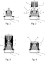
- Nachfolgend wird die Erfindung anhand einer ein Ausführungsbeispiel darstellenden Zeichnung näher erläutert. Deren Figuren zeigen jeweils schematisch:
- Fig. 1 - 10
- verschiedene Phasen der Durchführung des erfindungsgemäßen Verfahrens mit jeweils in einem Schnitt entlang ihrer Längsachse dargestellten Bauteilen.
- Wie beim aus der
WO 2016/016035 A1 bekannten Stand der Technik werden beim erfindungsgemäßen Verfahren Gießformteile und -kerne bereitgestellt. - Die Gießkerne und -formteile sind in konventioneller Weise im Cold-Box-Verfahren aus einem konventionellen Formstoff hergestellt, bei dem es sich um eine Mischung aus einem handelsüblichen Kernsand, einem ebenso handelsüblichen organischen Binder und optional zugegebenen Zusatzstoffen handeln kann, die beispielsweise der besseren Benetzung der Körner des Kernsands durch den Binder dienen. Nach dem Formen werden die erhaltenen Gießkerne und -formteile mit einem Reaktionsgas begast, um den organischen Binder durch eine chemische Reaktion auszuhärten und dadurch den Gießkernen und -formteilen die notwendige Formsteifigkeit zu verleihen.
- Eine Gießform 1 wird aus den so in konventioneller Weise bereitgestellten Gießformteilen und -kernen in ebenso bekannter Weise zu einer als so genanntes "Kernpaket" ausgebildeten Gießform 1 zusammengesetzt. Zusätzlich kann die Gießform 1 aus Stahl oder anderen unzerstörbaren Materialien bestehende Bauteile umfassen. Dazu gehören beispielsweise Kühlkokillen und desgleichen, die in der Gießform 1 angeordnet werden, um durch eine beschleunigte Erstarrung der jeweils mit der Kühlkokille in Berührung kommenden Schmelze eine gerichtete Erstarrung des Gussteils G zu erzielen.
- Die Gießform 1 ist für die gießtechnische Herstellung eines Gussteils G bestimmt, bei dem es sich im vorliegenden Beispiel um ein Zylinderkurbelgehäuse für einen Nutzfahrzeugverbrennungsmotor handelt.
- Ebenso wird neues Füllmaterial, beispielsweise körniges, insbesondere kugeliges, keramisches Granulat mit einer in konventioneller Weise durch Sieben bestimmten Korngröße von 1,5 - 25 mm, bereitgestellt, das Raumtemperatur (typischerweise 18 - 25 °C) aufweist, wobei Füllgut-Temperaturen von bis zu 45 °C hier praxisgerecht sind.
- Im Weiteren können diese Ausgangsmaterialien im Kreislauf wiederverwendet werden, wie nachfolgend erläutert.
- Die in den
Figuren 1 - 8 in verschiedenen Phasen des erfindungsgemäßen Verfahrens dargestellte Einrichtung T weist eine Siebplatte 2 auf, auf der die zum Abgießen einer Eisengussschmelze vorbereitete Gießform 1 platziert ist. - Die Gießform 1 grenzt einen Formhohlraum 3 gegenüber der Umgebung U ab, in den die Eisengussschmelze abgegossen wird, um das Gussteil G zu bilden. Die Eisenschmelze strömt dabei über ein Anschnittsystem in den Formhohlraum 3, das hier der Übersichtlichkeit halber nicht dargestellt ist.
- Die Siebplatte 2 ist mit ihrem Rand auf einem umlaufenden Randabsatz 4 eines Sammelbehälters 5 abgestützt. In die umlaufende Aufstandfläche des Randabsatzes 4 ist ein Dichtelement 6 eingearbeitet.
- Nachdem die Gießform 1 auf der Siebplatte 2 positioniert ist, wird eine ebenfalls zu der Einrichtung T gehörende Einhausung 7 auf den umlaufenden Randabsatz 4 des Sammelbehälters 5 gesetzt. Die Einhausung 7 ist nach Art einer Haube ausgebildet und ummantelt die Gießform 1 an ihren äußeren Umfangsflächen 8. Dabei weist der Umfang des von der Einhausung 7 umgrenzten Raums ein Übermaß gegenüber dem Umfang der Gießform 1 auf, so dass nach dem Aufsetzen der Einhausung 7 auf den Siebboden 2 zwischen der äußeren Umfangsfläche der Gießform 1 und der Innenfläche 9 der Einhausung 7 ein Füllraum 10 gebildet ist. Mit ihrem dem Sammelbehälter 5 zugeordneten Rand sitzt die Einhausung 7 auf dem Dichtelement 6, so dass hier ein dichter Abschluss des Füllraums 10 gegenüber der Umgebung U gewährleistet ist.
- Die Einhausung besteht aus einem Blechmaterial, an dessen thermisch isolierenden Eigenschaften keine besonderen Anforderungen gestellt werden. Dabei ist das Blechmaterial in an sich bekannter Weise so ausgelegt, dass es die notwendige Formstabilität der Einhausung 7 gewährleistet. An ihrer Oberseite umgrenzt die Einhausung 7 eine große Öffnung 11, über die die Gießform 1 mit Eisengussschmelze und der Füllraum 10 mit Füllgut F gefüllt werden kann (
Fig. 2 ). - Zum Befüllen des Füllraums 10 mit dem nicht erhitzten, d.h. mit einer Füllgut-Temperatur, die mindestens gleich der Raumtemperatur ist und höchstens 45 °C beträgt, bereitgestellten Füllgut F wird ein Vorratsbehälter V über der Öffnung 11 positioniert, aus dem man anschließend das untemperierte Füllgut F über ein Verteilsystem 12 in den Füllraum 10 rieseln lässt (
Fig. 3 ). - Wenn der Füllvorgang abgeschlossen ist, kann die in den Füllraum 10 gefüllte Füllgut-Packung erforderlichenfalls verdichtet werden. Anschließend wird ein Deckel 13 auf die Öffnung 11 gesetzt, der ebenfalls eine Öffnung 14 besitzt, über die die Eisengussschmelze in die Gießform 1 gefüllt werden kann (
Fig. 4 ). - Anschließend erfolgt der Abguss der Eisengussschmelze in die Gießform 1 (
Fig. 5 ). - Über einen im unteren Randbereich der Einhausung 7 eingeformten Gaseinlass 15 kann währenddessen sauerstoffhaltige Umgebungsluft in den Füllraum 10 eintreten. Ebenso wird Umgebungsluft, die über einen Zugang 16 in den Sammelbehälter 5 gelangt, durch den Siebboden 2 in den Füllraum 10 gesogen (
Fig. 6 ). - Die mit dem Abguss der Eisengussschmelze einsetzende gewollte Zerstörung der Gießform 1 und die damit einhergehende Entformung des Gussteils G läuft in zwei Phasen ab.
- In der ersten Phase verdampft im Binder enthaltenes Lösemittel. Das aus der Gießform 1 austretende dampfförmige Lösemittel brennt aufgrund der vom Gussteil G abgestrahlten Hitze beim Austreten aus der Gießform 1. Die Verbrennung der aus der Gießform 1 austretenden Binderbestandteile und sonstigen potenziellen Schadstoffe hält ohne weitere Energiezufuhr an, bis kein Binder mehr aus der Gießform 1 ausdampft. Die dann möglicherweise immer noch aus der Gießform 1 austretenden dampfförmigen Stoffe werden durch die im Füllraum 10 herrschende hohe Temperatur oxidiert oder in anderer Weise unschädlich gemacht.
- Ebenso tragen zur Vollständigkeit der Verbrennung der aus der Gießform 1 tretenden Gase die sauerstoffhaltigen, aus Umgebungsluft gebildeten Gasströme S1,S2 bei, die über den Gaseinlass 15 und den Siebboden 2 in den Füllraum 10 der Einhausung 7 gelangen.
- Da die Schüttdichte des Füllguts F so niedrig ist, dass auch nach einer Verdichtung eine gute Gasdurchlässigkeit des im Füllraum 10 vorhandenen Füllgut-Pakets gewährleistet ist, ist eine gute Durchmischung der aus der Gießform 1 austretenden Gase mit dem Sauerstoff für seine Verbrennung bereitstellenden Gasströme S1,S2 gewährleistet. Gleichzeitig stützt die Füllgut-Packung im Füllraum 10 die Gießform 1 an ihren Umfangsflächen 8 und verhindert so ein Durchbrechen der Eisengussschmelze aus der Gießform 1.
- Die Formteile und Kerne der Gießform 1 zerfallen in Bruchstücke B oder einzelne Sandkörner, die durch den Siebboden 2 in den Sammelbehälter 5 fallen und dort gesammelt werden. Abhängig vom Fortschritt der Zerstörung der Gießform 1 kann der Siebboden 2 dabei so geöffnet werden, dass auch Füllgut F in den Sammelbehälter 5 gelangt (
Fig. 7 ). - Der Fortschritt der Zerstörung der Gießform 1 und der Erstarrungsverlauf der in die Gießform 1 gegossenen Eisengussschmelze sind so aneinander angepasst, dass das Gussteil G ausreichend erstarrt ist, wenn der Zerfall der Gießform 1 einsetzt. Die geringe Temperatur des Füllguts F trägt hier dazu bei, dass die Gießform 1 und mit ihr das Gussteil G schnell abkühlen. Auf diese Weise wird eine besonders gute Maßhaltigkeit des Gussteils G erzielt.
- Nachdem die Gießform 1 im Wesentlichen vollständig zerfallen ist, wird der Sammelbehälter 5 mit dem in ihm enthaltenen Formstoff-Füllgut-Gemisch von dem Siebboden 2 getrennt und die Einhausung 7 ebenfalls vom Siebboden 2 abgenommen (
Fig. 8 ). Das weitestgehend entsandete Gussteil G ist nun frei zugänglich und kann in einem hierzu vorgesehenen tunnelartigen Raum 17 kontrolliert abgekühlt werden (Fig. 9 ). - Das Gussteil G hat aufgrund des Prozesses eine hohe Temperatur beim Entnehmen, bei dem die Austenit-Umwandlung noch nicht abgeschlossen ist und eine schnelle Abkühlung zu Eigenspannungen und damit zu Rissen führen würde. Aus diesem Grund wird das Gussteil G in einem Abkühltunnel 17 langsam entsprechend der Glühkurven beim Spannungsarmglühen abgekühlt. Die zugeführte Kühlluft wird so bemessen, dass das Abkühlprofil produktspezifisch erreicht wird.
- Das im Sammelbehälter 5 gesammelte, nach wie vor heiße Gemisch aus Füllgut F, Kernsand und Bruchstücken B wird in der in der
WO 2016/016035 A1 beschriebenen Weise aufbereitet. - Der durch die Aufbereitung erhaltene Kernsand wird zur Erzeugung neuer Gießformteile und -kerne bereitgestellt.
- Das durch die Aufbereitung erhaltene Füllgut F wird an Luft ohne zusätzliche Energiezufuhr auf Raumtemperatur abgekühlt und für eine erneute Befüllung des Füllraums 10 in dem Vorratsbehälter V gelagert.
- Die Erfindung stellt somit ein Verfahren zum Gießen von Gussteilen (G) zur Verfügung, bei dem eine Metallschmelze in eine Gießform 1 abgegossen wird, wobei die Gießform 1 als verlorene Form aus einem oder mehreren Gießformteilen oder -kernen besteht, die aus einem Formstoff geformt sind, der aus einem Kernsand, einem Binder und optional einem oder mehreren Zusätzen zur Einstellung bestimmter
- Eigenschaften des Formstoffs besteht. Im Zuge des erfindungsgemäßen Verfahrens wird
- die jeweilige Gießform 1 bereitgestellt,
- die Gießform 1 in ein Gehäuse 7 unter Ausbildung eines Füllraums 10 zwischen mindestens einem Innenflächenabschnitt 9 des Gehäuses 7 und einem zugeordneten Außenflächenabschnitt 8 der Gießform 1 eingehaust,
- der Füllraum 10 mit einem rieselfähigem Füllgut F gefüllt, das eine so geringe Schüttdichte besitzt, dass die nach dem Befüllen des Füllraums 10 dort aus dem Füllgut F gebildete Füllgutpackung von einer Gasströmung S1,S2 durchströmbar ist, und
- die Metallschmelze in die Gießform 1 abgegossen,
- Indem erfindungsgemäß das Füllgut F beim Einfüllen in den Füllraum 10 eine Füllgut-Temperatur aufweist, die kleiner 100 °C ist, lässt sich bei vermindertem Aufwand die schnelle und energieeffiziente Zersetzung der Gießform 1 erzielen.
-
- 1
- Gießform
- 2
- Siebplatte
- 3
- Formhohlraum
- 4
- um laufender Randabsatz
- 5
- Sammelbehälter
- 6
- Dichtelement
- 7
- Einhausung (Gehäuse)
- 8
- Umfangsflächen der Gießform 1
- 9
- Innenfläche der Einhausung 7
- 10
- Füllraum
- 11
- Öffnung der Einhausung
- 12
- Verteilsystem
- 13
- Deckel
- 14
- Öffnung des Deckels 13
- 15
- Gaseinlass
- 16
- Zugang
- 17
- Abkühltunnel
- B
- Bruchstücke
- F
- Füllgut
- G
- Gussteil
- S1,S2
- sauerstoffhaltige Gasströme
- T
- Einrichtung
- U
- Umgebung
- V
- Vorratsbehälter
Claims (3)
- Verfahren zum Gießen von Gussteilen (G), bei dem eine Metallschmelze in eine Gießform (1) abgegossen wird, die einen das zu erzeugende Gussteil abbildenden Hohlraum (3) umschließt, wobei die Gießform (1) als verlorene Form aus einem oder mehreren Gießformteilen oder -kernen besteht, die aus einem Formstoff geformt sind, der aus einem Kernsand, einem Binder und optional einem oder mehreren Zusätzen zur Einstellung bestimmter Eigenschaften des Formstoffs besteht, umfassend folgende Arbeitsschritte:- Bereitstellen der Gießform (1);- Einhausen der Gießform (1) in ein Gehäuse (7) unter Ausbildung eines Füllraums (10) zwischen mindestens einem Innenflächenabschnitt (9) des Gehäuses (7) und einem zugeordneten Außenflächenabschnitt (8) der Gießform (1);- Befüllen des Füllraums (10) mit einem rieselfähigen Füllgut (F), wobei das in den Füllraum (10) gefüllte Füllgut (F) eine so geringe Schüttdichte besitzt, dass die nach dem Befüllen des Füllraums (10) dort aus dem Füllgut (F) gebildete Füllgutpackung von einer Gasströmung (S1,S2) durchströmbar ist;
und- Abgießen der Metallschmelze in die Gießform (1),dadurch gekennzeichnet, dass das Füllgut (F) beim Einfüllen in den Füllraum (10) eine Füllgut-Temperatur aufweist, die kleiner 100 °C ist.- wobei die Gießform (1) einhergehend mit dem Eingießen der Metallschmelze beginnt, Wärme abzustrahlen, die Folge des durch die heiße Metallschmelze bewirkten Wärmeeintrags ist, und- wobei in Folge des durch die Metallschmelze bewirkten Wärmeeintrags der Binder des Formstoffs zu verdampfen und zu verbrennen beginnt, so dass er seine Wirkung verliert und die Gießform (1) in Bruchstücke (B) zerfällt, - Verfahren nach Anspruch 1, dadurch gekennzeichnet, dass die Füllgut-Temperatur beim Einfüllen des Füllguts (F) in den Füllraum (10) höchstens 45 °C beträgt..
- Verfahren nach Anspruch 1, dadurch gekennzeichnet, dass die Temperatur des Füllguts (F) mindestens gleich der Raumtemperatur ist.
Applications Claiming Priority (2)
| Application Number | Priority Date | Filing Date | Title |
|---|---|---|---|
| DE102021115727.7A DE102021115727A1 (de) | 2021-06-17 | 2021-06-17 | Verfahren zum Gießen von Gussteilen |
| PCT/EP2022/066323 WO2022263517A1 (de) | 2021-06-17 | 2022-06-15 | VERFAHREN ZUM GIEßEN VON GUSSTEILEN |
Publications (3)
| Publication Number | Publication Date |
|---|---|
| EP4355512A1 EP4355512A1 (de) | 2024-04-24 |
| EP4355512B1 true EP4355512B1 (de) | 2025-03-26 |
| EP4355512C0 EP4355512C0 (de) | 2025-03-26 |
Family
ID=82270664
Family Applications (1)
| Application Number | Title | Priority Date | Filing Date |
|---|---|---|---|
| EP22734570.9A Active EP4355512B1 (de) | 2021-06-17 | 2022-06-15 | Verfahren zum giessen von gussteilen |
Country Status (7)
| Country | Link |
|---|---|
| US (1) | US12337377B2 (de) |
| EP (1) | EP4355512B1 (de) |
| JP (1) | JP2024524150A (de) |
| CN (1) | CN117529375A (de) |
| DE (1) | DE102021115727A1 (de) |
| MX (1) | MX2023015274A (de) |
| WO (1) | WO2022263517A1 (de) |
Families Citing this family (1)
| Publication number | Priority date | Publication date | Assignee | Title |
|---|---|---|---|---|
| EP4467939A1 (de) * | 2023-05-24 | 2024-11-27 | Multipond Wägetechnik GmbH | Behälter und behälterzarge |
Family Cites Families (6)
| Publication number | Priority date | Publication date | Assignee | Title |
|---|---|---|---|---|
| US4236568A (en) * | 1978-12-04 | 1980-12-02 | Sherwood Refractories, Inc. | Method of casting steel and iron alloys with precision cristobalite cores |
| JPH0635047B2 (ja) * | 1987-11-06 | 1994-05-11 | トヨタ自動車株式会社 | 中子の除去方法 |
| DE102005046027A1 (de) | 2005-09-05 | 2007-03-08 | HOS Hottinger Systems GbR (vertretungsberechtigter Gesellschafter: Walter Leo Pöhlandt, 68782 Brühl) | Verfahren zum Gießen von Formteilen |
| JPWO2011013730A1 (ja) | 2009-07-31 | 2013-01-10 | 森川産業株式会社 | 鋳造ユニット及び鋳造方法 |
| CN103433428B (zh) * | 2013-09-12 | 2016-01-20 | 赵秋会 | 一种复合铸造方法 |
| DE102014110826A1 (de) * | 2014-07-30 | 2016-02-04 | Fritz Winter Eisengiesserei Gmbh & Co. Kg | Verfahren zum Gießen von Gussteilen |
-
2021
- 2021-06-17 DE DE102021115727.7A patent/DE102021115727A1/de active Pending
-
2022
- 2022-06-15 CN CN202280042946.7A patent/CN117529375A/zh active Pending
- 2022-06-15 MX MX2023015274A patent/MX2023015274A/es unknown
- 2022-06-15 US US18/570,689 patent/US12337377B2/en active Active
- 2022-06-15 EP EP22734570.9A patent/EP4355512B1/de active Active
- 2022-06-15 WO PCT/EP2022/066323 patent/WO2022263517A1/de not_active Ceased
- 2022-06-15 JP JP2023578003A patent/JP2024524150A/ja active Pending
Also Published As
| Publication number | Publication date |
|---|---|
| BR112023025405A2 (pt) | 2024-02-20 |
| WO2022263517A1 (de) | 2022-12-22 |
| US12337377B2 (en) | 2025-06-24 |
| EP4355512C0 (de) | 2025-03-26 |
| US20240278312A1 (en) | 2024-08-22 |
| CN117529375A (zh) | 2024-02-06 |
| JP2024524150A (ja) | 2024-07-05 |
| EP4355512A1 (de) | 2024-04-24 |
| DE102021115727A1 (de) | 2022-12-22 |
| MX2023015274A (es) | 2024-01-23 |
Similar Documents
| Publication | Publication Date | Title |
|---|---|---|
| EP3119545B1 (de) | Verfahren zum giessen von gussteilen | |
| EP2844409B1 (de) | VERFAHREN ZUM GIEßEN EINES MIT MINDESTENS EINER DURCHGANGSÖFFNUNG VERSEHENEN GUSSTEILS | |
| EP0065208A1 (de) | Verfahren und Vorrichtung zur Herstellung von dickwandigen, hohlen Gussstücken | |
| DE2646060A1 (de) | Verfahren und vorrichtungen zur steuerung des waermehaushalts von giessformen | |
| DE102007017690A1 (de) | Verfahren und Vorrichtung zur Herstellung eines Gussteils | |
| EP4355512A1 (de) | VERFAHREN ZUM GIEßEN VON GUSSTEILEN | |
| EP3450050A1 (de) | Vorrichtung zum niederdruckgiessen | |
| EP0890400B1 (de) | Giessverfahren zum Herstellen metallischer Giesslinge | |
| EP3041623B1 (de) | Verfahren zum entformen eines aus leichtmetallschmelze gegossenen gussteils aus einer giessform | |
| DE112006000461T5 (de) | Gießverfahren | |
| EP1960137A1 (de) | Verfahren zum giessen von formteilen | |
| WO2020187981A1 (de) | VERFAHREN UND ANLAGE ZUR HERSTELLUNG EINES GIEßEREIPRODUKTES | |
| EP3666414B1 (de) | Verfahren und gussform zum herstellen von metallgusswerkstücken | |
| WO2005044485A2 (de) | Verfahren zum giessen von formteilen | |
| DE10361535B4 (de) | Verfahren zum Gießen von Formteilen | |
| DE3216327C1 (de) | Herstellung von dickwandigen Abschirmtransport- und Lagerbehältern aus sphärolitischem Gußeisen | |
| DE396867C (de) | Verfahren und Vorrichtung zur Herstellung feuerfester Hohlkoerper, z.B. Ofenfutter oder Schmelztiegel | |
| DE102004013973B4 (de) | Verfahren zum Gießen von Formteilen | |
| DE1145310B (de) | Verfahren zum Herstellen von Formen oder Kernen fuer Giessereizwecke | |
| CH556701A (de) | Verfahren zur herstellung einer giessform. | |
| DE3742766A1 (de) | Verfahren und vorrichtung zur maschinellen herstellung von aus umweltunschaedliche binder enthaltendem modellsand und fuellsand bestehenden kastenlosen giessformteilen | |
| DE2123632B1 (de) | Leicht enfernbare formteile, insbesondere kerne für giessereizwecke und verfahren zu deren herstellung | |
| DE102004027592A1 (de) | Verfahren und Vorrichtung zum speiserarmen oder speiserlosen Gießen untereutektischer Gusseisenlegierungen | |
| DE202004017235U1 (de) | Gußteil |
Legal Events
| Date | Code | Title | Description |
|---|---|---|---|
| STAA | Information on the status of an ep patent application or granted ep patent |
Free format text: STATUS: UNKNOWN |
|
| STAA | Information on the status of an ep patent application or granted ep patent |
Free format text: STATUS: THE INTERNATIONAL PUBLICATION HAS BEEN MADE |
|
| PUAI | Public reference made under article 153(3) epc to a published international application that has entered the european phase |
Free format text: ORIGINAL CODE: 0009012 |
|
| STAA | Information on the status of an ep patent application or granted ep patent |
Free format text: STATUS: REQUEST FOR EXAMINATION WAS MADE |
|
| 17P | Request for examination filed |
Effective date: 20231130 |
|
| AK | Designated contracting states |
Kind code of ref document: A1 Designated state(s): AL AT BE BG CH CY CZ DE DK EE ES FI FR GB GR HR HU IE IS IT LI LT LU LV MC MK MT NL NO PL PT RO RS SE SI SK SM TR |
|
| DAV | Request for validation of the european patent (deleted) | ||
| DAX | Request for extension of the european patent (deleted) | ||
| GRAP | Despatch of communication of intention to grant a patent |
Free format text: ORIGINAL CODE: EPIDOSNIGR1 |
|
| STAA | Information on the status of an ep patent application or granted ep patent |
Free format text: STATUS: GRANT OF PATENT IS INTENDED |
|
| INTG | Intention to grant announced |
Effective date: 20241018 |
|
| GRAS | Grant fee paid |
Free format text: ORIGINAL CODE: EPIDOSNIGR3 |
|
| GRAA | (expected) grant |
Free format text: ORIGINAL CODE: 0009210 |
|
| STAA | Information on the status of an ep patent application or granted ep patent |
Free format text: STATUS: THE PATENT HAS BEEN GRANTED |
|
| AK | Designated contracting states |
Kind code of ref document: B1 Designated state(s): AL AT BE BG CH CY CZ DE DK EE ES FI FR GB GR HR HU IE IS IT LI LT LU LV MC MK MT NL NO PL PT RO RS SE SI SK SM TR |
|
| REG | Reference to a national code |
Ref country code: GB Ref legal event code: FG4D Free format text: NOT ENGLISH |
|
| REG | Reference to a national code |
Ref country code: CH Ref legal event code: EP |
|
| REG | Reference to a national code |
Ref country code: DE Ref legal event code: R096 Ref document number: 502022003347 Country of ref document: DE |
|
| REG | Reference to a national code |
Ref country code: IE Ref legal event code: FG4D Free format text: LANGUAGE OF EP DOCUMENT: GERMAN |
|
| U01 | Request for unitary effect filed |
Effective date: 20250422 |
|
| U07 | Unitary effect registered |
Designated state(s): AT BE BG DE DK EE FI FR IT LT LU LV MT NL PT RO SE SI Effective date: 20250425 |
|
| PG25 | Lapsed in a contracting state [announced via postgrant information from national office to epo] |
Ref country code: RS Free format text: LAPSE BECAUSE OF FAILURE TO SUBMIT A TRANSLATION OF THE DESCRIPTION OR TO PAY THE FEE WITHIN THE PRESCRIBED TIME-LIMIT Effective date: 20250626 |
|
| PG25 | Lapsed in a contracting state [announced via postgrant information from national office to epo] |
Ref country code: NO Free format text: LAPSE BECAUSE OF FAILURE TO SUBMIT A TRANSLATION OF THE DESCRIPTION OR TO PAY THE FEE WITHIN THE PRESCRIBED TIME-LIMIT Effective date: 20250626 |
|
| PG25 | Lapsed in a contracting state [announced via postgrant information from national office to epo] |
Ref country code: HR Free format text: LAPSE BECAUSE OF FAILURE TO SUBMIT A TRANSLATION OF THE DESCRIPTION OR TO PAY THE FEE WITHIN THE PRESCRIBED TIME-LIMIT Effective date: 20250326 |
|
| PG25 | Lapsed in a contracting state [announced via postgrant information from national office to epo] |
Ref country code: GR Free format text: LAPSE BECAUSE OF FAILURE TO SUBMIT A TRANSLATION OF THE DESCRIPTION OR TO PAY THE FEE WITHIN THE PRESCRIBED TIME-LIMIT Effective date: 20250627 |
|
| PGFP | Annual fee paid to national office [announced via postgrant information from national office to epo] |
Ref country code: TR Payment date: 20250603 Year of fee payment: 4 |
|
| U20 | Renewal fee for the european patent with unitary effect paid |
Year of fee payment: 4 Effective date: 20250624 |
|
| PG25 | Lapsed in a contracting state [announced via postgrant information from national office to epo] |
Ref country code: SM Free format text: LAPSE BECAUSE OF FAILURE TO SUBMIT A TRANSLATION OF THE DESCRIPTION OR TO PAY THE FEE WITHIN THE PRESCRIBED TIME-LIMIT Effective date: 20250326 |
|
| PG25 | Lapsed in a contracting state [announced via postgrant information from national office to epo] |
Ref country code: ES Free format text: LAPSE BECAUSE OF FAILURE TO SUBMIT A TRANSLATION OF THE DESCRIPTION OR TO PAY THE FEE WITHIN THE PRESCRIBED TIME-LIMIT Effective date: 20250326 |
|
| PG25 | Lapsed in a contracting state [announced via postgrant information from national office to epo] |
Ref country code: PL Free format text: LAPSE BECAUSE OF FAILURE TO SUBMIT A TRANSLATION OF THE DESCRIPTION OR TO PAY THE FEE WITHIN THE PRESCRIBED TIME-LIMIT Effective date: 20250326 |
|
| PG25 | Lapsed in a contracting state [announced via postgrant information from national office to epo] |
Ref country code: SK Free format text: LAPSE BECAUSE OF FAILURE TO SUBMIT A TRANSLATION OF THE DESCRIPTION OR TO PAY THE FEE WITHIN THE PRESCRIBED TIME-LIMIT Effective date: 20250326 |
|
| PG25 | Lapsed in a contracting state [announced via postgrant information from national office to epo] |
Ref country code: IS Free format text: LAPSE BECAUSE OF FAILURE TO SUBMIT A TRANSLATION OF THE DESCRIPTION OR TO PAY THE FEE WITHIN THE PRESCRIBED TIME-LIMIT Effective date: 20250726 |
|
| PG25 | Lapsed in a contracting state [announced via postgrant information from national office to epo] |
Ref country code: CZ Free format text: LAPSE BECAUSE OF FAILURE TO SUBMIT A TRANSLATION OF THE DESCRIPTION OR TO PAY THE FEE WITHIN THE PRESCRIBED TIME-LIMIT Effective date: 20250326 |
|
| REG | Reference to a national code |
Ref country code: CH Ref legal event code: H13 Free format text: ST27 STATUS EVENT CODE: U-0-0-H10-H13 (AS PROVIDED BY THE NATIONAL OFFICE) Effective date: 20260127 |
|
| PG25 | Lapsed in a contracting state [announced via postgrant information from national office to epo] |
Ref country code: MC Free format text: LAPSE BECAUSE OF FAILURE TO SUBMIT A TRANSLATION OF THE DESCRIPTION OR TO PAY THE FEE WITHIN THE PRESCRIBED TIME-LIMIT Effective date: 20250326 |
|
| PLBE | No opposition filed within time limit |
Free format text: ORIGINAL CODE: 0009261 |
|
| STAA | Information on the status of an ep patent application or granted ep patent |
Free format text: STATUS: NO OPPOSITION FILED WITHIN TIME LIMIT |
|
| REG | Reference to a national code |
Ref country code: CH Ref legal event code: L10 Free format text: ST27 STATUS EVENT CODE: U-0-0-L10-L00 (AS PROVIDED BY THE NATIONAL OFFICE) Effective date: 20260211 |
|
| 26N | No opposition filed |
Effective date: 20260105 |
|
| PG25 | Lapsed in a contracting state [announced via postgrant information from national office to epo] |
Ref country code: IE Free format text: LAPSE BECAUSE OF NON-PAYMENT OF DUE FEES Effective date: 20250615 |
|
| PG25 | Lapsed in a contracting state [announced via postgrant information from national office to epo] |
Ref country code: CH Free format text: LAPSE BECAUSE OF NON-PAYMENT OF DUE FEES Effective date: 20250630 |