EP4354643A1 - Device for compressing joint part between electrode tab and electrode lead - Google Patents
Device for compressing joint part between electrode tab and electrode lead Download PDFInfo
- Publication number
- EP4354643A1 EP4354643A1 EP22916620.2A EP22916620A EP4354643A1 EP 4354643 A1 EP4354643 A1 EP 4354643A1 EP 22916620 A EP22916620 A EP 22916620A EP 4354643 A1 EP4354643 A1 EP 4354643A1
- Authority
- EP
- European Patent Office
- Prior art keywords
- compressing member
- electrode
- electrode lead
- electrode tab
- injection nozzle
- Prior art date
- Legal status (The legal status is an assumption and is not a legal conclusion. Google has not performed a legal analysis and makes no representation as to the accuracy of the status listed.)
- Pending
Links
Images



Classifications
-
- H—ELECTRICITY
- H01—ELECTRIC ELEMENTS
- H01M—PROCESSES OR MEANS, e.g. BATTERIES, FOR THE DIRECT CONVERSION OF CHEMICAL ENERGY INTO ELECTRICAL ENERGY
- H01M50/00—Constructional details or processes of manufacture of the non-active parts of electrochemical cells other than fuel cells, e.g. hybrid cells
- H01M50/50—Current conducting connections for cells or batteries
- H01M50/543—Terminals
- H01M50/564—Terminals characterised by their manufacturing process
- H01M50/567—Terminals characterised by their manufacturing process by fixing means, e.g. screws, rivets or bolts
-
- B—PERFORMING OPERATIONS; TRANSPORTING
- B30—PRESSES
- B30B—PRESSES IN GENERAL
- B30B15/00—Details of, or accessories for, presses; Auxiliary measures in connection with pressing
- B30B15/0082—Dust eliminating means; Mould or press ram cleaning means
-
- H—ELECTRICITY
- H01—ELECTRIC ELEMENTS
- H01M—PROCESSES OR MEANS, e.g. BATTERIES, FOR THE DIRECT CONVERSION OF CHEMICAL ENERGY INTO ELECTRICAL ENERGY
- H01M50/00—Constructional details or processes of manufacture of the non-active parts of electrochemical cells other than fuel cells, e.g. hybrid cells
- H01M50/50—Current conducting connections for cells or batteries
- H01M50/531—Electrode connections inside a battery casing
- H01M50/54—Connection of several leads or tabs of plate-like electrode stacks, e.g. electrode pole straps or bridges
-
- B—PERFORMING OPERATIONS; TRANSPORTING
- B08—CLEANING
- B08B—CLEANING IN GENERAL; PREVENTION OF FOULING IN GENERAL
- B08B5/00—Cleaning by methods involving the use of air flow or gas flow
- B08B5/02—Cleaning by the force of jets, e.g. blowing-out cavities
-
- B—PERFORMING OPERATIONS; TRANSPORTING
- B08—CLEANING
- B08B—CLEANING IN GENERAL; PREVENTION OF FOULING IN GENERAL
- B08B5/00—Cleaning by methods involving the use of air flow or gas flow
- B08B5/04—Cleaning by suction, with or without auxiliary action
-
- H—ELECTRICITY
- H01—ELECTRIC ELEMENTS
- H01M—PROCESSES OR MEANS, e.g. BATTERIES, FOR THE DIRECT CONVERSION OF CHEMICAL ENERGY INTO ELECTRICAL ENERGY
- H01M10/00—Secondary cells; Manufacture thereof
- H01M10/04—Construction or manufacture in general
- H01M10/0404—Machines for assembling batteries
-
- H—ELECTRICITY
- H01—ELECTRIC ELEMENTS
- H01M—PROCESSES OR MEANS, e.g. BATTERIES, FOR THE DIRECT CONVERSION OF CHEMICAL ENERGY INTO ELECTRICAL ENERGY
- H01M10/00—Secondary cells; Manufacture thereof
- H01M10/04—Construction or manufacture in general
- H01M10/0481—Compression means other than compression means for stacks of electrodes and separators
-
- H—ELECTRICITY
- H01—ELECTRIC ELEMENTS
- H01M—PROCESSES OR MEANS, e.g. BATTERIES, FOR THE DIRECT CONVERSION OF CHEMICAL ENERGY INTO ELECTRICAL ENERGY
- H01M10/00—Secondary cells; Manufacture thereof
- H01M10/05—Accumulators with non-aqueous electrolyte
- H01M10/052—Li-accumulators
-
- H—ELECTRICITY
- H01—ELECTRIC ELEMENTS
- H01M—PROCESSES OR MEANS, e.g. BATTERIES, FOR THE DIRECT CONVERSION OF CHEMICAL ENERGY INTO ELECTRICAL ENERGY
- H01M50/00—Constructional details or processes of manufacture of the non-active parts of electrochemical cells other than fuel cells, e.g. hybrid cells
- H01M50/10—Primary casings; Jackets or wrappings
- H01M50/14—Primary casings; Jackets or wrappings for protecting against damage caused by external factors
-
- H—ELECTRICITY
- H01—ELECTRIC ELEMENTS
- H01M—PROCESSES OR MEANS, e.g. BATTERIES, FOR THE DIRECT CONVERSION OF CHEMICAL ENERGY INTO ELECTRICAL ENERGY
- H01M50/00—Constructional details or processes of manufacture of the non-active parts of electrochemical cells other than fuel cells, e.g. hybrid cells
- H01M50/20—Mountings; Secondary casings or frames; Racks, modules or packs; Suspension devices; Shock absorbers; Transport or carrying devices; Holders
- H01M50/296—Mountings; Secondary casings or frames; Racks, modules or packs; Suspension devices; Shock absorbers; Transport or carrying devices; Holders characterised by terminals of battery packs
-
- H—ELECTRICITY
- H01—ELECTRIC ELEMENTS
- H01M—PROCESSES OR MEANS, e.g. BATTERIES, FOR THE DIRECT CONVERSION OF CHEMICAL ENERGY INTO ELECTRICAL ENERGY
- H01M50/00—Constructional details or processes of manufacture of the non-active parts of electrochemical cells other than fuel cells, e.g. hybrid cells
- H01M50/50—Current conducting connections for cells or batteries
- H01M50/531—Electrode connections inside a battery casing
- H01M50/533—Electrode connections inside a battery casing characterised by the shape of the leads or tabs
-
- H—ELECTRICITY
- H01—ELECTRIC ELEMENTS
- H01M—PROCESSES OR MEANS, e.g. BATTERIES, FOR THE DIRECT CONVERSION OF CHEMICAL ENERGY INTO ELECTRICAL ENERGY
- H01M50/00—Constructional details or processes of manufacture of the non-active parts of electrochemical cells other than fuel cells, e.g. hybrid cells
- H01M50/50—Current conducting connections for cells or batteries
- H01M50/531—Electrode connections inside a battery casing
- H01M50/536—Electrode connections inside a battery casing characterised by the method of fixing the leads to the electrodes, e.g. by welding
-
- H—ELECTRICITY
- H01—ELECTRIC ELEMENTS
- H01M—PROCESSES OR MEANS, e.g. BATTERIES, FOR THE DIRECT CONVERSION OF CHEMICAL ENERGY INTO ELECTRICAL ENERGY
- H01M50/00—Constructional details or processes of manufacture of the non-active parts of electrochemical cells other than fuel cells, e.g. hybrid cells
- H01M50/50—Current conducting connections for cells or batteries
- H01M50/572—Means for preventing undesired use or discharge
- H01M50/584—Means for preventing undesired use or discharge for preventing incorrect connections inside or outside the batteries
- H01M50/59—Means for preventing undesired use or discharge for preventing incorrect connections inside or outside the batteries characterised by the protection means
- H01M50/593—Spacers; Insulating plates
-
- H—ELECTRICITY
- H01—ELECTRIC ELEMENTS
- H01M—PROCESSES OR MEANS, e.g. BATTERIES, FOR THE DIRECT CONVERSION OF CHEMICAL ENERGY INTO ELECTRICAL ENERGY
- H01M10/00—Secondary cells; Manufacture thereof
- H01M10/05—Accumulators with non-aqueous electrolyte
- H01M10/052—Li-accumulators
- H01M10/0525—Rocking-chair batteries, i.e. batteries with lithium insertion or intercalation in both electrodes; Lithium-ion batteries
-
- Y—GENERAL TAGGING OF NEW TECHNOLOGICAL DEVELOPMENTS; GENERAL TAGGING OF CROSS-SECTIONAL TECHNOLOGIES SPANNING OVER SEVERAL SECTIONS OF THE IPC; TECHNICAL SUBJECTS COVERED BY FORMER USPC CROSS-REFERENCE ART COLLECTIONS [XRACs] AND DIGESTS
- Y02—TECHNOLOGIES OR APPLICATIONS FOR MITIGATION OR ADAPTATION AGAINST CLIMATE CHANGE
- Y02E—REDUCTION OF GREENHOUSE GAS [GHG] EMISSIONS, RELATED TO ENERGY GENERATION, TRANSMISSION OR DISTRIBUTION
- Y02E60/00—Enabling technologies; Technologies with a potential or indirect contribution to GHG emissions mitigation
- Y02E60/10—Energy storage using batteries
Definitions
- the present invention relates to an apparatus for compressing a joint of an electrode tab and an electrode lead.
- lithium secondary batteries such as lithium ion secondary batteries and lithium ion polymer secondary batteries having high energy density, discharge voltage, and output stability are being actively conducted.
- the lithium secondary battery is classified according to a structure of an electrode assembly formed of a cathode, an anode, and a separator, in which examples of representative electrode assemblies may include a jelly-roll type (wound type) electrode assembly having a structure in which long sheet-type cathodes and anodes are wound with a separator interposed therebetween, a stack type (laminate type) electrode assembly in which a plurality of cathodes and anodes cut in units of a predetermined size are sequentially stacked with a separator interposed therebetween, and a stack/folding type electrode assembly having a structure where bi-cells or full cells in which cathodes and anodes in predetermined units are stacked with separators interposed therebetween are wound, and the like.
- a jelly-roll type (wound type) electrode assembly having a structure in which long sheet-type cathodes and anodes are wound with a separator interposed therebetween
- a stack type (laminate type) electrode assembly in which
- the process of manufacturing such an electrode assembly includes a process of manufacturing cathode and anode slurries, a process of manufacturing electrode sheets composed of cathodes and an anodes by applying the respective slurries to cathode current collectors and anode current collectors, respectively, a process of pressing the electrode sheets, a process of slitting the electrode sheets according to cell specifications, a vacuum drying process, a process of manufacturing electrodes by forming electrode tabs on the electrode assembly, and a process of manufacturing the electrode assembly in a jelly-roll type, a stack type, etc., by stacking the plurality of cathodes and anodes with a separator interposed therebetween.
- the conventional compression process does not provide a method or apparatus capable of efficiently managing these foreign matters.
- the present invention has been made to solve the problems of the related art as described above, and it is an object of the present invention to provide an apparatus for compressing a joint of an electrode tab and an electrode lead capable of effectively preventing a body of an electrode assembly from being contaminated due to foreign matters during compression of the joint of the electrode tab and the electrode lead formed on the electrode assembly.
- the present invention provides an apparatus for compressing a joint of an electrode tab formed on an electrode assembly and an electrode lead, including:
- the air injection nozzle may be installed to inject air in a direction forming an angle of 10° to 80° with respect to the joining surface of the fed electrode tab and electrode lead.
- the air injection nozzle may be controlled not to operate at the compressed position of the upper compressing member and the lower compressing member, and to operate at a non-compressed position of the upper compressing member and the lower compressing member.
- the air injection nozzle may be controlled to operate when the joint of the electrode tab and the electrode lead is fed in a state where the upper compressing member is raised, not to operate from a time when the upper compressing member is lowered to a time when the upper compressing member is raised through a compression process, and to operate again when the joint of the electrode tab and electrode lead is discharged after the compression is completed.
- the lower support member may further include an air injection nozzle that injects air obliquely from an outside of the lower compressing member toward the joining surface of the electrode tab and the electrode lead.
- the air injection nozzle included in the lower support member may be installed to inject air in a direction forming an angle of 10° to 80° with respect to the joining surface of the fed electrode tab and electrode lead.
- the air injection nozzle included in lower support member may be controlled not to operate at the compressed position of the upper compressing member and the lower compressing member, and to operate at the non-compressed position of the upper compressing member and the lower compressing member.
- the air injection nozzle included in the lower support member may be controlled to operate when the joint of the electrode tab and the electrode lead is fed in a state where the lower compressing member is lowered, and not to operate from a time when the lower compressing member is raised to a time when the lower compressing member is lowered through a compression process, and to operate again when the joint of the electrode tab and electrode lead is discharged after the compression is completed.
- the foreign matter suction unit may include a suction pipe that communicates with a space opposite to the electrode assembly being fed based on the compressed position of the upper compressing member and the lower compressing member and an inhaler that is connected to the suction pipe.
- An apparatus for compressing a joint of an electrode tab and an electrode lead of the present invention prevents contamination of a body of an electrode assembly by foreign matters when the joint of the electrode tab and the electrode lead formed on the electrode assembly is compressed by a structure of an air injection device, and, furthermore, significantly improves the anti-contamination effect as described above by controlling the operation of the air injection device.
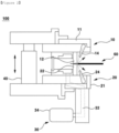
- FIG. 1 is a cross-sectional view schematically illustrating an embodiment of an apparatus for compressing a joint of an electrode tab and an electrode lead of the present invention
- FIG. 3 is a cross-sectional view schematically illustrating one state of use of the apparatus for compressing a joint of an electrode tab and an electrode lead of the present invention
- FIG. 4 is a cross-sectional view schematically illustrating another state of use of the apparatus for compressing a joint of an electrode tab and an electrode lead of the present invention
- FIG. 5 is a cross-sectional view schematically illustrating a form of an electrode assembly.
- An apparatus 100 for compressing a joint of an electrode tab and an electrode lead of the present invention is an apparatus for compressing a joint 66 of an electrode tab 62 formed on an electrode assembly 60 and an electrode lead 64, the apparatus including an upper pressing unit 10; a lower pressing unit 20; a driving unit 40 that drives the upper pressing unit 10 and the lower pressing unit 20 up and down; and a foreign matter suction unit 30 that sucks foreign matters,
- the apparatus for compressing a joint of an electrode tab and an electrode lead 100 of the present invention may be used in a process of compressing a joint of an electrode tab and an electrode lead included in an electrode assembly of a jelly-roll type, a stack type, a stack/folding type, and the like.
- the joint 66 of the electrode tab and the electrode lead of the electrode assembly 60 is fed between the upper compressing member 12 and the lower compressing member 22, and in this case, a body 61 of the electrode assembly may be located outside the upper compressing member 12 and the lower compressing member 22.
- the apparatus for compressing a joint of an electrode tab and an electrode lead 100 of the present invention may include the air injection nozzle 14 that is installed to inject air obliquely from the outside of the upper compressing member 12 toward the joining surface of the fed electrode tab and electrode lead, thereby effectively removing foreign matters present in the electrode tab, the electrode lead, and the joint of the electrode tab and the electrode lead during the compression process.
- foreign matters moved from the electrode tab, the electrode lead, and the joint of the electrode tab and the electrode lead into the apparatus for compressing a joint of an electrode tab and an electrode lead 100 by the air injection of the air injection nozzle 14 are sucked by the foreign matter suction unit 30.
- the air injection nozzle 14 may be installed to inject air in a direction forming an angle of 10° to 80°, preferably 30° to 60° with respect to the joining surfaces of the fed electrode tab and electrode lead. When the air is injected at the above angle, foreign matters may be removed more effectively.
- the operation of the air injection nozzle 14 needs to be controlled so that foreign matter does not contaminate the body of the electrode assembly 60. That is, as illustrated in FIG. 2 , when air is injected by the air injection nozzle 14 at the compressed position (closed state) of the upper compressing member 12 and the lower compressing member 22, the injected air is blocked by the closed upper compressing member 12 and lower compressing member 22 and flows toward the body 61 of the electrode assembly. In this case, the problem that foreign matters contaminate the body 61 of the electrode assembly is caused.
- the air injection nozzle 14 may be controlled not to operate at the compressed position (closed state) of the upper compressing member 12 and the lower compressing member 22 ( FIG. 3B ), and to operate at a non-compressed position (open state) of the upper compressing member 12 and the lower compressing member 22 ( FIG. 3A ).
- the air injection of the air injection nozzle 14 may be controlled to be performed only in a state where the upper compressing member 12 and the lower compressing member 22 are separated by 3 mm or more, preferably 5 mm or more, and more preferably 10 mm or more.
- the air injection nozzle 14 does not operate not only when the upper compressing member 12 and the lower compressing member 22 are in the closed state, but also when the separation distance is less than the above range.
- the air injection nozzle 14 operates only in the state where the separation distance is formed as described above, foreign matters may be more effectively prevented from flowing into the body 61 of the electrode assembly.
- the air injection nozzle 14 may be controlled to operate when the joint of the electrode tab and the electrode lead formed on the electrode assembly 60 is fed in the state where the upper compressing member 12 is raised, not to operate from the time when the upper compressing member 12 is lowered to the time when the upper compressing member is raised through the compression process, and operate again when the joint of the electrode tab and electrode lead is discharged after the compression is completed.
- the air injection nozzle 14 operates according to the above conditions, it is possible to more effectively prevent foreign matters from flowing into the body of the electrode assembly 60.
- the lower support member 21 may further include the air injection nozzle 24 that injects air obliquely from the outside of the lower compressing member 22 toward the joining surface of the electrode tab and the electrode lead formed on the electrode assembly 60.
- the air injection nozzle 24 may be installed to inject air in a direction forming an angle of 10° to 80°, preferably 30° to 70° with respect to the joining surfaces of the fed electrode tab and electrode lead. When the air is injected at the above angle, foreign matters may be removed more effectively.
- the air injection nozzle 24 may be controlled not to operate at the compressed position (closed state) of the upper compressing member 12 and the lower compressing member 22 ( FIG. 3B ), and to operate at a non-compressed position (open state) of the upper compressing member 12 and the lower compressing member 22 ( FIG. 3A ).
- the air injection of the air injection nozzle 24 may be controlled to be performed only in a state where the upper compressing member 12 and the lower compressing member 22 are separated by 3 mm or more, preferably 5 mm or more, and more preferably 10 mm or more.
- the air injection nozzle 24 does not operate not only when the upper compressing member 12 and the lower compressing member 22 are in the closed state, but also when the separation distance is less than the above range.
- the air injection nozzle 24 operates only in the state where the separation distance is formed, it is possible to more effectively prevent foreign matters from flowing into the body of the electrode assembly 60.
- the air injection nozzle 24 included in the lower compressing member 22 may be controlled to operate when the joint 66 of the electrode tab and the electrode lead is fed in the state where the lower compressing member 22 is lowered, and not to operate from the time when the lower compressing member 22 is raised to the time when the lower compressing member 22 is lowered through the compression process, and to operate again when the joint of the electrode tab and electrode lead is discharged after the compression is completed.
- the air injection nozzle 24 operates according to the above conditions, it is possible to more effectively prevent foreign matters from flowing into the body of the electrode assembly 60.
- the upper compressing member 12 and the lower compressing member 22 may be driven to be repeatedly closed and opened by the raising and lowering of the upper support member 11 and the lower support member 21 by a driving device 40.
- the lower pressing unit 20 may be provided to raise and lower only the upper pressing unit 10 in a fixed state.
- the foreign matter suction unit 30 may include a suction pipe 32 that communicates with a space opposite to the electrode assembly based on the upper compressing member 12 and the lower compressing member 22 and an inhaler 34 that is connected to the suction pipe.
Landscapes
- Chemical & Material Sciences (AREA)
- Chemical Kinetics & Catalysis (AREA)
- Electrochemistry (AREA)
- General Chemical & Material Sciences (AREA)
- Engineering & Computer Science (AREA)
- Manufacturing & Machinery (AREA)
- Mechanical Engineering (AREA)
- Connection Of Batteries Or Terminals (AREA)
- Compressor (AREA)
Abstract

Description
- This application claims the benefit of priority based on
Korean Patent Application No. 10-2021-0188275 filed on December 27, 2021 - The present invention relates to an apparatus for compressing a joint of an electrode tab and an electrode lead.
- As the technology development and demand for mobile devices increase, a demand for batteries as an energy source has rapidly increased. Accordingly, many studies on the batteries that may satisfy various demands have been conducted. In particular, studies on lithium secondary batteries such as lithium ion secondary batteries and lithium ion polymer secondary batteries having high energy density, discharge voltage, and output stability are being actively conducted.
- The lithium secondary battery is classified according to a structure of an electrode assembly formed of a cathode, an anode, and a separator, in which examples of representative electrode assemblies may include a jelly-roll type (wound type) electrode assembly having a structure in which long sheet-type cathodes and anodes are wound with a separator interposed therebetween, a stack type (laminate type) electrode assembly in which a plurality of cathodes and anodes cut in units of a predetermined size are sequentially stacked with a separator interposed therebetween, and a stack/folding type electrode assembly having a structure where bi-cells or full cells in which cathodes and anodes in predetermined units are stacked with separators interposed therebetween are wound, and the like.
- The process of manufacturing such an electrode assembly includes a process of manufacturing cathode and anode slurries, a process of manufacturing electrode sheets composed of cathodes and an anodes by applying the respective slurries to cathode current collectors and anode current collectors, respectively, a process of pressing the electrode sheets, a process of slitting the electrode sheets according to cell specifications, a vacuum drying process, a process of manufacturing electrodes by forming electrode tabs on the electrode assembly, and a process of manufacturing the electrode assembly in a jelly-roll type, a stack type, etc., by stacking the plurality of cathodes and anodes with a separator interposed therebetween.
- Thereafter, a process of welding the electrode tabs of the manufactured electrode assembly, welding an electrode leads to the welded electrode tabs, and compressing joints of the electrode tabs and the electrode leads is performed.
- In the case of a process of compressing the joint of the electrode tab and the electrode lead, since foreign matters generated during in the process of manufacturing an electrode assembly are present in an electrode tab part, an electrode lead part, and a joint of the electrode tab part and the electrode lead part, and foreign matters are generated during the compressing process, it is important to efficiently remove the foreign matters. This is because these foreign matters may act as a cause of contaminating a body of the electrode assembly (see
FIGS. 2 and5 ) . - However, the conventional compression process does not provide a method or apparatus capable of efficiently managing these foreign matters.
-
Korean Patent Laid-open Publication No. 10-2014-0113646 - The present invention has been made to solve the problems of the related art as described above, and
it is an object of the present invention to provide an apparatus for compressing a joint of an electrode tab and an electrode lead capable of effectively preventing a body of an electrode assembly from being contaminated due to foreign matters during compression of the joint of the electrode tab and the electrode lead formed on the electrode assembly. - To achieve the above object,
the present invention provides an apparatus for compressing a joint of an electrode tab formed on an electrode assembly and an electrode lead, including: - an upper pressing unit; a lower pressing unit; a driving unit that drives the upper pressing unit and the lower pressing unit up and down; and a foreign matter suction unit,
- wherein the upper pressing unit includes an upper compressing member protruding downward and an upper support member in which the upper compressing member is fixed to a lower portion, and the lower pressing unit includes a lower compressing member protruding upward and a lower support member in which the lower compressing member is fixed to an upper portion,
- the upper compressing member and the lower compressing member are located in opposite directions on the same line, and are moved to a compressed position by driving the upper support member and the lower support member or separated in opposite directions to each other, and
- the upper support member includes an air injection nozzle that injects air obliquely from an outside of the upper compressing member toward a joining surface of the fed electrode tab and electrode lead.
- In one embodiment of the present invention, the air injection nozzle may be installed to inject air in a direction forming an angle of 10° to 80° with respect to the joining surface of the fed electrode tab and electrode lead.
- In one embodiment of the present invention, the air injection nozzle may be controlled not to operate at the compressed position of the upper compressing member and the lower compressing member, and to operate at a non-compressed position of the upper compressing member and the lower compressing member.
- In one embodiment of the present invention, the air injection nozzle may be controlled to operate when the joint of the electrode tab and the electrode lead is fed in a state where the upper compressing member is raised, not to operate from a time when the upper compressing member is lowered to a time when the upper compressing member is raised through a compression process, and to operate again when the joint of the electrode tab and electrode lead is discharged after the compression is completed.
- In one embodiment of the present invention, the lower support member may further include an air injection nozzle that injects air obliquely from an outside of the lower compressing member toward the joining surface of the electrode tab and the electrode lead.
- In one embodiment of the present invention, the air injection nozzle included in the lower support member may be installed to inject air in a direction forming an angle of 10° to 80° with respect to the joining surface of the fed electrode tab and electrode lead.
- In one embodiment of the present invention, the air injection nozzle included in lower support member may be controlled not to operate at the compressed position of the upper compressing member and the lower compressing member, and to operate at the non-compressed position of the upper compressing member and the lower compressing member.
- In one embodiment of the present invention, the air injection nozzle included in the lower support member may be controlled to operate when the joint of the electrode tab and the electrode lead is fed in a state where the lower compressing member is lowered, and not to operate from a time when the lower compressing member is raised to a time when the lower compressing member is lowered through a compression process, and to operate again when the joint of the electrode tab and electrode lead is discharged after the compression is completed.
- In one embodiment of the present invention, the foreign matter suction unit may include a suction pipe that communicates with a space opposite to the electrode assembly being fed based on the compressed position of the upper compressing member and the lower compressing member and an inhaler that is connected to the suction pipe.
- An apparatus for compressing a joint of an electrode tab and an electrode lead of the present invention prevents contamination of a body of an electrode assembly by foreign matters when the joint of the electrode tab and the electrode lead formed on the electrode assembly is compressed by a structure of an air injection device, and, furthermore, significantly improves the anti-contamination effect as described above by controlling the operation of the air injection device.
-
-
FIG. 1 is a cross-sectional view schematically illustrating an embodiment of an apparatus for compressing a joint of an electrode tab and an electrode lead of the present invention. -
FIG. 2 is a cross-sectional view schematically illustrating a case where the electrode assembly is contaminated by air blowing when using the apparatus for compressing a joint of an electrode tab and an electrode lead of the present invention. -
FIG. 3 is a cross-sectional view schematically illustrating one state of use of the apparatus for compressing a joint of an electrode tab and an electrode lead of the present invention. -
FIG. 4 is a cross-sectional view schematically illustrating another state of use of the apparatus for compressing a joint of an electrode tab and an electrode lead of the present invention. -
FIG. 5 is a cross-sectional view schematically illustrating a form of an electrode assembly. - Hereinafter, the embodiments of the present invention will be described in detail with reference to the accompanying drawings so that those skilled in the art may easily practice the present invention. However, the present invention may be implemented in various different forms, and is not limited to embodiments described herein. Throughout the present disclosure, similar components will be denoted by the same reference numerals.
- When one element is referred to as being "connected to, provided with, or installed in" another element, it should be understood that it may be directly connected to or installed in another element, but other elements may be interposed therebetween. On the other hand, when one element is referred to as being "directly connected to, provided with, or installed in" another element, it should be understood that other elements are not interposed therebetween. Meanwhile, other expressions describing a relationship between components, that is, "upper portion ~", "directly upper portion ~", or "between ~", "directly between ~", or "adjacent to ~," "directly adjacent to ~" and the like, should also be interpreted in the same way.
-
FIG. 1 is a cross-sectional view schematically illustrating an embodiment of an apparatus for compressing a joint of an electrode tab and an electrode lead of the present invention,FIG. 3 is a cross-sectional view schematically illustrating one state of use of the apparatus for compressing a joint of an electrode tab and an electrode lead of the present invention,FIG. 4 is a cross-sectional view schematically illustrating another state of use of the apparatus for compressing a joint of an electrode tab and an electrode lead of the present invention, andFIG. 5 is a cross-sectional view schematically illustrating a form of an electrode assembly. - An
apparatus 100 for compressing a joint of an electrode tab and an electrode lead of the present invention is an apparatus for compressing ajoint 66 of anelectrode tab 62 formed on anelectrode assembly 60 and anelectrode lead 64, the apparatus including an upperpressing unit 10; a lowerpressing unit 20; adriving unit 40 that drives the upperpressing unit 10 and the lowerpressing unit 20 up and down; and a foreignmatter suction unit 30 that sucks foreign matters, - wherein the upper pressing
unit 10 includes an upper compressingmember 12 protruding downward and anupper support member 11 in which the upper compressing member is fixed to a lower portion, and the lowerpressing unit 20 includes a lower compressingmember 22 protruding upward and alower support member 21 in which the lower compressing member is fixed to an upper portion, - the upper compressing
member 12 and the lower compressingmember 22 are located in opposite directions on the same line, and are moved to a compressed position by driving theupper support member 11 and thelower support member 21 or separated in opposite directions to each other, and - the
upper support member 11 includes anair injection nozzle 14 that injects air obliquely from an outside of the upper compressingmember 12 toward a joining surface of the fed electrode tab and electrode lead. - The apparatus for compressing a joint of an electrode tab and an
electrode lead 100 of the present invention may be used in a process of compressing a joint of an electrode tab and an electrode lead included in an electrode assembly of a jelly-roll type, a stack type, a stack/folding type, and the like. - The
joint 66 of the electrode tab and the electrode lead of theelectrode assembly 60 is fed between the upper compressingmember 12 and the lower compressingmember 22, and in this case, abody 61 of the electrode assembly may be located outside the upper compressingmember 12 and the lower compressingmember 22. - As illustrated in
FIG. 1 , the apparatus for compressing a joint of an electrode tab and anelectrode lead 100 of the present invention may include theair injection nozzle 14 that is installed to inject air obliquely from the outside of the upper compressingmember 12 toward the joining surface of the fed electrode tab and electrode lead, thereby effectively removing foreign matters present in the electrode tab, the electrode lead, and the joint of the electrode tab and the electrode lead during the compression process. In addition, as described above, foreign matters moved from the electrode tab, the electrode lead, and the joint of the electrode tab and the electrode lead into the apparatus for compressing a joint of an electrode tab and anelectrode lead 100 by the air injection of theair injection nozzle 14 are sucked by the foreignmatter suction unit 30. - In one embodiment of the present invention, the
air injection nozzle 14 may be installed to inject air in a direction forming an angle of 10° to 80°, preferably 30° to 60° with respect to the joining surfaces of the fed electrode tab and electrode lead. When the air is injected at the above angle, foreign matters may be removed more effectively. - In one embodiment of the present invention, when using the apparatus for compressing a joint of an electrode tab and an
electrode lead 100, the operation of theair injection nozzle 14 needs to be controlled so that foreign matter does not contaminate the body of theelectrode assembly 60. That is, as illustrated inFIG. 2 , when air is injected by theair injection nozzle 14 at the compressed position (closed state) of the upper compressingmember 12 and the lower compressingmember 22, the injected air is blocked by the closed upper compressingmember 12 and lower compressingmember 22 and flows toward thebody 61 of the electrode assembly. In this case, the problem that foreign matters contaminate thebody 61 of the electrode assembly is caused. - Therefore, in the apparatus for compressing a joint of an electrode tab and an
electrode lead 100 of the present invention, as illustrated inFIG. 3 , theair injection nozzle 14 may be controlled not to operate at the compressed position (closed state) of the upper compressingmember 12 and the lower compressing member 22 (FIG. 3B ), and to operate at a non-compressed position (open state) of the upper compressingmember 12 and the lower compressing member 22 (FIG. 3A ). - Furthermore, the air injection of the
air injection nozzle 14 may be controlled to be performed only in a state where the upper compressingmember 12 and thelower compressing member 22 are separated by 3 mm or more, preferably 5 mm or more, and more preferably 10 mm or more. In this case, theair injection nozzle 14 does not operate not only when the upper compressingmember 12 and thelower compressing member 22 are in the closed state, but also when the separation distance is less than the above range. When theair injection nozzle 14 operates only in the state where the separation distance is formed as described above, foreign matters may be more effectively prevented from flowing into thebody 61 of the electrode assembly. - In the present invention, since the operation of the
air injection nozzle 14 may be controlled by a control process commonly used in this field, detailed descriptions thereof will be omitted. - In one embodiment of the present invention, as illustrated in
FIG. 4 , theair injection nozzle 14 may be controlled to operate when the joint of the electrode tab and the electrode lead formed on theelectrode assembly 60 is fed in the state where the upper compressingmember 12 is raised, not to operate from the time when the upper compressingmember 12 is lowered to the time when the upper compressing member is raised through the compression process, and operate again when the joint of the electrode tab and electrode lead is discharged after the compression is completed. When theair injection nozzle 14 operates according to the above conditions, it is possible to more effectively prevent foreign matters from flowing into the body of theelectrode assembly 60. - In one embodiment of the present invention, as illustrated in
FIG. 3 , thelower support member 21 may further include theair injection nozzle 24 that injects air obliquely from the outside of thelower compressing member 22 toward the joining surface of the electrode tab and the electrode lead formed on theelectrode assembly 60. - In one embodiment of the present invention, the
air injection nozzle 24 may be installed to inject air in a direction forming an angle of 10° to 80°, preferably 30° to 70° with respect to the joining surfaces of the fed electrode tab and electrode lead. When the air is injected at the above angle, foreign matters may be removed more effectively. - In one embodiment of the present invention, as illustrated in
FIG. 3 , theair injection nozzle 24 may be controlled not to operate at the compressed position (closed state) of the upper compressingmember 12 and the lower compressing member 22 (FIG. 3B ), and to operate at a non-compressed position (open state) of the upper compressingmember 12 and the lower compressing member 22 (FIG. 3A ). - Furthermore, the air injection of the
air injection nozzle 24 may be controlled to be performed only in a state where the upper compressingmember 12 and thelower compressing member 22 are separated by 3 mm or more, preferably 5 mm or more, and more preferably 10 mm or more. In this case, theair injection nozzle 24 does not operate not only when the upper compressingmember 12 and thelower compressing member 22 are in the closed state, but also when the separation distance is less than the above range. When theair injection nozzle 24 operates only in the state where the separation distance is formed, it is possible to more effectively prevent foreign matters from flowing into the body of theelectrode assembly 60. - In the present invention, since the operation of the
air injection nozzle 24 may be controlled by a control process commonly used in this field, detailed descriptions thereof will be omitted. - In one embodiment of the present invention, as illustrated in
FIG. 4 , theair injection nozzle 24 included in thelower compressing member 22 may be controlled to operate when the joint 66 of the electrode tab and the electrode lead is fed in the state where thelower compressing member 22 is lowered, and not to operate from the time when thelower compressing member 22 is raised to the time when thelower compressing member 22 is lowered through the compression process, and to operate again when the joint of the electrode tab and electrode lead is discharged after the compression is completed. When theair injection nozzle 24 operates according to the above conditions, it is possible to more effectively prevent foreign matters from flowing into the body of theelectrode assembly 60. - In one embodiment of the present invention, the upper compressing
member 12 and thelower compressing member 22 may be driven to be repeatedly closed and opened by the raising and lowering of theupper support member 11 and thelower support member 21 by a drivingdevice 40. In addition, the lower pressingunit 20 may be provided to raise and lower only the upper pressingunit 10 in a fixed state. - In one embodiment of the present invention, the foreign
matter suction unit 30 may include asuction pipe 32 that communicates with a space opposite to the electrode assembly based on the upper compressingmember 12 and thelower compressing member 22 and aninhaler 34 that is connected to the suction pipe. - Although the present invention has been described in relation to the above-described embodiments, various modifications and alterations may be made without departing from the gist and scope of the present invention. Accordingly, these modifications and alterations fall within the scope of the claims as long as they belong to the gist of the present invention.
[Description of Reference Signs] 10: Upper pressing unit 11: Upper support member 12: Upper compressing member 14: Air injection nozzle 20: Lower pressing unit 21: Lower support member 22: Lower compressing member 24: Air injection nozzle 30: Foreign matter suction unit 32: Suction pipe 34: Inhaler 40: Driving unit 60: Electrode assembly 62: Electrode tab 64: Electrode lead 66: Joint of electrode tab and electrode lead 100: Apparatus for compressing joint of electrode tab and electrode lead
Claims (9)
- An apparatus for compressing a joint of an electrode tab formed on an electrode assembly and an electrode lead, the apparatus comprising:an upper pressing unit; a lower pressing unit; a driving unit that drives the upper pressing unit and the lower pressing unit up and down; and a foreign matter suction unit,wherein the upper pressing unit comprises an upper compressing member protruding downward and an upper support member in which the upper compressing member is fixed to a lower portion, and the lower pressing unit comprises a lower compressing member protruding upward and a lower support member in which the lower compressing member is fixed to an upper portion,the upper compressing member and the lower compressing member are located in opposite directions on the same line, and are moved to a compressed position by driving the upper support member and the lower support member or separated in opposite directions to each other, andthe upper support member comprises an air injection nozzle that injects air obliquely from an outside of the upper compressing member toward a joining surface of the fed electrode tab and electrode lead.
- The apparatus of claim 1, wherein the air injection nozzle is installed to inject air in a direction forming an angle of 10° to 80° with respect to the joining surface of the fed electrode tab and electrode lead.
- The apparatus of claim 1, wherein the air injection nozzle is controlled not to operate at the compressed position of the upper compressing member and the lower compressing member, and to operate at a non-compressed position of the upper compressing member and the lower compressing member.
- The apparatus of claim 1, wherein the air injection nozzle is controlled to operate when the joint of the electrode tab and the electrode lead is fed in a state where the upper compressing member is raised, not to operate from a time when the upper compressing member is lowered to a time when the upper compressing member is raised through a compression process, and to operate again when the joint of the electrode tab and electrode lead is discharged after the compression is completed.
- The apparatus of claim 1, wherein the lower support member further includes an air injection nozzle that injects air obliquely from an outside of the lower compressing member toward the joining surface of the electrode tab and the electrode lead.
- The apparatus of claim 5, wherein the air injection nozzle included in the lower support member is installed to inject air in a direction forming an angle of 10° to 80° with the joining surface of the fed electrode tab and electrode lead.
- The apparatus of claim 5, wherein the air injection nozzle included in the lower support member is controlled not to operate at the compressed position of the upper compressing member and the lower compressing member, and to operate at the non-compressed position of the upper compressing member and the lower compressing member.
- The apparatus of claim 5, wherein the air injection nozzle included in the lower support member is controlled to operate when the joint of the electrode tab and the electrode lead is fed in a state where the lower compressing member is lowered, not to operate from a time when the lower compressing member is raised to a time when the lower compressing member is lowered through a compression process, and to operate again when the joint of the electrode tab and electrode lead is discharged after the compression is completed.
- The apparatus of claim 1, wherein the foreign matter suction unit comprises a suction pipe that communicates with a space opposite to the electrode assembly being fed based on the compressed position of the upper compressing member and the lower compressing member and an inhaler that is connected to the suction pipe.
Applications Claiming Priority (2)
| Application Number | Priority Date | Filing Date | Title |
|---|---|---|---|
| KR1020210188275A KR20230099155A (en) | 2021-12-27 | 2021-12-27 | Divice for pressing a bonding unit of electrode tab and electrode lead |
| PCT/KR2022/021147 WO2023128478A1 (en) | 2021-12-27 | 2022-12-23 | Device for compressing joint part between electrode tab and electrode lead |
Publications (2)
| Publication Number | Publication Date |
|---|---|
| EP4354643A1 true EP4354643A1 (en) | 2024-04-17 |
| EP4354643A4 EP4354643A4 (en) | 2025-05-21 |
Family
ID=86999877
Family Applications (1)
| Application Number | Title | Priority Date | Filing Date |
|---|---|---|---|
| EP22916620.2A Pending EP4354643A4 (en) | 2021-12-27 | 2022-12-23 | DEVICE FOR COMPRESSING A JUNCTION PORTION BETWEEN AN ELECTRODE TAB AND AN ELECTRODE WIRE |
Country Status (6)
| Country | Link |
|---|---|
| US (1) | US20240316891A1 (en) |
| EP (1) | EP4354643A4 (en) |
| JP (1) | JP7626350B2 (en) |
| KR (1) | KR20230099155A (en) |
| CN (1) | CN117546357A (en) |
| WO (1) | WO2023128478A1 (en) |
Families Citing this family (1)
| Publication number | Priority date | Publication date | Assignee | Title |
|---|---|---|---|---|
| KR20260029826A (en) * | 2024-08-26 | 2026-03-05 | 주식회사 엘지에너지솔루션 | An Electrode Assembly Processing Apparatus That is Easy To Remove Foreign Substances And An Electrode Assembly Processing Method Using The Apparatus |
Family Cites Families (12)
| Publication number | Priority date | Publication date | Assignee | Title |
|---|---|---|---|---|
| KR100551418B1 (en) * | 2004-06-21 | 2006-02-09 | 삼성에스디아이 주식회사 | Automatic welding device |
| KR100995474B1 (en) * | 2004-09-22 | 2010-11-18 | 삼성에스디아이 주식회사 | Connection lead welding device for lithium secondary battery |
| EP2605313A1 (en) | 2011-12-15 | 2013-06-19 | Oxis Energy Limited | Connecting contact leads to lithium-based electrodes |
| JP2016030280A (en) * | 2014-07-29 | 2016-03-07 | physical photon 株式会社 | Method and apparatus for laser welding of metal foil |
| EP3316349B1 (en) | 2015-06-25 | 2022-02-23 | Envision AESC Japan Ltd. | Method for manufacturing electrochemical device |
| KR101613426B1 (en) | 2015-10-02 | 2016-04-21 | 주식회사 유진테크놀로지 | Surface treatment apparatus for a lead tab of secondary battery |
| JP6874763B2 (en) * | 2016-05-09 | 2021-05-19 | 株式会社豊田自動織機 | Manufacturing method of electrode assembly |
| JP6784941B2 (en) * | 2017-08-25 | 2020-11-18 | トヨタ自動車株式会社 | Manufacturing method of sealed battery |
| KR102267588B1 (en) | 2017-09-26 | 2021-06-18 | 주식회사 엘지에너지솔루션 | Bending Device for Current Breaking Member of Battery Pack |
| KR102649307B1 (en) * | 2018-11-21 | 2024-03-19 | (주)이티에스 | Secondary battery production system and method of the same |
| KR102845683B1 (en) * | 2019-08-14 | 2025-08-12 | 현대자동차주식회사 | Lithium ion secondary battery and manufacturing method of the same |
| KR102834335B1 (en) * | 2020-06-11 | 2025-07-14 | 주식회사 엘지에너지솔루션 | Apparatus and method for welding |
-
2021
- 2021-12-27 KR KR1020210188275A patent/KR20230099155A/en active Pending
-
2022
- 2022-12-23 US US18/578,122 patent/US20240316891A1/en active Pending
- 2022-12-23 CN CN202280044454.1A patent/CN117546357A/en active Pending
- 2022-12-23 EP EP22916620.2A patent/EP4354643A4/en active Pending
- 2022-12-23 WO PCT/KR2022/021147 patent/WO2023128478A1/en not_active Ceased
- 2022-12-23 JP JP2023576117A patent/JP7626350B2/en active Active
Also Published As
| Publication number | Publication date |
|---|---|
| KR20230099155A (en) | 2023-07-04 |
| US20240316891A1 (en) | 2024-09-26 |
| JP7626350B2 (en) | 2025-02-04 |
| JP2024523249A (en) | 2024-06-28 |
| EP4354643A4 (en) | 2025-05-21 |
| WO2023128478A1 (en) | 2023-07-06 |
| CN117546357A (en) | 2024-02-09 |
Similar Documents
| Publication | Publication Date | Title |
|---|---|---|
| US20220328941A1 (en) | Secondary battery cell and winding formation system thereof | |
| US8404002B2 (en) | Bipolar battery and method of manufacturing same | |
| KR101108118B1 (en) | Secondary Battery Manufacturing Method and Secondary Battery | |
| KR101731146B1 (en) | Forming method of connect portion of plural electrode tab and electrode lead of electrode assembly and secondary battery using the same | |
| KR102254264B1 (en) | Electrode assembly and method of manufacturing the same | |
| KR102839255B1 (en) | Zigzag stacking apparatus for battery electrode | |
| EP4354643A1 (en) | Device for compressing joint part between electrode tab and electrode lead | |
| KR102065084B1 (en) | Device for Cutting Electrode Sheet Capable of Removing Foreign Material | |
| KR101767722B1 (en) | Pouch type secondary battery | |
| KR20230001210A (en) | Separator Handling Apparatus for Stacking One-sided Eelectrode of Secondary Battery Cell And Method for Manufacturing Secondary Battery Cell Using the Same | |
| KR101725915B1 (en) | Jig Apparatus Comprising Press Bar | |
| KR102448324B1 (en) | Battery cell taping device | |
| KR20180044769A (en) | A method of making stacked and folded cells | |
| KR20230171902A (en) | side sealing device for a stacked electrode assembly, a secondary cell including a stacked electrode assembly and manufacturg method thereof | |
| KR102518668B1 (en) | Secondary Battery Cell Manufacturing Apparatus And Method Using The Same | |
| KR20240025291A (en) | Sealing device and manufacturing method of electrode assembly using the same | |
| KR100760541B1 (en) | Punching device for improved electrode manufacturing | |
| KR102723817B1 (en) | Cell stack manufacturing equipment for secondary batteries that includes a separator processing device that can improve the foldability of the separator | |
| KR102695723B1 (en) | A cell stack manufacturing device for secondary batteries that includes a unit cell lifting device that maintains the external shape of the unit cell being lifted | |
| EP4535472A1 (en) | Device and method for manufacturing electrode assembly | |
| KR102728378B1 (en) | Equipment for manufacturing cell stacks for secondary batteries that includes a separator grip device that can prevent damage to the battery separator | |
| KR102716527B1 (en) | Manufacturing apparatus and method of cell stack for secondary batteries | |
| KR102752537B1 (en) | Rechargeable battery manufacturing method and rechargeable battery | |
| KR20260045942A (en) | Tape reel supply device and method for supplying insulating tape, battery pack and vehicle | |
| KR20240054791A (en) | Electrode assembly manufacturing method with improved processability and electrode assembly manufactured by using the same |
Legal Events
| Date | Code | Title | Description |
|---|---|---|---|
| STAA | Information on the status of an ep patent application or granted ep patent |
Free format text: STATUS: THE INTERNATIONAL PUBLICATION HAS BEEN MADE |
|
| PUAI | Public reference made under article 153(3) epc to a published international application that has entered the european phase |
Free format text: ORIGINAL CODE: 0009012 |
|
| STAA | Information on the status of an ep patent application or granted ep patent |
Free format text: STATUS: REQUEST FOR EXAMINATION WAS MADE |
|
| 17P | Request for examination filed |
Effective date: 20240109 |
|
| AK | Designated contracting states |
Kind code of ref document: A1 Designated state(s): AL AT BE BG CH CY CZ DE DK EE ES FI FR GB GR HR HU IE IS IT LI LT LU LV MC ME MK MT NL NO PL PT RO RS SE SI SK SM TR |
|
| DAV | Request for validation of the european patent (deleted) | ||
| DAX | Request for extension of the european patent (deleted) | ||
| A4 | Supplementary search report drawn up and despatched |
Effective date: 20250417 |
|
| RIC1 | Information provided on ipc code assigned before grant |
Ipc: H01M 50/54 20210101ALI20250411BHEP Ipc: H01M 50/536 20210101ALI20250411BHEP Ipc: H01M 10/0525 20100101ALI20250411BHEP Ipc: H01M 10/04 20060101ALI20250411BHEP Ipc: H01M 10/052 20100101ALI20250411BHEP Ipc: H01M 50/14 20210101ALI20250411BHEP Ipc: H01M 50/593 20210101ALI20250411BHEP Ipc: H01M 50/296 20210101ALI20250411BHEP Ipc: H01M 50/533 20210101ALI20250411BHEP Ipc: H01M 50/567 20210101AFI20250411BHEP |