EP2605313A1 - Connecting contact leads to lithium-based electrodes - Google Patents
Connecting contact leads to lithium-based electrodes Download PDFInfo
- Publication number
- EP2605313A1 EP2605313A1 EP11193678.7A EP11193678A EP2605313A1 EP 2605313 A1 EP2605313 A1 EP 2605313A1 EP 11193678 A EP11193678 A EP 11193678A EP 2605313 A1 EP2605313 A1 EP 2605313A1
- Authority
- EP
- European Patent Office
- Prior art keywords
- metal
- end portion
- contact lead
- lithium
- electrode
- Prior art date
- Legal status (The legal status is an assumption and is not a legal conclusion. Google has not performed a legal analysis and makes no representation as to the accuracy of the status listed.)
- Withdrawn
Links
Images

Classifications
-
- H—ELECTRICITY
- H01—ELECTRIC ELEMENTS
- H01M—PROCESSES OR MEANS, e.g. BATTERIES, FOR THE DIRECT CONVERSION OF CHEMICAL ENERGY INTO ELECTRICAL ENERGY
- H01M4/00—Electrodes
- H01M4/02—Electrodes composed of, or comprising, active material
- H01M4/13—Electrodes for accumulators with non-aqueous electrolyte, e.g. for lithium-accumulators; Processes of manufacture thereof
- H01M4/134—Electrodes based on metals, Si or alloys
-
- H—ELECTRICITY
- H01—ELECTRIC ELEMENTS
- H01M—PROCESSES OR MEANS, e.g. BATTERIES, FOR THE DIRECT CONVERSION OF CHEMICAL ENERGY INTO ELECTRICAL ENERGY
- H01M50/00—Constructional details or processes of manufacture of the non-active parts of electrochemical cells other than fuel cells, e.g. hybrid cells
- H01M50/50—Current conducting connections for cells or batteries
- H01M50/531—Electrode connections inside a battery casing
-
- H—ELECTRICITY
- H01—ELECTRIC ELEMENTS
- H01M—PROCESSES OR MEANS, e.g. BATTERIES, FOR THE DIRECT CONVERSION OF CHEMICAL ENERGY INTO ELECTRICAL ENERGY
- H01M10/00—Secondary cells; Manufacture thereof
- H01M10/05—Accumulators with non-aqueous electrolyte
- H01M10/052—Li-accumulators
-
- H—ELECTRICITY
- H01—ELECTRIC ELEMENTS
- H01M—PROCESSES OR MEANS, e.g. BATTERIES, FOR THE DIRECT CONVERSION OF CHEMICAL ENERGY INTO ELECTRICAL ENERGY
- H01M4/00—Electrodes
- H01M4/02—Electrodes composed of, or comprising, active material
- H01M4/36—Selection of substances as active materials, active masses, active liquids
- H01M4/38—Selection of substances as active materials, active masses, active liquids of elements or alloys
- H01M4/381—Alkaline or alkaline earth metals elements
-
- H—ELECTRICITY
- H01—ELECTRIC ELEMENTS
- H01M—PROCESSES OR MEANS, e.g. BATTERIES, FOR THE DIRECT CONVERSION OF CHEMICAL ENERGY INTO ELECTRICAL ENERGY
- H01M4/00—Electrodes
- H01M4/02—Electrodes composed of, or comprising, active material
- H01M4/36—Selection of substances as active materials, active masses, active liquids
- H01M4/38—Selection of substances as active materials, active masses, active liquids of elements or alloys
- H01M4/40—Alloys based on alkali metals
-
- H—ELECTRICITY
- H01—ELECTRIC ELEMENTS
- H01M—PROCESSES OR MEANS, e.g. BATTERIES, FOR THE DIRECT CONVERSION OF CHEMICAL ENERGY INTO ELECTRICAL ENERGY
- H01M50/00—Constructional details or processes of manufacture of the non-active parts of electrochemical cells other than fuel cells, e.g. hybrid cells
- H01M50/50—Current conducting connections for cells or batteries
- H01M50/528—Fixed electrical connections, i.e. not intended for disconnection
-
- H—ELECTRICITY
- H01—ELECTRIC ELEMENTS
- H01M—PROCESSES OR MEANS, e.g. BATTERIES, FOR THE DIRECT CONVERSION OF CHEMICAL ENERGY INTO ELECTRICAL ENERGY
- H01M50/00—Constructional details or processes of manufacture of the non-active parts of electrochemical cells other than fuel cells, e.g. hybrid cells
- H01M50/50—Current conducting connections for cells or batteries
- H01M50/531—Electrode connections inside a battery casing
- H01M50/534—Electrode connections inside a battery casing characterised by the material of the leads or tabs
-
- H—ELECTRICITY
- H01—ELECTRIC ELEMENTS
- H01M—PROCESSES OR MEANS, e.g. BATTERIES, FOR THE DIRECT CONVERSION OF CHEMICAL ENERGY INTO ELECTRICAL ENERGY
- H01M50/00—Constructional details or processes of manufacture of the non-active parts of electrochemical cells other than fuel cells, e.g. hybrid cells
- H01M50/50—Current conducting connections for cells or batteries
- H01M50/531—Electrode connections inside a battery casing
- H01M50/536—Electrode connections inside a battery casing characterised by the method of fixing the leads to the electrodes, e.g. by welding
-
- H—ELECTRICITY
- H01—ELECTRIC ELEMENTS
- H01M—PROCESSES OR MEANS, e.g. BATTERIES, FOR THE DIRECT CONVERSION OF CHEMICAL ENERGY INTO ELECTRICAL ENERGY
- H01M50/00—Constructional details or processes of manufacture of the non-active parts of electrochemical cells other than fuel cells, e.g. hybrid cells
- H01M50/50—Current conducting connections for cells or batteries
- H01M50/531—Electrode connections inside a battery casing
- H01M50/54—Connection of several leads or tabs of plate-like electrode stacks, e.g. electrode pole straps or bridges
-
- H—ELECTRICITY
- H01—ELECTRIC ELEMENTS
- H01M—PROCESSES OR MEANS, e.g. BATTERIES, FOR THE DIRECT CONVERSION OF CHEMICAL ENERGY INTO ELECTRICAL ENERGY
- H01M50/00—Constructional details or processes of manufacture of the non-active parts of electrochemical cells other than fuel cells, e.g. hybrid cells
- H01M50/50—Current conducting connections for cells or batteries
- H01M50/543—Terminals
-
- H—ELECTRICITY
- H01—ELECTRIC ELEMENTS
- H01M—PROCESSES OR MEANS, e.g. BATTERIES, FOR THE DIRECT CONVERSION OF CHEMICAL ENERGY INTO ELECTRICAL ENERGY
- H01M6/00—Primary cells; Manufacture thereof
- H01M6/14—Cells with non-aqueous electrolyte
-
- H—ELECTRICITY
- H01—ELECTRIC ELEMENTS
- H01M—PROCESSES OR MEANS, e.g. BATTERIES, FOR THE DIRECT CONVERSION OF CHEMICAL ENERGY INTO ELECTRICAL ENERGY
- H01M4/00—Electrodes
- H01M4/02—Electrodes composed of, or comprising, active material
- H01M2004/026—Electrodes composed of, or comprising, active material characterised by the polarity
- H01M2004/027—Negative electrodes
-
- H—ELECTRICITY
- H01—ELECTRIC ELEMENTS
- H01M—PROCESSES OR MEANS, e.g. BATTERIES, FOR THE DIRECT CONVERSION OF CHEMICAL ENERGY INTO ELECTRICAL ENERGY
- H01M4/00—Electrodes
- H01M4/02—Electrodes composed of, or comprising, active material
- H01M4/36—Selection of substances as active materials, active masses, active liquids
- H01M4/38—Selection of substances as active materials, active masses, active liquids of elements or alloys
- H01M4/381—Alkaline or alkaline earth metals elements
- H01M4/382—Lithium
-
- H—ELECTRICITY
- H01—ELECTRIC ELEMENTS
- H01M—PROCESSES OR MEANS, e.g. BATTERIES, FOR THE DIRECT CONVERSION OF CHEMICAL ENERGY INTO ELECTRICAL ENERGY
- H01M4/00—Electrodes
- H01M4/02—Electrodes composed of, or comprising, active material
- H01M4/36—Selection of substances as active materials, active masses, active liquids
- H01M4/38—Selection of substances as active materials, active masses, active liquids of elements or alloys
- H01M4/40—Alloys based on alkali metals
- H01M4/405—Alloys based on lithium
-
- H—ELECTRICITY
- H01—ELECTRIC ELEMENTS
- H01M—PROCESSES OR MEANS, e.g. BATTERIES, FOR THE DIRECT CONVERSION OF CHEMICAL ENERGY INTO ELECTRICAL ENERGY
- H01M4/00—Electrodes
- H01M4/02—Electrodes composed of, or comprising, active material
- H01M4/64—Carriers or collectors
- H01M4/66—Selection of materials
- H01M4/661—Metal or alloys, e.g. alloy coatings
-
- Y—GENERAL TAGGING OF NEW TECHNOLOGICAL DEVELOPMENTS; GENERAL TAGGING OF CROSS-SECTIONAL TECHNOLOGIES SPANNING OVER SEVERAL SECTIONS OF THE IPC; TECHNICAL SUBJECTS COVERED BY FORMER USPC CROSS-REFERENCE ART COLLECTIONS [XRACs] AND DIGESTS
- Y02—TECHNOLOGIES OR APPLICATIONS FOR MITIGATION OR ADAPTATION AGAINST CLIMATE CHANGE
- Y02E—REDUCTION OF GREENHOUSE GAS [GHG] EMISSIONS, RELATED TO ENERGY GENERATION, TRANSMISSION OR DISTRIBUTION
- Y02E60/00—Enabling technologies; Technologies with a potential or indirect contribution to GHG emissions mitigation
- Y02E60/10—Energy storage using batteries
-
- Y—GENERAL TAGGING OF NEW TECHNOLOGICAL DEVELOPMENTS; GENERAL TAGGING OF CROSS-SECTIONAL TECHNOLOGIES SPANNING OVER SEVERAL SECTIONS OF THE IPC; TECHNICAL SUBJECTS COVERED BY FORMER USPC CROSS-REFERENCE ART COLLECTIONS [XRACs] AND DIGESTS
- Y02—TECHNOLOGIES OR APPLICATIONS FOR MITIGATION OR ADAPTATION AGAINST CLIMATE CHANGE
- Y02P—CLIMATE CHANGE MITIGATION TECHNOLOGIES IN THE PRODUCTION OR PROCESSING OF GOODS
- Y02P70/00—Climate change mitigation technologies in the production process for final industrial or consumer products
- Y02P70/50—Manufacturing or production processes characterised by the final manufactured product
-
- Y—GENERAL TAGGING OF NEW TECHNOLOGICAL DEVELOPMENTS; GENERAL TAGGING OF CROSS-SECTIONAL TECHNOLOGIES SPANNING OVER SEVERAL SECTIONS OF THE IPC; TECHNICAL SUBJECTS COVERED BY FORMER USPC CROSS-REFERENCE ART COLLECTIONS [XRACs] AND DIGESTS
- Y10—TECHNICAL SUBJECTS COVERED BY FORMER USPC
- Y10T—TECHNICAL SUBJECTS COVERED BY FORMER US CLASSIFICATION
- Y10T29/00—Metal working
- Y10T29/49—Method of mechanical manufacture
- Y10T29/49002—Electrical device making
- Y10T29/49108—Electric battery cell making
Definitions
- the present invention relates to the connection of a lithium or lithium alloy foil electrode or electrodes to a contact lead, so as to promote good electrical and mechanical contact therebetween.
- Primary and rechargeable batteries using metallic lithium as the active material for the negative electrode are known to have the highest energy per unit weight and per unit volume.
- a negative electrode, or anode is a lithium or lithium alloy foil component having a negative potential.
- a negative electrode typically features a current collector and a contact tab.
- a current collector is an electrically conductive metallic foil used to provide a path for electrons from the external electrical circuit to the electrochemically active portion of the battery.
- a current collector will typically feature a contact tab.
- a contact tab is a metal foil portion of the current collector, which does not take part in the electrochemical process. It may extend from an edge of the main body of the current collector and is used to form the mechanical base for a weld to a contact lead.
- a contact lead is a piece of electrically conductive metallic material used to form an electrical contact from the contact tab through a hermetically sealed battery container to the external electrical circuit. It is typically welded (in cells where metallic lithium is not used) or mechanically connected to the contact tab.
- the contact lead must be connected or joined to the lithium in such a manner that a low resistance electrical connection is formed. Further, the connection or join must be mechanically strong enough to last for the expected life of the battery.
- the current collectors in lithium primary batteries are typically composed of a metallic conductor other than lithium.
- the contact lead may be exposed to the electrolyte in an electrochemically active zone of the battery. This is not generally a problem in primary batteries; however it may cause problems in rechargeable (or secondary) batteries.
- lithium In secondary batteries, lithium must be electrochemically deposited when the battery is recharged. In order to provide good reproducibility of performance, when the battery is repeatedly recharged, an excess of lithium is used so that lithium is only ever deposited onto lithium. If the contact lead or current collector is left exposed, then lithium will be plated onto a non-lithium substrate. This greatly increases the probability of unpredictable lithium deposition and hence poor cycling performance. This typically takes the form of active dendrite formation resulting in the quick degradation of the rechargeable lithium system. Examples of such failure mechanisms are described in US5368958 , the full disclosure of which is incorporated into the present application by reference.
- a secondary battery with a lithium-based anode the lithium is typically connected to the external circuit by one of two methods.
- US7335440 discloses the provision of a current collector in the form of a flat, solid piece of titanium, nickel, copper or an alloy of nickel or copper.
- the current collector is provided with a contact tab.
- a relatively long strip of alkali metal foil, having a width similar to the height of the current collector, is placed under the current collector and the two are pressed together.
- a variation of this method uses the metallic cell casing for the dual purpose of collecting current from the lithium, as in US7108942 , the full disclosure of which is incorporated into the present application by reference. Additionally, the reverse face of the lithium electrode may be pressed or rolled against a thin metal current collector, as in US5368958 , the full disclosure of which is incorporated into the present application by reference. The current collector can then be welded to a metal contact lead. However, if the current collector becomes exposed to the electrolyte, there is a risk that lithium will be plated onto the non-lithium current collector with the possible formation of dendrites that may short-circuit the battery. The metal current collector also adds unnecessary mass to the battery and reduces its specific energy.
- a method of connecting at least one electrode to a contact lead comprising the steps of:
- the metal of the tab may be caused to penetrate through the through holes by pressing and welding, for example by way of ultrasonic welding, thermal contact welding, laser welding or induction welding.
- the welding is effected in such a way so as not to cause significant thermal deformation or changes in the main laminar sheet or foil of the at least one electrode, but to concentrate the applied energy in the locality of the tab.
- the end portion of the contact lead may be substantially flat or planar, or may take other shapes or configurations depending, for example, on the shape or configuration of any welding equipment that is used.
- a plurality of electrodes each comprising a sheet or foil of the first metal with a tab protruding from each sheet in substantially the same location, so that the tabs of the stack of electrodes are substantially aligned when the electrodes are aligned with each other and arranged as an electrode stack.
- the perforated end portion of the contact lead may be placed on top of the tabs of the electrode stack, underneath the tabs of the electrode stack, or at an intermediate position between the top and the bottom (i.e. with at least one tab above and at least one tab below).
- the tabs and the perforated end portion are then pressed together and the first metal (of the tabs) is caused to penetrate through the holes in the perforated planar end portion (made of the second metal) of the contact lead.
- the tabs of the electrode stack may be pressed together before the perforated end portion is placed on top of or underneath the compressed tabs and the penetration of step ii) is performed.
- the pressing and welding step causes the tabs to join together physically as well as to penetrate into the through holes of the contact lead.
- Particularly preferred metals for the first metal are lithium and lithium alloys, since these tend to be useful as anode materials in secondary batteries, and are also soft and malleable, which allows a good connection to be made with the perforated end portion of the contact lead when the pressing and welding step is performed.
- the end portion of the contact lead may be perforated, punched or have a mesh-like or reticulated form. What is important is that when the first metal of the tabs is sufficiently malleable that it can pass through the through holes so as to cause the second metal of the end portion to become embedded in what is preferably a single phase of the first metal. This forms an intimate contact between the first and second metals, and thus between the contact lead and the electrodes.
- the openness of the end portion may be defined as the ratio of open area to the full surface area of the end portion.
- the openness of the end portion of the contact lead may be in the range of 5% to 95%.
- the electrically conductive lead of the contact lead may itself be generally planar, for example in the form of a ribbon, although other profiles may be useful.
- the electrically conductive lead may be made of the same metal as the second metal forming the end portion, or of a different metal.
- the contact lead which will generally be exposed outside the casing of the battery, must be made of a metal that has good electrical conductivity but is not highly reactive when exposed to air or moisture. Suitable metals include nickel, copper, stainless steel or various alloys.
- the metal of the contact lead since it is connected only to the protruding tabs of the electrodes, is not directly exposed to electrolyte when the battery is assembled.
- a further advantage is that a good connection can be made to the at least one electrode without the electrode as a whole needing to be formed or disposed on a current collector made of a metal other than the first metal.
- the main part of the electrode that is exposed to the electrolyte consists solely of the first metal (e.g. lithium or a lithium alloy), with no need for a copper or nickel or other current collector that would add unnecessary weight and act as a substrate for the formation of dendrites during cycling.
- the second metal (of the contact lead) is selected so that it does not form an alloy with the first metal (of the electrode). This is in order to avoid reduction of the amount of the first metal that is available to the electrochemical system of the battery. For example, lithium will form an alloy with aluminium, but not with nickel or copper.
- the electrode is configured as an anode, or negative electrode, for a battery.
- the method is applicable also to cathodes, or positive electrodes, where these are made of a metal that is suitable for pressing and welding to a perforated second metal as described.
- At least one electrode for a battery and a contact lead comprising a sheet or foil of a first metal with a tab protruding from an edge of the sheet or foil
- the contact lead comprises an electrically conductive lead with an end portion made of a second metal that does not alloy with the first metal and having a plurality of through holes, wherein the first metal of the tab has been pressed and welded so as to penetrate through the through holes of the second metal end portion.
- Embodiments of the present invention seek to provide a negative electrode (anode) eliminating the need for the current collector, and a method of forming a reliable physical contact between different pieces of metallic lithium and the contact lead, thereby to promote good electrical contact between metallic lithium and the material of the contact lead.
- an excess of metallic lithium is used such that at the end of the battery life there is a substantial amount of lithium metal which serves as the current collector for the negative electrode.
- the use of lithium as the current collector eliminates mechanical contact between metal lithium and another current collector material.
- a plurality of electrodes each comprising a sheet or foil of the first metal with a tab protruding from each sheet in substantially the same location, so that the tabs of the stack of electrodes are substantially aligned when the electrodes are aligned with each other and arranged as an electrode stack.
- the lithium metal of the negative electrode in the region of the tabs may form a single phase connection from lithium electrode to lithium electrode in the electrode stack. Such connection is achieved by using pressing and welding as hereinbefore described.
- the contact lead may be thin (for example, with a thickness of 5 to 50 ⁇ m), or may be thick (for example, with a thickness of 50 to 10,000 ⁇ m).
- the contact lead may be substantially linear, or may have a 'T'-shaped or 'L'-shaped configuration.
- the end portion of the contact lead may be an integral part of the contact lead (in other words, formed from the same material as the rest of the contact lead and integral therewith), or may be a separate metal component, not necessarily of the same material as the rest of the contact lead, and welded thereto (for example by ultrasonic welding, thermal contact welding, laser welding, induction welding or other types of welding).
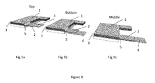
- a battery can be formed by an alternating stack of numerous cathodes and anodes. Each of these layers is divided by a separator. An ionic pathway is maintained by the presence, between each electrode, of an electrolyte. Each electrode 1 features a tab 2 protruding from its electrochemically active area and beyond the edge of the separator. These tabs 2 provide the first surface through which the stack 3 of lithium anodes will be welded to each other and joined to a contact lead 4. The tabs 2 are first folded and/or formed by pressing. A contact lead 4 is then positioned at the top ( Figure 1a ) or bottom ( Figure 1b ) of the stack 5 of tabs 2, or it may be positioned between any two lithium tabs 2 ( Figure 1c ) .
- the contact leads 4 may take a number of forms ( Figures 2a to 2e ) .
- the body 6 is composed of a conductive metal ribbon, typically nickel, copper, stainless steel or some composite conductor.
- the end portion 7 (the area to be welded) is typically perforated, meshed or punched.
- the end portion 7 may be an integral part of the metal ribbon 6, or it may be a separate piece welded to the ribbon 6. Where the end portion 7 is a separate piece welded to the ribbon 6, it may be made of a different metal to that of the ribbon 6.
- the contact may be linear, "T” or "L” shaped.
- the perforations may be rhombic, circular, square, rounded, polygonal or any other suitable shape.
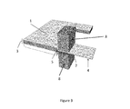
- the tabs 2 and the contact lead 4 are then positioned between the two weld fixtures 8 of an ultrasonic welder ( Figure 3 ) .
- the ultrasonic welder then simultaneously applies pressure and an ultrasonic wave to the weld area. This causes the numerous lithium layers 2 to fuse together to form a lithium-lithium weld. Further, the softened lithium percolates through the perforated or meshed area 7 of the contact lead 4.
- the contact lead 4 is hence joined to the lithium 2 as the mesh 7 is intimately surrounded by lithium.
- the high surface area contact between the mesh 7 of the contact lead 4 and the lithium electrode 1 produces a low resistance and a mechanically strong electrical contact. When the ultrasonic wave ceases and the pressure is released, the contact lead 4 will be joined to the lithium anodes 1.
- a linear nickel contact lead composed of 50 ⁇ m thick nickel ribbon, was used. The endmost 5mm of the contact lead was expanded to form a mesh.
- a stack of lithium contact tabs protruded from the battery. The lithium contact tabs were formed and trimmed to produce a flat welding area and to ensure that each of the tabs, regardless of its position, in the stack used the minimum quantity of lithium.
- the formed stack of lithium tabs was then positioned between the welding fixtures of an ultrasonic welder. The contact lead was then positioned on top of the stack of lithium tabs, such that the meshed region overlapped with the flat lithium welding zone.
- a "T" shaped contact lead was made by welding a piece of nickel ribbon (50 ⁇ m thick) to a piece of copper mesh.
- the mesh opening was approximately 200x700 ⁇ m, with a bar width of 100 ⁇ m.
- the mesh was thrice as long as the nickel ribbon was wide.
- the mesh was 5mm wide; the same as the welding zone.
- the mesh was positioned centrally to form the cross of the "T” and welded into position by an ultrasonic welder using the conditions given in Table 2, weld A.
- the contact lead was positioned between the welding fixtures of an ultrasonic welder such that the meshed region fell into the welding zone.
- An "L” shaped contact lead was manufactured by photochemical etching from a sheet of 100 ⁇ m thick stainless steel.
- the upright section of the “L” is continuous steel foil.
- the base of the “L” was etched with a mesh pattern.
- the mesh opening was 500x500 ⁇ m and the bar width was 100 ⁇ m.
- the base of the "L” was twice the width of the upright section.
- the width of the base section was 5mm, the same as the weld zone.
- the contact lead was positioned between the top face to the lowermost lithium contact tab and the bottom face of the remainder of the stack.
- the remainder of the stack of lithium contact tabs was pushed down onto the meshed region of the contact lead.
- the protruding meshed section of the contact lead was folded over the stack of contact tabs.
- the contact assembly was positioned between the welding fixtures of an ultrasonic welder such that the meshed regions fell into the welding zone.
Abstract
There is disclosed a method of connecting a lithium electrode to a contact lead in a rechargeable battery. The electrode comprises a sheet or foil of lithium or lithium alloy with a tab protruding from an edge of the sheet or foil. The contact lead comprises an electrically conductive lead with an end portion made of a second metal that does not alloy with lithium and has a plurality of through holes. The end portion of the contact lead and the tab of the electrode are positioned so that there is substantial overlap between the end portion and the tab. The metal of the tab is then caused, for example by pressing and welding, to penetrate through the through holes of the end portion so as to join the electrode to the contact lead. A combination electrode/contact lead assembly made by this method is also disclosed.
Description
- The present invention relates to the connection of a lithium or lithium alloy foil electrode or electrodes to a contact lead, so as to promote good electrical and mechanical contact therebetween.
- Primary and rechargeable batteries using metallic lithium as the active material for the negative electrode are known to have the highest energy per unit weight and per unit volume.
- For the purposes of the present application, the following definitions are to be considered:
- A negative electrode, or anode, is a lithium or lithium alloy foil component having a negative potential. A negative electrode typically features a current collector and a contact tab.
- A current collector is an electrically conductive metallic foil used to provide a path for electrons from the external electrical circuit to the electrochemically active portion of the battery. A current collector will typically feature a contact tab.
- A contact tab is a metal foil portion of the current collector, which does not take part in the electrochemical process. It may extend from an edge of the main body of the current collector and is used to form the mechanical base for a weld to a contact lead.
- A contact lead is a piece of electrically conductive metallic material used to form an electrical contact from the contact tab through a hermetically sealed battery container to the external electrical circuit. It is typically welded (in cells where metallic lithium is not used) or mechanically connected to the contact tab.
- The contact lead must be connected or joined to the lithium in such a manner that a low resistance electrical connection is formed. Further, the connection or join must be mechanically strong enough to last for the expected life of the battery.
- The current collectors in lithium primary batteries are typically composed of a metallic conductor other than lithium. The contact lead may be exposed to the electrolyte in an electrochemically active zone of the battery. This is not generally a problem in primary batteries; however it may cause problems in rechargeable (or secondary) batteries. In secondary batteries, lithium must be electrochemically deposited when the battery is recharged. In order to provide good reproducibility of performance, when the battery is repeatedly recharged, an excess of lithium is used so that lithium is only ever deposited onto lithium. If the contact lead or current collector is left exposed, then lithium will be plated onto a non-lithium substrate. This greatly increases the probability of unpredictable lithium deposition and hence poor cycling performance. This typically takes the form of active dendrite formation resulting in the quick degradation of the rechargeable lithium system. Examples of such failure mechanisms are described in
US5368958 , the full disclosure of which is incorporated into the present application by reference. - In a secondary battery with a lithium-based anode, the lithium is typically connected to the external circuit by one of two methods. Either a contact lead similar in design to that described for primary lithium batteries is used; as in
US7335440 , the full disclosure of which is incorporated into the present application by reference.US7335440 discloses the provision of a current collector in the form of a flat, solid piece of titanium, nickel, copper or an alloy of nickel or copper. The current collector is provided with a contact tab. A relatively long strip of alkali metal foil, having a width similar to the height of the current collector, is placed under the current collector and the two are pressed together. It is to be noted that, following assembly of the battery, the current collector (which is not made of an alkali metal) is immersed in electrolyte. Moreover,US7335440 states that this arrangement has problems in coiled, anode-limited cells of the type disclosed therein since there is a potential for a short circuit to be formed between the cathode material and the anode current collector when the thin layer of lithium has substantially depleted into the cathode in the outermost winding. - A variation of this method uses the metallic cell casing for the dual purpose of collecting current from the lithium, as in
US7108942 , the full disclosure of which is incorporated into the present application by reference. Additionally, the reverse face of the lithium electrode may be pressed or rolled against a thin metal current collector, as inUS5368958 , the full disclosure of which is incorporated into the present application by reference. The current collector can then be welded to a metal contact lead. However, if the current collector becomes exposed to the electrolyte, there is a risk that lithium will be plated onto the non-lithium current collector with the possible formation of dendrites that may short-circuit the battery. The metal current collector also adds unnecessary mass to the battery and reduces its specific energy. - In all of the examples described above, the contact of metallic lithium with the current collector is purely mechanical, which may be acceptable for primary batteries. However, for lithium metal rechargeable batteries such mechanical contact is not reliable. Indeed due to the reactive character of metallic lithium, corrosion layers may readily form on the interface of the mechanical connection between the lithium and the current collector. This may result in lower battery reliability as well as faster degradation in the capacity and cycle life of rechargeable lithium metal batteries.
- Viewed from a first aspect, there is provided a method of connecting at least one electrode to a contact lead, wherein the electrode comprises a sheet or foil of a first metal with a tab protruding from an edge of the sheet or foil, and wherein the contact lead comprises an electrically conductive lead with an end portion made of a second metal that does not alloy with the first metal and having a plurality of through holes, the method comprising the steps of:
- i) positioning the end portion of the contact lead and the tab of the at least one electrode so that there is substantial overlap between the end portion and the tab;
- ii) causing the metal of the tab to penetrate through the through holes of the end portion so as to join the at least one electrode to the contact lead.
- In step ii), the metal of the tab may be caused to penetrate through the through holes by pressing and welding, for example by way of ultrasonic welding, thermal contact welding, laser welding or induction welding. Advantageously, the welding is effected in such a way so as not to cause significant thermal deformation or changes in the main laminar sheet or foil of the at least one electrode, but to concentrate the applied energy in the locality of the tab.
- The end portion of the contact lead may be substantially flat or planar, or may take other shapes or configurations depending, for example, on the shape or configuration of any welding equipment that is used.
- In some embodiments, there may be provided a plurality of electrodes, each comprising a sheet or foil of the first metal with a tab protruding from each sheet in substantially the same location, so that the tabs of the stack of electrodes are substantially aligned when the electrodes are aligned with each other and arranged as an electrode stack.
- In these embodiments, the perforated end portion of the contact lead may be placed on top of the tabs of the electrode stack, underneath the tabs of the electrode stack, or at an intermediate position between the top and the bottom (i.e. with at least one tab above and at least one tab below). The tabs and the perforated end portion are then pressed together and the first metal (of the tabs) is caused to penetrate through the holes in the perforated planar end portion (made of the second metal) of the contact lead. Alternatively, the tabs of the electrode stack may be pressed together before the perforated end portion is placed on top of or underneath the compressed tabs and the penetration of step ii) is performed.
- In embodiments where there is provided a stack of electrodes, the pressing and welding step causes the tabs to join together physically as well as to penetrate into the through holes of the contact lead.
- Particularly preferred metals for the first metal are lithium and lithium alloys, since these tend to be useful as anode materials in secondary batteries, and are also soft and malleable, which allows a good connection to be made with the perforated end portion of the contact lead when the pressing and welding step is performed.
- The end portion of the contact lead may be perforated, punched or have a mesh-like or reticulated form. What is important is that when the first metal of the tabs is sufficiently malleable that it can pass through the through holes so as to cause the second metal of the end portion to become embedded in what is preferably a single phase of the first metal. This forms an intimate contact between the first and second metals, and thus between the contact lead and the electrodes.
- The greater the openness or surface area of the end portion of the contact lead, the better the electrical (and physical) connection between the contact lead and the electrodes. The openness of the end portion may be defined as the ratio of open area to the full surface area of the end portion. The openness of the end portion of the contact lead may be in the range of 5% to 95%.
- The electrically conductive lead of the contact lead may itself be generally planar, for example in the form of a ribbon, although other profiles may be useful. The electrically conductive lead may be made of the same metal as the second metal forming the end portion, or of a different metal.
- In this way, it is possible for form a reliable connection with a contact lead made of a metal other than the metal of the electrode. It will be understood that the contact lead, which will generally be exposed outside the casing of the battery, must be made of a metal that has good electrical conductivity but is not highly reactive when exposed to air or moisture. Suitable metals include nickel, copper, stainless steel or various alloys.
- Moreover, the metal of the contact lead, since it is connected only to the protruding tabs of the electrodes, is not directly exposed to electrolyte when the battery is assembled.
- A further advantage is that a good connection can be made to the at least one electrode without the electrode as a whole needing to be formed or disposed on a current collector made of a metal other than the first metal. In other words, the main part of the electrode that is exposed to the electrolyte consists solely of the first metal (e.g. lithium or a lithium alloy), with no need for a copper or nickel or other current collector that would add unnecessary weight and act as a substrate for the formation of dendrites during cycling.
- Moreover, it is important that the second metal (of the contact lead) is selected so that it does not form an alloy with the first metal (of the electrode). This is in order to avoid reduction of the amount of the first metal that is available to the electrochemical system of the battery. For example, lithium will form an alloy with aluminium, but not with nickel or copper.
- In certain embodiments, the electrode is configured as an anode, or negative electrode, for a battery. However, it will be appreciated that the method is applicable also to cathodes, or positive electrodes, where these are made of a metal that is suitable for pressing and welding to a perforated second metal as described.
- Viewed from a second aspect, there is provided, in combination, at least one electrode for a battery and a contact lead, wherein the electrode comprises a sheet or foil of a first metal with a tab protruding from an edge of the sheet or foil, and wherein the contact lead comprises an electrically conductive lead with an end portion made of a second metal that does not alloy with the first metal and having a plurality of through holes, wherein the first metal of the tab has been pressed and welded so as to penetrate through the through holes of the second metal end portion.
- Embodiments of the present invention seek to provide a negative electrode (anode) eliminating the need for the current collector, and a method of forming a reliable physical contact between different pieces of metallic lithium and the contact lead, thereby to promote good electrical contact between metallic lithium and the material of the contact lead.
- In preferred embodiments, an excess of metallic lithium is used such that at the end of the battery life there is a substantial amount of lithium metal which serves as the current collector for the negative electrode. The use of lithium as the current collector eliminates mechanical contact between metal lithium and another current collector material.
- In some embodiments, there may be provided a plurality of electrodes, each comprising a sheet or foil of the first metal with a tab protruding from each sheet in substantially the same location, so that the tabs of the stack of electrodes are substantially aligned when the electrodes are aligned with each other and arranged as an electrode stack.
- The lithium metal of the negative electrode in the region of the tabs may form a single phase connection from lithium electrode to lithium electrode in the electrode stack. Such connection is achieved by using pressing and welding as hereinbefore described.
- The contact lead, or at least the end portion thereof, may be thin (for example, with a thickness of 5 to 50µm), or may be thick (for example, with a thickness of 50 to 10,000µm).
- The contact lead may be substantially linear, or may have a 'T'-shaped or 'L'-shaped configuration.
- The end portion of the contact lead may be an integral part of the contact lead (in other words, formed from the same material as the rest of the contact lead and integral therewith), or may be a separate metal component, not necessarily of the same material as the rest of the contact lead, and welded thereto (for example by ultrasonic welding, thermal contact welding, laser welding, induction welding or other types of welding).
- Embodiments of the invention are further described hereinafter with reference to the accompanying drawings, in which:
-
FIGURES 1a to 1c shows a battery stack with anodes, cathodes and tabs, and three alternative positionings for a contact lead; -
FIGURES 2a to 2e shows possible designs for the contact lead; and -
FIGURE 3 shows the contact lead being ultrasonically welded to the tabs. - A battery can be formed by an alternating stack of numerous cathodes and anodes. Each of these layers is divided by a separator. An ionic pathway is maintained by the presence, between each electrode, of an electrolyte. Each
electrode 1 features atab 2 protruding from its electrochemically active area and beyond the edge of the separator. Thesetabs 2 provide the first surface through which thestack 3 of lithium anodes will be welded to each other and joined to acontact lead 4. Thetabs 2 are first folded and/or formed by pressing. Acontact lead 4 is then positioned at the top (Figure 1a ) or bottom (Figure 1b ) of thestack 5 oftabs 2, or it may be positioned between any two lithium tabs 2 (Figure 1c ). - The contact leads 4 may take a number of forms (
Figures 2a to 2e ). Thebody 6 is composed of a conductive metal ribbon, typically nickel, copper, stainless steel or some composite conductor. The end portion 7 (the area to be welded) is typically perforated, meshed or punched. Theend portion 7 may be an integral part of themetal ribbon 6, or it may be a separate piece welded to theribbon 6. Where theend portion 7 is a separate piece welded to theribbon 6, it may be made of a different metal to that of theribbon 6. The contact may be linear, "T" or "L" shaped. The perforations may be rhombic, circular, square, rounded, polygonal or any other suitable shape. - The
tabs 2 and thecontact lead 4 are then positioned between the twoweld fixtures 8 of an ultrasonic welder (Figure 3 ). The ultrasonic welder then simultaneously applies pressure and an ultrasonic wave to the weld area. This causes thenumerous lithium layers 2 to fuse together to form a lithium-lithium weld. Further, the softened lithium percolates through the perforated ormeshed area 7 of thecontact lead 4. Thecontact lead 4 is hence joined to thelithium 2 as themesh 7 is intimately surrounded by lithium. The high surface area contact between themesh 7 of thecontact lead 4 and thelithium electrode 1 produces a low resistance and a mechanically strong electrical contact. When the ultrasonic wave ceases and the pressure is released, thecontact lead 4 will be joined to thelithium anodes 1. - A linear nickel contact lead, composed of 50µm thick nickel ribbon, was used. The endmost 5mm of the contact lead was expanded to form a mesh. A battery with 60 lithium anodes, each of 78µm thickness, was assembled. A stack of lithium contact tabs protruded from the battery. The lithium contact tabs were formed and trimmed to produce a flat welding area and to ensure that each of the tabs, regardless of its position, in the stack used the minimum quantity of lithium. The formed stack of lithium tabs was then positioned between the welding fixtures of an ultrasonic welder. The contact lead was then positioned on top of the stack of lithium tabs, such that the meshed region overlapped with the flat lithium welding zone. The welding conditions listed in Table 1 were then entered into an AmTech 900B 40kHz ultrasonic welder. A single weld was then performed. Each of the 60 lithium layers were welded firmly to each other. A strong join was produced between the lithium and the contact lead. This join had been created by the softened lithium penetrating through the mesh of the contact lead.
Table 1 - The welder setting used in Example 1. Energy / J Amplitude / µm Trigger Pressure / Psi Pressure / Psi 180 5 20 20 - A "T" shaped contact lead was made by welding a piece of nickel ribbon (50µm thick) to a piece of copper mesh. The mesh opening was approximately 200x700µm, with a bar width of 100µm. The mesh was thrice as long as the nickel ribbon was wide. The mesh was 5mm wide; the same as the welding zone. The mesh was positioned centrally to form the cross of the "T" and welded into position by an ultrasonic welder using the conditions given in Table 2, weld A. The contact lead was positioned between the welding fixtures of an ultrasonic welder such that the meshed region fell into the welding zone.
- A battery with 20 lithium anodes, each of 78µm thickness, was assembled. A stack of lithium contact tabs protruded from the battery. The stack of lithium contact tabs was formed and trimmed to produce a flat welding area and to ensure that each of the contact tabs, regardless of its position, in the stack used the minimum quantity of lithium.
- The stack of lithium contact tabs was then positioned on top of the contact lead, between the welding fixtures of an ultrasonic welder. The copper mesh "arms" of the "T" shaped contact lead were then folded around the stack of lithium contact tabs. The welding conditions listed in Table 2, weld B were then entered into an AmTech 900B 40kHz ultrasonic welder. A single weld was then performed. Each of the 20 lithium layers were welded firmly to each other. A strong join was produced between the lithium and the contact lead. This join had been created by the softened lithium penetrating through the mesh of the contact lead.
Table 2 - The welder settings used in Example 2 Weld Energy / J Amplitude / µm Trigger Pressure / Psi Pressure / Psi A 70 80 80 5 B 10 5 20 20 - An "L" shaped contact lead was manufactured by photochemical etching from a sheet of 100µm thick stainless steel. The upright section of the "L" is continuous steel foil. The base of the "L" was etched with a mesh pattern. The mesh opening was 500x500µm and the bar width was 100µm. The base of the "L" was twice the width of the upright section. The width of the base section was 5mm, the same as the weld zone.
- A battery with 20 lithium anodes, each of 78µm thickness, was assembled. A stack of lithium contact tabs protruded from the battery. The contact lead was positioned between the top face to the lowermost lithium contact tab and the bottom face of the remainder of the stack. The remainder of the stack of lithium contact tabs was pushed down onto the meshed region of the contact lead. The protruding meshed section of the contact lead was folded over the stack of contact tabs. The contact assembly was positioned between the welding fixtures of an ultrasonic welder such that the meshed regions fell into the welding zone.
- The welding conditions listed in Table 3 were then entered into an AmTech 900B 40kHz ultrasonic welder. A single weld was then performed. Each of the 20 lithium layers were welded firmly to each other. A strong join was produced between the lithium and the contact lead. This join had been created by the softened lithium penetrating through the mesh of the contact lead.
Table 3 - The welder settings used in Example 3 Energy / J Amplitude / µm Trigger Pressure / Psi Pressure / Psi 40 5 20 20 - Throughout the description and claims of this specification, the words "comprise" and "contain" and variations of them mean "including but not limited to", and they are not intended to (and do not) exclude other moieties, additives, components, integers or steps. Throughout the description and claims of this specification, the singular encompasses the plural unless the context otherwise requires. In particular, where the indefinite article is used, the specification is to be understood as contemplating plurality as well as singularity, unless the context requires otherwise.
- Features, integers, characteristics, compounds, chemical moieties or groups described in conjunction with a particular aspect, embodiment or example of the invention are to be understood to be applicable to any other aspect, embodiment or example described herein unless incompatible therewith. All of the features disclosed in this specification (including any accompanying claims, abstract and drawings), and/or all of the steps of any method or process so disclosed, may be combined in any combination, except combinations where at least some of such features and/or steps are mutually exclusive. The invention is not restricted to the details of any foregoing embodiments. The invention extends to any novel one, or any novel combination, of the features disclosed in this specification (including any accompanying claims, abstract and drawings), or to any novel one, or any novel combination, of the steps of any method or process so disclosed.
- The reader's attention is directed to all papers and documents which are filed concurrently with or previous to this specification in connection with this application and which are open to public inspection with this specification, and the contents of all such papers and documents are incorporated herein by reference.
Claims (16)
- A method of connecting at least one electrode to a contact lead, wherein the electrode comprises a sheet or foil of a first metal with a tab protruding from an edge of the sheet or foil, and wherein the contact lead comprises an electrically conductive lead with an end portion made of a second metal that does not alloy with the first metal and having a plurality of through holes, the method comprising the steps of:i) positioning the end portion of the contact lead and the tab of the at least one electrode so that there is substantial overlap between the end portion and the tab;ii) causing the metal of the tab to penetrate through the through holes of the end portion so as to join the at least one electrode to the contact lead.
- A method according to claim 1, wherein, in step ii), the metal of the tab is caused to penetrate through the through holes by pressing and welding.
- A method according to claim 2, wherein the welding is ultrasonic welding.
- A method according to claim 2, wherein the welding is thermal contact welding, laser welding or induction welding.
- A method according to any one of claims 2 to 4, wherein the welding does not cause significant thermal deformation or changes in the laminar sheet or foil of the at least one electrode, but concentrates the applied energy in the locality of the tab.
- A method according to any one of the preceding claims, wherein there is provided a plurality of electrodes, each comprising a sheet or foil of the first metal with a tab protruding from each sheet in substantially the same location, so that the tabs of the stack of electrodes are substantially aligned when the electrodes are aligned with each other and arranged as an electrode stack.
- A method according to claim 6, wherein the perforated end portion of the contact lead is placed on top of the tabs of the electrode stack in step i).
- A method according to claim 6, wherein the perforated end portion of the contact lead is placed underneath the tabs of the electrode stack in step i).
- A method according to claim 6, wherein the perforated end portion of the contact lead is placed at an intermediate position between the top and the bottom of the electrode stack in step i).
- A method according to any one of claims 7 to 9, wherein the tabs and the perforated end portion are then pressed together and the first metal is caused to penetrate through the holes in the perforated end portion of the contact lead.
- A method according to claim 7 or 8, wherein the tabs of the electrode stack are pressed together before the perforated end portion is placed on top of or underneath the compressed tabs and the penetration of step ii) is performed.
- A method according to any preceding claim, wherein the end portion of the contact lead is an integral part of the contact lead.
- A method according to any one of claims 1 to 11, wherein the end portion of the contact lead is a separate metal component that is welded to the contact lead.
- A method according to any preceding claim, wherein the first metal is lithium or a lithium alloy.
- A method according to any preceding claim, wherein the second metal is selected from a group comprising: nickel, copper, a nickel or copper alloy that does not alloy with lithium, and stainless steel.
- In combination, at least one electrode for a battery and a contact lead, wherein the electrode comprises a sheet or foil of a first metal with a tab protruding from an edge of the sheet or foil, and wherein the contact lead comprises an electrically conductive lead with an end portion made of a second metal that does not alloy with the first metal and having a plurality of through holes, wherein the first metal of the tab has been pressed and/or welded so as to penetrate through the through holes of the second metal end portion.
Priority Applications (15)
| Application Number | Priority Date | Filing Date | Title |
|---|---|---|---|
| EP11193678.7A EP2605313A1 (en) | 2011-12-15 | 2011-12-15 | Connecting contact leads to lithium-based electrodes |
| RU2014128829/07A RU2598647C2 (en) | 2011-12-15 | 2012-07-11 | Connecting contact leads for lithium-based electrodes |
| PCT/GB2012/051633 WO2013088115A1 (en) | 2011-12-15 | 2012-07-11 | Connecting contact leads to lithium-based electrodes |
| CN201910113940.4A CN110010834B (en) | 2011-12-15 | 2012-07-11 | Connecting the contact lead to the lithium-based electrode |
| EP12738163.0A EP2791998B1 (en) | 2011-12-15 | 2012-07-11 | Connecting contact leads to lithium-based electrodes |
| ES12738163.0T ES2613543T3 (en) | 2011-12-15 | 2012-07-11 | Connection of contacts to lithium-based electrodes |
| KR1020147016102A KR102048596B1 (en) | 2011-12-15 | 2012-07-11 | Connecting contact leads to lithium-based electrodes |
| JP2014546626A JP6285366B2 (en) | 2011-12-15 | 2012-07-11 | Connecting contact leads to lithium-based electrodes |
| US14/365,835 US20150056506A1 (en) | 2011-12-15 | 2012-07-11 | Connecting contact leads to lithiumbased electrodes |
| CN201280061861.XA CN103999261A (en) | 2011-12-15 | 2012-07-11 | Connecting contact leads to lithium-based electrodes |
| CA2852246A CA2852246C (en) | 2011-12-15 | 2012-07-11 | Connecting contact leads to lithium-based electrodes |
| PL12738163T PL2791998T3 (en) | 2011-12-15 | 2012-07-11 | Connecting contact leads to lithium-based electrodes |
| GB1214595.9A GB2495581B (en) | 2011-12-15 | 2012-08-16 | Connecting contact leads to lithium-based electrodes |
| HK13105013.7A HK1178321A1 (en) | 2011-12-15 | 2013-04-25 | Connecting contact leads to lithium-based electrodes |
| US18/311,486 US20230290927A1 (en) | 2011-12-15 | 2023-05-05 | Connecting contact leads to lithium-based electrodes |
Applications Claiming Priority (1)
| Application Number | Priority Date | Filing Date | Title |
|---|---|---|---|
| EP11193678.7A EP2605313A1 (en) | 2011-12-15 | 2011-12-15 | Connecting contact leads to lithium-based electrodes |
Publications (1)
| Publication Number | Publication Date |
|---|---|
| EP2605313A1 true EP2605313A1 (en) | 2013-06-19 |
Family
ID=45406458
Family Applications (2)
| Application Number | Title | Priority Date | Filing Date |
|---|---|---|---|
| EP11193678.7A Withdrawn EP2605313A1 (en) | 2011-12-15 | 2011-12-15 | Connecting contact leads to lithium-based electrodes |
| EP12738163.0A Active EP2791998B1 (en) | 2011-12-15 | 2012-07-11 | Connecting contact leads to lithium-based electrodes |
Family Applications After (1)
| Application Number | Title | Priority Date | Filing Date |
|---|---|---|---|
| EP12738163.0A Active EP2791998B1 (en) | 2011-12-15 | 2012-07-11 | Connecting contact leads to lithium-based electrodes |
Country Status (10)
| Country | Link |
|---|---|
| US (2) | US20150056506A1 (en) |
| EP (2) | EP2605313A1 (en) |
| JP (1) | JP6285366B2 (en) |
| KR (1) | KR102048596B1 (en) |
| CN (2) | CN110010834B (en) |
| CA (1) | CA2852246C (en) |
| ES (1) | ES2613543T3 (en) |
| PL (1) | PL2791998T3 (en) |
| RU (1) | RU2598647C2 (en) |
| WO (1) | WO2013088115A1 (en) |
Cited By (7)
| Publication number | Priority date | Publication date | Assignee | Title |
|---|---|---|---|---|
| GB2562950B (en) * | 2016-02-11 | 2021-03-03 | Noco Co | Battery connector device for a battery jump starting device |
| US11447023B2 (en) | 2014-07-03 | 2022-09-20 | The Noco Company | Portable vehicle battery jump start apparatus with safety protection and jumper cable device thereof |
| US11458851B2 (en) | 2014-07-03 | 2022-10-04 | The Noco Company | Jump starting apparatus |
| WO2022235159A1 (en) * | 2021-05-04 | 2022-11-10 | Leydenjar Technologies B.V. | Electrode assembly for a battery having an ultrasonic weld, method for manufacture and use of the assembly |
| NL2028136B1 (en) * | 2021-05-04 | 2022-11-10 | Leydenjar Tech B V | Method for joining an electrode tab to a current collector using ultrasonic welding, an electrode assembly for a battery, and use of the assembly |
| US11611222B2 (en) | 2017-12-14 | 2023-03-21 | The Noco Company | Portable vehicle battery jump starter with air pump |
| US11788500B2 (en) | 2016-02-11 | 2023-10-17 | The Noco Company | Battery device for a battery jump starting device |
Families Citing this family (14)
| Publication number | Priority date | Publication date | Assignee | Title |
|---|---|---|---|---|
| CN104396050B (en) * | 2012-06-28 | 2016-08-17 | 丰田自动车株式会社 | The manufacture method of battery and battery |
| US9941506B2 (en) * | 2014-02-21 | 2018-04-10 | Semiconductor Energy Laboratory Co., Ltd. | Current collector, secondary battery, electronic device, and manufacturing method thereof |
| KR102207904B1 (en) * | 2016-07-27 | 2021-01-25 | 삼성에스디아이 주식회사 | Rechargeable battery |
| KR102629053B1 (en) | 2016-08-08 | 2024-01-23 | 삼성에스디아이 주식회사 | Rechargeable battery having current collector |
| GB2555408B (en) * | 2016-10-25 | 2019-03-27 | Oxis Energy Ltd | Interconnection |
| KR102044404B1 (en) * | 2017-03-16 | 2019-11-14 | 주식회사 리베스트 | Flexible battery assembly having strengthening tab joint structure between electrode tab and electrode lead |
| JP6669122B2 (en) * | 2017-04-07 | 2020-03-18 | トヨタ自動車株式会社 | Stacked battery |
| DE102017215962A1 (en) | 2017-09-11 | 2019-03-14 | Robert Bosch Gmbh | Method for producing an electrode unit for a battery cell and battery cell |
| KR102567963B1 (en) * | 2018-07-18 | 2023-08-16 | 주식회사 엘지에너지솔루션 | Method for bonding a negative electrode tap of lithium metal battery, a negative electrode for a lithium metal battery preparing by applying the same and a lithium metal battery including the same |
| CN111375882A (en) * | 2018-12-28 | 2020-07-07 | 中天储能科技有限公司 | Tab welding method and battery prepared by using same |
| KR20220018744A (en) | 2020-08-07 | 2022-02-15 | 주식회사 엘지에너지솔루션 | Support Member for Welding and Welding Method Using the Same |
| CN113097656B (en) * | 2021-05-10 | 2023-04-25 | 厦门海辰储能科技股份有限公司 | Pole piece, battery core assembly and battery |
| KR20230099155A (en) | 2021-12-27 | 2023-07-04 | 주식회사 엘지에너지솔루션 | Divice for pressing a bonding unit of electrode tab and electrode lead |
| CN115189099A (en) * | 2022-07-27 | 2022-10-14 | 肇庆小鹏汽车有限公司 | Battery tab and battery |
Citations (7)
| Publication number | Priority date | Publication date | Assignee | Title |
|---|---|---|---|---|
| GB2200068A (en) * | 1986-12-24 | 1988-07-27 | Sylva Ind Limited | Ultrasonic welding technique, particularly for welding contact tab to battery electrode |
| US5368958A (en) | 1992-08-20 | 1994-11-29 | Advanced Energy Technologies Incorporated | Lithium anode with conductive for and anode tab for rechargeable lithium battery |
| EP0924783A1 (en) * | 1997-12-22 | 1999-06-23 | Japan Storage Battery Company Limited | Porous pasted electrode, cell using the same and process for producing electrode |
| US7108942B1 (en) | 2003-03-27 | 2006-09-19 | Wilson Greatbatch Technologies, Inc. | Efficient electrode assembly design for cells with alkali metal anodes |
| US7335440B2 (en) | 2003-09-12 | 2008-02-26 | Medtronic, Inc. | Lithium-limited anode subassembly with solid anode current collector and spacer |
| EP2026402A1 (en) * | 2007-07-11 | 2009-02-18 | Nissan Motor Co., Ltd. | Laminate type battery |
| JP2011108469A (en) * | 2009-11-17 | 2011-06-02 | Toyota Motor Corp | Current collector and its manufacturing method |
Family Cites Families (26)
| Publication number | Priority date | Publication date | Assignee | Title |
|---|---|---|---|---|
| FR2055865A5 (en) * | 1969-08-01 | 1971-05-14 | Accumulateurs Fixes | |
| JPS57157462A (en) * | 1981-03-23 | 1982-09-29 | Fuji Elelctrochem Co Ltd | Manufacture of non-aqueous electrolyte battery |
| JPS5873966A (en) * | 1981-10-26 | 1983-05-04 | Fuji Elelctrochem Co Ltd | Manufacture of nonaqueous electrolyte battery |
| US6056185A (en) * | 1998-03-18 | 2000-05-02 | Ga-Tek Inc. | Method of connecting batteries to electronic circuits |
| JP4016506B2 (en) * | 1998-10-16 | 2007-12-05 | ソニー株式会社 | Solid electrolyte battery |
| JP4797219B2 (en) * | 1999-12-09 | 2011-10-19 | パナソニック株式会社 | Battery lead wire connection device |
| JP4644899B2 (en) * | 2000-02-23 | 2011-03-09 | ソニー株式会社 | Electrode and battery, and manufacturing method thereof |
| US6641027B2 (en) * | 2001-12-18 | 2003-11-04 | Ngk Spark Plug Co., Ltd. | Method of connecting electric leads to battery tabs |
| CA2384215A1 (en) * | 2002-04-30 | 2003-10-30 | Richard Laliberte | Electrochemical bundle and method for making same |
| KR100477969B1 (en) * | 2002-10-25 | 2005-03-23 | 삼성에스디아이 주식회사 | Negative electrode for lithium battery and lithium battery comprising same |
| JP4494731B2 (en) * | 2003-06-13 | 2010-06-30 | 三菱重工業株式会社 | Secondary battery and method for manufacturing secondary battery |
| US7646171B2 (en) * | 2004-01-06 | 2010-01-12 | Sion Power Corporation | Methods of charging lithium sulfur cells |
| JP2006173079A (en) * | 2004-11-18 | 2006-06-29 | Sony Corp | Battery |
| KR100888284B1 (en) * | 2006-07-24 | 2009-03-10 | 주식회사 엘지화학 | Electrode Assembly Having Tap-Lead Joint Portion of Minimized Resistance Difference between Electrodes and Electrochemical Cell Containing the Same |
| US20080026293A1 (en) * | 2006-07-26 | 2008-01-31 | Eveready Battery Company, Inc. | Lithium-iron disulfide cylindrical cell with modified positive electrode |
| JP5114036B2 (en) * | 2006-09-08 | 2013-01-09 | Necエナジーデバイス株式会社 | Manufacturing method of stacked battery |
| JP4337875B2 (en) * | 2006-12-29 | 2009-09-30 | ソニー株式会社 | Positive electrode mixture, non-aqueous electrolyte secondary battery, and manufacturing method thereof |
| KR101156954B1 (en) * | 2007-06-05 | 2012-06-20 | 주식회사 엘지화학 | Electrode Assembly with Excellent Weldability between Electrode Lead and Electrode Tabs and Secondary Battery Comprising the Same |
| JP5111991B2 (en) * | 2007-09-28 | 2013-01-09 | 株式会社東芝 | battery |
| US20100190055A1 (en) * | 2009-01-29 | 2010-07-29 | Gm Global Technology Operations, Inc. | Battery cell connection method and apparatus |
| RU2398314C1 (en) * | 2009-03-11 | 2010-08-27 | Общество с ограниченной ответственностью "Транспорт" | Multi-purpose storage battery |
| KR101106428B1 (en) * | 2009-12-01 | 2012-01-18 | 삼성에스디아이 주식회사 | Secondary battery |
| JP2011192574A (en) * | 2010-03-16 | 2011-09-29 | Panasonic Corp | Lithium primary battery |
| JP4995297B2 (en) * | 2010-03-26 | 2012-08-08 | 三菱重工業株式会社 | Battery and ultrasonic welding system used for manufacturing the battery |
| US9620768B2 (en) * | 2012-05-22 | 2017-04-11 | Sanyo Electric Co., Ltd. | Negative electrode for lithium secondary batteries, lithium secondary battery, and method for producing the negative electrode for lithium secondary batteries |
| WO2017111988A1 (en) * | 2015-12-22 | 2017-06-29 | Intel IP Corporation | Multiplexing of control signaling and data transmission in enhanced frame structures |
-
2011
- 2011-12-15 EP EP11193678.7A patent/EP2605313A1/en not_active Withdrawn
-
2012
- 2012-07-11 EP EP12738163.0A patent/EP2791998B1/en active Active
- 2012-07-11 WO PCT/GB2012/051633 patent/WO2013088115A1/en active Application Filing
- 2012-07-11 JP JP2014546626A patent/JP6285366B2/en active Active
- 2012-07-11 US US14/365,835 patent/US20150056506A1/en not_active Abandoned
- 2012-07-11 PL PL12738163T patent/PL2791998T3/en unknown
- 2012-07-11 CA CA2852246A patent/CA2852246C/en active Active
- 2012-07-11 KR KR1020147016102A patent/KR102048596B1/en active IP Right Grant
- 2012-07-11 CN CN201910113940.4A patent/CN110010834B/en active Active
- 2012-07-11 ES ES12738163.0T patent/ES2613543T3/en active Active
- 2012-07-11 CN CN201280061861.XA patent/CN103999261A/en active Pending
- 2012-07-11 RU RU2014128829/07A patent/RU2598647C2/en active
-
2023
- 2023-05-05 US US18/311,486 patent/US20230290927A1/en active Pending
Patent Citations (7)
| Publication number | Priority date | Publication date | Assignee | Title |
|---|---|---|---|---|
| GB2200068A (en) * | 1986-12-24 | 1988-07-27 | Sylva Ind Limited | Ultrasonic welding technique, particularly for welding contact tab to battery electrode |
| US5368958A (en) | 1992-08-20 | 1994-11-29 | Advanced Energy Technologies Incorporated | Lithium anode with conductive for and anode tab for rechargeable lithium battery |
| EP0924783A1 (en) * | 1997-12-22 | 1999-06-23 | Japan Storage Battery Company Limited | Porous pasted electrode, cell using the same and process for producing electrode |
| US7108942B1 (en) | 2003-03-27 | 2006-09-19 | Wilson Greatbatch Technologies, Inc. | Efficient electrode assembly design for cells with alkali metal anodes |
| US7335440B2 (en) | 2003-09-12 | 2008-02-26 | Medtronic, Inc. | Lithium-limited anode subassembly with solid anode current collector and spacer |
| EP2026402A1 (en) * | 2007-07-11 | 2009-02-18 | Nissan Motor Co., Ltd. | Laminate type battery |
| JP2011108469A (en) * | 2009-11-17 | 2011-06-02 | Toyota Motor Corp | Current collector and its manufacturing method |
Cited By (12)
| Publication number | Priority date | Publication date | Assignee | Title |
|---|---|---|---|---|
| US11447023B2 (en) | 2014-07-03 | 2022-09-20 | The Noco Company | Portable vehicle battery jump start apparatus with safety protection and jumper cable device thereof |
| US11458851B2 (en) | 2014-07-03 | 2022-10-04 | The Noco Company | Jump starting apparatus |
| US11584243B2 (en) | 2014-07-03 | 2023-02-21 | The Noco Company | Jump starting device with USB |
| US11667203B2 (en) | 2014-07-03 | 2023-06-06 | The Noco Company | Portable vehicle battery jump start apparatus with safety protection |
| US11766945B2 (en) | 2014-07-03 | 2023-09-26 | The Noco Company | Jump starting apparatus |
| GB2562950B (en) * | 2016-02-11 | 2021-03-03 | Noco Co | Battery connector device for a battery jump starting device |
| US11788500B2 (en) | 2016-02-11 | 2023-10-17 | The Noco Company | Battery device for a battery jump starting device |
| US11611222B2 (en) | 2017-12-14 | 2023-03-21 | The Noco Company | Portable vehicle battery jump starter with air pump |
| WO2022235159A1 (en) * | 2021-05-04 | 2022-11-10 | Leydenjar Technologies B.V. | Electrode assembly for a battery having an ultrasonic weld, method for manufacture and use of the assembly |
| NL2028136B1 (en) * | 2021-05-04 | 2022-11-10 | Leydenjar Tech B V | Method for joining an electrode tab to a current collector using ultrasonic welding, an electrode assembly for a battery, and use of the assembly |
| NL2028135B1 (en) * | 2021-05-04 | 2022-11-10 | Leydenjar Tech B V | Electrode assembly for a battery having an ultrasonic weld, method for manufacture and use of the assembly |
| WO2022235158A1 (en) * | 2021-05-04 | 2022-11-10 | Leydenjar Technologies B.V. | Method for joining an electrode tab to a current collector using ultrasonic welding, an electrode assembly for a battery, and use of the assembly |
Also Published As
| Publication number | Publication date |
|---|---|
| JP6285366B2 (en) | 2018-02-28 |
| KR20140113646A (en) | 2014-09-24 |
| CN103999261A (en) | 2014-08-20 |
| KR102048596B1 (en) | 2019-11-25 |
| JP2015505131A (en) | 2015-02-16 |
| CN110010834B (en) | 2022-04-08 |
| PL2791998T3 (en) | 2017-06-30 |
| EP2791998A1 (en) | 2014-10-22 |
| WO2013088115A1 (en) | 2013-06-20 |
| CA2852246C (en) | 2019-01-22 |
| US20230290927A1 (en) | 2023-09-14 |
| EP2791998B1 (en) | 2017-01-11 |
| RU2598647C2 (en) | 2016-09-27 |
| CA2852246A1 (en) | 2013-06-20 |
| CN110010834A (en) | 2019-07-12 |
| RU2014128829A (en) | 2016-02-10 |
| US20150056506A1 (en) | 2015-02-26 |
| ES2613543T3 (en) | 2017-05-24 |
Similar Documents
| Publication | Publication Date | Title |
|---|---|---|
| EP2605313A1 (en) | Connecting contact leads to lithium-based electrodes | |
| US20240088396A1 (en) | Secondary battery and electrode plate | |
| WO2008010656A1 (en) | Electrode assembly having stable lead-tap joint and electrochemical cell containing them | |
| US20050233209A1 (en) | Electrical contact for current collectors of electrochemical cells and method therefor | |
| KR102041131B1 (en) | Cylindrical Battery Cell Having Can of Dissimilar Metals | |
| EP2946868B1 (en) | Method of manufacturing a sealed battery | |
| JP2005310577A (en) | Coin type secondary battery | |
| US10181594B2 (en) | Method for manufacturing stacked metal foil, method for manufacturing sealed cell including said method, and sealed cell | |
| JP4250528B2 (en) | Electrochemical cell with terminal | |
| EP2584630B1 (en) | Method of reducing tabbing volume required for the external connections of an electrode assembly | |
| US20040185332A1 (en) | Tabs for electrochemical cells | |
| JP2000077054A (en) | Battery and its manufacture | |
| CN217933932U (en) | Battery cell structure and battery | |
| JP4498772B2 (en) | Alkaline storage battery and its manufacturing method | |
| KR20140022531A (en) | Electrode assembly and fabricating method of electrochemical cell containing the electrode assembly, electrochemical cell | |
| KR101849757B1 (en) | Secondary Battery Including an Electrode Lead Made of a Combination of Metal Layers Having Different Resistance Values | |
| JPS58119154A (en) | Alkaline storage battery | |
| JP2000021384A (en) | Battery | |
| KR20130134238A (en) | Secondary battery and method for fabricating the same | |
| GB2495581A (en) | Connecting contact leads to lithium-based electrodes | |
| JP2020095849A (en) | battery | |
| JPH11260355A (en) | Manufacture of electrochemical element | |
| JP5697472B2 (en) | Electrochemical element | |
| CN214848699U (en) | Bipolar current-collecting battery | |
| EP4318682A1 (en) | Current collector for electrode |
Legal Events
| Date | Code | Title | Description |
|---|---|---|---|
| PUAI | Public reference made under article 153(3) epc to a published international application that has entered the european phase |
Free format text: ORIGINAL CODE: 0009012 |
|
| AK | Designated contracting states |
Kind code of ref document: A1 Designated state(s): AL AT BE BG CH CY CZ DE DK EE ES FI FR GB GR HR HU IE IS IT LI LT LU LV MC MK MT NL NO PL PT RO RS SE SI SK SM TR |
|
| AX | Request for extension of the european patent |
Extension state: BA ME |
|
| STAA | Information on the status of an ep patent application or granted ep patent |
Free format text: STATUS: THE APPLICATION IS DEEMED TO BE WITHDRAWN |
|
| 18D | Application deemed to be withdrawn |
Effective date: 20131220 |