EP4354482B1 - Umwandelbarer elektrischer schalter - Google Patents
Umwandelbarer elektrischer schalter Download PDFInfo
- Publication number
- EP4354482B1 EP4354482B1 EP22382955.7A EP22382955A EP4354482B1 EP 4354482 B1 EP4354482 B1 EP 4354482B1 EP 22382955 A EP22382955 A EP 22382955A EP 4354482 B1 EP4354482 B1 EP 4354482B1
- Authority
- EP
- European Patent Office
- Prior art keywords
- activation element
- activation
- rocker
- base
- electrical switch
- Prior art date
- Legal status (The legal status is an assumption and is not a legal conclusion. Google has not performed a legal analysis and makes no representation as to the accuracy of the status listed.)
- Active
Links
Images

Classifications
-
- H—ELECTRICITY
- H01—ELECTRIC ELEMENTS
- H01H—ELECTRIC SWITCHES; RELAYS; SELECTORS; EMERGENCY PROTECTIVE DEVICES
- H01H11/00—Apparatus or processes specially adapted for the manufacture of electric switches
- H01H11/0006—Apparatus or processes specially adapted for the manufacture of electric switches for converting electric switches
-
- H—ELECTRICITY
- H01—ELECTRIC ELEMENTS
- H01H—ELECTRIC SWITCHES; RELAYS; SELECTORS; EMERGENCY PROTECTIVE DEVICES
- H01H13/00—Switches having rectilinearly-movable operating part or parts adapted for pushing or pulling in one direction only, e.g. push-button switch
- H01H13/02—Details
- H01H13/12—Movable parts; Contacts mounted thereon
- H01H13/20—Driving mechanisms
-
- H—ELECTRICITY
- H01—ELECTRIC ELEMENTS
- H01H—ELECTRIC SWITCHES; RELAYS; SELECTORS; EMERGENCY PROTECTIVE DEVICES
- H01H23/00—Tumbler or rocker switches, i.e. switches characterised by being operated by rocking an operating member in the form of a rocker button
- H01H23/02—Details
- H01H23/12—Movable parts; Contacts mounted thereon
- H01H23/14—Tumblers
- H01H23/146—Tumblers having a generally tubular or conical elongated shape, e.g. dolly
-
- H—ELECTRICITY
- H01—ELECTRIC ELEMENTS
- H01H—ELECTRIC SWITCHES; RELAYS; SELECTORS; EMERGENCY PROTECTIVE DEVICES
- H01H23/00—Tumbler or rocker switches, i.e. switches characterised by being operated by rocking an operating member in the form of a rocker button
- H01H23/28—Tumbler or rocker switches, i.e. switches characterised by being operated by rocking an operating member in the form of a rocker button with three operating positions
- H01H23/30—Tumbler or rocker switches, i.e. switches characterised by being operated by rocking an operating member in the form of a rocker button with three operating positions with stable centre positions and one or both end positions unstable
-
- H—ELECTRICITY
- H01—ELECTRIC ELEMENTS
- H01H—ELECTRIC SWITCHES; RELAYS; SELECTORS; EMERGENCY PROTECTIVE DEVICES
- H01H11/00—Apparatus or processes specially adapted for the manufacture of electric switches
- H01H11/0006—Apparatus or processes specially adapted for the manufacture of electric switches for converting electric switches
- H01H2011/0043—Apparatus or processes specially adapted for the manufacture of electric switches for converting electric switches for modifying the number or type of operating positions, e.g. momentary and stable
-
- H—ELECTRICITY
- H01—ELECTRIC ELEMENTS
- H01H—ELECTRIC SWITCHES; RELAYS; SELECTORS; EMERGENCY PROTECTIVE DEVICES
- H01H23/00—Tumbler or rocker switches, i.e. switches characterised by being operated by rocking an operating member in the form of a rocker button
- H01H23/02—Details
- H01H23/12—Movable parts; Contacts mounted thereon
- H01H23/16—Driving mechanisms
- H01H23/20—Driving mechanisms having snap action
- H01H23/205—Driving mechanisms having snap action using a compression spring between tumbler and an articulated contact plate
Definitions
- the present invention relates to electrical switches or commutators, and more specifically to those comprising an actuating rocker assembled on the base body of the switch which can be actuated between two stable connection and disconnection positions, being convertible into a push-button type switch with a single stable position by means of the action of a spring.
- a push-button is understood to be momentary switches, wherein electrical connection takes place while actuation is taking place and returns to the disconnection position when the actuation ends. Furthermore, said momentary switches can be normally open or normally closed.
- European Patent document EP2924702 discloses a switch of this type, in which the rocker has a hollow head in which a force transmission element is fitted, such that when the transmission element is coupled, the spring is activated so that the rocker acts like a push-button, and when the transmission element is uncoupled, it works as an ON-OFF switch with two opposed stable positions.
- this solution has a number of drawbacks such as the fact that the connection of the force transmission element is performed by pressure, for example, by clipping, such that it hinders activation by the user who must apply force to snap-fit the pressure element into the hollow head of the rocker, where correct coupling may not be established if insufficient force is applied, or the part making up the transmission element may break when force is applied with too much pressure. Furthermore, if it is configured so that the pressure to be exerted is very small, the force of the spring may cause the uncoupling of the clipping between the head of the rocker and the force transmission element.
- the present invention provides a convertible electrical switch with an actuating rocker assembled on a base of a switch body such that it can swivel between two stable switch connection and disconnection positions, and with an actuating element connectable to the actuating rocker pushing the actuating rocker to a single stable position, when the activation element and the rocker are connected in an activation position, by means of the action of a spring coupled to the activation element, converting the switch into a push-button.
- the activation element in which the activation element is arranged such that it is slidingly assembled in a guided manner through a window of the actuating rocker with a geometry in correspondence with the external geometry of the activation element such that in the inactive position the activation element goes through the window without pushing the rocker, whereas in the activation position the activation element is configured to push the rocker by means of at least one projection after establishing a rotation of said activation element, such that the projection contacts the rocker, being moved together with the activation element by means of the action of the spring without both elements being attached.
- the force of the spring pushes the activation element which, by means of a rectilinear movement in the actuation direction of the spring, in turn pushes the rocker along its curvilinear movement, with there being a relative movement between the rocker and the activation element throughout of the movement.
- the activation element remains freely assembled inside the switch without having to be coupled to any part of the switch, but is positioned inside the switch with a freedom of movement (in the actuation direction of the spring) established by the guidance provided by the window of the rocker, thus eliminating couplings or attachments that are susceptible to breakage or malfunction.
- the activation of the spring for converting the switch to a push-button is facilitated, given that simply by rotating the activation element, it is possible to connect the activation element with the rocker and push the rocker with the force of the spring, as a result of the contact of the protrusion of the activation element. In this case, it is not necessary to adjust the force of the spring for the coupling, since the rotation ensures contact between the rocker and the activation element without the risk of their attachment, resulting from the push of the spring, being disconnected. Likewise, transition to the inactive position is facilitated simply by rotating in the opposite direction to the initial inactive position in which the spring does not exert any force on the rocker.
- the geometry of the activation element will be cylindrical, this configuration being the optimal configuration for establishing activation by rotation.
- the convertible electrical switch comprises a bowl-shaped opening which establishes an inner guidance with respect to a shaft projecting from the base by means of the sliding between respective surfaces. Therefore, the activation element, in addition to being guided externally by the window of the rocker, is internally guided by the shaft projecting from the base to be inserted into the activation element.
- the activation element remains slidingly assembled inside the switch, with the movement thereof being allowed only in the direction of the force of the spring, without the need to be fixed to any element of the switch, therefore avoiding a coupling that is susceptible to breakage, and providing more robustness in the assembly.
- the spring sits in contact with the base shaft along same. This configuration retains the spring between the base and the activation element, preventing it from coming out of its seat, and ensuring that the force of the spring effort is applied in only one direction.
- the activation element comprises in the opening an activation element shaft on which the spring sits in contact with said activation element shaft along same. This configuration more effectively secures the spring in its seat, preventing it from moving laterally, and ensuring that the force is applied only in one activation direction.
- the base comprises a groove configured for guiding the activation element.
- This groove comprises a geometry in correspondence with the geometry of the activation element, preferably cylindrical, such that there is established an annular groove in which the lower part of the actuation element penetrates, being guided in the lower portion on its outer surface by the wall of said groove, and internally by the base shaft.
- the activation element comprises on its periphery at least one flange complementary to at least one clipping tooth of the base configured for establishing a movement stop for stopping the movement of the activation element once the clipped assembly of the activation element in the base has been established.
- the activation element in addition to being retained by the established guide or guides, comprises a movement stop which prevents it from coming out of its housing.
- Said flange can be a continuous perimeter rib such that said stop acts during the rotation of the activation element.
- the activation element comprises at least one stop rib which determines a rotation stop for the activation element up to the activation position upon contacting the clipping tooth of the base. In this way it is ensured that the active position has been reached, and the activation element correctly pushes the rocker.
- This rib can also serve as an indicator so that the angular position of the activation element can be identified by viewing said rib.
- the actuating rocker comprises a retaining recess configured for the fitting of the projection of the activation element in the activation position. Simply by the force of the spring upon reaching the activation position, the projection of the activation element will move up until it fits into the recess in the rocker.
- the activation element comprises an activation groove accessible through the window of the actuating rocker by means of a tool such as a screwdriver, which makes it easier to access the activation element and to establish the necessary rotation.
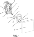
- the switch comprises a body (5) with a base (2) on which the actuating rocker (1) is assembled such that it can swivel between two stable switch connection and disconnection positions, with a decorative plate (6) which facilitates activation by a user being assembled on said rocker (1).
- the object of the invention is to convert the switch with two stable positions into a switch with a push-button function which, by means of the action of a spring (4), urges the rocker (1) to a single momentary stable position as long as the actuation on the plate (6) is maintained.
- the switch comprises an activation element (3) which is arranged such that it is slidingly assembled in a guided manner between the rocker (1) and the base (2), and serves as a seat for a spring (4) which performs a pushing function so as to convert the switch with two stable positions into a push-button.
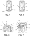
- the rocker (1) comprises a window (1.1) the geometry of which corresponds with the geometry of the activation element (3) which, in the inactive state, as can be seen in Figures 2 and 4 , the activation element (3) is free without interfering with the rocker (1) when it is pressed, such that the activation element (3) remains stationary and goes through the window (1.1) of the rocker (1), with the spring (4) remaining in its extended position.
- the activation element (3) is in the shape of a cylinder.
- the activation element (3) preferably comprises two projections (3.1) arranged preferably in diametrically opposite positions, such that when a manual rotation of said activation element (3) is established by the user, as can be seen in Figure 3 , the activation element (3), by means of the action of the spring (4), connects with the rocker (1) in an activation position. Therefore, the activation element (3) moves together with the rocker (1) without both elements being attached, pushing same with the projections (3.1) by means of the action of the spring (4), such that in said activation position the rocker (1) is always urged to a single stable position, being converted into a push-button.
- Figure 5 shows how the projections (3.1) no longer coincide with the geometry of the window (1.1) as they are in contact with the rocker (1).
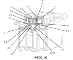
- the base (2) comprises a base shaft (2.1) projecting from said base (2) such that it is inserted into an inner bowl-shaped opening (3.2) of the activation element (3).
- the shaft (2.1) preferably has a cylindrical configuration such that an inner sliding guidance is established between both elements which, together with the sliding guidance between the outer surface of the activation element (3) and the window (1.1) of the rocker, ensures the positioning of the activation element (3) such that it is slidingly assembled inside the switch.
- this inner guidance is established between the outer surface of the base shaft (2.1) and the inner surface of the opening (3.2) of the activation element.
- the spring (4) will only remain under compression in its activation position before bringing the rocker to the stable position, such that the service life of the switch is prolonged by not maintaining the spring (4) in its forced compression position.
- the base (2) comprises an annular groove (2.2) which, as seen in Figures 1 to 3 , surrounds the shaft (2.1) of the base (2).
- This groove (2.2) allows the activation element (3) to be inserted therein and to not come out of its path in the actuation direction of the spring (4) when the activation element is in the activation position, being guided internally by the shaft (2.1) of the base (2) and externally by the walls of the groove (2.2), since in this position it does not have the guidance of the window (1.1) of the rocker (1).
- the activation element (3) comprises on its periphery at least one flange (3.4), preferably two flanges (3.4) facing one another (not shown), and even more preferably a flange (3.4) in the form of a continuous perimeter rib ( Figure 7 ) which, in a manner complementary to at least one clipping tooth (2.3) of the base (2), and preferably two clipping teeth (2.3) facing one another in diametrically opposite positions, establishes a clipped assembly of the activation element (3) which defines a movement stop for stopping the movement of the activation element in the actuation direction of the spring.
- said clipping teeth (2.3) are formed by respective legs projecting from the base (2).
- the activation element (3) transitions to its activation position once the projections (3.1) have rotated sufficiently so as to deviate from the geometry of the window (1.1), however, in order to establish a safe rotation stop in which the activation element (3) is prevented from coming out of its activation position, it is envisaged for said activation element (3) to comprise a stop rib (3.5).
- Said stop rib (3.5) is arranged on the outer surface of the activation element (3) such that it establishes rotation stop upon contacting the clipping tooth (2.3) of the base (2).
- This stop rib (3.5) can also serve as a guide for the user by way of an indicator so that the positioning of the activation element (3) can be determined.
- the rocker (1) comprises at least one retaining recess (1.2) configured for the projection (3.1) of the activation element (3) to fit therein when the maximum safety rotation has been established, with the projection (3.1) of the activation element being inserted into the recess (1.2) by means of the action of the spring force ( Figure 6 ).
- the activation element (3) comprises an activation groove (3.6) preferably in the form of a crossarm, such that it is accessible through the window (1.1) of the actuating rocker (1) so that the activation element (3) can be easily rotated by means of a tool such as a screwdriver.
- a tool such as a screwdriver.
- the inner guidance for guiding the activation element with respect to the base shaft (2.1) is established between the inner surface of the inner channel (2.1.1) of the base shaft (2.1) and the outer surface of the activation element shaft (3.3).
- the spring (4) has a first end (4.1) that sits in contact with the inner surface of the opening (3.2) of the activation element (3) along same, and a second end (4.2) of the spring (4) that sits in contact with the outer surface of the base shaft (2.1) along same.
- a safe and reliable convertible switch with characteristics that guarantee a longer service life than known solutions is thereby provided.
Landscapes
- Engineering & Computer Science (AREA)
- Manufacturing & Machinery (AREA)
- Push-Button Switches (AREA)
- Tumbler Switches (AREA)
- Rotary Switch, Piano Key Switch, And Lever Switch (AREA)
Claims (9)
- Umwandelbarer elektrischer Schalter mit einem Betätigungskipphebel (1), der auf eine Basis (2) eines Körpers (5) des Schalters montiert ist, so dass er zwischen zwei stabilen Positionen, einer Verbindungs- und einer Unterbrechungsposition schwenken kann, und mit einem Betätigungselement (3), das mit dem Betätigungskipphebel (1) verbindbar ist, das den Betätigungskipphebel (1) in eine einzelne stabile Position drückt, wenn das Betätigungselement (3) und der Kipphebel (1) mit Hilfe der Tätigkeit einer mit dem Betätigungselement (3) gekoppelten Feder (4) in einer Betätigungsposition verbunden sind, wobei der Schalter in einen Druckknopf umgewandelt wird, dadurch gekennzeichnet, dass das Betätigungselement derart eingerichtet ist, dass es in einer geführten Weise gleitend durch ein Fenster (1.1) des Betätigungskipphebels (1) mit einer Geometrie, die der äußeren Geometrie des Betätigungselements (3) entspricht, montiert wird, so dass das Betätigungselement (3) in der inaktiven Position durch das Fenster geht, ohne den Kipphebel (1) zu drücken, während das Betätigungselement (3) in der Betätigungsposition konfiguriert wird, um den Kipphebel (1) mit Hilfe wenigstens eines Vorsprungs (3.1) zu drücken, nachdem eine Drehung des Betätigungselements (3) derart hergestellt wurde, dass der Vorsprung (3.1) den Kipphebel (1) kontaktiert, indem er mit Hilfe der Tätigkeit der Feder (4) zusammen mit dem Betätigungselement (3) bewegt wird.
- Umwandelbarer elektrischer Schalter nach dem vorhergehenden Anspruch, wobei das Betätigungselement (3) eine schalenförmige Öffnung (3.2) aufweist, die mit Hilfe des Gleitens zwischen jeweiligen Oberflächen eine innere Führung in Bezug auf die Basiswelle (2.1), die von der Basis (2) vorsteht, einrichtet.
- Umwandelbarer elektrischer Schalter nach einem der vorhergehenden Ansprüche, wobei die Feder (4) in Kontakt mit der Basiswelle (2.1) entlang derselben sitzt.
- Umwandelbarer elektrischer Schalter nach einem der vorhergehenden Ansprüche, wobei das Betätigungselement (3) in der Öffnung (3.2) eine Betätigungselementwelle (3.3) aufweist, auf welcher die Feder (3) in Kontakt mit der Betätigungselementwelle (3.3) entlang derselben sitzt.
- Umwandelbarer elektrischer Schalter nach einem der vorhergehenden Ansprüche, wobei die Basis (2) eine Nut (2.2) mit einer Geometrie entsprechend der Geometrie des Betätigungselements (3) aufweist, die konfiguriert ist, um das Betätigungselement (3) zu führen.
- Umwandelbarer elektrischer Schalter nach einem der vorhergehenden Ansprüche, wobei das Betätigungselement (3) auf seinem Umfang wenigstens einen zu wenigstens einem Begrenzungszahn (2.3) der Basis (2) komplementären Flansch (3.4) aufweist, der konfiguriert ist, um einen Bewegungsanschlag zum Stoppen der Bewegung des Betätigungselements (3) einzurichten, wenn die begrenzte Anordnung einmal eingerichtet wurde.
- Umwandelbarer elektrischer Schalter nach dem vorhergehenden Anspruch, wobei das Betätigungselement (3) wenigstens eine Anschlagrippe (3.5) aufweist, die einen Drehanschlag für das Betätigungselement (3) bis zu der Betätigungsposition bestimmt, nachdem es den Begrenzungszahn (2.3) der Basis (2) kontaktiert.
- Umwandelbarer elektrischer Schalter nach einem der vorhergehenden Ansprüche, wobei der Betätigungskipphebel (1) eine Rückhaltevertiefung (1.2) aufweist, die konfiguriert ist, damit der Vorsprung (3.1) des Betätigungselements (3) in der Aktivierungsposition hineinpasst, wobei die Drehung des Betätigungselements (3) verhindert wird.
- Umwandelbarer elektrischer Schalter nach einem der vorhergehenden Ansprüche, wobei das Betätigungselement (3) eine Betätigungsnut (3.6) aufweist, die mit Hilfe eines Werkzeugs, wie etwa eines Schraubenziehers, durch das Fenster (1.1) des Betätigungskipphebels (1) zugänglich ist.
Priority Applications (14)
| Application Number | Priority Date | Filing Date | Title |
|---|---|---|---|
| HRP20250264TT HRP20250264T1 (hr) | 2022-10-10 | 2022-10-10 | Izmjenična električna sklopka |
| LTEP22382955.7T LT4354482T (lt) | 2022-10-10 | 2022-10-10 | Konvertuojamas elektros jungiklis |
| PT223829557T PT4354482T (pt) | 2022-10-10 | 2022-10-10 | Interruptor elétrico convertível |
| PL22382955.7T PL4354482T3 (pl) | 2022-10-10 | 2022-10-10 | Przekształcalny przełącznik elektryczny |
| SM20250125T SMT202500125T1 (it) | 2022-10-10 | 2022-10-10 | Interruttore elettrico convertibile |
| HUE22382955A HUE070760T2 (hu) | 2022-10-10 | 2022-10-10 | Átalakítható elektromos kapcsoló |
| EP22382955.7A EP4354482B1 (de) | 2022-10-10 | 2022-10-10 | Umwandelbarer elektrischer schalter |
| FIEP22382955.7T FI4354482T3 (fi) | 2022-10-10 | 2022-10-10 | Muunnettava sähkökytkin |
| ES22382955T ES3015223T3 (en) | 2022-10-10 | 2022-10-10 | Convertible electrical switch |
| RS20250213A RS66555B1 (sr) | 2022-10-10 | 2022-10-10 | Konvertibilni električni prekidač |
| DK22382955.7T DK4354482T3 (da) | 2022-10-10 | 2022-10-10 | Konvertibel elektrisk kontakt |
| SI202230103T SI4354482T1 (sl) | 2022-10-10 | 2022-10-10 | Spremenljivo električno stikalo |
| PCT/ES2023/070596 WO2024079371A1 (es) | 2022-10-10 | 2023-10-09 | Interruptor electrico convertible |
| CN202380072055.0A CN121002602A (zh) | 2022-10-10 | 2023-10-09 | 可转换电开关 |
Applications Claiming Priority (1)
| Application Number | Priority Date | Filing Date | Title |
|---|---|---|---|
| EP22382955.7A EP4354482B1 (de) | 2022-10-10 | 2022-10-10 | Umwandelbarer elektrischer schalter |
Publications (2)
| Publication Number | Publication Date |
|---|---|
| EP4354482A1 EP4354482A1 (de) | 2024-04-17 |
| EP4354482B1 true EP4354482B1 (de) | 2024-12-04 |
Family
ID=84887723
Family Applications (1)
| Application Number | Title | Priority Date | Filing Date |
|---|---|---|---|
| EP22382955.7A Active EP4354482B1 (de) | 2022-10-10 | 2022-10-10 | Umwandelbarer elektrischer schalter |
Country Status (14)
| Country | Link |
|---|---|
| EP (1) | EP4354482B1 (de) |
| CN (1) | CN121002602A (de) |
| DK (1) | DK4354482T3 (de) |
| ES (1) | ES3015223T3 (de) |
| FI (1) | FI4354482T3 (de) |
| HR (1) | HRP20250264T1 (de) |
| HU (1) | HUE070760T2 (de) |
| LT (1) | LT4354482T (de) |
| PL (1) | PL4354482T3 (de) |
| PT (1) | PT4354482T (de) |
| RS (1) | RS66555B1 (de) |
| SI (1) | SI4354482T1 (de) |
| SM (1) | SMT202500125T1 (de) |
| WO (1) | WO2024079371A1 (de) |
Family Cites Families (7)
| Publication number | Priority date | Publication date | Assignee | Title |
|---|---|---|---|---|
| US3772484A (en) * | 1972-09-11 | 1973-11-13 | J Roeser | Dual acting push button toggle switch |
| DE3816155A1 (de) * | 1988-05-11 | 1989-11-23 | Asea Brown Boveri | Elektrisches schaltgeraet |
| FR2771848B1 (fr) * | 1997-12-02 | 2000-01-07 | Schneider Electric Sa | Interrupteur electrique pouvant realiser plusieurs fonctions , par exemple les fonctions poussoir, va et vient,avec les memes pieces de base |
| DE102005017593B3 (de) * | 2005-04-16 | 2006-09-14 | Abb Patent Gmbh | Kombinierter Wippschalter / Wipptaster |
| FR2916542B1 (fr) * | 2007-05-23 | 2009-08-07 | Legrand France | Mecanisme de commande a levier basculant et a configurations multiples,et application |
| ES2691798T3 (es) | 2014-03-26 | 2018-11-28 | Berker Gmbh & Co. Kg | Dispositivo interruptor eléctrico convertible |
| KR101511322B1 (ko) * | 2015-01-27 | 2015-04-14 | 주식회사 스필 | 푸쉬버튼 스위치 |
-
2022
- 2022-10-10 HR HRP20250264TT patent/HRP20250264T1/hr unknown
- 2022-10-10 EP EP22382955.7A patent/EP4354482B1/de active Active
- 2022-10-10 LT LTEP22382955.7T patent/LT4354482T/lt unknown
- 2022-10-10 PL PL22382955.7T patent/PL4354482T3/pl unknown
- 2022-10-10 RS RS20250213A patent/RS66555B1/sr unknown
- 2022-10-10 HU HUE22382955A patent/HUE070760T2/hu unknown
- 2022-10-10 PT PT223829557T patent/PT4354482T/pt unknown
- 2022-10-10 SM SM20250125T patent/SMT202500125T1/it unknown
- 2022-10-10 DK DK22382955.7T patent/DK4354482T3/da active
- 2022-10-10 FI FIEP22382955.7T patent/FI4354482T3/fi active
- 2022-10-10 ES ES22382955T patent/ES3015223T3/es active Active
- 2022-10-10 SI SI202230103T patent/SI4354482T1/sl unknown
-
2023
- 2023-10-09 WO PCT/ES2023/070596 patent/WO2024079371A1/es not_active Ceased
- 2023-10-09 CN CN202380072055.0A patent/CN121002602A/zh active Pending
Also Published As
| Publication number | Publication date |
|---|---|
| EP4354482A1 (de) | 2024-04-17 |
| PT4354482T (pt) | 2025-03-11 |
| FI4354482T3 (fi) | 2025-03-17 |
| PL4354482T3 (pl) | 2025-05-05 |
| SI4354482T1 (sl) | 2025-04-30 |
| ES3015223T3 (en) | 2025-04-30 |
| RS66555B1 (sr) | 2025-03-31 |
| HRP20250264T1 (hr) | 2025-07-18 |
| SMT202500125T1 (it) | 2025-05-12 |
| LT4354482T (lt) | 2025-03-25 |
| DK4354482T3 (da) | 2025-03-10 |
| CN121002602A (zh) | 2025-11-21 |
| WO2024079371A1 (es) | 2024-04-18 |
| HUE070760T2 (hu) | 2025-07-28 |
Similar Documents
| Publication | Publication Date | Title |
|---|---|---|
| AU2005238591A1 (en) | Coupling for a fluid conducting system | |
| EP3116065A1 (de) | Halter für einsteckbare klammer, vorrichtung mit einsteckbarer klammer und elektrisches verbindungselement | |
| EP4354482B1 (de) | Umwandelbarer elektrischer schalter | |
| US5238221A (en) | Plug-in coupling for hoses | |
| PT1479928E (pt) | Dispositivo de ligação de extremidade para um cabo de manobra, com um sistema destinado a garantir uma montagem correcta | |
| US7186932B2 (en) | Switch device | |
| KR19980033301A (ko) | 자체 조정 플런저 스위치 | |
| CA1321471C (en) | Electrically driven can opener | |
| US6653582B2 (en) | Stop lamp switch and method for attaching the same | |
| KR100301176B1 (ko) | 자체조정플런저스위치 | |
| KR100262059B1 (ko) | 자기 조절식 태핏스위치 | |
| US12597721B2 (en) | Conductor terminal and set formed of conductor terminal and actuating element | |
| OA22196A (en) | Convertible electric switch. | |
| CN101785074B (zh) | 开关 | |
| EP4481782B1 (de) | Umwandelbarer elektrischer schalter | |
| CN115120329B (zh) | 上钉起子 | |
| CN213145547U (zh) | 一种方便安装的操作面板及淋浴控制机构 | |
| CN113646571A (zh) | 用于流体管路的插塞式连接件 | |
| CN221547927U (zh) | 一种龙头及其龙头把手 | |
| CN121242460B (zh) | 牵引结构、手柄及内窥镜 | |
| KR20180013361A (ko) | 서랍용 슬라이딩 장치 | |
| CN220821320U (zh) | 操作机构以及融合开关 | |
| JP3571260B2 (ja) | 手動機構付きバルブ用アクチュエータ | |
| KR102835917B1 (ko) | 밸브 구동장치 및 이를 포함하는 밸브 조립체 | |
| JP5579528B2 (ja) | 遠隔操作棒と工具類との連結構造、これに用いるソケット |
Legal Events
| Date | Code | Title | Description |
|---|---|---|---|
| REG | Reference to a national code |
Ref country code: HR Ref legal event code: TUEP Ref document number: P20250264T Country of ref document: HR |
|
| PUAI | Public reference made under article 153(3) epc to a published international application that has entered the european phase |
Free format text: ORIGINAL CODE: 0009012 |
|
| STAA | Information on the status of an ep patent application or granted ep patent |
Free format text: STATUS: REQUEST FOR EXAMINATION WAS MADE |
|
| 17P | Request for examination filed |
Effective date: 20240129 |
|
| AK | Designated contracting states |
Kind code of ref document: A1 Designated state(s): AL AT BE BG CH CY CZ DE DK EE ES FI FR GB GR HR HU IE IS IT LI LT LU LV MC ME MK MT NL NO PL PT RO RS SE SI SK SM TR |
|
| GRAP | Despatch of communication of intention to grant a patent |
Free format text: ORIGINAL CODE: EPIDOSNIGR1 |
|
| STAA | Information on the status of an ep patent application or granted ep patent |
Free format text: STATUS: GRANT OF PATENT IS INTENDED |
|
| GRAS | Grant fee paid |
Free format text: ORIGINAL CODE: EPIDOSNIGR3 |
|
| INTG | Intention to grant announced |
Effective date: 20240912 |
|
| GRAA | (expected) grant |
Free format text: ORIGINAL CODE: 0009210 |
|
| STAA | Information on the status of an ep patent application or granted ep patent |
Free format text: STATUS: THE PATENT HAS BEEN GRANTED |
|
| P01 | Opt-out of the competence of the unified patent court (upc) registered |
Free format text: CASE NUMBER: APP_53412/2024 Effective date: 20240925 |
|
| AK | Designated contracting states |
Kind code of ref document: B1 Designated state(s): AL AT BE BG CH CY CZ DE DK EE ES FI FR GB GR HR HU IE IS IT LI LT LU LV MC ME MK MT NL NO PL PT RO RS SE SI SK SM TR |
|
| REG | Reference to a national code |
Ref country code: CH Ref legal event code: EP |
|
| REG | Reference to a national code |
Ref country code: DE Ref legal event code: R096 Ref document number: 602022008403 Country of ref document: DE |
|
| REG | Reference to a national code |
Ref country code: IE Ref legal event code: FG4D |
|
| REG | Reference to a national code |
Ref country code: DK Ref legal event code: T3 Effective date: 20250303 |
|
| REG | Reference to a national code |
Ref country code: PT Ref legal event code: SC4A Ref document number: 4354482 Country of ref document: PT Date of ref document: 20250311 Kind code of ref document: T Free format text: AVAILABILITY OF NATIONAL TRANSLATION Effective date: 20250303 |
|
| REG | Reference to a national code |
Ref country code: NL Ref legal event code: FP |
|
| REG | Reference to a national code |
Ref country code: FI Ref legal event code: FGE |
|
| REG | Reference to a national code |
Ref country code: SE Ref legal event code: TRGR |
|
| REG | Reference to a national code |
Ref country code: SK Ref legal event code: T3 Ref document number: E 46015 Country of ref document: SK |
|
| REG | Reference to a national code |
Ref country code: GR Ref legal event code: EP Ref document number: 20250400486 Country of ref document: GR Effective date: 20250409 |
|
| REG | Reference to a national code |
Ref country code: ES Ref legal event code: FG2A Ref document number: 3015223 Country of ref document: ES Kind code of ref document: T3 Effective date: 20250430 |
|
| REG | Reference to a national code |
Ref country code: EE Ref legal event code: FG4A Ref document number: E025019 Country of ref document: EE Effective date: 20250304 |
|
| REG | Reference to a national code |
Ref country code: HR Ref legal event code: T1PR Ref document number: P20250264 Country of ref document: HR |
|
| REG | Reference to a national code |
Ref country code: HU Ref legal event code: AG4A Ref document number: E070760 Country of ref document: HU |
|
| REG | Reference to a national code |
Ref country code: DE Ref legal event code: R097 Ref document number: 602022008403 Country of ref document: DE |
|
| PGFP | Annual fee paid to national office [announced via postgrant information from national office to epo] |
Ref country code: ME Payment date: 20250918 Year of fee payment: 4 |
|
| PGFP | Annual fee paid to national office [announced via postgrant information from national office to epo] |
Ref country code: SM Payment date: 20250926 Year of fee payment: 4 |
|
| PGFP | Annual fee paid to national office [announced via postgrant information from national office to epo] |
Ref country code: PT Payment date: 20250919 Year of fee payment: 4 |
|
| PGFP | Annual fee paid to national office [announced via postgrant information from national office to epo] |
Ref country code: LT Payment date: 20250918 Year of fee payment: 4 |
|
| PLBE | No opposition filed within time limit |
Free format text: ORIGINAL CODE: 0009261 |
|
| STAA | Information on the status of an ep patent application or granted ep patent |
Free format text: STATUS: NO OPPOSITION FILED WITHIN TIME LIMIT |
|
| PGFP | Annual fee paid to national office [announced via postgrant information from national office to epo] |
Ref country code: MC Payment date: 20250925 Year of fee payment: 4 |
|
| PGFP | Annual fee paid to national office [announced via postgrant information from national office to epo] |
Ref country code: TR Payment date: 20250925 Year of fee payment: 4 Ref country code: PL Payment date: 20250923 Year of fee payment: 4 |
|
| REG | Reference to a national code |
Ref country code: CH Ref legal event code: L10 Free format text: ST27 STATUS EVENT CODE: U-0-0-L10-L00 (AS PROVIDED BY THE NATIONAL OFFICE) Effective date: 20251015 |
|
| PGFP | Annual fee paid to national office [announced via postgrant information from national office to epo] |
Ref country code: MT Payment date: 20250918 Year of fee payment: 4 |
|
| PGFP | Annual fee paid to national office [announced via postgrant information from national office to epo] |
Ref country code: EE Payment date: 20250919 Year of fee payment: 4 Ref country code: CZ Payment date: 20250924 Year of fee payment: 4 Ref country code: RS Payment date: 20250917 Year of fee payment: 4 |
|
| PGFP | Annual fee paid to national office [announced via postgrant information from national office to epo] |
Ref country code: RO Payment date: 20250925 Year of fee payment: 4 |
|
| REG | Reference to a national code |
Ref country code: HR Ref legal event code: ODRP Ref document number: P20250264 Country of ref document: HR Payment date: 20251001 Year of fee payment: 4 |
|
| PGFP | Annual fee paid to national office [announced via postgrant information from national office to epo] |
Ref country code: SK Payment date: 20250919 Year of fee payment: 4 |
|
| PGFP | Annual fee paid to national office [announced via postgrant information from national office to epo] |
Ref country code: LV Payment date: 20250919 Year of fee payment: 4 |
|
| PGFP | Annual fee paid to national office [announced via postgrant information from national office to epo] |
Ref country code: SI Payment date: 20250917 Year of fee payment: 4 |
|
| REG | Reference to a national code |
Ref country code: CH Ref legal event code: U11 Free format text: ST27 STATUS EVENT CODE: U-0-0-U10-U11 (AS PROVIDED BY THE NATIONAL OFFICE) Effective date: 20251101 |
|
| PGFP | Annual fee paid to national office [announced via postgrant information from national office to epo] |
Ref country code: MK Payment date: 20250918 Year of fee payment: 4 |
|
| 26N | No opposition filed |
Effective date: 20250905 |
|
| PGFP | Annual fee paid to national office [announced via postgrant information from national office to epo] |
Ref country code: HU Payment date: 20250923 Year of fee payment: 4 |
|
| PGFP | Annual fee paid to national office [announced via postgrant information from national office to epo] |
Ref country code: NL Payment date: 20251026 Year of fee payment: 4 Ref country code: LU Payment date: 20251027 Year of fee payment: 4 |
|
| PGFP | Annual fee paid to national office [announced via postgrant information from national office to epo] |
Ref country code: IS Payment date: 20251008 Year of fee payment: 4 Ref country code: DE Payment date: 20251029 Year of fee payment: 4 |
|
| PGFP | Annual fee paid to national office [announced via postgrant information from national office to epo] |
Ref country code: NO Payment date: 20251029 Year of fee payment: 4 |
|
| PGFP | Annual fee paid to national office [announced via postgrant information from national office to epo] |
Ref country code: AT Payment date: 20260113 Year of fee payment: 4 |
|
| PGFP | Annual fee paid to national office [announced via postgrant information from national office to epo] |
Ref country code: FI Payment date: 20251027 Year of fee payment: 4 Ref country code: DK Payment date: 20251027 Year of fee payment: 4 Ref country code: IT Payment date: 20251031 Year of fee payment: 4 |
|
| PGFP | Annual fee paid to national office [announced via postgrant information from national office to epo] |
Ref country code: FR Payment date: 20251027 Year of fee payment: 4 Ref country code: HR Payment date: 20251001 Year of fee payment: 4 |
|
| PGFP | Annual fee paid to national office [announced via postgrant information from national office to epo] |
Ref country code: GR Payment date: 20251029 Year of fee payment: 4 Ref country code: AL Payment date: 20251010 Year of fee payment: 4 Ref country code: BE Payment date: 20251027 Year of fee payment: 4 |
|
| PGFP | Annual fee paid to national office [announced via postgrant information from national office to epo] |
Ref country code: CH Payment date: 20251101 Year of fee payment: 4 Ref country code: SE Payment date: 20251027 Year of fee payment: 4 |
|
| PGFP | Annual fee paid to national office [announced via postgrant information from national office to epo] |
Ref country code: IE Payment date: 20251027 Year of fee payment: 4 Ref country code: CY Payment date: 20250922 Year of fee payment: 4 |
|
| PGFP | Annual fee paid to national office [announced via postgrant information from national office to epo] |
Ref country code: BG Payment date: 20251016 Year of fee payment: 4 |
|
| PGFP | Annual fee paid to national office [announced via postgrant information from national office to epo] |
Ref country code: ES Payment date: 20251103 Year of fee payment: 4 |