EP4353878A1 - Verfahren zur herstellung eines einkristalls aus silizium, der mit dotierstoff vom n-typ dotiert ist, gemäss der cz-methode - Google Patents
Verfahren zur herstellung eines einkristalls aus silizium, der mit dotierstoff vom n-typ dotiert ist, gemäss der cz-methode Download PDFInfo
- Publication number
- EP4353878A1 EP4353878A1 EP22201615.6A EP22201615A EP4353878A1 EP 4353878 A1 EP4353878 A1 EP 4353878A1 EP 22201615 A EP22201615 A EP 22201615A EP 4353878 A1 EP4353878 A1 EP 4353878A1
- Authority
- EP
- European Patent Office
- Prior art keywords
- dopant
- crucible
- reactor chamber
- sublimation unit
- pressure
- Prior art date
- Legal status (The legal status is an assumption and is not a legal conclusion. Google has not performed a legal analysis and makes no representation as to the accuracy of the status listed.)
- Granted
Links
Images


Classifications
-
- C—CHEMISTRY; METALLURGY
- C30—CRYSTAL GROWTH
- C30B—SINGLE-CRYSTAL GROWTH; UNIDIRECTIONAL SOLIDIFICATION OF EUTECTIC MATERIAL OR UNIDIRECTIONAL DEMIXING OF EUTECTOID MATERIAL; REFINING BY ZONE-MELTING OF MATERIAL; PRODUCTION OF A HOMOGENEOUS POLYCRYSTALLINE MATERIAL WITH DEFINED STRUCTURE; SINGLE CRYSTALS OR HOMOGENEOUS POLYCRYSTALLINE MATERIAL WITH DEFINED STRUCTURE; AFTER-TREATMENT OF SINGLE CRYSTALS OR A HOMOGENEOUS POLYCRYSTALLINE MATERIAL WITH DEFINED STRUCTURE; APPARATUS THEREFOR
- C30B15/00—Single-crystal growth by pulling from a melt, e.g. Czochralski method
- C30B15/02—Single-crystal growth by pulling from a melt, e.g. Czochralski method adding crystallising materials or reactants forming it in situ to the melt
- C30B15/04—Single-crystal growth by pulling from a melt, e.g. Czochralski method adding crystallising materials or reactants forming it in situ to the melt adding doping materials, e.g. for n-p-junction
-
- C—CHEMISTRY; METALLURGY
- C30—CRYSTAL GROWTH
- C30B—SINGLE-CRYSTAL GROWTH; UNIDIRECTIONAL SOLIDIFICATION OF EUTECTIC MATERIAL OR UNIDIRECTIONAL DEMIXING OF EUTECTOID MATERIAL; REFINING BY ZONE-MELTING OF MATERIAL; PRODUCTION OF A HOMOGENEOUS POLYCRYSTALLINE MATERIAL WITH DEFINED STRUCTURE; SINGLE CRYSTALS OR HOMOGENEOUS POLYCRYSTALLINE MATERIAL WITH DEFINED STRUCTURE; AFTER-TREATMENT OF SINGLE CRYSTALS OR A HOMOGENEOUS POLYCRYSTALLINE MATERIAL WITH DEFINED STRUCTURE; APPARATUS THEREFOR
- C30B15/00—Single-crystal growth by pulling from a melt, e.g. Czochralski method
- C30B15/14—Heating of the melt or the crystallised materials
-
- C—CHEMISTRY; METALLURGY
- C30—CRYSTAL GROWTH
- C30B—SINGLE-CRYSTAL GROWTH; UNIDIRECTIONAL SOLIDIFICATION OF EUTECTIC MATERIAL OR UNIDIRECTIONAL DEMIXING OF EUTECTOID MATERIAL; REFINING BY ZONE-MELTING OF MATERIAL; PRODUCTION OF A HOMOGENEOUS POLYCRYSTALLINE MATERIAL WITH DEFINED STRUCTURE; SINGLE CRYSTALS OR HOMOGENEOUS POLYCRYSTALLINE MATERIAL WITH DEFINED STRUCTURE; AFTER-TREATMENT OF SINGLE CRYSTALS OR A HOMOGENEOUS POLYCRYSTALLINE MATERIAL WITH DEFINED STRUCTURE; APPARATUS THEREFOR
- C30B15/00—Single-crystal growth by pulling from a melt, e.g. Czochralski method
- C30B15/20—Controlling or regulating
-
- C—CHEMISTRY; METALLURGY
- C30—CRYSTAL GROWTH
- C30B—SINGLE-CRYSTAL GROWTH; UNIDIRECTIONAL SOLIDIFICATION OF EUTECTIC MATERIAL OR UNIDIRECTIONAL DEMIXING OF EUTECTOID MATERIAL; REFINING BY ZONE-MELTING OF MATERIAL; PRODUCTION OF A HOMOGENEOUS POLYCRYSTALLINE MATERIAL WITH DEFINED STRUCTURE; SINGLE CRYSTALS OR HOMOGENEOUS POLYCRYSTALLINE MATERIAL WITH DEFINED STRUCTURE; AFTER-TREATMENT OF SINGLE CRYSTALS OR A HOMOGENEOUS POLYCRYSTALLINE MATERIAL WITH DEFINED STRUCTURE; APPARATUS THEREFOR
- C30B29/00—Single crystals or homogeneous polycrystalline material with defined structure characterised by the material or by their shape
- C30B29/02—Elements
- C30B29/06—Silicon
Definitions
- the invention relates to a method for producing a single crystal of silicon doped with n-type dopant by pulling the single crystal in a reactor chamber according to the CZ method from a melt contained in a crucible.
- Single crystals of silicon which contain comparatively large amounts of n-type dopant, are mainly required as raw materials for the production of semiconductor power devices.
- Sublimating dopant elements such as phosphorus, arsenic or antimony are usually brought into contact with the melt in a gaseous state.
- the challenge here is to ensure a sufficiently high concentration of dopant in the melt, regardless of the high vapor pressure of the dopant.
- the dopant introduction must be controlled as precisely as possible to avoid the formation of dislocations that terminate the single-crystal growth of the crystal.
- WO 2021/115 904 A1 describes a process according to which dopant gas is generated in a sublimation device and is passed together with a carrier gas through a pipeline into the reactor chamber to an annular channel at a lower end of a heat shield.
- the object of this invention is to achieve in a simple manner that the dopant distribution over the axial length of a cylindrical section of the single crystal is as uniform as possible, regardless of the length of the cylindrical section.
- a nearly constant flow of dopant gas can be fed to the melt over a comparatively long period of time during the pulling of a single crystal and solid dopant can be recharged as needed to ensure a further supply of dopant gas to the melt.
- the solution is simple and reliable.
- the gaseous dopant is fed to the melt without or together with a carrier gas such as argon as a volume flow of dopant gas.
- a carrier gas such as argon
- the carrier gas is used in particular to stabilize the flow of gaseous dopant, when the concentration of gaseous dopant is comparatively low.
- the supply of carrier gas is preferably controlled by means of a mass flow controller (MFC).
- Solid dopant can be filled into the dopant crucible before and/or during the pulling of a single crystal.
- the pipe outside the reactor chamber is interrupted by completely closing the control valve.
- an isolating valve is also activated, which can be arranged between the reactor chamber and the control valve.
- the isolating valve ensures that safe access to the sublimation unit is guaranteed regardless of the tightness of the control valve.
- the temperature of the dopant crucible and thus the temperature in the sublimation unit is raised shortly before the solid dopant contained therein is used up. This ensures that the dopant has completely escaped before the sublimation unit is opened. The escape of the dopant can be monitored by the associated pressure drop in the sublimation unit.
- the sublimation unit comprises a housing in which the dopant crucible is housed and which provides access to the dopant crucible.
- the housing is preferably double-walled and can be actively cooled by means of a cooling circuit.
- further heaters are preferably present, in particular to counteract resublimation of the dopant, for example an interior heater for the housing, an external heater for the control valve and the optionally present isolating valve and the areas of the pipeline located outside the reactor chamber.
- a further heater can be provided for heating valves for introducing the carrier gas and ambient air into the sublimation unit.
- the sublimation temperature is 362 °C at a pressure of 10000 Pa, for arsenic the sublimation temperature at this pressure is 508 °C.
- the temperature of the The pipe carrying the dopant should be above the corresponding sublimation temperature.
- the pressure is measured in the reactor chamber and in the sublimation unit.
- the opening state of the control valve is made dependent on the difference in pressures in the sublimation unit and the reactor chamber and is adjusted by means of an actuator of the control valve.
- the actuator adjusts the stroke of an element that determines the flow through the valve, for example the position of a plug that can interrupt the flow through the valve.
- the actuator preferably works electrically and forms the final control element. While the gaseous dopant is being fed to the surface of the melt, the pressure in the sublimation unit is greater than the pressure in the reactor chamber.
- the volume flow is preferably only passed through the control valve after a stabilization phase.
- the stabilization phase comprises heating the dopant crucible with the control valve closed to a temperature that is below the temperature at which the solid dopant begins to sublimate until the pressure in the sublimation unit has risen to a predetermined value.
- the dopant crucible is heated to a temperature that is above the temperature at which the solid dopant begins to sublimate.
- the speed (evaporation rate) at which the solid dopant sublimates is determined in particular by the temperature to which the dopant crucible is heated.
- a further increase in pressure in the sublimation unit with a constant or slightly increasing temperature of the heating of the dopant crucible indicates the start of sublimation.
- the control valve is opened as soon as the difference between the pressure in the sublimation unit and the pressure in the reactor chamber has increased to a predetermined value.
- the pressure difference is preferably at least 1000 Pa, particularly preferably 5000 to 10000 Pa.
- the opening state of the control valve is then controlled by means of an actuator of the control valve as part of a control system, with a target pressure in the sublimation unit as the reference variable and the pressure difference as the controlled variable. the control.
- the control is preferably designed as a PID control.
- the pressure in the sublimation unit remains almost constant, with the exception of periodic pressure fluctuations due to the control, until a pressure drop occurs, which occurs due to the dwindling supply of solid dopant in the dopant crucible. If the pressure falls to a predetermined value, the control valve is also closed.
- the dopant crucible can be recharged with solid dopant if it is necessary to replace dopant that has escaped from the melt. This can be the case if the crystal is melted back after a dislocation has formed and a new attempt is made to grow a single crystal, or if the supply of dopant in the sublimation unit is exhausted due to the length of the cylindrical section of the growing single crystal.
- the sublimation unit is then rinsed and cooled with the control valve and, if necessary, the isolation valve closed, and the required amount of additional solid dopant is deposited in the dopant crucible.
- the supply of the volume flow of dopant gas through the pipeline to the surface of the melt preferably begins before pulling a cylindrical section of the single crystal, for example immediately after bringing a seed crystal into contact with the melt or before or during pulling a conical section of the single crystal.
- the melt can already be enriched with dopant before the supply of the volume flow of dopant gas, for example by dipping a doping bell with solid dopant into the silicon melt.
- the lower end of the pipeline at which the volume flow of dopant gas exits, is preferably arranged at the same height above the melt as the lower end of a heat shield that surrounds the growing single crystal. Furthermore, the lower end of the pipeline is preferably located between the lower end of the heat shield and the wall of the crucible with the melt. It is also preferred to arrange the pipeline in the reactor chamber so that it passes through the wall of the heat shield. In the area of the wall of the reactor chamber, where it can be cooled with water, the pipe is preferably made of metal, for example stainless steel, and is exposed there to a temperature of no more than 600 °C.
- the hot zone, temperature-resistant material In the area around the growing single crystal and warmer graphite parts, the hot zone, temperature-resistant material must be used, for example graphite, a carbon fibre reinforced composite material (CFC) and/or quartz. It is particularly preferred to divide the pipe in the reactor chamber into an upper section made of stainless steel, a middle section made of CFC and a lower section made of quartz, which is coated with CFC at its lower end. The coating protects the quartz tube from overheating.
- CFC carbon fibre reinforced composite material
- Fig.1 shows a vertical section through a reactor chamber 1 and a sublimation unit 2, which are suitable for implementing the invention.
- a crucible 3 is arranged with a melt 4 of silicon, which is doped with gaseous n-type dopant during the pulling of a single crystal 5 from the melt, which is led through a pipe 6 to the surface of the melt 4.
- the melt 4 is kept liquid by means of a heating device 7 which surrounds the crucible 3.
- the single crystal 5 is surrounded by a heat shield 10 which shields the heat radiation from the heating device 7.
- the crucible 3 is raised and rotated. It is possible, but not absolutely necessary, to apply a magnetic field to the melt 4, for example a horizontal magnetic field, by means of one or more magnetic field coils 9 arranged around the reactor chamber 1. During the pulling of the single crystal 5, the reactor chamber 1 is flushed, for example by means of a stream of argon that is passed through.
- the gaseous dopant is produced in the sublimation unit 2, which is located outside the reactor chamber, and from there is fed in the form of a volume flow of dopant gas through the pipeline 6 to the surface of the melt 4.
- the volume flow can contain a proportion of carrier gas, for example argon, which is fed into the sublimation unit via a mass flow controller 14.
- carrier gas for example argon
- solid dopant for example red phosphorus
- the sublimation unit 2 can have a load cell 13 that provides information about the current weight of solid dopant in the dopant crucible 11.
- the volume flow of doping gas passes a control valve 16 and, if necessary, a separation valve 17 after leaving the sublimation unit 2 and before entering the reactor chamber 1.
- the pressure and temperature in the reactor chamber 1 and in the sublimation unit 2 are transmitted by sensors to a controller 15, which is used to regulate the supply of dopant gas to the surface of the melt 4.
- the controller 15 is also used to control the pulling process, for example rotating and pulling out the single crystal 5 and rotating and lifting the crucible 3.
- the dopant crucible 11 is heated by means of the crucible heater 12.
- the controller 15 keeps the control valve 16 and the isolation valve 17 (if present) closed.
- the solid dopant in the dopant crucible 11 is preheated to a temperature below the sublimation temperature until the pressure in the sublimation unit 2 has reached a predetermined threshold.
- the temperature of the crucible heater 12 is then increased to a target temperature above the sublimation temperature, which results in a further increase in pressure in the sublimation unit 2.
- the controller 15 brings the control valve 16 into a predetermined opening state and opens the isolation valve 17 if necessary as soon as the difference between the pressure in the sublimation unit 2 and the pressure in the reactor chamber 1 has increased to a predetermined value.
- the opening state of the control valve 16 is regulated, with a target pressure in the sublimation unit 2 being the control variable.
- the control valve 16 and, if necessary, the isolating valve 17 are closed. Then, if necessary, the dopant crucible 11 can be loaded with further solid dopant while the single crystal 5 is being pulled and a new cycle of supplying the gaseous dopant to the surface of the melt 4 can be started.
- the lower end of the pipeline 6 has the same distance from the surface of the melt 4 as the lower end of the heat shield 10. Furthermore, in this embodiment, the course of the pipeline 6 in the reactor chamber 1 is designed such that the pipeline 6 passes through the heat shield 10 and the lower end of the pipeline 6 is arranged between a wall of the crucible 3 and the lower end of the heat shield 10.
- the pipe 6 in the reactor chamber 1 is divided into three sections, namely an upper section 18 made of stainless steel, a middle section 19 made of CFC (carbon fiber carbon composite) and a lower section 20 made of quartz, which is surrounded at its lower end by a CFC jacket.
- an upper section 18 made of stainless steel
- a middle section 19 made of CFC (carbon fiber carbon composite)
- a lower section 20 made of quartz, which is surrounded at its lower end by a CFC jacket.
- the effectiveness of the invention was tested using the example of the production of a single crystal of silicon with a diameter of 200 mm in a plant which essentially follows the Fig.1
- the sublimation unit was manufactured by Riber in France.
- the single crystal was pulled up to an upper, cylindrical section with a basic doping of phosphorus, which had been added to the melt before pulling using a doping bell.
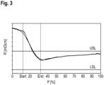
- the method according to the invention was used to show that the specific electrical resistance of the single crystal can be further reduced and kept almost constant between a lower limit LSL and an upper limit USL until the completion of the pulling process.
- Fig.3 The result is shown in the form of a resistance measurement.
- the supply of gaseous dopant in the form of a volume flow of dopant gas according to the invention took place during the pulling of the cylindrical section of the single crystal between the positions marked Start and End.
- the specific resistance in the single crystal could be reduced to less than 1 m ⁇ cm.
Landscapes
- Chemical & Material Sciences (AREA)
- Engineering & Computer Science (AREA)
- Crystallography & Structural Chemistry (AREA)
- Materials Engineering (AREA)
- Metallurgy (AREA)
- Organic Chemistry (AREA)
- Crystals, And After-Treatments Of Crystals (AREA)
Abstract
Description
- Gegenstand der Erfindung ist ein Verfahren zur Herstellung eines Einkristalls aus Silizium, der mit Dotierstoff vom n-Typ dotiert ist, durch Ziehen des Einkristalls in einer Reaktorkammer gemäß der CZ-Methode aus einer Schmelze, die in einem Tiegel enthalten ist.
- Einkristalle aus Silizium, die vergleichsweise viel Dotierstoff vom n-Typ enthalten, werden hauptsächlich als Rohstoffe zur Herstellung von Halbleiter-Leistungsbauelementen benötigt.
- Sublimierende Dotierstoffelemente wie Phosphor oder Arsen oder Antimon werden üblicherweise in gasförmigem Zustand mit der Schmelze in Kontakt gebracht. Dabei besteht die Herausforderung, ungeachtet eines hohen Dampfdrucks des Dotierstoffs, eine ausreichend hohe Konzentration an Dotierstoff in der Schmelze zu gewährleisten. Darüber hinaus muss der Dotierstoffeintrag möglichst genau kontrolliert werden, um zu vermeiden, dass sich Versetzungen bilden, die das einkristalline Wachstum Kristalls beenden.
-
WO 2021/115 904 A1 beschreibt ein Verfahren, wonach in einer Sublimations-Einrichtung Dotierstoffgas erzeugt wird und zusammen mit einem Trägergas durch eine Rohrleitung in die Reaktorkammer bis zu einem Ringkanal an einem unteren Ende eines Hitzeschilds geleitet wird. - In
US 2010/0 294 999 A1 ist beschrieben, festen Dotierstoff in einer beheizten Einheit innerhalb der Reaktorkammer zu sublimieren und die Sublimations-Geschwindigkeit zu regeln sowie dabei entstehendes Dotierstoffgas zusammen mit einem Trägergas durch eine Rohrleitung zur Schmelze zu leiten. - Die Aufgabe dieser Erfindung ist es, auf einfache Weise zu erreichen, dass die Dotierstoff-Verteilung über die axiale Länge eines zylindrischen Abschnitts des Einkristalls möglichst gleichmäßig ist, unabhängig von der Länge des zylindrischen Abschnitts.
- Gelöst wird die Aufgabe durch ein Verfahren zur Herstellung eines Einkristalls aus Silizium, der mit Dotierstoff vom n-Typ dotiert ist, durch Ziehen des Einkristalls, der von einem Hitzeschild mit einem unteren Ende umgeben ist, in einer Reaktorkammer gemäß der CZ-Methode aus einer Schmelze, die in einem Tiegel enthalten ist, umfassend
- das Erhitzen von festem Dotierstoff in einem Dotierstoff-Tiegel einer Sublimier-Einheit außerhalb der Reaktorkammer mittels einer Tiegel-Heizung bis auf eine Temperatur, bei der gasförmiger Dotierstoff gebildet wird;
- das Zuführen des gasförmigen Dotierstoffs in Form eines Volumenstroms von Dotierstoffgas durch eine Rohrleitung mit einem unteren Ende zu einer Oberfläche der Schmelze, gekennzeichnet durch
- das Bringen eines Regelventils zwischen der Sublimier-Einheit und der Reaktorkammer in einen vorgegebenen Öffnungszustand, sobald eine Druckdifferenz des Drucks in der Sublimier-Einheit und des Drucks in der Reaktorkammer auf einen vorbestimmten Wert angewachsen ist; und
- das Regeln des Öffnungszustands des Regelventils mit einem Soll-Druck in der Sublimier-Einheit als Führungsgröße und der Druckdifferenz als Regelgröße der Regelung.
- Mittels der Erfindung kann während des Ziehens eines Einkristalls ein nahezu gleichbleibender Strom an Dotierstoffgas über einen vergleichsweisen langen Zeitraum zur Schmelze geleitet werden und fester Dotierstoff bei Bedarf nachbeladen werden, um eine weitere Zufuhr von Dotierstoffgas zur Schmelze zu gewährleisten. Die Lösung ist einfach und zuverlässig.
- Der gasförmige Dotierstoff wird ohne oder zusammen mit einem Trägergas wie Argon als Volumenstrom von Dotierstoffgas zur Schmelze geleitet. Das Trägergas wird insbesondere eingesetzt, um den Strom an gasförmigen Dotierstoff zu stabilisieren, wenn die Konzentration an gasförmigem Dotierstoff vergleichsweise gering ist. Die Zufuhr von Trägergas wird vorzugsweise mittels eines Massendurchfluss-Reglers (MFC) geregelt.
- Fester Dotierstoff kann vor und/oder während des Ziehens eines Einkristalls in den Dotierstoff-Tiegel gefüllt werden. Zum Nachbeladen des Dotierstoff-Tiegels mit festem Dotierstoff wird die Rohrleitung außerhalb der Reaktorkammer unterbrochen, indem das Regelventil (control valve) vollständig geschlossen wird. Vorzugsweise wird sicherheitshalber zusätzlich ein Trennventil aktiviert, das zwischen der Reaktorkammer und dem Regelventil angeordnet sein kann. Das Trennventil stellt sicher, dass unabhängig von der Dichtigkeit des Regelventils ein sicherer Zugang zur Sublimier-Einheit gewährleistet ist. Vorzugsweise wird die Temperatur des Dotierstoff-Tiegels und damit die Temperatur in der Sublimier-Einheit, kurz bevor der darin enthaltene feste Dotierstoff aufgebraucht ist, angehoben. Dadurch wird gewährleistet, dass der Dotierstoff vollständig entwichen ist, bevor die Sublimier-Einheit geöffnet wird. Das Entweichen des Dotierstoffs kann durch den damit verbundenen Druckabfall in der Sublimier-Einheit verfolgt werden.
- Die Sublimier-Einheit umfasst ein Gehäuse, in dem der Dotierstoff-Tiegel untergebracht ist und das einen Zugang zum Dotierstoff-Tiegel gewährt. Das Gehäuse ist vorzugsweise doppelwandig ausgeführt und kann mittels eines Kühlkreislaufs aktiv gekühlt werden.
- Neben der Tiegel-Heizung sind vorzugsweise weitere Heizungen vorhanden, insbesondere um einer Resublimation des Dotierstoffs entgegenzuwirken, beispielsweise eine Innenraum-Heizung für das Gehäuse, eine Außenheizung für das Regelventil und das gegebenenfalls vorhandene Trennventil und die außerhalb der Reaktorkammer befindlichen Bereiche der Rohrleitung. Eine weitere Heizung kann zum Beheizen von Ventilen zum Einleiten des Trägergases und von Umgebungsluft in die Sublimier-Einheit vorgesehen sein. Für roten Phosphor als Dotierstoff beträgt die Sublimationstemperatur 362 °C bei einem Druck von 10000 Pa, für Arsen ist die Sublimationstemperatur bei diesem Druck 508 °C. Insbesondere die Temperatur der Dotierstoff führenden Rohrleitung sollte über der entsprechenden Sublimationstemperatur liegen.
- Der Druck wird in der Reaktorkammer und in der Sublimier-Einheit gemessen. Der Öffnungszustand des Regelventils wird von der Differenz der Drücke in der Sublimier-Einheit und der Reaktorkammer abhängig gemacht und mittels eines Aktuators des Regelventils eingestellt. Der Aktuator stellt den Hub (stroke) eines Elements ein, das den Durchfluss durch das Ventil bestimmt, beispielsweise die Position eines Stopfens, der den Durchfluss durch das Ventil unterbrechen kann. Der Aktuator arbeitet vorzugsweise elektrisch und bildet das Stellglied einer Regelung. Während des Zuführens des gasförmigen Dotierstoffs zur Oberfläche der Schmelze ist der Druck in der Sublimier-Einheit größer als der Druck in der Reaktorkammer.
- Um zu erreichen, dass der Volumenstrom von Dotierstoffgas während eines Vorgangs des Ziehens eines Einkristalls aus Silizium in reproduzierbarer und kontrollierter Weise zur Schmelze gelangt, wird der Volumenstrom vorzugsweise erst nach einer Stabilisierungsphase durch das Regelventil geleitet. Die Stabilisierungsphase umfasst das Erhitzen des Dotierstoff-Tiegels bei geschlossenem Regelventil auf eine Temperatur, die unter der Temperatur liegt, bei der der feste Dotierstoff zu sublimieren beginnt, bis der Druck in der Sublimier-Einheit auf einen vorbestimmten Wert angestiegen ist. Nach der Stabilisierungsphase wird der Dotierstoff-Tiegel auf eine Temperatur erhitzt, die über der Temperatur liegt, bei der der feste Dotierstoff zu sublimieren beginnt. Die Geschwindigkeit (evaporation rate), mit der der feste Dotierstoff sublimiert, wird insbesondere durch die Temperatur bestimmt, auf die der Dotierstoff-Tiegel erhitzt wird. Ein einsetzender weiterer Druckanstieg in der Sublimier-Einheit bei gleichbleibender oder leicht steigender Temperatur der Heizung des Dotierstoff-Tiegels zeigt den Beginn der Sublimation an. Das Regelventil wird geöffnet, sobald die Differenz des Drucks in der Sublimier-Einheit und des Drucks in der Reaktorkammer auf einen vorbestimmten Wert angewachsen ist. Die Druckdifferenz beträgt vorzugsweise mindestens 1000 Pa, besonders bevorzugt 5000 bis 10000 Pa. Anschließend wird der Öffnungszustands des Regelventils mittels eines Aktuators des Regelventils im Rahmen einer Regelung geregelt, mit einem Soll-Druck in der Sublimier-Einheit als Führungsgröße und der Druckdifferenz als Regelgröße der Regelung. Die Regelung ist vorzugsweise als PID-Regelung ausgestaltet. Der Druck bleibt in der Sublimier-Einheit mit Ausnahme von periodischen, der Regelung geschuldeten Druckschwankungen nahezu konstant, bis es zu einem Druckabfall kommt, der wegen des zur Neige gehenden Vorrats an festem Dotierstoff im Dotierstoff-Tiegel eintritt. Fällt der Druck auf einen vorgesehenen Wert, wird auch das Regelventil geschlossen.
- Der Dotierstoff-Tiegel kann mit festem Dotierstoff nachbeladen werden, sollte es notwendig sein, aus der Schmelze entwichenen Dotierstoff zu ersetzen. Das kann der Fall sein, wenn nach einer Versetzungsbildung der Kristall zurückgeschmolzen und ein neuer Anlauf zum Ziehen eines Einkristalls begonnen wird oder wenn wegen der Länge des zylindrischen Abschnitts des wachsenden Einkristalls der Vorrat an Dotierstoff in der Sublimier-Einheit erschöpft ist. Dann wird die Sublimier-Einheit bei geschlossenem Regelventil und gegebenenfalls geschlossenem Trennventil gespült und abgekühlt und die erforderliche Menge an zusätzlichem festen Dotierstoff im Dotierstoff-Tiegel abgelegt.
- Das Zuführen des Volumenstroms von Dotierstoffgas durch die Rohrleitung zur Oberflache der Schmelze beginnt vorzugsweise vor dem Ziehen eines zylindrischen Abschnitts des Einkristalls, beispielsweise gleich nach dem In-Kontakt-Bringen eines Impflings-Kristalls mit der Schmelze oder vor oder während des Ziehens eines konusförmigen Abschnitts des Einkristalls. Es ist aber auch möglich, erst am Anfang oder während des Ziehens des zylindrischen Abschnitts damit zu beginnen. Unabhängig davon kann die Schmelze bereits vor dem Zuführen des Volumenstroms von Dotierstoffgas mit Dotierstoff angereichert sein, beispielsweise indem eine Dotierglocke mit festem Dotierstoff in die Schmelze aus Silizium getaucht wird.
- Das untere Ende der Rohrleitung, an dem der Volumenstrom von Dotierstoffgas austritt, ist vorzugsweise auf derselben Höhe über der Schmelze angeordnet, wie das untere Ende eines Hitzeschilds, der den wachsenden Einkristall umgibt. Des Weiteren befindet sich das untere Ende der Rohrleitung vorzugsweise zwischen dem unteren Ende des Hitzeschilds und der Wand des Tiegels mit der Schmelze. Es ist auch bevorzugt, die Rohrleitung in der Reaktorkammer so anzuordnen, dass sie durch die Wand des Hitzeschilds hindurchführt. Die Rohrleitung besteht im Bereich der Wand der Reaktorkammer, wo sie mit Wasser gekühlt werden kann, vorzugsweise aus Metall, beispielsweise aus Edelstahl, und ist dort einer Temperatur von nicht mehr als 600 °C ausgesetzt. In der Umgebung des wachsenden Einkristalls und wärmerer Grafit-Teile, der hot zone, muss temperaturfestes Material verwendet werden, beispielsweise Grafit, ein carbon fibre reinforced composit-Werkstoff (CFC) und oder Quarz. Es ist besonders bevorzugt, die Rohrleitung in der Reaktorkammer in einen oberen Abschnitt aus Edelstahl, einen mittleren Abschnitt aus CFC und einen unteren Abschnitt aus Quarz, der an seinem unteren Ende mit CFC ummantelt ist, zu untergliedern. Die Ummantelung schützt das Quarzrohr vor Überhitzung.
- Die Erfindung wird nachfolgend unter Bezugnahme auf Zeichnungen weiter beschrieben.
-
-
Fig. 1 zeigt einen Vertikalschnitt durch eine Reaktorkammer und eine Sublimier-Einheit, die zur Umsetzung der Erfindung geeignet sind. -
Fig. 2 zeigt einen vergrößerten Ausschnitt vonFig. 1 -
Fig. 3 zeigt den Verlauf des spezifischen elektrischen Widerstands R eines Einkristalls aus Silizium in Abhängigkeit der axialen Position P des zylindrischen Abschnitts des Einkristalls. -
- 1
- Reaktorkammer
- 2
- Sublimier-Einheit
- 3
- Tiegel
- 4
- Schmelze
- 5
- Einkristall
- 6
- Rohrleitung
- 7
- Heizvorrichtung
- 8
- Ziehvorrichtung
- 9
- Magnetfeld-Spule
- 10
- Hitzeschild
- 11
- Dotierstoff-Tiegel
- 12
- Tiegel-Heizung
- 13
- Wägezelle
- 14
- Massendurchfluss-Regler
- 15
- Controller
- 16
- Regelventil
- 17
- Trennventil
- 18
- oberer Abschnitt
- 19
- mittlerer Abschnitt
- 20
- unterer Abschnitt
- 21
- CFC-Mantel
-
Fig. 1 zeigt einen Vertikalschnitt durch eine Reaktorkammer 1 und eine Sublimier-Einheit 2, die zur Umsetzung der Erfindung geeignet sind. Die nachfolgende Beschreibung lässt einige gezeigte Merkmale unerwähnt, die zur Erklärung der Erfindung nichts beitragen. In der Reaktorkammer 1 ist ein Tiegel 3 mit einer Schmelze 4 aus Silizium angeordnet, die im Verlauf des Ziehens eines Einkristalls 5 aus der Schmelze mit gasförmigem Dotierstoff vom n-Typ, der durch eine Rohrleitung 6 zur Oberfläche der Schmelze 4 geführt wird, dotiert wird. Die Schmelze 4 wird mittels einer Heizvorrichtung 7, die den Tiegel 3 umgibt, flüssig gehalten. Der Einkristall 5 ist von einem Hitzeschild 10 umgeben, der Wärmestrahlung der Heizvorrichtung 7 abschirmt. Während der Einkristall 5 mittels einer Ziehvorrichtung 8 gedreht und aus der Schmelze gezogen wird, wird der Tiegel 3 angehoben und gedreht. Das Beaufschlagen der Schmelze 4 mit einem Magnetfeld, beispielsweise einem horizontalen Magnetfeld, mittels einer oder mehrerer Magnetfeld-Spulen 9, die um die Reaktorkammer 1 herum angeordnet sind, ist möglich, aber nicht zwingend notwendig. Während des Ziehens des Einkristalls 5 wir die Reaktorkammer 1 gespült, beispielsweise mittels eines Stroms von Argon, der durchgeleitet wird. - Der gasförmige Dotierstoff wird in der Sublimier-Einheit 2 erzeugt, die sich außerhalb der Reaktorkammer befindet, und von dort in Form eines Volumenstroms von Dotierstoffgas durch die Rohrleitung 6 zur Oberfläche der Schmelze 4 geführt. Der Volumenstrom kann anteilig Trägergas, beispielsweise Argon enthalten, das über einen Massendurchfluss-Regler 14 in die Sublimier-Einheit geleitet wird. Zum Erzeugen des gasförmigen Dotierstoffs wird fester Dotierstoff, beispielsweise roter Phosphor, in einen Dotierstoff-Tiegel 11 gefüllt und der Dotierstoff-Tiegel 11 mittels einer Tiegel-Heizung 12 in der Sublimier-Einheit 2 erhitzt. Die Sublimier-Einheit 2 kann über eine Wägezelle 13 verfügen, die über das aktuelle Gewicht an festem Dotierstoff im Dotierstoff-Tiegel 11 informiert. Auf dem Weg durch die Rohrleitung 6 passiert der Volumenstrom von Dotiergas nach dem Verlassen der Sublimier-Einheit 2 und vor dem Eintritt in die Reaktorkammer 1 ein Regelventil 16 und gegebenenfalls ein Trennventil 17.
- Der Druck und die Temperatur in der Reaktorkammer 1 und in der Sublimier-Einheit 2 werden von Sensoren an einen Controller 15 übermittelt, der zur Regelung der Zufuhr von Dotierstoffgas zur Oberfläche der Schmelze 4 eingesetzt wird. In der dargestellten Ausführungsform wird der Controller 15 auch verwendet, um den Ziehprozess zu steuern, beispielsweise das Drehen und Herausziehen des Einkristalls 5 und das Drehen und Anheben des Tiegels 3. Zum Initiieren der Zufuhr von gasförmigen Dotierstoff zur Oberfläche der Schmelze 4 wird der Dotierstoff-Tiegel 11 mittels der Tiegel-Heizung 12 erhitzt. Währenddessen hält der Controller 15 das Regelventil 16 und das Trennventil 17 (sofern vorhanden) geschlossen. Zunächst wird der feste Dotierstoff im Dotierstoff-Tiegel 11 auf eine Temperatur unterhalb der Sublimationstemperatur vorerhitzt, bis der Druck in der Sublimier-Einheit 2 eine vorgegebene Schwelle erreicht hat. Anschließend wird die Temperatur der Tiegel-Heizung 12 auf eine Zieltemperatur über der Sublimationstemperatur erhöht, was einen weiteren Druckanstieg in der Sublimier-Einheit 2 zur Folge hat. Der Controller 15 bringt das Regelventil 16 in einen vorgegebenen Öffnungszustand und öffnet gegebenenfalls das Trennventil 17, sobald die Differenz des Drucks in der Sublimier-Einheit 2 und des Drucks in der Reaktorkammer 1 auf einen vorbestimmten Wert angewachsen ist. Im weiteren Verlauf wird der Öffnungszustand des Regelventils 16 geregelt, wobei ein Soll-Druck in der Sublimier-Einheit 2 die Führungsgröße der Regelung ist. Wenn der Vorrat an festem Dotierstoff im Dotierstoff-Tiegel zur Neige geht, fällt der Druck in der Sublimier-Einheit 2. Ist der Druck auf einen vorgegebenen Wert gefallen, werden das Regelventil 16 und gegebenenfalls das Trennventil 17 geschlossen. Danach kann im Bedarfsfall noch während des Ziehens des Einkristalls 5 der Dotierstoff-Tiegel 11 mit weiterem festen Dotierstoff beladen und ein neuer Zyklus des Zuführens des gasförmigen Dotierstoffs zur Oberfläche der Schmelze 4 begonnen werden.
- Gemäß der in
Fig. 1 gezeigten bevorzugten Ausführungsform hat das untere Ende der Rohrleitung 6 denselben Abstand zur Oberfläche der Schmelze 4 wie das untere Ende des Hitzeschilds 10. Des Weiteren ist bei dieser Ausführungsform der Verlauf der Rohrleitung 6 in der Reaktorkammer 1 so gestaltet, dass die Rohrleitung 6 durch den Hitzeschild 10 hindurchführt, und das untere Ende der Rohrleitung 6 zwischen einer Wand des Tiegels 3 und dem unteren Ende des Hitzeschilds 10 angeordnet ist. - Gemäß dieser bevorzugten Ausgestaltung und der Darstellung in
Fig. 2 ist die Rohrleitung 6 in der Reaktorkammer 1 in drei Abschnitte untergliedert und zwar in einen oberen Abschnitt 18 aus Edelstahl, einen mittleren Abschnitt 19 aus CFC (carbon fiber carbon composite) und einen unteren Abschnitt 20 aus Quarz, der an seinem unteren Ende von einem CFC-Mantel umgeben ist. - Die Wirksamkeit der Erfindung wurde am Beispiel der Herstellung eines Einkristalls aus Silizium mit einem Durchmesser von 200 mm in einer Anlage getestet, die im Wesentlichen die in
Fig.1 dargestellten Merkmale umfasste. Die Sublimier-Einheit stammte vom Hersteller Riber aus Frankreich. - Zunächst wurde der Einkristall bis zu einem oberen, zylindrischen Abschnitt mit einer Grunddotierung durch Phosphor gezogen, der der Schmelze vor dem Ziehen mittels einer Dotierglocke hinzugefügt worden war. Das erfindungsgemäße Verfahren wurde verwendet, um zu zeigen, dass der spezifische elektrische Widerstand des Einkristalls weiter abgesenkt und bis zum Abschluss des Ziehvorgangs nahezu konstant zwischen einer unteren Grenze LSL und einer oberen Grenze USL gehalten werden kann. In
Fig. 3 ist das Ergebnis in Form einer Widerstandsmessung dargestellt. Der Verlauf des Widerstands ist vom Anfang des zylindrischen Abschnitts mit Position P = 0 bis zum Ende des zylindrischen Abschnitts mit Position P = 100 gezeigt. Das erfindungsgemäße Zuführen von gasförmigem Dotierstoff in Form eines Volumenstroms von Dotierstoffgas erfolgte während des Ziehens des zylindrischen Abschnitts des Einkristalls zwischen den mit Start und End bezeichneten Positionen. Durch Anwenden des erfindungsgemäßen Verfahrens konnte der spezifische Widerstand im Einkristall auf weniger als 1 mΩcm herabgesetzt werden.
Claims (7)
- Verfahren zur Herstellung eines Einkristalls aus Silizium, der mit Dotierstoff vom n-Typ dotiert ist, durch Ziehen des Einkristalls, der von einem Hitzeschild mit einem unteren Ende umgeben ist, in einer Reaktorkammer gemäß der CZ-Methode aus einer Schmelze, die in einem Tiegel enthalten ist, umfassenddas Erhitzen von festem Dotierstoff in einem Dotierstoff-Tiegel einer Sublimier-Einheit außerhalb der Reaktorkammer mittels einer Tiegel-Heizung bis auf eine Temperatur, bei der gasförmiger Dotierstoff gebildet wird;das Zuführen des gasförmigen Dotierstoffs in Form eines Volumenstroms von Dotierstoffgas durch eine Rohrleitung mit einem unteren Ende zu einer Oberfläche der Schmelze, gekennzeichnet durchdas Bringen eines Regelventils zwischen der Sublimier-Einheit und der Reaktorkammer in einen vorgegebenen Öffnungszustand, sobald eine Druckdifferenz des Drucks in der Sublimier-Einheit und des Drucks in der Reaktorkammer auf einen vorbestimmten Wert angewachsen ist; unddas Regeln des Öffnungszustands des Regelventils mit einem Soll-Druck in der Sublimier-Einheit als Führungsgröße und der Druckdifferenz als Regelgröße der Regelung.
- Verfahren nach Anspruch 1, dadurch gekennzeichnet, dass die Regelung als PID-Regelung ausgestaltet ist.
- Verfahren nach Anspruch 1 oder Anspruch 2, dadurch gekennzeichnet, dass das untere Ende der Rohrleitung denselben Abstand zur Oberfläche der Schmelze hat wie das untere Ende des Hitzeschilds.
- Verfahren nach einem der Ansprüche 1 bis 3, dadurch gekennzeichnet, dass die Rohrleitung durch den Hitzeschild hindurchführt und das untere Ende der Rohrleitung zwischen einer Wand des Tiegels und dem unteren Ende des Hitzeschilds angeordnet ist.
- Verfahren nach einem der Ansprüche 1 bis 4, dadurch gekennzeichnet, dass die Rohrleitung in einen oberen Abschnitt aus Edelstahl, einen mittleren Abschnitt aus CFC und einen unteren Abschnitt aus Quarz, der mit CFC ummantelt ist, gegliedert ist.
- Verfahren nach einem der Ansprüche 1 bis 5, dadurch gekennzeichnet, dass die Rohrleitung zwischen der Sublimier-Einheit und der Reaktorkammer durch ein Trennventil geschlossen wird, bevor der Dotierstoff-Tiegel mit weiterem festem Dotierstoff nachbeladen wird.
- Verfahren nach einem der Ansprüche 1 bis 6, dadurch gekennzeichnet, dass die Temperatur des Dotierstoff-Tiegels, kurz bevor der darin enthaltene feste Dotierstoff aufgebraucht ist, angehoben wird.
Priority Applications (8)
| Application Number | Priority Date | Filing Date | Title |
|---|---|---|---|
| FIEP22201615.6T FI4353878T3 (fi) | 2022-10-14 | 2022-10-14 | Menetelmä piistä valmistetun monokiteen, joka on seostettu epäpuhtausaineella, valmistukseen cz-menetelmän mukaisesti |
| EP22201615.6A EP4353878B1 (de) | 2022-10-14 | 2022-10-14 | Verfahren zur herstellung eines einkristalls aus silizium, der mit dotierstoff vom n-typ dotiert ist, gemäss der cz-methode |
| KR1020257015690A KR20250085829A (ko) | 2022-10-14 | 2023-09-28 | CZ 방법에 의해 n-타입 도펀트로 도핑된 실리콘 단결정 제조 프로세스 |
| PCT/EP2023/076932 WO2024078888A1 (de) | 2022-10-14 | 2023-09-28 | VERFAHREN ZUR HERSTELLUNG EINES EINKRISTALLS AUS SILIZIUM, DER MIT DOTIERSTOFF VOM N-TYP DOTIERT IST, GEMÄß DER CZ-METHODE |
| US19/113,458 US20260092392A1 (en) | 2022-10-14 | 2023-09-28 | Method for producing a single crystal of silicon which is doped with n-type dopant according to the cz method |
| CN202380070389.4A CN120019177A (zh) | 2022-10-14 | 2023-09-28 | 通过CZ法生产掺杂有n型掺杂剂的单晶硅的工艺 |
| JP2025521162A JP2025534170A (ja) | 2022-10-14 | 2023-09-28 | CZ法によるn型ドーパントがドープされた単結晶シリコンを製造するための方法 |
| TW112138584A TWI898279B (zh) | 2022-10-14 | 2023-10-06 | 藉由CZ法生產摻雜n型摻雜劑的單矽晶體的方法 |
Applications Claiming Priority (1)
| Application Number | Priority Date | Filing Date | Title |
|---|---|---|---|
| EP22201615.6A EP4353878B1 (de) | 2022-10-14 | 2022-10-14 | Verfahren zur herstellung eines einkristalls aus silizium, der mit dotierstoff vom n-typ dotiert ist, gemäss der cz-methode |
Publications (2)
| Publication Number | Publication Date |
|---|---|
| EP4353878A1 true EP4353878A1 (de) | 2024-04-17 |
| EP4353878B1 EP4353878B1 (de) | 2025-04-23 |
Family
ID=83692923
Family Applications (1)
| Application Number | Title | Priority Date | Filing Date |
|---|---|---|---|
| EP22201615.6A Active EP4353878B1 (de) | 2022-10-14 | 2022-10-14 | Verfahren zur herstellung eines einkristalls aus silizium, der mit dotierstoff vom n-typ dotiert ist, gemäss der cz-methode |
Country Status (8)
| Country | Link |
|---|---|
| US (1) | US20260092392A1 (de) |
| EP (1) | EP4353878B1 (de) |
| JP (1) | JP2025534170A (de) |
| KR (1) | KR20250085829A (de) |
| CN (1) | CN120019177A (de) |
| FI (1) | FI4353878T3 (de) |
| TW (1) | TWI898279B (de) |
| WO (1) | WO2024078888A1 (de) |
Citations (2)
| Publication number | Priority date | Publication date | Assignee | Title |
|---|---|---|---|---|
| US20100294999A1 (en) | 2007-04-24 | 2010-11-25 | Sumco Techxiv Corporation | Producing method and apparatus of silicon single crystal, and silicon single crystal ingot |
| WO2021115904A1 (de) | 2019-12-13 | 2021-06-17 | Siltronic Ag | Verfahren und vorrichtung zur herstellung eines einkristalls aus silizium, der mit dotierstoff vom n-typ dotiert ist |
Family Cites Families (2)
| Publication number | Priority date | Publication date | Assignee | Title |
|---|---|---|---|---|
| JP3709307B2 (ja) * | 1999-07-21 | 2005-10-26 | シルトロニック・ジャパン株式会社 | シリコン単結晶製造方法および製造装置 |
| US6312517B1 (en) * | 2000-05-11 | 2001-11-06 | Memc Electronic Materials, Inc. | Multi-stage arsenic doping process to achieve low resistivity in silicon crystal grown by czochralski method |
-
2022
- 2022-10-14 FI FIEP22201615.6T patent/FI4353878T3/fi active
- 2022-10-14 EP EP22201615.6A patent/EP4353878B1/de active Active
-
2023
- 2023-09-28 CN CN202380070389.4A patent/CN120019177A/zh active Pending
- 2023-09-28 KR KR1020257015690A patent/KR20250085829A/ko active Pending
- 2023-09-28 JP JP2025521162A patent/JP2025534170A/ja active Pending
- 2023-09-28 US US19/113,458 patent/US20260092392A1/en active Pending
- 2023-09-28 WO PCT/EP2023/076932 patent/WO2024078888A1/de not_active Ceased
- 2023-10-06 TW TW112138584A patent/TWI898279B/zh active
Patent Citations (2)
| Publication number | Priority date | Publication date | Assignee | Title |
|---|---|---|---|---|
| US20100294999A1 (en) | 2007-04-24 | 2010-11-25 | Sumco Techxiv Corporation | Producing method and apparatus of silicon single crystal, and silicon single crystal ingot |
| WO2021115904A1 (de) | 2019-12-13 | 2021-06-17 | Siltronic Ag | Verfahren und vorrichtung zur herstellung eines einkristalls aus silizium, der mit dotierstoff vom n-typ dotiert ist |
Also Published As
| Publication number | Publication date |
|---|---|
| KR20250085829A (ko) | 2025-06-12 |
| JP2025534170A (ja) | 2025-10-14 |
| US20260092392A1 (en) | 2026-04-02 |
| WO2024078888A1 (de) | 2024-04-18 |
| TW202415816A (zh) | 2024-04-16 |
| EP4353878B1 (de) | 2025-04-23 |
| TWI898279B (zh) | 2025-09-21 |
| CN120019177A (zh) | 2025-05-16 |
| FI4353878T3 (fi) | 2025-07-23 |
Similar Documents
| Publication | Publication Date | Title |
|---|---|---|
| EP2804964B1 (de) | Verfahren und vorrichtung zur vakuumdestillation von hochreinem magnesium | |
| DE19622659C2 (de) | Vertikalofen zur Züchtung von Einkristallen | |
| DE69902911T2 (de) | Widerstandsheizung fur eine kristallzüchtungsvorrichtung und verfahren zu ihrer verwendung | |
| DE69713529T2 (de) | Schnelle Kühlung einer CZ-Silizium-Einkristallzüchtungsvorrichtung | |
| DE112018002156B4 (de) | Verfahren zur Herstellung eines Silicium-Einkristalls vom n-Typ, Silicium-Einkristall-Ingot vom n-Typ, Siliciumwafer und epitaktischer Siliciumwafer | |
| DE102021123991B4 (de) | PVT-Verfahren und Apparatur zum prozesssicheren Herstellen von Einkristallen | |
| DE112009003601B4 (de) | Einkristall-Herstellungsanlage und Verfahren zur Herstellung elnes Einkristalls | |
| DE102017217540A1 (de) | Herstellungsverfahren für einkristallines Silicium und einkristallines Silicium | |
| DE112009001431B4 (de) | Einkristall-Herstellungsvorrichtung und Einkristall-Herstellungsverfahren | |
| DE60221908T2 (de) | Verfahren und vorrichtung zum verdampfen eines flüssigen vorlaüfers beim herstellen einer glasvorform | |
| DE112017007122T5 (de) | Verfahren zur Herstellung von Silizium-Monokristall, Strömungsausrichtungselement und Monokristall-Ziehvorrichtung | |
| DE112017003016B4 (de) | Verfahren zur Herstellung von Silicium-Einkristall | |
| EP4353878B1 (de) | Verfahren zur herstellung eines einkristalls aus silizium, der mit dotierstoff vom n-typ dotiert ist, gemäss der cz-methode | |
| DE2219687A1 (de) | Vorrichtung zum Herstellen und Wachstum eines kristallinen Stoffes | |
| DE1769860A1 (de) | Vorrichtung zum Ziehen von versetzungsfreien Halbleitereinkristallstaeben | |
| DE112006002595T5 (de) | Herstellungsvorrichtung und Herstellungsverfahren für ein Einkristall-Halbleiter | |
| DE102007046409B4 (de) | Vorrichtung zur Herstellung von Kristallen aus elektrisch leitenden Schmelzen | |
| DE102012005069A1 (de) | "Verfahren und Vorrichtung zum Herstellen von solartauglichen Siliziumblöcken" | |
| DE112017003224B4 (de) | Verfahren zur Herstellung von Silicium-Einkristall | |
| DE112005000300B4 (de) | Verfahren zum Herstellen eines Einkristall-Halbleiters | |
| DE19704075A1 (de) | Verfahren und Vorrichtung zur Herstellung von Einkristallen in Ampullen unter Magnetfeldeinfluß | |
| EP2880205B1 (de) | Vorrichtung zur herstellung eines einkristalls durch kristallisieren des einkristalls an einer schmelzenzone | |
| DE10207284A1 (de) | Verfahren zur Herstellung eines hochdotierten Einkristalls aus Silicium | |
| DE19842109A1 (de) | Züchtungsapparatur zum Züchten von SiC-Einkristallen | |
| DE102007006731B4 (de) | Verfahren und Vorrichtung zur Herstellung von Zinkoxid-Einkristallen aus einer Schmelze |
Legal Events
| Date | Code | Title | Description |
|---|---|---|---|
| PUAI | Public reference made under article 153(3) epc to a published international application that has entered the european phase |
Free format text: ORIGINAL CODE: 0009012 |
|
| STAA | Information on the status of an ep patent application or granted ep patent |
Free format text: STATUS: THE APPLICATION HAS BEEN PUBLISHED |
|
| AK | Designated contracting states |
Kind code of ref document: A1 Designated state(s): AL AT BE BG CH CY CZ DE DK EE ES FI FR GB GR HR HU IE IS IT LI LT LU LV MC ME MK MT NL NO PL PT RO RS SE SI SK SM TR |
|
| STAA | Information on the status of an ep patent application or granted ep patent |
Free format text: STATUS: REQUEST FOR EXAMINATION WAS MADE |
|
| 17P | Request for examination filed |
Effective date: 20240813 |
|
| RBV | Designated contracting states (corrected) |
Designated state(s): AL AT BE BG CH CY CZ DE DK EE ES FI FR GB GR HR HU IE IS IT LI LT LU LV MC ME MK MT NL NO PL PT RO RS SE SI SK SM TR |
|
| GRAP | Despatch of communication of intention to grant a patent |
Free format text: ORIGINAL CODE: EPIDOSNIGR1 |
|
| STAA | Information on the status of an ep patent application or granted ep patent |
Free format text: STATUS: GRANT OF PATENT IS INTENDED |
|
| RIC1 | Information provided on ipc code assigned before grant |
Ipc: C30B 29/06 20060101ALI20241024BHEP Ipc: C30B 15/04 20060101AFI20241024BHEP |
|
| INTG | Intention to grant announced |
Effective date: 20241105 |
|
| GRAS | Grant fee paid |
Free format text: ORIGINAL CODE: EPIDOSNIGR3 |
|
| GRAA | (expected) grant |
Free format text: ORIGINAL CODE: 0009210 |
|
| STAA | Information on the status of an ep patent application or granted ep patent |
Free format text: STATUS: THE PATENT HAS BEEN GRANTED |
|
| AK | Designated contracting states |
Kind code of ref document: B1 Designated state(s): AL AT BE BG CH CY CZ DE DK EE ES FI FR GB GR HR HU IE IS IT LI LT LU LV MC ME MK MT NL NO PL PT RO RS SE SI SK SM TR |
|
| REG | Reference to a national code |
Ref country code: GB Ref legal event code: FG4D Free format text: NOT ENGLISH |
|
| REG | Reference to a national code |
Ref country code: CH Ref legal event code: EP |
|
| REG | Reference to a national code |
Ref country code: DE Ref legal event code: R096 Ref document number: 502022003659 Country of ref document: DE |
|
| REG | Reference to a national code |
Ref country code: IE Ref legal event code: FG4D Free format text: LANGUAGE OF EP DOCUMENT: GERMAN |
|
| REG | Reference to a national code |
Ref country code: FI Ref legal event code: FGE |
|
| REG | Reference to a national code |
Ref country code: NL Ref legal event code: MP Effective date: 20250423 |
|
| PG25 | Lapsed in a contracting state [announced via postgrant information from national office to epo] |
Ref country code: NL Free format text: LAPSE BECAUSE OF FAILURE TO SUBMIT A TRANSLATION OF THE DESCRIPTION OR TO PAY THE FEE WITHIN THE PRESCRIBED TIME-LIMIT Effective date: 20250423 |
|
| PG25 | Lapsed in a contracting state [announced via postgrant information from national office to epo] |
Ref country code: PT Free format text: LAPSE BECAUSE OF FAILURE TO SUBMIT A TRANSLATION OF THE DESCRIPTION OR TO PAY THE FEE WITHIN THE PRESCRIBED TIME-LIMIT Effective date: 20250825 Ref country code: ES Free format text: LAPSE BECAUSE OF FAILURE TO SUBMIT A TRANSLATION OF THE DESCRIPTION OR TO PAY THE FEE WITHIN THE PRESCRIBED TIME-LIMIT Effective date: 20250423 |
|
| REG | Reference to a national code |
Ref country code: LT Ref legal event code: MG9D |
|
| PG25 | Lapsed in a contracting state [announced via postgrant information from national office to epo] |
Ref country code: NO Free format text: LAPSE BECAUSE OF FAILURE TO SUBMIT A TRANSLATION OF THE DESCRIPTION OR TO PAY THE FEE WITHIN THE PRESCRIBED TIME-LIMIT Effective date: 20250723 Ref country code: GR Free format text: LAPSE BECAUSE OF FAILURE TO SUBMIT A TRANSLATION OF THE DESCRIPTION OR TO PAY THE FEE WITHIN THE PRESCRIBED TIME-LIMIT Effective date: 20250724 |
|
| PG25 | Lapsed in a contracting state [announced via postgrant information from national office to epo] |
Ref country code: PL Free format text: LAPSE BECAUSE OF FAILURE TO SUBMIT A TRANSLATION OF THE DESCRIPTION OR TO PAY THE FEE WITHIN THE PRESCRIBED TIME-LIMIT Effective date: 20250423 |
|
| PG25 | Lapsed in a contracting state [announced via postgrant information from national office to epo] |
Ref country code: BG Free format text: LAPSE BECAUSE OF FAILURE TO SUBMIT A TRANSLATION OF THE DESCRIPTION OR TO PAY THE FEE WITHIN THE PRESCRIBED TIME-LIMIT Effective date: 20250423 |
|
| PG25 | Lapsed in a contracting state [announced via postgrant information from national office to epo] |
Ref country code: HR Free format text: LAPSE BECAUSE OF FAILURE TO SUBMIT A TRANSLATION OF THE DESCRIPTION OR TO PAY THE FEE WITHIN THE PRESCRIBED TIME-LIMIT Effective date: 20250423 |
|
| PG25 | Lapsed in a contracting state [announced via postgrant information from national office to epo] |
Ref country code: RS Free format text: LAPSE BECAUSE OF FAILURE TO SUBMIT A TRANSLATION OF THE DESCRIPTION OR TO PAY THE FEE WITHIN THE PRESCRIBED TIME-LIMIT Effective date: 20250723 |
|
| PG25 | Lapsed in a contracting state [announced via postgrant information from national office to epo] |
Ref country code: IS Free format text: LAPSE BECAUSE OF FAILURE TO SUBMIT A TRANSLATION OF THE DESCRIPTION OR TO PAY THE FEE WITHIN THE PRESCRIBED TIME-LIMIT Effective date: 20250823 |
|
| PG25 | Lapsed in a contracting state [announced via postgrant information from national office to epo] |
Ref country code: LV Free format text: LAPSE BECAUSE OF FAILURE TO SUBMIT A TRANSLATION OF THE DESCRIPTION OR TO PAY THE FEE WITHIN THE PRESCRIBED TIME-LIMIT Effective date: 20250423 |
|
| PGFP | Annual fee paid to national office [announced via postgrant information from national office to epo] |
Ref country code: DE Payment date: 20251021 Year of fee payment: 4 |
|
| PG25 | Lapsed in a contracting state [announced via postgrant information from national office to epo] |
Ref country code: SM Free format text: LAPSE BECAUSE OF FAILURE TO SUBMIT A TRANSLATION OF THE DESCRIPTION OR TO PAY THE FEE WITHIN THE PRESCRIBED TIME-LIMIT Effective date: 20250423 Ref country code: DK Free format text: LAPSE BECAUSE OF FAILURE TO SUBMIT A TRANSLATION OF THE DESCRIPTION OR TO PAY THE FEE WITHIN THE PRESCRIBED TIME-LIMIT Effective date: 20250423 |
|
| PGFP | Annual fee paid to national office [announced via postgrant information from national office to epo] |
Ref country code: AT Payment date: 20260113 Year of fee payment: 4 |
|
| PGFP | Annual fee paid to national office [announced via postgrant information from national office to epo] |
Ref country code: FI Payment date: 20251028 Year of fee payment: 4 Ref country code: IT Payment date: 20251031 Year of fee payment: 4 |
|
| PG25 | Lapsed in a contracting state [announced via postgrant information from national office to epo] |
Ref country code: CZ Free format text: LAPSE BECAUSE OF FAILURE TO SUBMIT A TRANSLATION OF THE DESCRIPTION OR TO PAY THE FEE WITHIN THE PRESCRIBED TIME-LIMIT Effective date: 20250423 |
|
| PG25 | Lapsed in a contracting state [announced via postgrant information from national office to epo] |
Ref country code: EE Free format text: LAPSE BECAUSE OF FAILURE TO SUBMIT A TRANSLATION OF THE DESCRIPTION OR TO PAY THE FEE WITHIN THE PRESCRIBED TIME-LIMIT Effective date: 20250423 |
|
| REG | Reference to a national code |
Ref country code: DE Ref legal event code: R097 Ref document number: 502022003659 Country of ref document: DE |
|
| PG25 | Lapsed in a contracting state [announced via postgrant information from national office to epo] |
Ref country code: SK Free format text: LAPSE BECAUSE OF FAILURE TO SUBMIT A TRANSLATION OF THE DESCRIPTION OR TO PAY THE FEE WITHIN THE PRESCRIBED TIME-LIMIT Effective date: 20250423 |
|
| PLBE | No opposition filed within time limit |
Free format text: ORIGINAL CODE: 0009261 |
|
| STAA | Information on the status of an ep patent application or granted ep patent |
Free format text: STATUS: NO OPPOSITION FILED WITHIN TIME LIMIT |
|
| REG | Reference to a national code |
Ref country code: CH Ref legal event code: L10 Free format text: ST27 STATUS EVENT CODE: U-0-0-L10-L00 (AS PROVIDED BY THE NATIONAL OFFICE) Effective date: 20260304 |
|
| PG25 | Lapsed in a contracting state [announced via postgrant information from national office to epo] |
Ref country code: RO Free format text: LAPSE BECAUSE OF FAILURE TO SUBMIT A TRANSLATION OF THE DESCRIPTION OR TO PAY THE FEE WITHIN THE PRESCRIBED TIME-LIMIT Effective date: 20250423 |
|
| 26N | No opposition filed |
Effective date: 20260126 |
|
| REG | Reference to a national code |
Ref country code: CH Ref legal event code: H13 Free format text: ST27 STATUS EVENT CODE: U-0-0-H10-H13 (AS PROVIDED BY THE NATIONAL OFFICE) Effective date: 20260527 |
|
| PG25 | Lapsed in a contracting state [announced via postgrant information from national office to epo] |
Ref country code: LU Free format text: LAPSE BECAUSE OF NON-PAYMENT OF DUE FEES Effective date: 20251014 |
|
| REG | Reference to a national code |
Ref country code: BE Ref legal event code: MM Effective date: 20251031 |
|
| PG25 | Lapsed in a contracting state [announced via postgrant information from national office to epo] |
Ref country code: LT Free format text: LAPSE BECAUSE OF FAILURE TO SUBMIT A TRANSLATION OF THE DESCRIPTION OR TO PAY THE FEE WITHIN THE PRESCRIBED TIME-LIMIT Effective date: 20250423 |
|
| PG25 | Lapsed in a contracting state [announced via postgrant information from national office to epo] |
Ref country code: MC Free format text: LAPSE BECAUSE OF FAILURE TO SUBMIT A TRANSLATION OF THE DESCRIPTION OR TO PAY THE FEE WITHIN THE PRESCRIBED TIME-LIMIT Effective date: 20250423 |
|
| PG25 | Lapsed in a contracting state [announced via postgrant information from national office to epo] |
Ref country code: BE Free format text: LAPSE BECAUSE OF NON-PAYMENT OF DUE FEES Effective date: 20251031 Ref country code: CH Free format text: LAPSE BECAUSE OF NON-PAYMENT OF DUE FEES Effective date: 20251031 |
|
| PG25 | Lapsed in a contracting state [announced via postgrant information from national office to epo] |
Ref country code: FR Free format text: LAPSE BECAUSE OF NON-PAYMENT OF DUE FEES Effective date: 20251031 |
|
| PG25 | Lapsed in a contracting state [announced via postgrant information from national office to epo] |
Ref country code: SE Free format text: LAPSE BECAUSE OF FAILURE TO SUBMIT A TRANSLATION OF THE DESCRIPTION OR TO PAY THE FEE WITHIN THE PRESCRIBED TIME-LIMIT Effective date: 20250423 |