EP4353444A1 - Tiefziehvorrichtung und verpackungsmaschine mit einer tiefziehvorrichtung - Google Patents
Tiefziehvorrichtung und verpackungsmaschine mit einer tiefziehvorrichtung Download PDFInfo
- Publication number
- EP4353444A1 EP4353444A1 EP22200790.8A EP22200790A EP4353444A1 EP 4353444 A1 EP4353444 A1 EP 4353444A1 EP 22200790 A EP22200790 A EP 22200790A EP 4353444 A1 EP4353444 A1 EP 4353444A1
- Authority
- EP
- European Patent Office
- Prior art keywords
- vacuum
- deep
- connection
- plate
- mold
- Prior art date
- Legal status (The legal status is an assumption and is not a legal conclusion. Google has not performed a legal analysis and makes no representation as to the accuracy of the status listed.)
- Granted
Links
Images
Classifications
-
- B—PERFORMING OPERATIONS; TRANSPORTING
- B29—WORKING OF PLASTICS; WORKING OF SUBSTANCES IN A PLASTIC STATE IN GENERAL
- B29C—SHAPING OR JOINING OF PLASTICS; SHAPING OF MATERIAL IN A PLASTIC STATE, NOT OTHERWISE PROVIDED FOR; AFTER-TREATMENT OF THE SHAPED PRODUCTS, e.g. REPAIRING
- B29C51/00—Shaping by thermoforming, i.e. shaping sheets or sheet like preforms after heating, e.g. shaping sheets in matched moulds or by deep-drawing; Apparatus therefor
- B29C51/18—Thermoforming apparatus
- B29C51/20—Thermoforming apparatus having movable moulds or mould parts
- B29C51/24—Thermoforming apparatus having movable moulds or mould parts mounted on movable endless supports
-
- B—PERFORMING OPERATIONS; TRANSPORTING
- B29—WORKING OF PLASTICS; WORKING OF SUBSTANCES IN A PLASTIC STATE IN GENERAL
- B29C—SHAPING OR JOINING OF PLASTICS; SHAPING OF MATERIAL IN A PLASTIC STATE, NOT OTHERWISE PROVIDED FOR; AFTER-TREATMENT OF THE SHAPED PRODUCTS, e.g. REPAIRING
- B29C51/00—Shaping by thermoforming, i.e. shaping sheets or sheet like preforms after heating, e.g. shaping sheets in matched moulds or by deep-drawing; Apparatus therefor
- B29C51/10—Forming by pressure difference, e.g. vacuum
-
- B—PERFORMING OPERATIONS; TRANSPORTING
- B29—WORKING OF PLASTICS; WORKING OF SUBSTANCES IN A PLASTIC STATE IN GENERAL
- B29C—SHAPING OR JOINING OF PLASTICS; SHAPING OF MATERIAL IN A PLASTIC STATE, NOT OTHERWISE PROVIDED FOR; AFTER-TREATMENT OF THE SHAPED PRODUCTS, e.g. REPAIRING
- B29C51/00—Shaping by thermoforming, i.e. shaping sheets or sheet like preforms after heating, e.g. shaping sheets in matched moulds or by deep-drawing; Apparatus therefor
- B29C51/08—Deep drawing or matched-mould forming, i.e. using mechanical means only
-
- B—PERFORMING OPERATIONS; TRANSPORTING
- B29—WORKING OF PLASTICS; WORKING OF SUBSTANCES IN A PLASTIC STATE IN GENERAL
- B29C—SHAPING OR JOINING OF PLASTICS; SHAPING OF MATERIAL IN A PLASTIC STATE, NOT OTHERWISE PROVIDED FOR; AFTER-TREATMENT OF THE SHAPED PRODUCTS, e.g. REPAIRING
- B29C51/00—Shaping by thermoforming, i.e. shaping sheets or sheet like preforms after heating, e.g. shaping sheets in matched moulds or by deep-drawing; Apparatus therefor
- B29C51/26—Component parts, details or accessories; Auxiliary operations
- B29C51/30—Moulds
- B29C51/36—Moulds specially adapted for vacuum forming, Manufacture thereof
-
- B—PERFORMING OPERATIONS; TRANSPORTING
- B65—CONVEYING; PACKING; STORING; HANDLING THIN OR FILAMENTARY MATERIAL
- B65B—MACHINES, APPARATUS OR DEVICES FOR, OR METHODS OF, PACKAGING ARTICLES OR MATERIALS; UNPACKING
- B65B43/00—Forming, feeding, opening or setting-up containers or receptacles in association with packaging
- B65B43/08—Forming three-dimensional [3D] containers from sheet material
-
- B—PERFORMING OPERATIONS; TRANSPORTING
- B65—CONVEYING; PACKING; STORING; HANDLING THIN OR FILAMENTARY MATERIAL
- B65B—MACHINES, APPARATUS OR DEVICES FOR, OR METHODS OF, PACKAGING ARTICLES OR MATERIALS; UNPACKING
- B65B51/00—Devices for, or methods of, sealing or securing package folds or closures; Devices for gathering or twisting wrappers, or necks of bags
-
- B—PERFORMING OPERATIONS; TRANSPORTING
- B29—WORKING OF PLASTICS; WORKING OF SUBSTANCES IN A PLASTIC STATE IN GENERAL
- B29C—SHAPING OR JOINING OF PLASTICS; SHAPING OF MATERIAL IN A PLASTIC STATE, NOT OTHERWISE PROVIDED FOR; AFTER-TREATMENT OF THE SHAPED PRODUCTS, e.g. REPAIRING
- B29C2791/00—Shaping characteristics in general
- B29C2791/004—Shaping under special conditions
- B29C2791/006—Using vacuum
-
- B—PERFORMING OPERATIONS; TRANSPORTING
- B29—WORKING OF PLASTICS; WORKING OF SUBSTANCES IN A PLASTIC STATE IN GENERAL
- B29K—INDEXING SCHEME ASSOCIATED WITH SUBCLASSES B29B, B29C OR B29D, RELATING TO MOULDING MATERIALS OR TO MATERIALS FOR MOULDS, REINFORCEMENTS, FILLERS OR PREFORMED PARTS, e.g. INSERTS
- B29K2105/00—Condition, form or state of moulded material or of the material to be shaped
- B29K2105/25—Solid
- B29K2105/253—Preform
- B29K2105/256—Sheets, plates, blanks or films
-
- B—PERFORMING OPERATIONS; TRANSPORTING
- B29—WORKING OF PLASTICS; WORKING OF SUBSTANCES IN A PLASTIC STATE IN GENERAL
- B29L—INDEXING SCHEME ASSOCIATED WITH SUBCLASS B29C, RELATING TO PARTICULAR ARTICLES
- B29L2031/00—Other particular articles
- B29L2031/712—Containers; Packaging elements or accessories, Packages
Definitions
- the invention relates to a deep-drawing device with the features according to the preamble of claim 1 and a packaging machine for producing filled bags with such a deep-drawing device.
- packaging units are often produced by first deep-drawing films. A product is filled into the resulting film recesses, which are then sealed with a cover film. This creates a double-layered film strip in which partial quantities of the product are separated from one another. These partial quantities are then separated in a cutting station.
- a deep-drawing device with a forming station which only moves synchronously with the respective format plate over a partial distance from a start position to an end position and is then cyclically moved back to the start position.
- the transport of the format plates and the film web is continuously maintained. While it moves from the start position to the end position, the film web is first heated to a temperature such that it can be plastically deformed. The film that can be deformed in this way is then deep-drawn into the mold cavities using an applied mold vacuum.
- the forming station moves back to its start position to heat up the next section of the film web and deep-draw it into the mold cavities of a subsequent format plate.
- thermoforming process After the thermoforming process has been completed, it must be ensured that the film remains in the mold cavities in order to be able to accommodate sufficient quantities of the filling material to be added later. During the subsequent sealing process, it is also important that the lower film web and the filled-in portions of the product remain in place in order to achieve a clean and tight seal. As a rule, the mold cavities are therefore subjected to a holding vacuum after the thermoforming process, which holds the film web in its thermoformed shape.
- a first part namely a stationary mold vacuum device
- the second part in the form of a holding vacuum device, is also stationary in the direction of movement.
- the format plates slide over both parts and are transported via corresponding channel connections. sequentially connected first to the mold vacuum device and then to the holding vacuum device. This makes it possible to first apply a mold vacuum to the mold cavities and then, independently of this, to a lower, but still sufficiently high, holding vacuum.
- the invention is based on the object of developing a deep-drawing device of the generic type in such a way that improved vacuum control is achieved. This object is achieved by a deep-drawing device with the features of claim 1.
- the invention is also based on the object of improving a packaging machine for producing filled bags in terms of its economic efficiency. This object is achieved by a packaging machine with the features of claim 8.
- the plate elements are permanently connected to one another via connecting lines, that a plate element is designed as a connection element with at least one vacuum connection, and that the vacuum connection is connected to a vacuum source. During operation, the plate elements are permanently subjected to the vacuum via the connecting lines and the vacuum connection.
- Each plate element has a switching valve for switching the vacuum permanently present in the plate element to the associated mold cavities as required.
- the design according to the invention creates a circulating, closed vacuum supply system for the holding vacuum and/or for the mold vacuum.
- the closed design means that it is virtually free of leaks.
- practically no friction generated by the vacuum system has to be overcome during the movement processes. Due to the lack of pressure forces for creating a seal, the mechanical loads, particularly on the drive train, are low. Deformations under operating load are reduced to a minimum. The required drive power is low.
- the self-contained vacuum system allows the provision of increased negative pressure values, so that even difficult processes can be implemented.
- a vacuum device which connects the vacuum source, a driver guided along the machine frame with at least one rotary feedthrough and a flexible vacuum bypass between the vacuum source and the driver.
- the vacuum connection of the plate element designed as a connection element is connected to the rotary feedthrough of the vacuum device via a connecting line in a vacuum-transmitting manner.
- the mold cavities can be sequentially subjected to a mold vacuum and a holding vacuum, the vacuum connection being a holding vacuum connection, the vacuum source being a holding vacuum source, and the plate elements being permanently subjected to the holding vacuum during operation.
- the vacuum provided as a holding vacuum is provided along the entire usable movement path of the plate elements.
- the holding vacuum can be used at any desired location or at any processing station without additional effort.
- each plate element allows the permanently available vacuum to be switched on at any time. Individual die plates can easily be switched on or switched from a forming vacuum to a holding vacuum and vice versa.
- the switching valve in the respective plate element is designed as a changeover valve for alternately applying the mold vacuum and the holding vacuum to the mold cavities. This ensures, in particular, the change from the initial mold vacuum to the subsequent holding vacuum with a simple structure and high functional reliability.
- the deep-drawing arrangement therefore preferably has its own mold vacuum device, which comprises a mold vacuum source and a connecting device connected to the mold vacuum source, wherein the connecting device is part of the cyclically moved deep-drawing device.
- the plate elements each have a mold vacuum connection.
- the connecting device has at least one vacuum connector, which is designed for cyclical connection to the mold vacuum connection.
- the connecting device moves cyclically with the other parts of the deep-drawing device back and forth between a start position and an end position.
- the connecting device is connected via its vacuum connector to the associated mold vacuum connection of the respective plate element, whereby it ensures a loss-free and friction-free provision of the mold vacuum.
- the connecting device is separated from the mold vacuum connection so that the further movement of the plate elements is unhindered.
- the connecting device has several and advantageously four vacuum connectors for cyclic Connecting with a corresponding number of plate elements so that they can be subjected to the mold vacuum for simultaneous deep drawing in a single work cycle.
- the connecting device with its at least one vacuum connector is designed for carrying out a release movement that releases the vacuum connection and a closing movement that establishes the vacuum connection, each with a directional component that is perpendicular to the direction of movement of the plate elements.
- the corresponding release movement moves the connecting device away from the moving plate elements so that there is no longer any mechanical contact.
- the movement of the plate elements is unhindered in the released state.
- no friction can develop between the connecting device and the moving plate elements.
- the connecting closing movement eliminates the aforementioned distance.
- the connecting device docks onto one or more plate elements in a vacuum-transferring manner and is then moved synchronously.
- no frictional forces occur in connection with the vacuum transfer, so that overall free movement of the plate elements is ensured while the vacuum guide is highly tight.
- the plate elements each have a carrier plate connected to the rotating conveyor and a die plate detachably connected to the carrier plate.
- the mold cavities are formed in the die plate, while the carrier plates are connected to one another via the connecting lines and also each accommodate the aforementioned at least one switching valve.
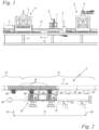
- Fig.1 shows a side view of a section of a packaging machine according to the invention for producing filled bags.
- the packaging machine comprises a machine frame 3, a forming station 4 with a deep-drawing device 5, a filling station 6 with a filling device 7 and a sealing station 8 with a sealing device 9.
- a film web 1 is fed to the packaging machine and deep-drawn in the forming station 4 by means of the deep-drawing device 5, so that troughs are formed in the film web 1. These troughs are filled with a product in the filling station 6.
- a cover film 2 is then fed and in the Sealing station 8 seals the film web 1, closing the filled cavities.
- a cutting station (not shown), the film unit formed in this way is separated into film bags.
- the film web 1 and the cover film 2 are water-soluble films, namely PVOH films, between which a washing or cleaning agent is packaged.
- Filled film bags produced in this way are placed in a dishwasher, for example. There, the film material dissolves on contact with water and releases the detergent contained therein. The same applies to the use of such a film bag in a washing machine.
- the packaging machine comprises a stationary machine frame 3 and a continuously driven conveyor 10.
- the conveyor 10 can be a conveyor belt or the like and in the embodiment shown is formed by plate elements 14 which are connected to one another by articulated chains. Mold cavities 15 (described in more detail below) are provided on the plate elements 14. Fig. 3, 4 ) for deep-drawing the film web 1 and for holding the troughs formed by deep-drawing in the film web 1.
- the plate elements 14 are driven continuously and in rotation around the machine frame 3 together with the conveyor 10, moving on an upper horizontal track in a direction of movement 11 indicated by an arrow for the actual production process of the bags. After the actual production process and after appropriate deflection, they are then returned in the lower area of the machine frame 2 in the opposite direction according to an arrow 12.
- the endless film web 1 is also fed continuously and placed from above on the plate elements 14 with the mold cavities 15. Later, between the filling station 6 and the sealing station 8, the cover film 2 is continuously fed and placed from above on the top of the film web 1.
- the film web 1 and the cover film 2 are moved synchronously and continuously with the conveyor 10 in the direction of movement 11 when placed on.
- the station for feeding the film web 1 and the station for feeding the cover film 2 are mounted in a fixed position on the machine frame 3, as are stations (not shown) for applying water to support the sealing process and for perforating or side-cutting the films.
- the processes carried out here, as well as the movement of the conveyor 10, operate continuously. This is different for the forming station 4, the filling station 6 and the sealing station 8.
- Their deep-drawing device 5, filling device 7 and sealing device 9 are not positioned in a fixed position relative to the machine frame 3, but are moved in sections over a certain distance synchronously with the conveyor 10 in the direction of movement 11.
- the film web 1 is deep-drawn using the moving deep-drawing device 5, in the filling station 6, the product to be packaged is filled into the deep-drawn cavities using the moving filling device 7, and in the sealing station 8, the cover film 2 is sealed onto the lower film web 1 using the moving sealing device 9.
- the deep-drawing device 5, the filling device 7 and the sealing device 9 are cyclically moved back to their starting position, where a new cycle of the respective process begins.
- At least the forming station 4 can also be stationary, for example with a heating roller for heating the film web to deep-drawing temperature.
- Fig.2 shows in an enlarged longitudinal section a section of the deep-drawing device 5 according to Fig.1 .
- the deep-drawing device 5 can be designed to accommodate only a single plate element 14 and to deep-draw the film web 1 there in one cycle.
- the deep-drawing device 5 is designed to accommodate several, here four consecutive plate elements 14 at the same time.
- the four consecutive plate elements 14 mentioned together form a plate set 13, whereby the deep-drawing device 5 always cyclically accommodates a complete plate set 13.
- the filling station 6 and the sealing station 8 are also designed to accommodate and cyclically process a complete plate set 13.
- the information provided in connection with Fig.1 has a mold vacuum device 25.
- This comprises a mold vacuum source 26 and a connecting device 27.
- the connecting device 27 is permanently connected to the mold vacuum source 26 so that a switchable mold vacuum is permanently available in the connecting device 27 during operation.
- the connecting device 27 is provided with at least one vacuum connector 29 on the top side. In the preferred embodiment shown, several, here a total of four, such vacuum connectors 29 are positioned on the top side of the connecting device 27.
- the plate elements 14 each have a mold vacuum connection 28.
- the mold vacuum connections 28 and the vacuum connectors 29 are designed for a cyclical establishment and a cyclical release of the vacuum connection.
- the connecting device 27 with its vacuum connectors 29 is connected in a vacuum-transmitting manner to the mold vacuum connections 28 of an entire plate set 13, i.e. to the mold vacuum connections 28 of a total of four plate elements 14.
- the connecting device 27 with its vacuum connectors 29 is pressed from below against the mold vacuum connections 28 of the plate elements 14 in a sealing manner.
- a mechanical coupling for example with a positive connection or with a latch, can also be useful.
- the connecting device 27 is part of the Fig.1 described in more detail deep-drawing device 5, and is cyclically moved together with this between the start and end positions mentioned above.
- the connecting device 27 runs in the direction of movement 11 synchronously with the plate elements 14 from the start position to the end position.
- the Fig.4 shown mold cavities 15 are subjected to the applied mold vacuum via switching valves 19 also shown there, so that the heated, plastically deformable film web 1 is deep-drawn into the mold cavities 15 by means of the mold vacuum.
- the connecting device 27 with its vacuum connectors 29 is separated from the mold vacuum connections 28 of the connected plate elements 14 and pulled off.
- the mold vacuum connections 28 on the plate elements 14 in use and also the associated vacuum connectors 29 are closed individually automatically or automatically before separation by valves located therein (not shown in detail).
- the aforementioned pulling off takes place vertically downwards.
- a release movement 30 is therefore carried out which separates the vacuum connection with a directional component lying perpendicular to the direction of movement, so that the connecting device 27 is brought to a vertical distance from the plate elements 14.
- connection device 27 which has been released and lowered in this way, now moves back together with the rest of the deep-drawing device 5 in a return movement 31 so far that in a subsequent lifting closing movement 32 it is connected to the following plate set 13' with a directional component that is also perpendicular to the direction of movement 11 and moves along with it again in the direction of movement 11.
- the valves already mentioned in the mold vacuum connections 28 and in the vacuum connectors 29 are automatically opened again, thus restoring a vacuum-transmitting connection.
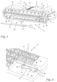
- Fig.3 shows in a perspective principle representation the conveyor 10 after Fig.1 with details on the guidance of the holding vacuum.
- the conveyor 10 is shorter here than in the actual packaging machine according to Fig.1 and only in area of the deep-drawing device 5 in order to better highlight the technical details.
- a matrix of mold cavities 15 is incorporated on the upper sides of the plate elements 14, whereby for the sake of clarity only one plate element 14 with such mold cavities 15 is shown here.
- the film web 1 is placed on the upper side of the plate element 14 moved in the direction of movement 11 and is drawn into the mold cavities 15 in the deep-drawing device 5, which is only indicated here, by means of the device described above in connection with Fig.2 deep-drawn using the vacuum forming device 25 described above.
- the plate elements 14 continue to run in the direction of movement 11 through the subsequent processing stations not shown here, namely through the filling station 6 and the sealing station 8 ( Fig.1 ).
- the mold vacuum no longer acts on the film web 1, but is replaced by a holding vacuum described in more detail below.
- the holding vacuum holds the deep-drawn film web 1 in the mold cavities 15 at least when it passes through the filling station 6 and the sealing station 8 ( Fig.1 ).
- a plate element, marked 14' here, is designed as a connecting element and is provided with at least one, here two vacuum connections 17.
- the plate element 14' is connected to a vacuum source 18 via these vacuum connections 17 in a vacuum-transmitting manner in accordance with the detailed description below.
- the plate element 14' designed as a connecting element corresponds to the other plate elements 14 in its other features and reference numerals.
- All plate elements 14, 14' are permanently connected to a vacuum-transmitting manner by means of connecting lines 16.
- the connecting lines 16 are formed here by flexible hoses. However, they can also be fixed joint channels or the like.
- the vacuum level required by the Vacuum source 18 is fed via the connecting line 24.
- a holding vacuum is fed in, which can be lower than the mold vacuum already mentioned above, but which preferably has the same or at least a similar vacuum level as the mold vacuum.
- the Fig.3 shown deep-drawing arrangement has a vacuum device 20, which in addition to the already mentioned vacuum source 18 also has a longitudinally of the machine frame 3 ( Fig.1 ) guided driver 21 with a rotary feedthrough 22 and a flexible vacuum line 23 between the vacuum source 18 and the driver 21.
- the driver 21 is positioned here to the side next to the rotating chain of plate elements 14, but can be arranged within the orbit of the plate elements 14 or between the pairs of deflection wheels 35, 36 mentioned below.
- the vacuum source 18 is mounted in a stationary manner.
- the flexible vacuum line 23 connected to it is held in a drag chain 38 so that its opposite end connected to the driver 21 can follow the movement of the driver 21.
- a guide rail 38 is mounted to the side next to the conveyor 10 parallel to the direction of movement 11, on which guide rail a carriage in the form of a recirculating ball slide runs.
- the driver 21 with the rotary feedthrough 22 attached to it is mounted on the ball bearing slide 39.
- a rotatable output part of the rotary feedthrough 22 is firmly connected to the plate element 14' designed as a connecting element via a connecting piece 46.
- the conveyor 10 has pairs of deflection wheels 35, 36 at both ends, on which the rotating plate elements 14, 14' are deflected from the upper movement path with the direction of movement 11 into the lower, oppositely moving return path according to the arrow 12 and back again.
- the rotary feedthrough 22 has a rotation axis that is parallel to the rotation axes of the deflection wheels 35, 36.
- the guide rail 38 is dimensioned such that the driver 21 of one deflection wheel 35 to the other deflection wheel 36 and back again.
- the guide rail 38 is positioned such that the rotary union 22 attached to the driver 21 comes to lie coaxially to the one deflection wheel 35 or to the other deflection wheel 36 at its end points of the linear movement.
- the plate element 14' designed as a connection element, is connected to the rotary feedthrough 22 of the vacuum device 20 via at least one, here two, connection lines 24 at its vacuum connections 17.
- the vacuum provided by the vacuum source 18 is thus fed into the plate element 14' via the vacuum line 23, the driver 21, the rotary feedthrough 22 and the connection lines 24. From there, it is distributed to all plate elements 14 via the connecting lines 16, where it is permanently available regardless of their current rotation positions.
- the plate element 14' designed as a connection element is in its rightmost position on the associated deflection wheel 35, so that the driver 21 with the rotary union 22 is also located there.
- the plate element 14' rotates around the axis of rotation of the deflection wheel 35 by the same amount of 180°. Since the rotary union 22 is on the same axis as this, no compensating linear movement is required.
- the rotary union 22 only has the task of allowing the relative rotary movement of the connecting lines 24 relative to the non-rotatable driver 21.
- the rotation of the rotatable output part of the rotary union 22 is brought about by the connecting piece 46. If necessary, the connection by means of the connecting lines 24 can also be sufficient for this, provided they are sufficiently rigid.
- the plate element 14' performs a linear working movement according to the arrow 11, whereby it is moved via the connecting piece 46 takes the driver 21 along the guide rail 38 until it reaches the opposite deflection wheel 36. There, a 180° rotary movement takes place again in an analogous manner. This is followed by a linear movement in the return direction 12, whereby the plate element 14' then takes the driver 21 back to the other deflection wheel 36 via the connecting piece 46 until a complete revolution is achieved. Such a revolution can be repeated as often as desired, whereby all plate elements 14, 14' are permanently supplied with the holding vacuum in the manner described above.
- Fig.4 shows in a partially sectioned perspective view one of the plate elements 14 representative of all other plate elements 14, 14', which are identical in the features shown here.
- the plate element 14 is designed in several parts with a lower carrier plate 33 and with a matrix plate 34 detachably connected to the carrier plate 33.
- the mold cavities 15 are formed in the matrix plate 34.
- the lower carrier plate 33 is connected to the conveyor 10 ( Fig.3 ) so that the die plate 34 can be exchanged, for example for a format change with differently shaped mold cavities 15, without having to detach the carrier plate 33 from the conveyor 10.
- the carrier plate 33 contains the above-mentioned at least one switching valve 19.
- the connecting lines 16, and in the case of the plate element 14' also the connecting lines 24, are connected to the carrier plates 33 of the plate elements 14, 14', so that the plate elements 14, 14' are connected to one another via their carrier plates 33 and the connecting lines 16.
- the switching valve 19 can be an on/off switching valve, whereby several such on/off switching valves can also be provided, for example for the independent activation of a mold vacuum and a holding vacuum.
- the switching valve is designed as a changeover valve for the alternating application of of the mold cavities 15 with the mold vacuum and with the holding vacuum.
- the switching valve 19 comprises a valve body 40 which can be pivoted about a vertical axis and which lies in a corresponding recess in the carrier plate 33.
- the valve body 40 is provided with a valve opening 41 at one end and with a further valve opening 42 at the opposite end.
- the further valve opening 42 is in overlap with the mold vacuum connection 28, while a holding vacuum supply 43 connected to the holding vacuum connection 17 is covered by the valve body 40. Accordingly, in the switching position shown, the mold vacuum is guided via the mold vacuum connection 28, the valve opening 42 in the valve body 40 and via a vacuum channel 44 to the various mold cavities 15, where it can unfold through suction openings 45 in the bottom of the mold cavities 15 and onto the film web 1 ( Fig.3 ) for the deep drawing process.
- the switching valve 19 is switched over, whereby the valve opening 41 is brought into alignment with the holding vacuum supply 43, while at the same time the mold vacuum connection 28 is covered by the valve body 40.
- the holding vacuum from the holding vacuum supply 43 is now fed through the valve opening 41 and the vacuum channel 44 via the suction openings 45 into the mold cavities 15. There, the holding vacuum holds the deep-drawn film troughs in the mold cavities 15.
- Switching between mold vacuum and holding vacuum can be carried out individually for each individual plate element 14, 14'.
- a simple control of the switching valve 19 can be achieved, for example, by switching cams at certain selected positions of the machine frame 3 ( Fig.1 ) by mechanical means.
- other actuations of the switching valves 19 are also conceivable, for example by electrical means.
- a separate supply of deep-drawing vacuum and holding vacuum is provided.
- the vacuum connection 17 is a holding vacuum connection
- the vacuum source 18 is a holding vacuum source
- the vacuum device 20 is a holding vacuum device.
- the plate elements 14, 14' are permanently subjected to the vacuum created by the holding vacuum during operation.
- the supply of deep-drawing vacuum is separate from this.
- a separate supply of deep-drawing vacuum can be provided according to the same concept as the supply of holding vacuum according to the Fig. 3, 4 be provided.
Landscapes
- Engineering & Computer Science (AREA)
- Mechanical Engineering (AREA)
- Manufacturing & Machinery (AREA)
- Blow-Moulding Or Thermoforming Of Plastics Or The Like (AREA)
- Moulds For Moulding Plastics Or The Like (AREA)
Abstract
Description
- Die Erfindung betrifft eine Tiefziehvorrichtung mit den Merkmalen nach dem Oberbegriff des Anspruchs 1 und eine Verpackungsmaschine zur Herstellung von gefüllten Beuteln mit einer solchen Tiefziehvorrichtung.
- In verbreiteter Ausführung werden Verpackungseinheiten häufig dadurch hergestellt, dass zunächst Folien tiefgezogen werden. In die hierbei entstehenden Folienmulden wird ein Produkt eingefüllt, woran anschließend eine Versiegelung mit einer Deckfolie erfolgt. Es entsteht ein doppellagiger Folienstreifen, in dem Teilmengen des Produktes voneinander abgegrenzt sind. Diese Teilmengen werden abschließend in einer Schneidstation vereinzelt.
- Insbesondere im Haushaltsbereich werden in vorgenannter Weise Einzeldosen von Wasch- oder Spülmittel mittels zweier Bahnen von wasserlöslicher Folie verpackt. Für die industrielle Massenfertigung kommen Verpackungsmaschinen in einem kontinuierlichen, nicht getakteten Betrieb zum Einsatz. Hierbei läuft ein Transporteur beispielsweise in Form einer Kette kontinuierlich um ein feststehendes Maschinengestell um, wobei der Transporteur auf der oberen Bearbeitungsseite eine geradlinige, horizontale Wegstrecke zurücklegt. Gemeinsam mit dem Transporteur werden Plattenelemente mit sogenannten Format- bzw. Matrizenplatten kontinuierlich umlaufend mitbewegt. Synchron zur Bewegung der Formatplatten wird eine erste Folienbahn kontinuierlich zugeführt und auf die Oberseite der Formatplatten aufgelegt. In den Formatplatten sind mehrere Formkavitäten ausgeformt, die für den Tiefziehvorgang und auch für den Vorgang des Befüllens eine zentrale Rolle spielen.
- In einer vorbekannten Bauform kommt eine Tiefziehvorrichtung mit einer Formstation zum Einsatz, welche sich nur über eine Teilstrecke synchron mit der jeweiligen Formatplatte von einer Startposition zu einer Endposition mitbewegt und dann zyklisch wieder zurück zur Startposition gefahren wird. Gleichzeitig wird der Transport der Formatplatten und der Folienbahn weiter kontinuierlich aufrechterhalten. Während des Mitlaufens von der Startposition zur Endposition wird die Folienbahn zunächst auf eine solche Temperatur erwärmt, dass sie sich plastisch verformen lässt. Die solchermaßen verformbare Folie wird nun mittels eines aufgebrachten Formvakuums in die Formmulden tiefgezogen. Nach dem Tiefziehen fährt die Formstation zurück zu ihrer Startposition, um dort den nächsten Abschnitt der Folienbahn aufzuheizen und in die Formmulden einer nachfolgenden Formatplatte tiefzuziehen.
- Nach Beendigung des Tiefziehvorgangs muss sichergestellt sein, dass die Folie in den Formmulden verbleibt, um das später einzufüllende Füllgut in ausreichender Menge aufnehmen zu können. Auch beim sich daran anschließenden Siegelvorgang ist es wichtig, dass die untere Folienbahn und die eingefüllten Teilmengen des Produktes an Ort und Stelle verbleiben, um eine saubere und dichte Siegelnaht erzielen zu können. Im Regelfall werden deshalb die Formmulden im Anschluss an den Tiefziehvorgang mit einem Haltevakuum beaufschlagt, welches die Folienbahn in ihrer tiefgezogenen Form hält.
- Um dies zu erreichen, sind im Stand der Technik zweigeteilte Vorrichtungen zur Bereitstellung eines Vakuums bekannt. Ein erster Teil, nämlich eine örtlich feststehende Formvakuumeinrichtung befindet sich dort, wo der Tiefziehvorgang stattfindet. In Bewegungsrichtung nachfolgend befindet sich ebenfalls ortsfest der zweite Teil in Form einer Haltevakuumeinrichtung. In ihrer kontinuierlichen Bewegung gleiten die Formatplatten über beide Teile hinweg und werden über entsprechende Kanalverbindungen sequenziell zunächst mit der Formvakuumeinrichtung und dann mit der Haltevakuumeinrichtung in Verbindung gebracht. Hierüber ist es möglich, die Formmulden zunächst mit einem Formvakuum und anschließend unabhängig davon mit einem geringeren, wenngleich immer noch ausreichend hohen Haltevakuum zu beaufschlagen.
- Im praktischen Betrieb sind einige Schwierigkeiten zu überwinden. Infolge der gleitenden Relativbewegung der Formatplatten relativ zum feststehenden Vakuumkanal müssen entsprechende Dichtmittel zur Verfügung gestellt werden. Trotz des hohen technischen Aufwands können an den Dichtstellen beachtliche Strömungsverluste nicht vermieden werden. Die Einstellung und Beibehaltung eines gewünschten Unterdruckniveaus ist schwierig. Auch die Übergabe von der Formvakuumeinrichtung zur Haltevakuumeinrichtung mit einem kontinuierlichen Unterdruckverlauf gestaltet sich als schwierig.
- Durch die Relativbewegung der Formatplattenelemente gegenüber dem feststehenden Vakuumkanal werden hohe Reibkräfte erzeugt. Diese haben nachteilige Einflüsse auf den Antrieb und die erforderliche Antriebsleistung, auf die Positioniergenauigkeit gegenüber den einzelnen Bearbeitungsstationen beispielsweise in Folge einer Dehnung der Transportkette. Auch die Lebensdauer der Transportkette wird durch die hohen Lasten infolge der zu überwindenden Reibkräfte gemindert.
- All dem steht gegenüber, dass auf Seiten der Anwender der Wunsch nach immer höher werdenden Vakuumwerten aufkommt.
- Der Erfindung liegt die Aufgabe zugrunde, eine gattungsgemäße Tiefziehvorrichtung derart weiterzubilden, dass eine verbesserte Vakuumführung erreicht ist. Diese Aufgabe wird durch eine Tiefziehvorrichtung mit den Merkmalen des Anspruchs 1 gelöst.
- Der Erfindung liegt des Weiteren die Aufgabe zugrunde, eine Verpackungsmaschine zur Herstellung von gefüllten Beuteln hinsichtlich ihrer Wirtschaftlichkeit zu verbessern. Diese Aufgabe wird durch eine Verpackungsmaschine mit den Merkmalen des Anspruchs 8 gelöst.
- Nach der Erfindung ist vorgesehen, dass die Plattenelemente über Verbindungsleitungen dauerhaft miteinander verbunden sind, dass ein Plattenelement als Anschlusselement mit mindestens einem Vakuumanschluss ausgeführt ist, und dass der Vakuumanschluss mit einer Vakuumquelle verbunden ist. Die Plattenelemente sind im Betrieb über die Verbindungsleitungen und den Vakuumanschluss permanent mit dem Vakuum beaufschlagt. Jedes Plattenelement verfügt über ein Schaltventil zur bedarfsabhängigen Aufschaltung des im Plattenelement permanent anliegenden Vakuums auf die zugehörigen Formkavitäten.
- Durch die erfindungsgemäße Ausgestaltung ist ein umlaufendes, geschlossenes Vakuum-Versorgungssystem für das Haltevakuum und/oder für das Formvakuum geschaffen. Durch die geschlossene Bauform ist es einerseits quasi frei von Leckagen. Andererseits müssen bei den Bewegungsvorgängen praktisch keine durch das Vakuumsystem erzeugten Reibungen überwunden werden. Durch das Fehlen von Andrucckräften für die Dichtigkeitserzeugung sind die mechanischen Belastungen insbesondere des Antriebsstranges gering. Verformungen unter Betriebslast sind auf ein Minimum reduziert. Die erforderliche Antriebsleistung ist gering. Das in sich geschlossene Vakuumsystem erlaubt die Bereitstellung von erhöhten Unterdruckwerten, so dass auch schwierige Prozessführungen realisiert werden können.
- Für die Anbindung des umlaufenden, als Anschlusselement ausgeführten Plattenelementes an die Vakuumquelle kommen verschiedene Möglichkeiten in Betracht. Bevorzugt ist eine Vakuumeinrichtung vorgesehen, welche die Vakuumquelle, einen längs des Maschinengestells geführten Mitnehmer mit mindestens einer Drehdurchführung und eine flexible Vakuumumleitung zwischen der Vakuumquelle und dem Mitnehmer umfasst. Der Vakuumanschluss des als Anschlusselement ausgeführten Plattenelementes ist über eine Anschlussleitung mit der Drehdurchführung der Vakuumeinrichtung vakuumübertragend verbunden.
- Für die Bewegung der Einzelkomponenten innerhalb der Vakuumeinrichtung ist kein eigener Antrieb erforderlich. Vielmehr zieht das umlaufende Plattenelement den Mitnehmer entlang seiner Führung in eine Hin- und Herbewegung mit. Die Drehdurchführung erlaubt einerseits das Nachfolgen des entsprechenden Plattenelementes auf seinen linearen Bewegungsbahnen in Prozessrichtung und in rückführender Gegenrichtung. Andererseits erlaubt die Drehdurchführung eine zyklische Drehbewegung des Plattenelements beim zyklischen Umlaufen um das Maschinengestell. Damit ist nur im Bereich der Drehdurchführung die Abdichtung von bewegten, vakuumführenden Teilen erforderlich. Da hier nur eine reine Drehbewegung auftritt, ist eine solche Abdichtung ohne größere Schwierigkeiten realisierbar. Die Leichtgängigkeit der Anordnung ist durch eine solche Abdichtung praktisch nicht beeinträchtigt.
- In einer bevorzugten Ausführungsform sind die Formkavitäten sequentiell mit einem Formvakuum und mit einem Haltevakuum beaufschlagbar, wobei der Vakuumanschluss ein Haltevakuumanschluss ist, wobei die Vakuumquelle eine Haltevakuumquelle ist, und wobei die Plattenelemente im Betrieb permanent mit dem Haltevakuum beaufschlagt sind. In der erfindungsgemäßen Ausgestaltung ist das als Haltevakuum vorgesehene Vakuum entlang der gesamten nutzbaren Bewegungsstrecke der Plattenelemente bereitgestellt. Ohne Zusatzaufwand kann das Haltevakuum an jeder gewünschten Stelle bzw. an jeder Bearbeitungsstation genutzt werden.
- Das in jedem Plattenelement vorhandene Schaltventil erlaubt die Aufschaltung des permanent verfügbaren Vakuums zu jedem gewünschten Zeitpunkt. Ein individuelles Einschalten oder Umschalten einzelner Matrizenplatten von einem Formvakuum auf ein Haltevakuum und umgekehrt ist ohne weiteres möglich.
- Es kann zweckmäßig sein, für das Formvakuum und für das Haltevakuum unterschiedliche und getrennt voneinander betätigbare Schaltventile vorzusehen. In bevorzugter Weiterbildung ist das im jeweiligen Plattenelement vorhandene Schaltventil als Umschaltventil zur wechselseitigen Beaufschlagung der Formkavitäten mit dem Formvakuum und mit dem Haltevakuum ausgeführt. Hierdurch kann bei einfachem Aufbau und hoher Funktionssicherheit insbesondere der Wechsel vom initialen Formvakuum zum nachfolgenden Haltevakuum sichergestellt werden.
- Es kann zweckmäßig sein, mit der vorgenannten Anordnung auch die Einspeisung des Formvakuums vorzunehmen. Anders als beim Haltevakuum muss das Formvakuum jedoch nicht über eine längere Strecke entlang mehrerer Bearbeitungsstationen zur Verfügung stehen. Vielmehr reicht dessen Verfügbarkeit allein im Arbeitsbereich der Tiefziehvorrichtung aus. Bevorzugt weist deshalb die Tiefziehanordnung eine eigene Formvakuumeinrichtung auf, welche eine Formvakuumquelle und eine mit der Formvakuumquelle verbundene Verbindungsvorrichtung umfasst, wobei die Verbindungsvorrichtung Teil der zyklisch bewegten Tiefziehvorrichtung ist. Die Plattenelemente weisen jeweils einen Formvakuumanschluss auf. Korrespondierend dazu weist die Verbindungsvorrichtung mindestens einen Vakuumverbinder auf, welcher zum zyklischen Verbinden mit dem Formvakuumanschluss ausgelegt ist.
- Hiermit ist eine Anordnung geschaffen, bei der die Verbindungsvorrichtung zyklisch mit den übrigen Teilen der Tiefziehvorrichtung zwischen einer Startposition und einer Endposition hin und her verfährt. Bei der Bewegung in Arbeitsrichtung ist die Verbindungsvorrichtung über ihren Vakuumverbinder mit dem zugehörigen Formvakuumanschluss des jeweiligen Plattenelementes verbunden, wobei sie eine verlust- und reibungsfreie Bereitstellung des Formvakuums sicherstellt. Bei der zyklischen Rückbewegung ist die Verbindungsvorrichtung vom Formvakuumanschluss getrennt, so dass die Weiterbewegung der Plattenelemente unbehindert ist. Insbesondere weist dabei die Verbindungsvorrichtung mehrere und vorteilhaft vier Vakuumverbinder zum zyklischen Verbinden mit einer entsprechenden Anzahl von Plattenelementen auf, so dass diese gleichzeitig in einem einzelnen Arbeitstakt mit dem Formvakuum zum gleichzeitigen Tiefziehen beaufschlagt werden können.
- In vorteilhafter Weiterbildung ist die Verbindungsvorrichtung mit ihrem mindestens einen Vakuumverbinder für die Ausführung einer die Vakuumverbindung lösenden Lösebewegung sowie einer die Vakuumverbindung herstellenden Schließbewegung jeweils mit einer senkrecht zur Bewegungsrichtung der Plattenelemente liegenden Richtungskomponente ausgelegt. Durch die entsprechende Lösebewegung wird die Verbindungsvorrichtung auf Abstand zu den bewegten Plattenelementen gebracht, so dass kein mechanischer Kontakt mehr besteht. Die Bewegung der Plattenelemente ist im gelösten Zustand ungehindert. Insbesondere kann sich keine Reibung zwischen der Verbindungsvorrichtung und den bewegten Plattenelementen ausbilden. Durch die verbindende Schließbewegung wird der genannte Abstand wieder aufgehoben. Die Verbindungsvorrichtung dockt vakuumübertragend an ein oder mehrere Plattenelemente an und wird dann synchron mitbewegt. Auch hierbei treten keine Reibkräfte im Zusammenhang mit der Vakuumübertragung auf, so dass insgesamt eine freie Beweglichkeit der Plattenelemente bei gleichzeitig hoher Dichtigkeit der Vakuumführung sichergestellt ist.
- In einer bevorzugten Ausführungsform weisen die Plattenelemente jeweils eine mit dem umlaufenden Transporteur verbundene Trägerplatte und eine lösbar mit der Trägerplatte verbundene Matrizenplatte auf. Die Formkavitäten sind dabei in der Matrizenplatte ausgebildet, während die Trägerplatten über die Verbindungsleitungen miteinander verbunden sind und außerdem jeweils das vorgenannte mindestens eine Schaltventil aufnehmen. Durch Austausch der Matrizenplatte kann mit geringem Aufwand eine Veränderung der Formkavitäten und damit eine Veränderung der Produktgeometrie vorgenommen werden, während die erfindungsgemäße Vakuumführung und -steuerung hiervon unberührt bleibt. Der Aufwand einer Maschinenumrüstung ist dabei auf ein Minimum reduziert.
- Ein Ausführungsbeispiel der Erfindung wird nachfolgend anhand der Zeichnung näher beschrieben. Es zeigen:
- Fig. 1
- in einer seitlichen Ausschnittsdarstellung eine erfindungsgemäß ausgeführte Verpackungsmaschine mit einem kontinuierlich umlaufend bewegten Transporteur sowie mit zyklisch mitbewegten Form-, Füll- und Siegelstationen,
- Fig. 2
- in einer vergrößerten Schnittdarstellung einen Teil der Formstation nach
Fig. 1 mit einer an mehreren Plattenelementen angeschlossenen Verbindungsvorrichtung zur Aufbringung eines Tiefziehvakuums, - Fig. 3
- in einer perspektivischen Prinzipdarstellung den Transporteur nach
Fig. 1 mit untereinander vakuumübertragend verbundenen Plattenelementen und mit einer mitlaufend an ein Anschlusselement angeschlossenen Drehdurchführung einer Haltevakuumeinrichtung, - Fig. 4
- in einer teilweise geschnittenen Perspektivdarstellung eines der Plattenelemente mit Matrizenplatte, mit Trägerplatte und mit in die Trägerplatte integriertem Umschaltventil.
-
Fig. 1 zeigt in einer Seitenansicht einen Ausschnitt aus einer erfindungsgemäßen Verpackungsmaschine zur Herstellung von gefüllten Beuteln. Hierzu umfasst die Verpackungsmaschine ein Maschinengestell 3, eine Formstation 4 mit einer Tiefziehvorrichtung 5, eine Füllstation 6 mit einer Füllvorrichtung 7 und eine Siegelstation 8 mit einer Siegelvorrichtung 9. Eine Folienbahn 1 wird der Verpackungsmaschine zugeführt und in der Formstation 4 mittels der Tiefziehvorrichtung 5 tiefgezogen, so dass sich in der Folienbahn 1 Mulden ausbilden. Diese Mulden werden in der Füllstation 6 mit einem Produkt befüllt. Hieran anschließend wird eine Deckfolie 2 zugeführt und in der Siegelstation 8 auf die Folienbahn 1 aufgesiegelt, wobei die befüllten Mulden verschlossen werden. In einer nicht dargestellten Schneidestation wird die solchermaßen gebildete Folieneinheit zu Folienbeuteln vereinzelt. Im Ausführungsbeispiel handelt es sich bei der Folienbahn 1 und bei der Deckfolie 2 um wasserlösliche Folien, namentlich um PVOH-Folien, zwischen denen ein Wasch- oder Reinigungsmittel verpackt wird. Solchermaßen hergestellte gefüllte Folienbeutel werden beispielsweise in eine Spülmaschine eingelegt. Dort löst sich das Folienmaterial bei Wasserkontakt auf und gibt das enthaltene Spülmittel frei. Sinngemäß das Gleiche gilt für den Einsatz eines solchen Folienbeutels in einer Waschmaschine. - Die Verpackungsmaschine umfasst ein ortsfest montiertes Maschinengestell 3 sowie einen kontinuierlich angetriebenen Transporteur 10. Der Transporteur 10 kann ein Förderband oder dergleichen sein und ist im gezeigten Ausführungsbeispiel durch Plattenelemente 14 gebildet, die durch Gelenkketten miteinander verbunden sind. Auf den Plattenelementen 14 sind weiter unten näher beschriebene Formkavitäten 15 (
Fig. 3, 4 ) zum Tiefziehen der Folienbahn 1 und zum Halten der durch das Tiefziehen geformten Mulden in der Folienbahn 1 ausgebildet. Die Plattenelemente 14 werden zusammen mit dem Transporteur 10 kontinuierlich und um das Maschinengestell 3 umlaufend angetrieben, wobei sie sich für den eigentlichen Herstellvorgang der Beutel auf einer oberen horizontalen Bahn in einer durch einen Pfeil angegebenen Bewegungsrichtung 11 bewegen. Nach dem eigentlichen Herstellvorgang und nach entsprechender Umlenkung werden sie anschließend im unteren Bereich des Maschinengestells 2 in Gegenrichtung entsprechend einem Pfeil 12 zurückgeführt. Ebenso kontinuierlich wird die endlose Folienbahn 1 zugeführt und von oben auf die Plattenelemente 14 mit den Formkavitäten 15 aufgelegt. Zwischen der Füllstation 6 und der Siegelstation 8 wird später noch die Deckfolie 2 kontinuierlich zugeführt und von oben auf die Oberseite der Folienbahn 1 aufgelegt. Die Folienbahn 1 und die Deckfolie 2 werden im aufgelegten Zustand in der Bewegungsrichtung 11 synchron und kontinuierlich mit dem Transporteur 10 mitbewegt. - Die Station zur Zufuhr der Folienbahn 1 sowie die Station zur Zufuhr der Deckfolie 2 sind ortsfest am Maschinengestell 3 montiert, ebenso wie nicht dargestellte Stationen für Wasserauftrag zur Unterstützung des Siegelvorgangs sowie für das Perforieren bzw. seitliche Beschneiden der Folien. Die hier durchgeführten Prozesse arbeiten ebenso wie die Bewegung des Transporteuers 10 kontinuierlich. Anders sieht dies bei der Formstation 4, der Füllstation 6 und der Siegelstation 8 aus. Deren Tiefziehvorrichtung 5, Füllvorrichtung 7 respektive Siegelvorrichtung 9 sind nicht ortsfest relativ zum Maschinengestell 3 positioniert, sondern werden abschnittsweise über eine bestimmte Wegstrecke synchron mit dem Transporteur 10 in der Bewegungsrichtung 11 mitgefahren. Währenddessen erfolgt in der Formstation 4 mittels der mitbewegten Tiefziehvorrichtung 5 das Tiefziehen der Folienbahn 1, in der Füllstation 6 mittels der mitbewegten Füllvorrichtung 7 das Einfüllen des zu verpackenden Produkts in die tiefgezogenen Mulden, und in der Siegelstation 8 mittels der mitbewegten Siegelvorrichtung 9 das Aufsiegeln der Deckfolie 2 auf die untere Folienbahn 1. Nach Beendigung des jeweiligen Vorganges werden die Tiefziehvorrichtung 5, die Füllvorrichtung 7 und die Siegelvorrichtung 9 zyklisch wieder zurück auf ihre Ausgangsposition verfahren, wo dann ein neuer Zyklus des jeweils ausgeführten Prozesses beginnt. Zumindest die Formstation 4 kann aber auch ortsfest beispielsweise mit einer Heizwalze für die Erwärmung der Folienbahn auf Tiefziehtemperatur sein.
-
Fig. 2 zeigt in einer vergrößerten Längsschnittdarstellung einen Ausschnitt aus der Tiefziehvorrichtung 5 nachFig. 1 . Die Tiefziehvorrichtung 5 kann dazu ausgelegt sein, nur ein einzelnes Plattenelement 14 aufzunehmen und dort die Folienbahn 1 in einem Zyklus tiefzuziehen. Im gezeigten Ausführungsbeispiel ist die Tiefziehvorrichtung 5 zur gleichzeitigen Aufnahme von mehreren, hier vier aufeinanderfolgenden Plattenelementen 14 ausgelegt. Die genannten vier aufeinanderfolgenden Plattenelemente 14 bilden zusammen einen Plattensatz 13, wobei die Tiefziehvorrichtung 5 zyklisch immer einen vollständigen Plattensatz 13 aufnimmt. Dies muss nicht zwingend auch für die nachfolgenden Füll- und Siegelstationen 6, 8 (Fig. 1 ) gelten. Im gezeigten Ausführungsbeispiel nachFig. 1 sind jedoch auch die Füllstation 6 und die Siegelstation 8 zur Aufnahme und zyklischen Prozessierung eines kompletten Plattensatzes 13 ausgelegt. - Die im Zusammenhang mit
Fig. 1 schon beschriebene und hier nur ausschnittsweise dargestellte Tiefziehanordnung weist eine Formvakuumeinrichtung 25 auf. Diese umfasst eine Formvakuumquelle 26 und eine Verbindungsvorrichtung 27. Die Verbindungsvorrichtung 27 ist dauerhaft mit der Formvakuumquelle 26 verbunden, so dass während des Betriebes in der Verbindungsvorrichtung 27 permanent ein schaltbares Formvakuum zur Verfügung steht. An der Oberseite ist die Verbindungsvorrichtung 27 mit mindestens einem Vakuumverbinder 29 versehen. Im gezeigten bevorzugten Ausführungsbeispiel sind mehrere, hier insgesamt vier solcher Vakuumverbinder 29 an der Oberseite der Verbindungsvorrichtung 27 positioniert. - Auf ihrer jeweiligen Unterseite weisen die Plattenelemente 14 jeweils einen Formvakuumanschluss 28 auf. Die Formvakuumanschlüsse 28 und die Vakuumverbinder 29 sind zu einem zyklischen Herstellen und zu einem zyklischen Lösen der Vakuumverbindung ausgelegt. In der Darstellung nach
Fig. 2 ist die Verbindungsvorrichtung 27 mit ihren Vakuumverbindern 29 vakuumübertragend mit den Formvakuumanschlüssen 28 eines gesamten Plattensatzes 13, also mit den Formvakuumanschlüssen 28 von insgesamt vier Plattenelementen 14 verbunden. In diesem angeschlossenen Zustand ist die Verbindungsvorrichtung 27 mit ihren Vakuumverbindern 29 dichtend von unten gegen die Formvakuumanschlüsse 28 der Plattenelemente 14 gedrückt. Es kann aber auch eine mechanische Kupplung beispielsweise mit Formschluss bzw. mit Verrastung zweckmäßig sein. Jedenfalls herrscht im angeschlossenen Zustand eine druckdichte, vakuumübertragende Verbindung zwischen der Verbindungsvorrichtung 27 und den angeschlossenen Plattenelementen 14. - Die Verbindungsvorrichtung 27 ist Teil der im Zusammenhang mit
Fig. 1 näher beschriebenen Tiefziehvorrichtung 5, und wird gemeinsam mit dieser zyklisch zwischen den weiter ober schon erwähnten Start- und Endpositionen hin und her bewegt. Im verbundenen Zustand nachFig. 2 läuft die Verbindungsvorrichtung 27 in der Bewegungsrichtung 11 synchron mit den Plattenelementen 14 von der Startposition bis zur Endposition mit. Währenddessen werden die inFig. 4 gezeigten Formkavitäten 15 über ebenfalls dort gezeigten Schaltventile 19 mit dem anliegenden Formvakuum beaufschlagt, so dass die erwärmte, plastisch verformbare Folienbahn 1 mittels des Formvakuums in die Formkavitäten 15 tiefgezogen wird. - Nach Beendigung des Tiefziehvorgangs und bei Erreichen der Endposition wird die Verbindungsvorrichtung 27 mit ihren Vakuumverbindern 29 von den Formvakuumanschlüssen 28 der angeschlossenen Plattenelemente 14 getrennt und davon abgezogen. Die Formvakuumanschlüsse 28 an den im Einsatz befindlichen Plattenelementen 14 und auch die zugehörigen Vakuumverbinder 29 werden vor dem Trennen durch darin befindliche, nicht näher dargestellte Ventile einzeln automatisch bzw. selbsttätig verschlossen. Das genannte Abziehen erfolgt vertikal nach unten. Es wird also eine die Vakuumverbindung trennende Lösebewegung 30 mit einer senkrecht zur Bewegungsrichtung liegenden Richtungskomponente ausgeführt, so dass die Anschlussvorrichtung 27 auf einem vertikalen Abstand zu den Plattenelementen 14 gebracht wird. Die solchermaßen gelöste und abgesenkte Anschlussvorrichtung 27 fährt nun gemeinsam mit der übrigen Tiefziehvorrichtung 5 in einer Rückbewegung 31 so weit zurück, dass es in einer anschließenden, anhebenden Schließbewegung 32 mit einer ebenfalls senkrecht zur Bewegungsrichtung 11 liegenden Richtungskomponente an den nachfolgenden Plattensatz 13' angeschlossen wird und mit diesem in der Bewegungsrichtung 11 erneut mitfährt. Beim Anschließen bzw. Verbinden werden die schon genannten Ventile in den Formvakuumanschlüssen 28 und in den Vakuumverbindern 29 wieder selbsttätig geöffnet, womit eine vakuumübertragende Verbindung wiederhergestellt ist.
-
Fig. 3 zeigt in einer perspektivischen Prinzipdarstellung den Transporteur 10 nachFig. 1 mit Einzelheiten zur Führung des Haltevakuums. Der Transporteur 10 ist hier zur Vereinfachung kürzer als in der tatsächlichen Verpackungsmaschine nachFig. 1 und nur im Bereich der Tiefziehvorrichtung 5 dargestellt, um die technischen Einzelheiten besser hervorheben zu können. - Es ist hier erkennbar, dass auf den Oberseiten der Plattenelemente 14 eine Matrix von Formkavitäten 15 eingearbeitet ist, wobei der besseren Übersicht halber hier nur ein Plattenelement 14 mit solchen Formkavitäten 15 dargestellt ist. Wie schon im Zusammenhang mit
Fig. 1 erläutert wird die Folienbahn 1 im Betrieb auf die Oberseite der in der Bewegungsrichtung 11 bewegten Plattenelement 14 aufgelegt und in der hier nur angedeuteten Tiefziehvorrichtung 5 in die Formkavitäten 15 mittels der weiter oben im Zusammenhang mitFig. 2 beschriebenen Formvakuumeinrichtung 25 tiefgezogen. Nach Abschluss des Tiefziehvorgangs laufen die Plattenelemente 14 in der Bewegungsrichtung 11 weiter durch die nachfolgenden, hier nicht dargestellten Bearbeitungsstationen, namentlich durch die Füllstation 6 und die Siegelstation 8 (Fig. 1 ). Das Formvakuum wirkt hierbei nicht mehr auf die Folienbahn 1 ein, wird aber durch ein nachfolgend näher beschriebenes Haltevakuum ersetzt. Das Haltevakuum hält die tiefgezogene Folienbahn 1 in den Formkavitäten 15 zumindest beim Durchlauf durch die Füllstation 6 und die Siegelstation 8 (Fig. 1 ). - Für die Beaufschlagung der Formkavitäten 15 mit dem genannten Haltevakuum ist ein hier mit 14' gekennzeichnetes Plattenelement als Anschlusselement ausgeführt und mit mindestens einem, hier mit zwei Vakuumanschlüssen 17 versehen. Über diese Vakuumanschlüsse 17 ist das Plattenelement 14' vakuumübertragend mit einer Vakuumquelle 18 entsprechend der nachfolgenden näheren Beschreibung verbunden. Darüber hinaus entspricht das als Anschlusselement ausgeführte Plattenelement 14' in seinen übrigen Merkmalen und Bezugszeichen den anderen Plattenelementen 14. Sämtliche Plattenelemente 14, 14' sind mittels Verbindungsleitungen 16 dauerhaft vakuumübertragend verbunden. Die Verbindungsleitungen 16 sind hier durch flexible Schläuche gebildet. Es kann sich aber auch um feste Gelenkkanäle oder dergleichen handeln. Jedenfalls ist im Betrieb über die Verbindungsleitungen 16 in sämtlichen Plattenelementen 14, 14' an jeder Position ihres Umlaufs dasjenige Vakuumniveau verfügbar ist, das von der Vakuumquelle 18 über die Anschlussleitung 24 eingespeist wird. Im praktischen Betrieb wird ein Haltevakuum eingespeist, welches geringer sein kann als das vorstehend schon erwähnte Formvakuum, welches aber bevorzugt ein gleiches, zumindest jedoch ein ähnliches Vakuumniveau hat wie das Formvakuum.
- Für die konkrete Ausgestaltung der Haltevakuumversorgung weist die hier in
Fig. 3 gezeigte Tiefziehanordnung eine Vakuumeinrichtung 20 auf, welche neben der schon erwähnten Vakuumquelle 18 noch einen längs des Maschinengestells 3 (Fig. 1 ) geführten Mitnehmer 21 mit einer Drehdurchführung 22 sowie eine flexible Vakuumleitung 23 zwischen der Vakuumquelle 18 und dem Mitnehmer 21 umfasst. Der Mitnehmer 21 ist hier seitlich neben der umlaufenden Kette aus Plattenelementen 14 positioniert, kann aber innerhalb der Umlaufbahn der Plattenelemente 14 bzw. zwischen den weiter unten noch erwähnten Paaren von Umlenkrädern 35, 36 verlaufend angeordnet sein. Das Gleiche gilt auch für die Verbindungsleitungen 16. Die Vakuumquelle 18 ist ortsfest montiert. Die an ihre angeschlossene flexible Vakuumleitung 23 ist in einer Schleppkette 38 gehalten, so dass ihr gegenüberliegendes, an den Mitnehmer 21 angeschlossenes Ende der Bewegung des Mitnehmers 21 folgen kann. Für die Längsbewegung des Mitnehmers 21 ist seitlich neben dem Transporteur 10 parallel zur Bewegungsrichtung 11 eine Führungsschiene 38 montiert, auf der ein Schlitten in Form eines Kugelumlaufschlittens läuft. Auf dem Kugelumlaufschlitten 39 ist der Mitnehmer 21 mit der daran befestigten Drehdurchführung 22 montiert. Ein drehbarer Ausgangsteil der Drehdurchführung 22 ist über ein Verbindungsstück 46 fest mit dem als Anschlusselement ausgeführten Plattenelement 14' verbunden. - Der Transporteur 10 weist an seinen beiden Enden Paare von Umlenkrädern 35, 36 auf, an denen die umlaufenden Plattenelemente 14, 14' von der oberen Bewegungsstrecke mit der Bewegungsrichtung 11 in die untere, entgegengesetzt bewegte Rücklaufstrecke entsprechend dem Pfeil 12 und wieder zurück umgelenkt werden. Die Drehdurchführung 22 weist eine Drehachse auf, die parallel zu den Drehachsen der Umlenkräder 35, 36 liegt. Die Führungsschiene 38 ist derart bemessen, dass der Mitnehmer 21 von einem Umlenkrad 35 zum anderen Umlenkrad 36 und wieder zurück hin und her verfahren kann. Außerdem ist die Führungsschiene 38 derart positioniert, dass die am Mitnehmer 21 befestigte Drehdurchführung 22 an ihren Endpunkten der linearen Bewegung koaxial zu dem einen Umlenkrad 35 respektive zu dem anderen Umlenkrad 36 zu liegen kommt.
- Das als Anschlusselement ausgeführte Plattenelement 14' ist an seinen Vakuumanschlüssen 17 über mindestens eine, hier über zwei Anschlussleitungen 24 mit der Drehdurchführung 22 der Vakuumeinrichtung 20 vakuumübertragend verbunden. Das von der Vakuumquelle 18 bereitgestellte Vakuum wird also durch die Vakuumleitung 23, dem Mitnehmer 21, die Drehdurchführung 22 und die Anschlussleitungen 24 in das Plattenelement 14' eingespeist. Von dort wird es über die Verbindungsleitungen 16 auf sämtliche Plattenelemente 14 verteilt, wo es unabhängig von deren aktuellen Umlaufpositionen permanent zur Verfügung steht.
- In der Darstellung nach
Fig. 3 befindet sich das als Anschlusselement ausgeführte Plattenelement 14' in seiner äußerst rechten Position auf dem zugehörigen Umlenkrad 35, so dass sich auch dort der Mitnehmer 21 mit der Drehdurchführung 22 befindet. Während seines 180°-Umlaufs dreht sich das Plattenelement 14' um die Drehachse des Umlenkrades 35 mit dem gleichen Betrag von 180°. Da sich die Drehdurchführung 22 achsgleich hierzu befindet, ist keine ausgleichende Linearbewegung erforderlich. Die Drehdurchführung 22 hat hier lediglich die Aufgabe, die relative Drehbewegung der Anschlussleitungen 24 relativ zum nicht drehbar gehaltenen Mitnehmer 21 zuzulassen. Die Drehung des drehbaren Ausgangsteils der Drehdurchführung 22 wird durch das Verbindungsstück 46 herbeigeführt. Gegebenenfalls kann hierfür aber auch die Anbindung mittels der Anschlussleitungen 24 ausreichen, sofern diese ausreichend steif sind. - Im Anschluss an die genannte Drehbewegung führt das Plattenelement 14' eine lineare Arbeitsbewegung entsprechend dem Pfeil 11 aus, wobei es über das Verbindungsstück 46 den Mitnehmer 21 entlang der Führungsschiene 38 bis zum Erreichen des gegenüberliegenden Umlenkrades 36 mitnimmt. Dort findet erneut eine 180°-Drehbewegung in analoger Weise statt. Hieran schließt sich wieder eine lineare Bewegung in der Rückführungsrichtung 12 an, wobei dann das Plattenelement 14' den Mitnehmer 21 über das Verbindungsstück 46 wieder zurück zum anderen Umlenkrad 36 mitnimmt, bis ein vollständiger Umlauf erzielt ist. Ein solcher Umlauf kann beliebig oft wiederholt werden, wobei sämtliche Plattenelemente 14, 14' in vorstehend beschriebener Weise dauerhaft mit dem Haltevakuum versorgt sind.
-
Fig. 4 zeigt in einer teilweise geschnittenen Perspektivdarstellung eines der Plattenelemente 14 stellvertretend für alle übrigen Plattenelemente 14, 14', welche in den hier gezeigten Merkmalen identisch ausgeführt sind. Demnach ist das Plattenelement 14 mehrteilig mit einer unteren Trägerplatte 33 und mit einer lösbar mit der Trägerplatte 33 verbundenen Matrizenplatte 34 ausgeführt. In der Matrizenplatte 34 sind die Formkavitäten 15 ausgebildet. Die untere Trägerplatte 33 ist mit dem Transporteur 10 (Fig. 3 ) verbunden, so dass die Matrizenplatte 34 beispielsweise für einen Formatwechsel mit unterschiedlich geformten Formkavitäten 15 ausgetauscht werden kann, ohne die Trägerplatte 33 vom Transporteur 10 lösen zu müssen. - Die Trägerplatte 33 beinhaltet das oben schon erwähnte mindestens eine Schaltventil 19. Außerdem ergibt sich aus der Zusammenschau mit
Fig. 3 , dass die Verbindungsleitungen 16, im Falle des Plattenelementes 14' auch die Anschlussleitungen 24 an den Trägerplatten 33 der Plattenelemente 14, 14' angeschlossen sind, so dass also die Plattenelemente 14, 14' über ihre Trägerplatten 33 und die Verbindungsleitungen 16 miteinander verbunden sind. - Das Schaltventil 19 kann ein Ein-/Aus-Schaltventil sein, wobei auch mehrere solcher Ein-/Aus-Schaltventile beispielsweise zur unabhängigen Aufschaltung eines Formvakuums und eines Haltevakuums vorgesehen sein können. Im gezeigten Ausführungsbeispiel ist das Schaltventil hier als Umschaltventil zur wechselseitigen Beaufschlagung der Formkavitäten 15 mit dem Formvakuum und mit dem Haltevakuum ausgeführt. Hierzu umfasst das Schaltventil 19 einen um eine Hochachse schwenkbaren Ventilkörper 40, der in einer entsprechenden Aussparung in der Trägerplatte 33 liegt. Der Ventilkörper 40 ist an einem Ende mit einer Ventilöffnung 41 und am gegenüberliegenden Ende mit einer weiteren Ventilöffnung 42 versehen. In der gezeigten Schaltposition liegt die weitere Ventilöffnung 42 in Überdeckung mit dem Formvakuumanschluss 28, während eine mit dem Haltevakuumanschluss 17 in Verbindung stehende Haltevakuumzufuhr 43 durch den Ventilkörper 40 abgedeckt ist. Demnach wird in der gezeigten Schaltstellung das Formvakuum über den Formvakuumanschluss 28, die Ventilöffnung 42 im Ventilkörper 40 und über einen Vakuumkanal 44 zu den verschiedenen Formkavitäten 15 geleitet, wo es durch Saugöffnungen 45 im Boden der Formkavitäten 15 sich entfalten und auf die Folienbahn 1 (
Fig. 3 ) für den Tiefziehvorgang einwirken kann. - Nach Beendigung des Tiefziehens wird das Schaltventil 19 umgeschaltet, wobei die Ventilöffnung 41 in Überdeckung mit der Haltevakuumzufuhr 43 gebracht wird, während zeitgleich der Formvakuumanschluss 28 durch den Ventilkörper 40 abgedeckt wird. Anstelle des Formvakuums wird also nun das Haltevakuum aus der Haltevakuumzufuhr 43 durch die Ventilöffnung 41 und den Vakuumkanal 44 über die Saugöffnungen 45 in die Formkavitäten 15 eingespeist. Dort hält das Haltevakuum die tiefgezogenen Folienmulden in den Formkavitäten 15.
- Das Umschalten zwischen Formvakuum und Haltevakuum kann individuell für jedes einzelne Plattenelement 14, 14' vorgenommen werden. Eine einfache Steuerung des Schaltventils 19 kann beispielsweise durch Schaltnocken an bestimmten gewählten Positionen des Maschinengestells 3 (
Fig. 1 ) auf mechanischem Wege erfolgen. Denkbar sind aber auch andere Betätigungen der Schaltventile 19, beispielsweise auf elektrischem Weg. - Insbesondere dann, wenn das Tiefziehvakuum und das Haltevakuum das gleiche Niveau aufweisen sollen, kann eine Beschränkung der Vakuumanordnung auf die Ausführung nach den
Fig. 3 und 4 erfolgen, während auf das Tiefziehvakuumkonzept nachFig. 2 verzichtet werden kann. Das über die Anordnung nach denFig. 3 und 4 bereitgestellte Vakuum kann sowohl als Tiefziehvakuum als auch als Haltevakuum genutzt werden. - Im gezeigten Ausführungsbeispiel ist jedoch eine getrennte Versorgung mit Tiefziehvakuum und mit Haltevakuum vorgesehen. Hierbei ist nach den
Fig. 3, 4 der Vakuumanschluss 17 ein Haltevakuumanschluss, die Vakuumquelle 18 eine Haltevakuumquelle und Vakuumeinrichtung 20 eine Haltevakuumeinrichtung. Die Plattenelemente 14, 14' sind dabei im Betrieb permanent mit dem Haltevakuum ausgebildeten Vakuum beaufschlagt. Getrennt davon ist die Versorgung mit Tiefziehvakuum nachFig. 2 vorgesehen. Alternativ dazu kann aber auch eine getrennte Versorgung mit Tiefziehvakuum nach dem gleichen Konzept wie die Versorgung mit Haltevakuum nach denFig. 3, 4 vorgesehen sein.
Claims (9)
- Tiefziehanordnung zum Tiefziehen einer kontinuierlich zugeführten Folienbahn (1), umfassend einen kontinuierlich um ein feststehendes Maschinengestell (3) umlaufenden Transporteur (10) mit Plattenelementen (14, 14') und mit in den Plattenelementen (14, 14') befindlichen Formkavitäten (15), des Weiteren umfassend eine zyklisch getaktete, von einer Startposition zu einer Endposition mit dem Transporteur (10) mitlaufende und von dort zur Startposition zurücklaufende Tiefziehvorrichtung (5), wobei die Formkavitäten (15) mit einem Vakuum beaufschlagbar sind,
dadurch gekennzeichnet, dass die Plattenelemente (14, 14') über Verbindungsleitungen (16) dauerhaft miteinander verbunden sind, dass ein Plattenelement (14') als Anschlusselement mit mindestens einem Vakuumanschluss (17) ausgeführt ist, dass der Vakuumanschluss (17) mit einer Vakuumquelle (18) verbunden ist, dass die Plattenelemente (14, 14') im Betrieb über die Verbindungsleitungen (16) und den Vakuumanschluss (17) permanent mit dem Vakuum beaufschlagt sind, und dass jedes Plattenelement (14, 14') über mindestens ein Schaltventil (19) zur bedarfsabhängigen Aufschaltung des im Plattenelement (14, 14') permanent anliegenden Vakuums auf die zugehörigen Formkavitäten (15) verfügt. - Tiefziehanordnung nach Anspruch 1,
dadurch gekennzeichnet, dass die Tiefziehanordnung eine Vakuumeinrichtung (20) aufweist, welche die Vakuumquelle (18), einen längs des Maschinengestells (3) geführten Mitnehmer (21) mit mindestens einer Drehdurchführung (22), und eine flexible Vakuumleitung (23) zwischen der Vakuumquelle (18) und dem Mitnehmer (21) umfasst, wobei der Vakuumanschluss (17) des als Anschlusselement ausgeführten Plattenelements (14') über eine Anschlussleitung (24) mit der Drehdurchführung (22) der Vakuumeinrichtung (20) vakuumübertragend verbunden ist. - Tiefziehanordnung nach Anspruch 1 oder 2,
dadurch gekennzeichnet, dass die Formkavitäten (15) sequentiell mit einem Formvakuum und mit einem Haltevakuum beaufschlagbar sind, wobei der Vakuumanschluss (17) ein Haltevakuumanschluss ist, wobei die Vakuumquelle (18) eine Haltevakuumquelle ist, und wobei die Plattenelemente (14, 14') im Betrieb permanent mit dem Haltevakuum beaufschlagt sind. - Tiefziehanordnung nach Anspruch 3,
dadurch gekennzeichnet, dass das Schaltventil (19) als Umschaltventil zur wechselseitigen Beaufschlagung der Formkavitäten (15) mit dem Formvakuum und mit dem Haltevakuum ausgeführt ist. - Tiefziehanordnung nach Anspruch 3 oder 4,
dadurch gekennzeichnet, dass die Tiefziehanordnung eine Formvakuumeinrichtung (25) aufweist, welche eine Formvakuumquelle (26) und eine mit der Formvakuumquelle (26) verbundene Verbindungsvorrichtung (27) umfasst, wobei die Verbindungsvorrichtung (27) Teil der zyklisch bewegten Tiefziehvorrichtung (5) ist, wobei die Plattenelemente (14) jeweils einen Formvakuumanschluss (28) aufweisen, und wobei die Verbindungsvorrichtung (27) mindestens einen Vakuumverbinder (29) aufweist, welcher zum zyklischen Verbinden mit dem Formvakuumanschluss (28) ausgelegt ist. - Tiefziehanordnung nach Anspruch 5,
dadurch gekennzeichnet, dass die Verbindungsvorrichtung (27) mehrere und insbesondere vier Vakuumverbinder (29) zum zyklischen Verbinden mit einer entsprechenden Anzahl von Plattenelementen (14) aufweist. - Tiefziehanordnung nach Anspruch 5 oder 6,
dadurch gekennzeichnet, dass die Plattenelemente (14) im Bereich der Formstation (8) in einer Bewegungsrichtung (11) bewegt werden, wobei die Verbindungsvorrichtung (27) mit ihrem mindestens einen Vakuumverbinder (29) für die Ausführung einer die Vakuumverbindung lösenden Lösebewegung (30) sowie einer die Vakuumverbindung herstellenden Schließbewegung (32) jeweils mit einer senkrecht zur Bewegungsrichtung (11) liegenden Richtungskomponente ausgelegt ist. - Tiefziehanordnung nach einem der Ansprüche 1 bis 7,
dadurch gekennzeichnet, dass die Plattenelemente (14) jeweils eine mit dem umlaufenden Transporteur (10) verbundene Trägerplatte (33) und eine lösbar mit der Trägerplatte (33) verbundene Matrizenplatte (34) aufweist, wobei die Formkavitäten (15) in der Matrizenplatte (34) ausgebildet sind, wobei die Trägerplatten (33) über die Verbindungleitungen (16) miteinander verbunden sind, und wobei die Trägerplatten (33) das Schaltventil (19) aufnehmen. - Verpackungsmaschine zur Herstellung von gefüllten Beuteln, umfassend eine Tiefziehanordnung nach einem der Ansprüche 1 bis 8, des Weiteren umfassend nachfolgende Bearbeitungsstationen, insbesondere eine Füllstation (6) und eine Siegelstation (8).
Priority Applications (4)
| Application Number | Priority Date | Filing Date | Title |
|---|---|---|---|
| PL22200790.8T PL4353444T3 (pl) | 2022-10-11 | 2022-10-11 | Urządzenie do głębokiego tłoczenia i maszyna pakująca z urządzeniem do głębokiego tłoczenia |
| EP22200790.8A EP4353444B1 (de) | 2022-10-11 | 2022-10-11 | Tiefziehvorrichtung und verpackungsmaschine mit einer tiefziehvorrichtung |
| ES22200790T ES3041485T3 (en) | 2022-10-11 | 2022-10-11 | Deep drawing device and packaging machine with a deep drawing device |
| US18/483,327 US12208563B2 (en) | 2022-10-11 | 2023-10-09 | Deep-drawing apparatus and packaging machine having a deep-drawing apparatus |
Applications Claiming Priority (1)
| Application Number | Priority Date | Filing Date | Title |
|---|---|---|---|
| EP22200790.8A EP4353444B1 (de) | 2022-10-11 | 2022-10-11 | Tiefziehvorrichtung und verpackungsmaschine mit einer tiefziehvorrichtung |
Publications (2)
| Publication Number | Publication Date |
|---|---|
| EP4353444A1 true EP4353444A1 (de) | 2024-04-17 |
| EP4353444B1 EP4353444B1 (de) | 2025-08-20 |
Family
ID=83690310
Family Applications (1)
| Application Number | Title | Priority Date | Filing Date |
|---|---|---|---|
| EP22200790.8A Active EP4353444B1 (de) | 2022-10-11 | 2022-10-11 | Tiefziehvorrichtung und verpackungsmaschine mit einer tiefziehvorrichtung |
Country Status (4)
| Country | Link |
|---|---|
| US (1) | US12208563B2 (de) |
| EP (1) | EP4353444B1 (de) |
| ES (1) | ES3041485T3 (de) |
| PL (1) | PL4353444T3 (de) |
Citations (2)
| Publication number | Priority date | Publication date | Assignee | Title |
|---|---|---|---|---|
| DE2046328A1 (de) * | 1969-09-23 | 1971-05-27 | Bp Chem Int Ltd | Formmaschine zur Herstellung von Gegen standen aus plastisch verformbaren Material platten |
| US3837782A (en) * | 1971-12-15 | 1974-09-24 | Filper Corp | Apparatus for forming containers |
Family Cites Families (5)
| Publication number | Priority date | Publication date | Assignee | Title |
|---|---|---|---|---|
| US3347011A (en) * | 1964-02-04 | 1967-10-17 | Royal Package Equipment Inc | Packaging machine and method of forming packages |
| US3920371A (en) * | 1974-03-14 | 1975-11-18 | Hoerner Waldorf Corp | Apparatus for forming visual display packages |
| ATE52058T1 (de) * | 1983-10-06 | 1990-05-15 | Servichem Ag | Vorrichtung zur herstellung von gegenstaenden aus einer materialbahn einer thermoplastischen folie und die verwendung derselben zur herstellung von behaelterteilen. |
| US5773540A (en) * | 1996-04-16 | 1998-06-30 | Irwin Research And Development, Inc. | Mold assembly for thermo-forming machine |
| DE60204133T2 (de) * | 2002-06-28 | 2006-02-23 | The Procter & Gamble Company, Cincinnati | Verfahren und Vorrichtung zur Herstellung von Beuteln |
-
2022
- 2022-10-11 ES ES22200790T patent/ES3041485T3/es active Active
- 2022-10-11 PL PL22200790.8T patent/PL4353444T3/pl unknown
- 2022-10-11 EP EP22200790.8A patent/EP4353444B1/de active Active
-
2023
- 2023-10-09 US US18/483,327 patent/US12208563B2/en active Active
Patent Citations (2)
| Publication number | Priority date | Publication date | Assignee | Title |
|---|---|---|---|---|
| DE2046328A1 (de) * | 1969-09-23 | 1971-05-27 | Bp Chem Int Ltd | Formmaschine zur Herstellung von Gegen standen aus plastisch verformbaren Material platten |
| US3837782A (en) * | 1971-12-15 | 1974-09-24 | Filper Corp | Apparatus for forming containers |
Also Published As
| Publication number | Publication date |
|---|---|
| EP4353444B1 (de) | 2025-08-20 |
| US20240116237A1 (en) | 2024-04-11 |
| PL4353444T3 (pl) | 2025-12-22 |
| US12208563B2 (en) | 2025-01-28 |
| ES3041485T3 (en) | 2025-11-12 |
Similar Documents
| Publication | Publication Date | Title |
|---|---|---|
| DE60310801T2 (de) | Vorrichtung zur Herstellung von Behältern aus mehrschichtiger Folie mit texturierter Oberfläche für das Aufbewahren von soliden Reinigungsmitteln | |
| DE1953727A1 (de) | Verpackungsmaschine | |
| EP3875246B1 (de) | Tiefziehvorrichtung, verpackungsmaschine mit einer tiefziehvorrichtung und verfahren zum betrieb der tiefziehvorrichtung | |
| DE2127160B2 (de) | Vorrichtung zum schneiden von tafeln | |
| DE1786112A1 (de) | Verschliessmaschine zur Herstellung aufeinanderfolgender,getrennter,quer verlaufender Schweissnaehte zwischen den Lagen einer Mehrlagenbahn in einer Verpackungsmaschine | |
| DE2556125A1 (de) | Verfahren und vorrichtung zur kontinuierlichen und pyrogenfreien herstellung von mit anschlussnippeln versehenen kunststoffbeuteln | |
| EP0413927B1 (de) | Vorrichtung zur Herstellung einer Flüssigkeitspackung | |
| DE2442858C3 (de) | Maschine zum Formen von rohrförmigen Kartons | |
| DE2702928A1 (de) | Verfahren und einrichtung zur herstellung gefuellter verpackungsbehaelter | |
| DE4313325C2 (de) | Vorrichtung zum Füllen und Verschließen von Packungen | |
| DE3209595A1 (de) | Maschine zum abfuellen und verpacken von nahrungsmitteln | |
| DE2633341A1 (de) | Vorrichtung zur herstellung von kunststoffbeuteln mit anschlusstutzen | |
| DE102018002280A1 (de) | Endlos umlaufende Behälter-Fördervorrichtung in einer Verpackungsmaschine | |
| EP2447169A2 (de) | Schalenverschließmaschine und Verfahren zum Betrieb einer solchen Schalenverschließmaschine | |
| EP3269539B1 (de) | Vorrichtung zum öffnen eines endbereichs eines schlauchförmigen sackkörpers | |
| EP4353444B1 (de) | Tiefziehvorrichtung und verpackungsmaschine mit einer tiefziehvorrichtung | |
| EP1466829A1 (de) | Anlage zum Füllen von Ventilsäcken | |
| EP1028057B1 (de) | Füllstation einer aseptischen Maschine zum Formen, Füllen und Schliessen von Verpackungen | |
| DE4037254C2 (de) | ||
| EP2977325A1 (de) | Schalenverschließmaschine mit Seitenbeladung und Verfahren zum Aufbringen einer Folie | |
| EP4219124A1 (de) | Folientransportplatte und folientransportsystem | |
| EP3452277B1 (de) | Transporteinrichtung und verfahren zum transport von säcken oder beuteln sowie vorrichtung zur herstellung von säcken oder beuteln | |
| DE69715685T2 (de) | SCHWEISS-SCHNEID-EINRICHTUNG FüR KONTINUIERLICH ARBEITENDE VERPACKUNGSMASCHINEN | |
| DE2401448C3 (de) | Vorrichtung zum Verpacken von abfüllbaren Produkten | |
| DE974780C (de) | Maschine fuer die selbsttaetige Bodenbildung von ein- oder mehrlagigen Papiersaecken, insbesondere Ventilsaecken |
Legal Events
| Date | Code | Title | Description |
|---|---|---|---|
| PUAI | Public reference made under article 153(3) epc to a published international application that has entered the european phase |
Free format text: ORIGINAL CODE: 0009012 |
|
| STAA | Information on the status of an ep patent application or granted ep patent |
Free format text: STATUS: THE APPLICATION HAS BEEN PUBLISHED |
|
| AK | Designated contracting states |
Kind code of ref document: A1 Designated state(s): AL AT BE BG CH CY CZ DE DK EE ES FI FR GB GR HR HU IE IS IT LI LT LU LV MC ME MK MT NL NO PL PT RO RS SE SI SK SM TR |
|
| STAA | Information on the status of an ep patent application or granted ep patent |
Free format text: STATUS: REQUEST FOR EXAMINATION WAS MADE |
|
| 17P | Request for examination filed |
Effective date: 20241014 |
|
| RBV | Designated contracting states (corrected) |
Designated state(s): AL AT BE BG CH CY CZ DE DK EE ES FI FR GB GR HR HU IE IS IT LI LT LU LV MC ME MK MT NL NO PL PT RO RS SE SI SK SM TR |
|
| GRAP | Despatch of communication of intention to grant a patent |
Free format text: ORIGINAL CODE: EPIDOSNIGR1 |
|
| STAA | Information on the status of an ep patent application or granted ep patent |
Free format text: STATUS: GRANT OF PATENT IS INTENDED |
|
| RIC1 | Information provided on ipc code assigned before grant |
Ipc: B29C 51/24 20060101AFI20250214BHEP |
|
| INTG | Intention to grant announced |
Effective date: 20250325 |
|
| GRAS | Grant fee paid |
Free format text: ORIGINAL CODE: EPIDOSNIGR3 |
|
| GRAA | (expected) grant |
Free format text: ORIGINAL CODE: 0009210 |
|
| STAA | Information on the status of an ep patent application or granted ep patent |
Free format text: STATUS: THE PATENT HAS BEEN GRANTED |
|
| AK | Designated contracting states |
Kind code of ref document: B1 Designated state(s): AL AT BE BG CH CY CZ DE DK EE ES FI FR GB GR HR HU IE IS IT LI LT LU LV MC ME MK MT NL NO PL PT RO RS SE SI SK SM TR |
|
| REG | Reference to a national code |
Ref country code: GB Ref legal event code: FG4D Free format text: NOT ENGLISH |
|
| REG | Reference to a national code |
Ref country code: CH Ref legal event code: EP |
|
| REG | Reference to a national code |
Ref country code: DE Ref legal event code: R096 Ref document number: 502022005107 Country of ref document: DE |
|
| REG | Reference to a national code |
Ref country code: IE Ref legal event code: FG4D Free format text: LANGUAGE OF EP DOCUMENT: GERMAN |
|
| REG | Reference to a national code |
Ref country code: NL Ref legal event code: FP |
|
| REG | Reference to a national code |
Ref country code: ES Ref legal event code: FG2A Ref document number: 3041485 Country of ref document: ES Kind code of ref document: T3 Effective date: 20251112 |
|
| PGFP | Annual fee paid to national office [announced via postgrant information from national office to epo] |
Ref country code: NL Payment date: 20251021 Year of fee payment: 4 |
|
| PG25 | Lapsed in a contracting state [announced via postgrant information from national office to epo] |
Ref country code: IS Free format text: LAPSE BECAUSE OF FAILURE TO SUBMIT A TRANSLATION OF THE DESCRIPTION OR TO PAY THE FEE WITHIN THE PRESCRIBED TIME-LIMIT Effective date: 20251220 |
|
| PGFP | Annual fee paid to national office [announced via postgrant information from national office to epo] |
Ref country code: DE Payment date: 20251021 Year of fee payment: 4 |
|
| PG25 | Lapsed in a contracting state [announced via postgrant information from national office to epo] |
Ref country code: NO Free format text: LAPSE BECAUSE OF FAILURE TO SUBMIT A TRANSLATION OF THE DESCRIPTION OR TO PAY THE FEE WITHIN THE PRESCRIBED TIME-LIMIT Effective date: 20251120 |
|
| REG | Reference to a national code |
Ref country code: LT Ref legal event code: MG9D |
|
| PG25 | Lapsed in a contracting state [announced via postgrant information from national office to epo] |
Ref country code: PT Free format text: LAPSE BECAUSE OF FAILURE TO SUBMIT A TRANSLATION OF THE DESCRIPTION OR TO PAY THE FEE WITHIN THE PRESCRIBED TIME-LIMIT Effective date: 20251222 |
|
| PGFP | Annual fee paid to national office [announced via postgrant information from national office to epo] |
Ref country code: AT Payment date: 20260113 Year of fee payment: 4 |
|
| PG25 | Lapsed in a contracting state [announced via postgrant information from national office to epo] |
Ref country code: FI Free format text: LAPSE BECAUSE OF FAILURE TO SUBMIT A TRANSLATION OF THE DESCRIPTION OR TO PAY THE FEE WITHIN THE PRESCRIBED TIME-LIMIT Effective date: 20250820 |
|
| PGFP | Annual fee paid to national office [announced via postgrant information from national office to epo] |
Ref country code: IT Payment date: 20251031 Year of fee payment: 4 |
|
| PG25 | Lapsed in a contracting state [announced via postgrant information from national office to epo] |
Ref country code: HR Free format text: LAPSE BECAUSE OF FAILURE TO SUBMIT A TRANSLATION OF THE DESCRIPTION OR TO PAY THE FEE WITHIN THE PRESCRIBED TIME-LIMIT Effective date: 20250820 |
|
| PGFP | Annual fee paid to national office [announced via postgrant information from national office to epo] |
Ref country code: FR Payment date: 20251030 Year of fee payment: 4 |
|
| PG25 | Lapsed in a contracting state [announced via postgrant information from national office to epo] |
Ref country code: GR Free format text: LAPSE BECAUSE OF FAILURE TO SUBMIT A TRANSLATION OF THE DESCRIPTION OR TO PAY THE FEE WITHIN THE PRESCRIBED TIME-LIMIT Effective date: 20251121 |
|
| PGFP | Annual fee paid to national office [announced via postgrant information from national office to epo] |
Ref country code: TR Payment date: 20251110 Year of fee payment: 4 |
|
| PG25 | Lapsed in a contracting state [announced via postgrant information from national office to epo] |
Ref country code: SE Free format text: LAPSE BECAUSE OF FAILURE TO SUBMIT A TRANSLATION OF THE DESCRIPTION OR TO PAY THE FEE WITHIN THE PRESCRIBED TIME-LIMIT Effective date: 20250820 |
|
| PGFP | Annual fee paid to national office [announced via postgrant information from national office to epo] |
Ref country code: IE Payment date: 20251024 Year of fee payment: 4 Ref country code: CZ Payment date: 20251009 Year of fee payment: 4 |
|
| PG25 | Lapsed in a contracting state [announced via postgrant information from national office to epo] |
Ref country code: LV Free format text: LAPSE BECAUSE OF FAILURE TO SUBMIT A TRANSLATION OF THE DESCRIPTION OR TO PAY THE FEE WITHIN THE PRESCRIBED TIME-LIMIT Effective date: 20250820 |
|
| PG25 | Lapsed in a contracting state [announced via postgrant information from national office to epo] |
Ref country code: BG Free format text: LAPSE BECAUSE OF FAILURE TO SUBMIT A TRANSLATION OF THE DESCRIPTION OR TO PAY THE FEE WITHIN THE PRESCRIBED TIME-LIMIT Effective date: 20250820 |
|
| PGFP | Annual fee paid to national office [announced via postgrant information from national office to epo] |
Ref country code: PL Payment date: 20251010 Year of fee payment: 4 |
|
| PG25 | Lapsed in a contracting state [announced via postgrant information from national office to epo] |
Ref country code: RS Free format text: LAPSE BECAUSE OF FAILURE TO SUBMIT A TRANSLATION OF THE DESCRIPTION OR TO PAY THE FEE WITHIN THE PRESCRIBED TIME-LIMIT Effective date: 20251120 |
|
| PGFP | Annual fee paid to national office [announced via postgrant information from national office to epo] |
Ref country code: ES Payment date: 20251217 Year of fee payment: 4 |
|
| PG25 | Lapsed in a contracting state [announced via postgrant information from national office to epo] |
Ref country code: RO Free format text: LAPSE BECAUSE OF FAILURE TO SUBMIT A TRANSLATION OF THE DESCRIPTION OR TO PAY THE FEE WITHIN THE PRESCRIBED TIME-LIMIT Effective date: 20250820 |
|
| PG25 | Lapsed in a contracting state [announced via postgrant information from national office to epo] |
Ref country code: SM Free format text: LAPSE BECAUSE OF FAILURE TO SUBMIT A TRANSLATION OF THE DESCRIPTION OR TO PAY THE FEE WITHIN THE PRESCRIBED TIME-LIMIT Effective date: 20250820 |
|
| PG25 | Lapsed in a contracting state [announced via postgrant information from national office to epo] |
Ref country code: DK Free format text: LAPSE BECAUSE OF FAILURE TO SUBMIT A TRANSLATION OF THE DESCRIPTION OR TO PAY THE FEE WITHIN THE PRESCRIBED TIME-LIMIT Effective date: 20250820 |
|
| PG25 | Lapsed in a contracting state [announced via postgrant information from national office to epo] |
Ref country code: SK Free format text: LAPSE BECAUSE OF FAILURE TO SUBMIT A TRANSLATION OF THE DESCRIPTION OR TO PAY THE FEE WITHIN THE PRESCRIBED TIME-LIMIT Effective date: 20250820 Ref country code: EE Free format text: LAPSE BECAUSE OF FAILURE TO SUBMIT A TRANSLATION OF THE DESCRIPTION OR TO PAY THE FEE WITHIN THE PRESCRIBED TIME-LIMIT Effective date: 20250820 |
|
| REG | Reference to a national code |
Ref country code: DE Ref legal event code: R097 Ref document number: 502022005107 Country of ref document: DE |
|
| REG | Reference to a national code |
Ref country code: CH Ref legal event code: H13 Free format text: ST27 STATUS EVENT CODE: U-0-0-H10-H13 (AS PROVIDED BY THE NATIONAL OFFICE) Effective date: 20260527 |
|
| PG25 | Lapsed in a contracting state [announced via postgrant information from national office to epo] |
Ref country code: LU Free format text: LAPSE BECAUSE OF NON-PAYMENT OF DUE FEES Effective date: 20251011 |
|
| REG | Reference to a national code |
Ref country code: BE Ref legal event code: MM Effective date: 20251031 |
|
| PLBE | No opposition filed within time limit |
Free format text: ORIGINAL CODE: 0009261 |
|
| STAA | Information on the status of an ep patent application or granted ep patent |
Free format text: STATUS: NO OPPOSITION FILED WITHIN TIME LIMIT |
|
| PG25 | Lapsed in a contracting state [announced via postgrant information from national office to epo] |
Ref country code: MC Free format text: LAPSE BECAUSE OF FAILURE TO SUBMIT A TRANSLATION OF THE DESCRIPTION OR TO PAY THE FEE WITHIN THE PRESCRIBED TIME-LIMIT Effective date: 20250820 Ref country code: LT Free format text: LAPSE BECAUSE OF FAILURE TO SUBMIT A TRANSLATION OF THE DESCRIPTION OR TO PAY THE FEE WITHIN THE PRESCRIBED TIME-LIMIT Effective date: 20250820 |
|
| REG | Reference to a national code |
Ref country code: CH Ref legal event code: L10 Free format text: ST27 STATUS EVENT CODE: U-0-0-L10-L00 (AS PROVIDED BY THE NATIONAL OFFICE) Effective date: 20260701 |
|
| PG25 | Lapsed in a contracting state [announced via postgrant information from national office to epo] |
Ref country code: BE Free format text: LAPSE BECAUSE OF NON-PAYMENT OF DUE FEES Effective date: 20251031 Ref country code: CH Free format text: LAPSE BECAUSE OF NON-PAYMENT OF DUE FEES Effective date: 20251031 |
|
| 26N | No opposition filed |
Effective date: 20260521 |