EP4353276A2 - Appareil et procédé pour tester l'intégrité d'une membrane ultra-filtrante. - Google Patents
Appareil et procédé pour tester l'intégrité d'une membrane ultra-filtrante. Download PDFInfo
- Publication number
- EP4353276A2 EP4353276A2 EP24159393.8A EP24159393A EP4353276A2 EP 4353276 A2 EP4353276 A2 EP 4353276A2 EP 24159393 A EP24159393 A EP 24159393A EP 4353276 A2 EP4353276 A2 EP 4353276A2
- Authority
- EP
- European Patent Office
- Prior art keywords
- ultrafilter
- pressure
- chamber
- waste
- line
- Prior art date
- Legal status (The legal status is an assumption and is not a legal conclusion. Google has not performed a legal analysis and makes no representation as to the accuracy of the status listed.)
- Pending
Links
- 239000012528 membrane Substances 0.000 title claims abstract description 116
- 238000012360 testing method Methods 0.000 title claims description 73
- 238000000034 method Methods 0.000 title claims description 28
- 239000002699 waste material Substances 0.000 claims abstract description 146
- 239000000835 fiber Substances 0.000 claims abstract description 97
- 238000011282 treatment Methods 0.000 claims abstract description 71
- 239000008280 blood Substances 0.000 claims abstract description 63
- 210000004369 blood Anatomy 0.000 claims abstract description 63
- 238000010998 test method Methods 0.000 claims abstract description 50
- 239000007788 liquid Substances 0.000 claims description 51
- 239000012530 fluid Substances 0.000 claims description 40
- 238000011049 filling Methods 0.000 claims description 32
- 238000001514 detection method Methods 0.000 claims description 18
- 238000002955 isolation Methods 0.000 claims description 13
- 238000004891 communication Methods 0.000 claims description 7
- 238000002347 injection Methods 0.000 claims description 5
- 239000007924 injection Substances 0.000 claims description 5
- 238000009877 rendering Methods 0.000 claims description 3
- XLYOFNOQVPJJNP-UHFFFAOYSA-N water Substances O XLYOFNOQVPJJNP-UHFFFAOYSA-N 0.000 description 8
- 238000012795 verification Methods 0.000 description 7
- 238000000502 dialysis Methods 0.000 description 5
- 238000011010 flushing procedure Methods 0.000 description 4
- 238000001631 haemodialysis Methods 0.000 description 3
- 230000000322 hemodialysis Effects 0.000 description 3
- 239000012510 hollow fiber Substances 0.000 description 3
- 238000001802 infusion Methods 0.000 description 3
- 230000015654 memory Effects 0.000 description 3
- 238000011144 upstream manufacturing Methods 0.000 description 3
- 230000006399 behavior Effects 0.000 description 2
- 238000007872 degassing Methods 0.000 description 2
- 238000010586 diagram Methods 0.000 description 2
- 238000002615 hemofiltration Methods 0.000 description 2
- 230000002045 lasting effect Effects 0.000 description 2
- 238000012544 monitoring process Methods 0.000 description 2
- 239000002245 particle Substances 0.000 description 2
- 238000012545 processing Methods 0.000 description 2
- 230000006641 stabilisation Effects 0.000 description 2
- 238000011105 stabilization Methods 0.000 description 2
- 241000894006 Bacteria Species 0.000 description 1
- 230000003213 activating effect Effects 0.000 description 1
- 244000052616 bacterial pathogen Species 0.000 description 1
- 230000000903 blocking effect Effects 0.000 description 1
- 230000002950 deficient Effects 0.000 description 1
- 238000013461 design Methods 0.000 description 1
- 239000002158 endotoxin Substances 0.000 description 1
- 239000003344 environmental pollutant Substances 0.000 description 1
- 238000000605 extraction Methods 0.000 description 1
- 239000013505 freshwater Substances 0.000 description 1
- 230000000977 initiatory effect Effects 0.000 description 1
- 238000012986 modification Methods 0.000 description 1
- 230000004048 modification Effects 0.000 description 1
- 231100000719 pollutant Toxicity 0.000 description 1
- 238000002360 preparation method Methods 0.000 description 1
- 239000008399 tap water Substances 0.000 description 1
- 235000020679 tap water Nutrition 0.000 description 1
- 238000000108 ultra-filtration Methods 0.000 description 1
Images


Classifications
-
- B—PERFORMING OPERATIONS; TRANSPORTING
- B01—PHYSICAL OR CHEMICAL PROCESSES OR APPARATUS IN GENERAL
- B01D—SEPARATION
- B01D65/00—Accessories or auxiliary operations, in general, for separation processes or apparatus using semi-permeable membranes
- B01D65/10—Testing of membranes or membrane apparatus; Detecting or repairing leaks
- B01D65/104—Detection of leaks in membrane apparatus or modules
-
- A—HUMAN NECESSITIES
- A61—MEDICAL OR VETERINARY SCIENCE; HYGIENE
- A61M—DEVICES FOR INTRODUCING MEDIA INTO, OR ONTO, THE BODY; DEVICES FOR TRANSDUCING BODY MEDIA OR FOR TAKING MEDIA FROM THE BODY; DEVICES FOR PRODUCING OR ENDING SLEEP OR STUPOR
- A61M1/00—Suction or pumping devices for medical purposes; Devices for carrying-off, for treatment of, or for carrying-over, body-liquids; Drainage systems
- A61M1/34—Filtering material out of the blood by passing it through a membrane, i.e. hemofiltration or diafiltration
- A61M1/3413—Diafiltration
- A61M1/3417—Diafiltration using distinct filters for dialysis and ultra-filtration
-
- A—HUMAN NECESSITIES
- A61—MEDICAL OR VETERINARY SCIENCE; HYGIENE
- A61M—DEVICES FOR INTRODUCING MEDIA INTO, OR ONTO, THE BODY; DEVICES FOR TRANSDUCING BODY MEDIA OR FOR TAKING MEDIA FROM THE BODY; DEVICES FOR PRODUCING OR ENDING SLEEP OR STUPOR
- A61M1/00—Suction or pumping devices for medical purposes; Devices for carrying-off, for treatment of, or for carrying-over, body-liquids; Drainage systems
- A61M1/14—Dialysis systems; Artificial kidneys; Blood oxygenators ; Reciprocating systems for treatment of body fluids, e.g. single needle systems for hemofiltration or pheresis
- A61M1/16—Dialysis systems; Artificial kidneys; Blood oxygenators ; Reciprocating systems for treatment of body fluids, e.g. single needle systems for hemofiltration or pheresis with membranes
- A61M1/1654—Dialysates therefor
- A61M1/1656—Apparatus for preparing dialysates
- A61M1/1672—Apparatus for preparing dialysates using membrane filters, e.g. for sterilising the dialysate
-
- B—PERFORMING OPERATIONS; TRANSPORTING
- B01—PHYSICAL OR CHEMICAL PROCESSES OR APPARATUS IN GENERAL
- B01D—SEPARATION
- B01D61/00—Processes of separation using semi-permeable membranes, e.g. dialysis, osmosis or ultrafiltration; Apparatus, accessories or auxiliary operations specially adapted therefor
- B01D61/14—Ultrafiltration; Microfiltration
- B01D61/18—Apparatus therefor
-
- B—PERFORMING OPERATIONS; TRANSPORTING
- B01—PHYSICAL OR CHEMICAL PROCESSES OR APPARATUS IN GENERAL
- B01D—SEPARATION
- B01D61/00—Processes of separation using semi-permeable membranes, e.g. dialysis, osmosis or ultrafiltration; Apparatus, accessories or auxiliary operations specially adapted therefor
- B01D61/14—Ultrafiltration; Microfiltration
- B01D61/22—Controlling or regulating
-
- B—PERFORMING OPERATIONS; TRANSPORTING
- B01—PHYSICAL OR CHEMICAL PROCESSES OR APPARATUS IN GENERAL
- B01D—SEPARATION
- B01D61/00—Processes of separation using semi-permeable membranes, e.g. dialysis, osmosis or ultrafiltration; Apparatus, accessories or auxiliary operations specially adapted therefor
- B01D61/58—Multistep processes
-
- B—PERFORMING OPERATIONS; TRANSPORTING
- B01—PHYSICAL OR CHEMICAL PROCESSES OR APPARATUS IN GENERAL
- B01D—SEPARATION
- B01D65/00—Accessories or auxiliary operations, in general, for separation processes or apparatus using semi-permeable membranes
- B01D65/10—Testing of membranes or membrane apparatus; Detecting or repairing leaks
- B01D65/102—Detection of leaks in membranes
-
- A—HUMAN NECESSITIES
- A61—MEDICAL OR VETERINARY SCIENCE; HYGIENE
- A61M—DEVICES FOR INTRODUCING MEDIA INTO, OR ONTO, THE BODY; DEVICES FOR TRANSDUCING BODY MEDIA OR FOR TAKING MEDIA FROM THE BODY; DEVICES FOR PRODUCING OR ENDING SLEEP OR STUPOR
- A61M2205/00—General characteristics of the apparatus
- A61M2205/33—Controlling, regulating or measuring
- A61M2205/3331—Pressure; Flow
-
- A—HUMAN NECESSITIES
- A61—MEDICAL OR VETERINARY SCIENCE; HYGIENE
- A61M—DEVICES FOR INTRODUCING MEDIA INTO, OR ONTO, THE BODY; DEVICES FOR TRANSDUCING BODY MEDIA OR FOR TAKING MEDIA FROM THE BODY; DEVICES FOR PRODUCING OR ENDING SLEEP OR STUPOR
- A61M2205/00—General characteristics of the apparatus
- A61M2205/50—General characteristics of the apparatus with microprocessors or computers
- A61M2205/52—General characteristics of the apparatus with microprocessors or computers with memories providing a history of measured variating parameters of apparatus or patient
-
- A—HUMAN NECESSITIES
- A61—MEDICAL OR VETERINARY SCIENCE; HYGIENE
- A61M—DEVICES FOR INTRODUCING MEDIA INTO, OR ONTO, THE BODY; DEVICES FOR TRANSDUCING BODY MEDIA OR FOR TAKING MEDIA FROM THE BODY; DEVICES FOR PRODUCING OR ENDING SLEEP OR STUPOR
- A61M2205/00—General characteristics of the apparatus
- A61M2205/70—General characteristics of the apparatus with testing or calibration facilities
- A61M2205/705—Testing of filters for leaks
-
- B—PERFORMING OPERATIONS; TRANSPORTING
- B01—PHYSICAL OR CHEMICAL PROCESSES OR APPARATUS IN GENERAL
- B01D—SEPARATION
- B01D2311/00—Details relating to membrane separation process operations and control
- B01D2311/14—Pressure control
-
- B—PERFORMING OPERATIONS; TRANSPORTING
- B01—PHYSICAL OR CHEMICAL PROCESSES OR APPARATUS IN GENERAL
- B01D—SEPARATION
- B01D2311/00—Details relating to membrane separation process operations and control
- B01D2311/22—Details relating to membrane separation process operations and control characterised by a specific duration or time
-
- B—PERFORMING OPERATIONS; TRANSPORTING
- B01—PHYSICAL OR CHEMICAL PROCESSES OR APPARATUS IN GENERAL
- B01D—SEPARATION
- B01D2313/00—Details relating to membrane modules or apparatus
- B01D2313/08—Flow guidance means within the module or the apparatus
- B01D2313/083—Bypass routes
-
- B—PERFORMING OPERATIONS; TRANSPORTING
- B01—PHYSICAL OR CHEMICAL PROCESSES OR APPARATUS IN GENERAL
- B01D—SEPARATION
- B01D2313/00—Details relating to membrane modules or apparatus
- B01D2313/18—Specific valves
-
- B—PERFORMING OPERATIONS; TRANSPORTING
- B01—PHYSICAL OR CHEMICAL PROCESSES OR APPARATUS IN GENERAL
- B01D—SEPARATION
- B01D2313/00—Details relating to membrane modules or apparatus
- B01D2313/24—Specific pressurizing or depressurizing means
- B01D2313/243—Pumps
-
- B—PERFORMING OPERATIONS; TRANSPORTING
- B01—PHYSICAL OR CHEMICAL PROCESSES OR APPARATUS IN GENERAL
- B01D—SEPARATION
- B01D2317/00—Membrane module arrangements within a plant or an apparatus
- B01D2317/02—Elements in series
-
- B—PERFORMING OPERATIONS; TRANSPORTING
- B01—PHYSICAL OR CHEMICAL PROCESSES OR APPARATUS IN GENERAL
- B01D—SEPARATION
- B01D2317/00—Membrane module arrangements within a plant or an apparatus
- B01D2317/02—Elements in series
- B01D2317/025—Permeate series
-
- B—PERFORMING OPERATIONS; TRANSPORTING
- B01—PHYSICAL OR CHEMICAL PROCESSES OR APPARATUS IN GENERAL
- B01D—SEPARATION
- B01D61/00—Processes of separation using semi-permeable membranes, e.g. dialysis, osmosis or ultrafiltration; Apparatus, accessories or auxiliary operations specially adapted therefor
- B01D61/14—Ultrafiltration; Microfiltration
- B01D61/145—Ultrafiltration
-
- B—PERFORMING OPERATIONS; TRANSPORTING
- B01—PHYSICAL OR CHEMICAL PROCESSES OR APPARATUS IN GENERAL
- B01D—SEPARATION
- B01D61/00—Processes of separation using semi-permeable membranes, e.g. dialysis, osmosis or ultrafiltration; Apparatus, accessories or auxiliary operations specially adapted therefor
- B01D61/24—Dialysis ; Membrane extraction
- B01D61/243—Dialysis
Definitions
- the invention relates to an apparatus and to a method for testing the integrity of the semipermeable membrane of one or more ultrafilters.
- the invention may apply for testing the membrane integrity of one or more ultrafilters in apparatus for extracorporeal blood treatment.
- the hydraulic circuit of apparatus for hemodialysis, or hemofiltration, or hemodiafiltration may include one or more ultrafilters configured for removing germs and other undesired particles which may be present in the dialysis liquid and/or in the replacement liquid prepared by the apparatus.
- the ultrafilters membrane integrity needs to be periodically verified in order to guarantee the membrane ability to purify liquid.
- EP 1897605 B1 relates to a method and apparatus for testing integrity of an ultrafilter membrane wherein gas is fed into a chamber of the tested ultrafilter via a feed line. Gas is put under pressure by a given amount of liquid also fed through the same feed line. Then, a measure of liquid flow is made to detect leakage through the ultrafilter membrane.
- WO 2012124425 A1 relates to a hemodialysis apparatus wherein the control system is configured for executing a method of testing the integrity of an ultrafilter membrane by filling a part of the hydraulic circuit with air, creating a negative pressure in the water filled part of the hydraulic circuit, and monitoring the negative pressure thus created.
- the control system operates the dialysis pump to create a first negative pressure on the liquid side of the tested ultrafilter, then stops the dialysis pump and operates an ultrafiltration pump to create a second and more negative pressure.
- the control system verifies that the second more negative pressure remains substantially stable. If this does not happen a defective membrane is identified.
- EP1898973 B1 relates to an apparatus for the testing of filters aiming to avoid use of high pressures in the hydraulic circuit connected to the ultrafilter.
- this document shows a method of testing ultrafilters comprising generating an overpressure on one side of the ultrafilter membrane and a negative pressure on the opposite side thereof.
- An aim of the invention is to provide a method and an apparatus for testing ultrafilters, which improves test rapidity without compromising test reliability.
- a further aim of the invention is to offer a method and an apparatus suitable for testing ultrafilters of apparatus for extracorporeal blood treatment, such as hemodialysis, hemofiltration or hemodiafiltration apparatus.
- An additional aim of the present invention is to make available a precise and sensitive method and apparatus for testing ultrafilters which is able to distinguish over different types of ultrafilter membrane integrity problems.
- a 1st aspect concerns an extracorporeal blood treatment apparatus (1) comprising:
- the air inlet line may include at least one of an air valve and an air pump connected to the controller (50); the step of causing filling of the first chamber of the ultrafilter comprises execution by the controller (50) of at least one of commanding opening of the air valve and commanding operation of the air pump.
- the hydraulic circuit is configurable according to a by-pass configuration, where the supply line (2) is in fluid communication with the waste line (13) via a bypass line bypassing the blood treatment device (5) and directly connecting the outlet end of the supply line (2) and the inlet end of the waste line (13), and according to a normal configuration, where the outlet end of the supply line (2) communicates with the inlet end of the waste line (13) through the blood treatment device (5).
- the controller (50) is configured to carry out said integrity test procedure comprising with the hydraulic circuit (100) in by-pass configuration.
- said integrity test procedure which the controller (50) is configured to execute, comprises operating the waste pump (34, 38) in closed-loop as follows:
- the second set negative pressure value (P2) is more negative than the first pressure value.
- the set negative pressure threshold (Pt) which is checked during said verifying step, has a negative value intermediate between said first set pressure value (P1) and said second set pressure value (P2).
- the first set pressure value (P1) is selected in a pressure range between -150 and -450 mm Hg mmHg.
- the second set pressure value (P2) is selected in a pressure range between - 300 and - 700 mm Hg mmHg.
- the second pressure value is at least 100 mm Hg mmHg more negative than the first set pressure value.
- the extracorporeal blood treatment apparatus (1) comprises a fresh fluid pump positioned on:
- controller (50) is also connected to the fresh fluid pump and configured to operate the fresh fluid pump during said step of filling the first chamber (21) of the ultrafilter (19) with air.
- controller is configured to open the air valve (31) with a delay from start of operation of the fresh fluid pump.
- the apparatus (1) comprises a safety pressure sensor (90) located between fresh fluid pump (32) and the first chamber of the ultrafilter (19), wherein the controller (50) is configured to stop operation of fresh fluid pump (32) if a pressure difference or pressure ratio between pressure detected by pressure sensor (41) and pressure detected by safety pressure sensor (90) exceeds an identified safety threshold.
- the integrity test procedure comprises the following further steps which the controller (50) is configured to execute:
- auxiliary negative pressure threshold (Pt2) is -350 mmHg.
- the set pressure differential ( ⁇ P) is 4 mmHg/s.
- auxiliary negative pressure threshold (Pt2) is less negative than the pressure threshold (Pt).
- controller (50) is configured to determine said variation by unit of time (dP/dt) assigning a respective weight to each received pressure value, with the pressure values received during an initial phase of detection having more weight than pressure values received during an ending phase of detection.
- the integrity test procedure comprises the following further steps which the controller (50) is configured to execute:
- the step of verifying if a variation by unit of time (dP/dt) of said pressure values detected by the at least one pressure sensor (41) during the further test interval remains below a further set pressure differential ( ⁇ p2) for at least a portion of said test interval comprises verifying if the variation by unit of time (dP/dt) of said pressure values detected by the at least one pressure sensor (41) during the further test interval remains below 2 mmHg/s for 4 seconds in the first 10 seconds of the further test interval.
- said further set pressure differential ( ⁇ p2) is a fraction of said set pressure differential ( ⁇ P).
- said further set pressure differential ( ⁇ p2) is less than 70% of said set pressure differential ( ⁇ P).
- said further set pressure differential ( ⁇ p2) is less than or equal to 50% of said set pressure differential ( ⁇ P).
- the apparatus (1) further comprises:
- the step of hydraulically isolating the ultrafilter (19) comprises the following sub-steps which the controller (50) is configured to execute:
- step of hydraulically isolating the ultrafilter (19) comprises also stopping the fresh fluid pump (32).
- the apparatus also comprises an auxiliary ultrafilter (70) inserted in the second tract (26) of the supply line (2) and having a semipermeable membrane dividing the auxiliary ultrafilter (70) into a respective first chamber (72) and a respective second chamber (73), the auxiliary ultrafilter (70) presenting:
- the at least one pressure sensor (41) is configured for detecting pressure in one of:
- controller (50) is configured to carry out an auxiliary integrity test procedure comprising the following steps:
- controller (50) is configured to carry out the auxiliary integrity test procedure with the hydraulic circuit, i.e., the supply line (2) and the waste line (13), in by-pass configuration.
- auxiliary integrity test procedure which the controller (50) is configured to execute, comprises operating the waste pump (34, 38) in closed-loop as follows:
- the set negative pressure threshold (Pt') has a negative value intermediate between said first set pressure value (P1') and said second set pressure value (P2').
- the first set pressure value (P1') is selected in a pressure range between -150 and -450 mm Hg.
- the second set pressure value (P2') is selected in the range between -300 and -700 mm Hg mmHg.
- the second pressure value (P2') is at least 100 mm Hg mmHg more negative than the first set pressure value (P1').
- the set negative pressure threshold (Pt') is selected to have a value which is intermediate between the first and second pressure values (P1', P2').
- controller (50) is configured to check a time related parameter, which is one of:
- auxiliary integrity test procedure comprises the following further steps which the controller (50) is configured to execute:
- the auxiliary negative pressure threshold is -350 mmHg.
- the set pressure differential is 4 mmHg/s.
- the variation by unit of time (dP/dt) is determined by assigning a respective weight to each received pressure value, with the pressure values received during an initial phase of detection having more weight than pressure values received during an ending phase of detection.
- auxiliary integrity test procedure comprises the following further steps which the controller (50) is configured to execute:
- the further set pressure differential ( ⁇ p2') is 2 mmHg/s.
- the apparatus further includes:
- a 45th aspect concerns a method of testing the integrity of an ultrafilter membrane of an ultrafilter (19; 70), wherein the ultrafilter membrane separates the ultrafilter (19; 70) into a first and a second chamber (21,22; 72, 73).
- a 46th aspect concerns a method of testing the integrity of an ultrafilter membrane of at least one ultrafilter (19; 70) of the extracorporeal blood treatment apparatus (1) according to any one of aspects from the 1st to the 44th.
- the method comprises the following further steps:
- the variation by unit of time (dP/dt) is determined by assigning a respective weight to each received pressure value, with the pressure values received during an initial phase of detection having more weight than pressure values received during an ending phase of detection.
- the method comprises the following further steps:
- verifying if a variation by unit of time (dP/dt) of values of pressure during a further test interval remains below a further set pressure differential comprises verifying if a variation by unit of time (dP/dt) of values of pressure during a further test interval remains below 2 mmHg/s for at least 4 seconds in the first 10 seconds of the further test interval.
- a time related parameter which is one of:
- a 53rd aspect concerns an extracorporeal blood treatment apparatus (1) comprising:
- the hydraulic circuit is configurable according to a by-pass configuration, where the supply line (2) is in fluid communication with the waste line (13) via a bypass line bypassing the blood treatment device, and according to a normal configuration, where the outlet end of the supply line (2) communicates with the inlet end of the waste line (13) through the blood treatment device (5).
- controller (50) is configured to carry out said integrity test procedure comprising with the hydraulic circuit (100) in by-pass configuration.
- said integrity test procedure which the controller (50) is configured to execute, comprises operating the waste pump (34, 38) in closed-loop as follows:
- the extracorporeal blood treatment apparatus (1) comprises a fresh fluid pump positioned on:
- controller (50) is also connected to the fresh fluid pump and configured to operate the fresh fluid pump during said step of filling the first chamber (21) of the ultrafilter (19) with air.
- controller is configured to open the air valve (31) with a delay from start of operation of the fresh fluid pump.
- the apparatus (1) comprises a safety pressure sensor (90) located between fresh fluid pump (32) and the first chamber of the ultrafilter (19), wherein the controller (50) is configured to stop operation of fresh fluid pump (32) if a pressure difference or pressure ratio between pressure detected by pressure sensor (41) and pressure detected by safety pressure sensor (90) exceeds an identified safety threshold.
- the step of establishing whether the membrane of the ultrafilter (19) has either a single fiber break or a multi-fiber break based on said variation by unit of time (dP/dt) of said pressure values detected by the at least one pressure sensor (41) comprises the following first sub-steps:
- auxiliary negative pressure threshold Pt2 is -350 mmHg.
- the set pressure differential ( ⁇ P) is 4 mmHg/s.
- controller (50) is configured to determine said variation by unit of time (dP/dt) assigning a respective weight to each received pressure value, with the pressure values received during an initial phase of detection having more weight than pressure values received during an ending phase of detection.
- the step of establishing whether the membrane of the ultrafilter (19) has either a single fiber break or a multi-fiber break based on said variation by unit of time (dP/dt) of said pressure values detected by the at least one pressure sensor (41) comprises the following second sub-steps:
- the controller is configured to execute the second subs-steps after the first sub-steps.
- the step of verifying if a variation by unit of time (dP/dt) of said pressure values detected by the at least one pressure sensor (41) during the further test interval remains below a further set pressure differential ( ⁇ p2) for at least a portion of said test interval comprises verifying if the variation by unit of time (dP/dt) of said pressure values detected by the at least one pressure sensor (41) during the further test interval remains below 2 mmHg/s for 4 seconds in the first 10 seconds of the further test interval.
- said further set pressure differential ( ⁇ p2) is a fraction of said set pressure differential ( ⁇ P).
- said further set pressure differential ( ⁇ p2) is less than 70% of said set pressure differential ( ⁇ P).
- said further set pressure differential ( ⁇ p2) is less than or equal to 50% of said set pressure differential ( ⁇ P).
- the apparatus (1) further comprises:
- the step of hydraulically isolating the ultrafilter (19) comprises the following sub-steps which the controller (50) is configured to execute:
- step of hydraulically isolating the ultrafilter (19) comprises also stopping the fresh fluid pump (32).
- a 75th aspect concerns a method of testing the integrity of an ultrafilter membrane of an ultrafilter (19; 70), wherein the ultrafilter membrane separates the ultrafilter (19; 70) into a first and a second chamber (21,22; 72, 73).
- a 76th aspect concerns a method of testing the integrity of an ultrafilter membrane of at least one ultrafilter (19; 70) of the extracorporeal blood treatment apparatus (1) according to any one of the preceding aspects from the 1st to the 44th or from the 53rd to the 75th.
- the step of establishing whether the membrane of the ultrafilter (19) has either a single fiber break or a multi-fiber break based on said variation by unit of time (dP/dt) of said pressure values comprises the following first sub-steps:
- the variation by unit of time (dP/dt) is determined by assigning a respective weight to each received pressure value, with the pressure values received during an initial phase of detection having more weight than pressure values received during an ending phase of detection.
- the step of establishing whether the membrane of the ultrafilter (19) has either a single fiber break or a multi-fiber break based on said variation by unit of time (dP/dt) of said pressure values comprises the following second sub-steps:
- verifying if a variation by unit of time (dP/dt) of values of pressure during a further test interval remains below a further set pressure differential comprises verifying if a variation by unit of time (dP/dt) of values of pressure during a further test interval remains below 2 mmHg/s for at least 4 seconds in the first 10 seconds of the further test interval.
- each ultrafilter (including if present the auxiliary ultrafilter) is of the type using a semipermeable membrane formed by a bundle of adjacent and substantially coextensive hollow fibers.
- the hollow fibers forming the semipermeable membrane are housed in a container and divide the container inner volume into two chambers: one of the two chambers is collectively formed by the volume inside the tubular walls of the plurality of fibers, while the other chamber is collectively formed by the volume outside the tubular walls of the fibers.
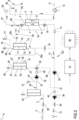
- FIG. 1 An apparatus 1 for extracorporeal treatment of blood - which may implement innovative aspects of the invention - is shown in figures 1 and 2 .
- the apparatus 1 of figure 1 is a dialysis apparatus
- the apparatus 1 of figure 2 is a hemodiafiltration apparatus.
- the apparatus 1 of figures 1 and 2 includes hydraulic circuit 100 comprising a supply line 2 having an inlet end 3 connectable to a source of treatment liquid.
- the source of treatment liquid is not shown and may for example be tap water or water coming from a centralized water preparation system.
- the supply line extends from the inlet end 3 to an outlet end 4 connectable to an inlet port of a blood treatment device 5.
- the blood treatment device 5 comprises a dialyzer
- the blood treatment device 5 comprises a hemofilter or a hemodiafilter. Note that the specific nature of the blood treatment device is not relevant to the present invention.
- the blood treatment device 5 of figures 1 and 2 has a blood chamber 6 and a liquid chamber 7 separated by a semi-permeable membrane 8: the outlet end 4 of the supply line 2 is connected to an inlet of the liquid chamber 7 of the blood treatment device 5.
- the blood chamber 6 is connected to an extracorporeal blood circuit 9 comprising a blood withdrawal line 11 having an end connected with an inlet to the blood chamber 6 and a blood return line 10 having an end connected to an outlet of the blood chamber 6.
- a blood pump 12 may operate on the extracorporeal blood circuit 9 to pump blood from a patient into the blood withdrawal line, through the blood chamber, into the blood return line and back to the patient.
- the hydraulic circuit 100 of the apparatus 1 of figures 1 and 2 further comprises a waste line 13 having an inlet end 14 connected to an outlet port the liquid chamber 7 of the blood treatment device 7 and an outlet end 15 connected to a discharge of used treatment liquid.
- the supply line 2 and the waste line 13 are configurable according to a normal configuration, where the outlet end 4 of the supply line 2 is connected to the liquid chamber 7 and in fluid communication with the inlet end 14 of the waste line 13.
- the supply line 2 and the waste line 13 are also configurable according to a by-pass configuration, where the supply line is in fluid communication with the waste line via a bypass line 16 (see dashed line 16 in figures 1 and 2 ) bypassing the blood treatment device 5 and connecting the outlet end of the supply line with the inlet end of the waste line.
- the switch from the normal to the bypass configuration may for example be obtained thanks to appropriate valves 17 and 18 or other valves which may be present in the circuit 100.
- the apparatus 1 comprises an ultrafilter 19 inserted in the supply line 2 and having a respective semipermeable membrane 20 dividing the ultrafilter into a first chamber 21 and a second chamber 22; the ultrafilter 19 is used for a plurality of treatments and is periodically changed: the ultrafilter 19 may be subject to the integrity test described below to make sure about integrity of the filter membrane before the start of each new treatment; the ultrafilter 19 also presents a first port 23 connecting a first tract 24 of the supply line 2 to the first chamber 21: basically the first tract 24 extends from inlet end 3 to the first port 23 of the ultrafilter 19; the ultrafilter 19 also presents a second port 25 connecting the second chamber 22 to a second tract 26 of the supply line extending from the second port 25 to the outlet end 4 of the supply line.
- the ultrafilter 19 may also present a third port 27 connecting the first chamber 21 to a flushing line 28 connectable to the waste line 13: in the examples of figures 1 and 2 , the flushing line 28 has at least a valve 29 for selectively opening and closing the flushing line and thus selectively forming or stopping a fluid communication between the first chamber 21 and the waste line 13.
- the apparatus 1 also includes an air inlet line 30: the air inlet line of the example of figures 1 and 2 is connected to the first tract 24 of the supply line 2 at air injection point 33 and presents an air inlet valve 31, which may be selectively opened or closed to respectively allow or prevent admission of air into the supply line 2 and towards the ultrafilter 19; note that instead or in addition to the air valve 31 an occlusive air pump may be used in order to selectively control admission of air into the air inlet line 30.
- the air inlet line 30 may be directly connected to the first chamber 21 of the ultrafilter 19.
- the apparatus 1 further comprises a fresh fluid pump 32 on the supply line 2 and a waste pump 34 on the waste line 13.
- the fresh fluid pump 32 is positioned on the first tract 24 of the supply line 2, downstream to air injection point 33 and upstream the ultrafilter 19.
- a three-way valve 35 may be positioned at the end of a further by-pass line 36 connecting the waste line 13 and the supply line 2: specifically, the three way valve 35 is positioned between the fresh fluid pump 32 and the ultrafilter 19, while the further by-pass line 36 extends between the three-way valve 35 and a junction point 37 in the-waste line 13, positioned between the waste pump 34 and the outlet end 15 of the waste line.
- the apparatus 1 may comprise an auxiliary waste pump 38 operative on the waste line 13 and positioned between the waste pump 34 and the outlet end 15 of the waste line.
- a general water inlet valve 39 operable to selectively open and close admission of fresh liquid (fresh water) into the supply line 2 may be present at the inlet end 3 of the supply line 2
- a general waste outlet valve 40 operable to selectively open and close discharge of waste liquid out of the waste line 13 may be present at the outlet end of waste line 13.
- the apparatus 1 of figures 1 and 2 furthermore comprises one or more pressure sensors as described below.
- at least one pressure sensor 41 is configured for directly or indirectly detecting pressure in the second chamber of the ultrafilter.
- the pressure sensor 41 may be directly connected to the second chamber 22 of the ultrafilter 19 or it may be positioned on the second tract 26 of the supply line or on the waste line in correspondence of the tract of waste line extending between the inlet end 14 and the waste pump 34.
- the apparatus may include an auxiliary waste pump 38 and, in this case, an auxiliary pressure sensor 42 is positioned on the waste line between the waste pump 34 and the auxiliary waste pump 38.
- the apparatus may include an optional water inlet ultrafilter 43, which is operative on the supply line immediately downstream the water inlet valve 39: also the water inlet ultrafilter 43 may be periodically changed and, in the example herein described, is not subject to any integrity test procedure.
- the apparatus of figures 1 and 2 includes a controller 50.
- the controller 50 is connected to the valves, pumps and pressure sensors described above and configured to control operation of the apparatus 1.
- the controller 50 is connected to the air valve 31, the waste pump 34, (if present) the waste pump 38, the pressure sensor 41 and (if present) the auxiliary pressure sensor 42.
- the controller 50 may be connected to a user interface 51 and be configured to receive inputs from an operator and then perform execution of an extracorporeal blood treatment based on the operator's input: the present disclosure does not provide further details on the controller role in the handling of the blood treatment as this is not relevant to the present invention.
- a safety pressure sensor 90 is located between fresh fluid pump 32 and three-way valve 35.
- the controller may be configured to stop operation of fresh fluid pump 32 once the pressure difference between pressure detected by sensor 41 and pressure detected by safety pressure sensor 90 exceeds an identified safety threshold to prevent from pressurize air in chamber 21.
- pressure ratio between pressure detected by sensor 41 and pressure detected by safety pressure sensor 90 may be used in place of pressure difference.
- the controller 50 is configured to automatically (or upon operator's request) execute an ultrafilter integrity test procedure as herein described in further detail. Note that before initiating the ultrafilter integrity test procedure, the controller 50 may also be configured or programmed to execute a number of per se known phases such as coordinating the filling and flushing of the hydraulic circuit and operate valves 17 and 18 to put the hydraulic circuit and in particular the supply line and the waste line in a by-pass configuration (see dash lines in figures 1 and 2 by-passing the blood treatment device 5).
- the controller 50 is configured or programmed to execute an integrity test procedure for checking whether the membrane 20 of the ultrafilter 19 is intact or not.
- the integrity test procedure comprises the following steps.
- the controller 50 causes filling with air of the first chamber 21 of the ultrafilter 19 (step 110 in figure 3 ): this is achieved by opening the air valve 31 (or possibly operating the air pump 31) and creating a suction of air towards said first chamber of the ultrafilter.
- the fresh fluid pump 32 and the waste pump 34 are is also operated, for example when opening the air valve or even before opening the air valve 31 (or in case an air pump 31 is used when operating or before operating the air pump 31).
- the fresh fluid pump 32 may be operated at a given angular speed while the waste pump 34 may be operated in closed loop based on a first set pressure P1 which is a desired value to be sensed at the pressure sensor 41.
- the waste pump 34 may be operated in closed loop with the first set pressure P1 at pressure sensor 41 set equal to - 350 mmHg as control loop parameter (i.e. 350mmHg below the atmospheric pressure present in the ambient where the apparatus is installed).
- both waste pump 34 and auxiliary waste pump 38 may (during this phase) be operated in closed loop based on the first set desired pressure P1 to be sensed at the pressure sensor 41 for pump 34 and to be sensed at auxiliary pressure sensor 42 for pump 38.
- the first set pressure value P1 (e.g., - 350 mmHg) is in this case the same for both pumps.
- the controller 50 is configured to form a negative pressure or further increase the value of negative pressure in the second chamber of the ultrafilter (step 111 in figure 3 - as always negative pressure is intended relative to the atmospheric pressure present in the ambient where the machine operates; therefore increasing the value of the negative pressure means making the pressure further below the atmospheric pressure present in the environment where the apparatus is installed) by continuing to operate the waste pump, or the waste pumps if two waste pumps are present.
- the controller 50 controls operation of the waste pump 34 in closed loop based on a second set negative pressure value P2 (e.g., - 600 mmHg), which shall be reached by pressure sensed by the pressure sensor 41 and which is more negative than the first pressure value P1 (again relative to ambient pressure present where the apparatus is installed).
- P2 e.g., - 600 mmHg
- both waste pump 34 and auxiliary waste pump 38 may (during this phase) be operated in closed loop based on second set negative pressure value P2 to be sensed at the pressure sensor 41 for pump 34 and to be sensed at auxiliary pressure sensor 42 for pump 38.
- the first set pressure value P1 may be selected in a pressure range between -150 and -450 mm Hg, while the second set pressure value P2 may be selected in the range between - 300 and - 700 mm Hg (with the condition that the second pressure value be at least 100 mm Hg more negative than the first set pressure value).
- the first set pressure value P1 may be selected in a pressure range allowing to drain the ultrafilter at moderate flow rates in order to avoid excessive stress on the membrane; the second set pressure value P2 may be selected such as to have an appreciable delta pressure with no residual flow, thus avoiding excessive stresses on the membrane and degasification that could cause exceeding the membrane bubble point (thus resulting into possible false alarms).
- the controller provides for verifying (step 112 in figure 3 ), while the waste pump 34 is running (or both the waste pump 34 and the waste pump 38 are still running), if the pressure sensed by the pressure sensor 41 reaches a set negative pressure threshold Pt, for then determining (step 113) that the ultrafilter semipermeable membrane has a multi-fiber break if the pressure sensed by the pressure sensor 41 during the verification step does not reach the set negative pressure threshold Pt within a set time interval T.
- This verification step may include checking pressure at the pressure sensor 41 after expiration of time interval T; alternatively one may envisage to measure the time interval at which the negative pressure threshold Pt is reached.
- the set negative pressure threshold has a negative value intermediate between said first set pressure value and said second set pressure value. For example if the first pressure value is set at -350 mm Hg and the second pressure value is set at - 600 mm Hg, the pressure threshold may be equal to - 500 mm Hg.
- the set pressure threshold has a negative value aimed at identifying multi-fiber breaks, thus providing an early detection.
- the time interval (i.e., the interval by which the pressure sensed by the pressure sensor 41 should reach the set negative pressure threshold to exclude a multi-fiber break of the ultrafilter membrane) is counted by the controller starting from the moment at which the controller imposes the second negative pressure as setting to control the waste pump 34 (or to both waste pumps 34 and 38). This time interval lasts 10 to 60 seconds, for example 30 seconds.
- the integrity test procedure may further comprise the following additional steps which the controller is configured to execute after steps 110 to 113 described above.
- the controller is configured to command the appropriate components for hydraulically isolating the ultrafilter: as it is known to the skilled person hydraulic isolation of the ultrafilter may take place in different ways depending upon the specific design of the hydraulic circuit 100.
- the controller may command closure of at least valves 29, 40 and 35 (or other equivalent valves blocking flow to the first chamber 21) and stop of the pumps 32, 34 and 38. Then, the controller (step 115 in fig.
- auxiliary negative pressure threshold Pt2 for example below -350 mmHg, again relative to atmospheric pressure present in the ambient where the machine is installed
- dP/dt variation by unit of time
- the auxiliary negative pressure threshold Pt2 is less negative than the pressure threshold Pt (relative to atmospheric pressure present in the ambient where the machine is installed, thus Pt2 is closer than Pt to atmospheric pressure).
- the set pressure differential ⁇ P is chosen at a value suitable to detect multi-fiber breaks; in addition and in accordance with a further aspect, the controller 50 may be configured to sample the dP/dt values giving more weight to pressure values at the beginning of the detection phase when delta pressure is at its highest values (for example using a low-pass filter).
- the controller 50 (step 121) is configured for then determining that the semipermeable membrane of the ultrafilter 19 has a multi-fiber break if the two conditions (steps 116a, 116b) are not both met.
- the integrity test procedure may also comprise the following further steps (steps 117-120 in figure 3 ) which the controller is configured to execute in order to determine if the membrane 20 of the ultrafilter 21 has a single fiber break.
- the further steps 117-120 described below are, in one aspect of the invention, executed after having verified that membrane 20 of the same ultrafilter 21 has no multi-fiber breaks (steps 110-113 and steps 114-116).
- the check for a possible single fiber break may be made as last check, thereby avoiding to carry out unnecessary steps if it is concluded that there is a higher ranking problem, namely a multi-fiber break.
- the integrity test procedure may therefore be configured to hydraulically isolate the (or maintain hydraulic isolation of) ultrafilter 19 and then receiving pressure values detected by the pressure sensor 41 during a further test interval after said transitory period following hydraulic isolation of the ultrafilter.
- steps 114-115 are executed after hydraulic isolation of the ultrafilter but during pressure stabilization, the following steps are executed after having waited a relatively long time interval (longer than said transitory period) after which it is expected that, absent fiber integrity problems, pressure should be highly stable.
- the controller 50 is configured, after waiting for expiration of the transitory period and during the further test interval, for verifying if a variation by unit of time (dP/dt) of said pressure values detected by the pressure sensor 41 during the further test interval remains below a further set pressure differential ⁇ p2 during at least a portion lasting n seconds of the further test interval (step 117).
- the further set pressure differential ⁇ p2 may be in the range between 1 and 3 mmHg and in a specific example it may be equal to 2 mmHg. More in general, the further set pressure differential ⁇ p2 is set in order to detect a single broken fiber ( ⁇ p2 may in practice be a fraction, e.g., 50% compared to said set pressure differential ⁇ P).
- the test interval is relatively short and may last 5 to 30 seconds, for instance 10 seconds; therefore, the controller checks if dp/dt stays below for example 2 mmHg during a portion of e.g., 4 seconds of the test interval (step 117) and also checks expiration of the test interval (118); the controller is configured to then establish that the membrane of the ultrafilter has a single-fiber break (step 119) if the check of step 117 is not positively passed before expiration of the test interval (step 118), i.e., before expiration of the 10 seconds in this example. Otherwise, if before expiration of the test interval, dp/dt stays below ⁇ p2 (in this example below 2 mmHg) for n seconds (in this example for consecutive 4 seconds), then it is determined that the ultrafilter membrane is intact (step 120).
- the apparatus of figure 2 has, in addition to the ultrafilter 20, an auxiliary ultrafilter 70 inserted in the second tract 26 of the supply line 2.
- the auxiliary ultrafilter 70 is used for a plurality of treatments and is periodically changed: for this reason also ultrafilter 70 may be subject to the integrity test described below to make sure about integrity of the filter membrane before the start of each new treatment.
- the auxiliary ultrafilter 70 has a semipermeable membrane 71 dividing the auxiliary ultrafilter into a respective first chamber 72 and a respective second chamber 73: the auxiliary ultrafilter may be structurally identical to the ultrafilter 20.
- the auxiliary ultrafilter 70 presents a first port 74 connecting, via first portion 26a of second tract 26, the first chamber 72 to second port 25 of the ultrafilter 19 second chamber 22.
- the auxiliary ultrafilter 70 also includes a respective second port 75 connecting the second chamber 73 of the auxiliary ultrafilter 70 to a second portion 26b of the second tract 26 of the supply line 2.
- an infusion line 81 may depart from the second portion 26b of the second tract 26 of line 2: in particular in the example of figure 2 , infusion line 81 departs from bifurcation point 80 and may lead to an infusion port 83, which may be present on an accessible portion of the apparatus 1 (for example on the apparatus front panel), to which one or more replacement fluid lines 84 and 85 may be connected.
- An auxiliary air inlet line 76 is connected to the first chamber 72 of the auxiliary ultrafilter 70 or to the first portion 26a of the second tract of the supply line: the air inlet line 76 is provided with a respective auxiliary air valve 77 (or with an auxiliary occlusive air pump) in order to selectively open and close admission of air via the air inlet line 76 under the control of controller 50 and allow air filling of the first chamber of the auxiliary ultrafilter during execution of the integrity test procedure of the semipermeable membrane 71.
- pressure sensor 41 may be configured for detecting pressure in one of the second chamber of the ultrafilter, the second portion of the second tract of the supply line, or the waste line (this last alternative is shown in figure 2 ).
- An auxiliary flush line 86 connects a third port 87 of the first chamber of the auxiliary ultrafilter 70 to the waste line, and an auxiliary flush valve 88 is positioned on the flush line 86 to selectively open and close the first chamber of the auxiliary ultrafilter 70 to the waste line.
- the controller 50 is configured to carry out, with the supply line and the waste line in by-pass configuration, an auxiliary integrity test procedure on the auxiliary ultrafilter 70.
- the auxiliary test procedure on the ultrafilter is also represented in figure 4 : in any case most steps of the auxiliary test procedure are similar to those of the test procedure conducted on the ultrafilter 20.
- the controller 50 initially causes filling with air of the first chamber 72 of the ultrafilter 70 (step 110 in figure 4 ): this is achieved by opening the air valve 77 (or activating an air pump on the auxiliary air inlet line) and creating a suction of air towards said first chamber of the ultrafilter.
- the waste pump 34 or the waste pumps 34 and 38 is/are operated, for example when opening the air valve or even before opening the air valve 77 (in case an occlusive air pump is used in place of the air valve the pump 34 or the pumps 34 and 38 may be operated in synchronism with the occlusive air pump or even before starting operation of the occlusive air pump).
- the waste pump 34 may be operated in closed loop based on a first set pressure P1' which is a desired value to be sensed at the pressure sensor 41.
- the waste pump 34 may be operated in closed loop with the first set pressure P1' at pressure sensor 41 set equal to - 300 mmHg as control loop parameter.
- both waste pump 34 and auxiliary waste pump 38 may (during this phase) be operated in closed loop based on the first set desired pressure P1' to be sensed at the pressure sensor 41 for pump 34 and to be sensed at auxiliary pressure sensor 42 for pump 38.
- the first set pressure value P1' (e.g., - 300 mmHg) may be the same for both pumps.
- pressure sensor 41 In case pressure sensor 41 immediately reaches the P1' first set pressure value, thus causing the waste pump 34 (and if present also pump 38) to decelerate or stop without removing the water supposed to be still present in chamber 72, this identifies that the chamber 72 is in reality already empty.
- the controller 50 may also be configured, in accordance with an ancillary aspect, to check a time related parameter (step 130) such as the time necessary to reach the first pressure value P1' or the pump rotation frequency of waste pump 34 (and/or 38), or the pump rotation period of pump 34 (and/or 38), and compare this detected time related parameter with a corresponding reference threshold, assigning the identification of a multi-fiber break problem in membrane 20 of ultrafilter 19 if the check on the time related parameter is not passed (step 131).
- a time related parameter such as the time necessary to reach the first pressure value P1' or the pump rotation frequency of waste pump 34 (and/or 38), or the pump rotation period of pump 34 (and/or 38
- the controller 50 is configured to form a negative pressure or increase the negative pressure in the second chamber 73 of the ultrafilter (step 111 in figure 4 - negative pressure is intended relative to the atmospheric pressure present in the ambient where the machine operates; therefore increasing the value of the negative pressure means making the pressure further below the atmospheric pressure present in the environment where the apparatus is installed) by continuing to operate the waste pump or the waste pumps if two waste pumps are present.
- the controller 50 controls operation of the waste pump 34 in closed loop based on a second set negative pressure value P2' (e.g., - 600 mmHg), which shall be reached by pressure sensed by the pressure sensor 41 and which is more negative than the first pressure value P1'.
- a second set negative pressure value P2' e.g., - 600 mmHg
- both waste pump 34 and auxiliary waste pump 38 may (during this phase) be operated in closed loop based on second set negative pressure value P2' to be sensed at the pressure sensor 41 for pump 34 and to be sensed at auxiliary pressure sensor 42 for pump 38.
- the first set pressure value P1' may be selected in a pressure range between -150 and -450 mm Hg, while the second set pressure value P2' may be selected in the range between - 300 and - 700 mm Hg (with the condition that the second pressure value be at least 100 mm Hg more negative than the first set pressure value).
- the first set pressure value P1' may be selected in a pressure range allowing to drain the ultrafilter at moderate flow rate in order to avoid excessive stress on the membrane; the second set pressure value P2' may be selected to form a sufficient delta pressure with no residual flow, also avoiding excessive stress on the membrane and degasification that could cause exceeding the membrane bubble point exceeding.
- the controller may be configured to put first port 74 in communication with line 15, for example by opening an ancillary by-pass valve 91 placed on a line connecting the first tract 26a with the waste line 15.
- the controller opens the ancillary by-pass valve 91 for a short time frame (e.g., 1 to 5 seconds) to ensure the complete draining of the ultrafilter 70 from top to bottom.
- the controller provides for verifying (step 112 in figure 3 ), while the waste pump 34 is running (or both the waste pump 34 and the waste pump 38 are still running), if the pressure sensed by the pressure sensor 41 reaches a set negative pressure threshold Pt', for then determining (step 113) that the ultrafilter membrane 71 has a multi-fiber break if the pressure sensed by the pressure sensor 41 during the verification step does not reach the set negative pressure threshold Pt' within a set time interval T'.
- This verification step may include checking pressure at the pressure sensor 41 after expiration of time interval T'; alternatively, one may envisage to measure the time interval at which the negative pressure threshold Pt' is reached.
- the set negative pressure threshold Pt' has a negative value intermediate between said first set pressure value P1' and said second set pressure value P2'.
- the pressure threshold Pt' may be equal to - 450 mm Hg.
- the pressure threshold Pt' may be selected to have a value which is a negative value intermediate between said first set pressure value P1' and said second set pressure value P2' and which aims at early identification of multi-fiber breaks.
- the set time interval T' (i.e., the interval by which the pressure sensed by the pressure sensor 41 should reach the set negative pressure threshold Pt' to exclude a multi-fiber break of the ultrafilter membrane) is counted by the controller starting from the moment at which the controller imposes the second negative pressure P2' as setting to control the waste pump 34 (or to both waste pumps 34 and 38).
- This time interval T' may last 10 to 60 seconds, for example of 30 seconds.
- the auxiliary integrity test procedure may further comprise the following additional steps which the controller 50 is configured to execute after steps 110 to 113 described above.
- the controller 50 is configured to command the appropriate components to hydraulically isolating the ultrafilter 70: for example, with reference to figure 2 , the controller may command closure of valves 35, 40 and 88 (and possibly also valve 77) and stop of the pumps 32, 34 and 38. Then, the controller (step 115 in fig.
- the controller 50 is configured for verifying (step 116) if two stability conditions (116a, 116b) are met, namely that the pressure values detected by pressure sensor 41 at the end of the transitory period be below an auxiliary negative pressure threshold Pt2' (for example below -350 mmHg), and that the variation by unit of time (dP/dt) of the pressure values detected by pressure sensor 41 at the end of the transitory period be sufficiently small and specifically be below a set pressure differential ⁇ P', for example below 4 mmHg/s.
- Pt2' for example below -350 mmHg
- the controller 50 may be configured to sample the dP/dt values giving more weight to pressure values at the beginning of the detection phase when delta pressure is at its highest values (for example using a low-pass filter).
- the controller 50 (step 121) is configured for then determining that the membrane of the ultrafilter 19 has a multi-fiber break if the two conditions (steps 116a, 116b) are not both met.
- the auxiliary integrity test procedure on ultrafilter 70 may also comprise the following further steps which the controller is configured to execute in order to determine if the membrane 71 has a single fiber break.
- the further steps described below are, in one aspect of the invention, executed after having verified that membrane 70 of the same ultrafilter 71 has no multi-fiber breaks (steps 110-113 and steps 114-116).
- the check for a possible single fiber break may be made as last check on the ultrafilter 70, thereby avoiding to carry out unnecessary steps if it is concluded that there is a higher ranking problem, namely a multi-fiber break.
- the integrity test procedure may therefore be configured to hydraulically isolate (or maintain hydraulic isolation of) the auxiliary ultrafilter 70 and then receiving pressure values detected by the pressure sensor 41 during a further test interval after the transitory period following hydraulic isolation of the ultrafilter 70.
- steps 114-115 are executed after hydraulic isolation of the ultrafilter 70 but during pressure stabilization, the following steps are executed after having waited a relatively long transitory period after which it is expected that - absent fiber integrity problems - pressure should be highly stable.
- the controller 50 is configured, after waiting for expiration of the transitory period, for verifying if a variation by unit of time (dP/dt) of said pressure values detected by the pressure sensor 41 during the further test interval remains below a further set pressure differential ⁇ p2' during at least a portion lasting n seconds of the further test interval (step 117).
- the further set pressure differential ⁇ p2' may be in the range between 1 and 3 mmHg and in a specific example it may be equal to 2 mmHg. More in general, the further set pressure differential ⁇ p2' is set in order to detect a single broken fiber ( ⁇ p2' may in practice be a fraction, e.g., 50% compared to said set pressure differential ⁇ P').
- the test interval is relatively short and may last 5 to 30 seconds, for instance 10 seconds; therefore, the controller checks if dp/dt stays below for example 2 mmHg during a portion of e.g., 4 seconds of the test interval (step 117) and also checks expiration of the test interval (118); the controller is configured to then establish that the membrane of the auxiliary ultrafilter 70 has a single-fiber break (step 119) if the check of step 117 is not positively passed before expiration of the test interval (step 118), i.e., before expiration of the 10 seconds in this example.
- dp/dt stays below ⁇ p2' (in this example below 2 mmHg) for n seconds (in this example for consecutive 4 seconds), then it is determined that the auxiliary ultrafilter membrane is intact (step 120).
- the apparatus makes use of at least one controller 50.
- This controller may comprise a digital processor (CPU) with memory (or memories), an analogical type circuit, or a combination of one or more digital processing units with one or more analogical processing circuits.
- CPU digital processor
- memory or memories
- an analogical type circuit or a combination of one or more digital processing units with one or more analogical processing circuits.
- the controller is "configured” or "programmed” to execute certain steps: this may be achieved in practice by any means which allow configuring or programming the controller.
- one or more programs are stored in an appropriate memory: the program or programs containing instructions which, when executed by the controller, cause the controller to execute the steps described and/or claimed in connection with the controller.
- the circuitry of the controller is designed to include circuitry configured, in use, to process electric signals such as to execute the controller steps herein disclosed.
- the invention also concerns a method of testing the integrity of an ultrafilter membrane of an ultrafilter.
- the ultrafilter may be part of an extracorporeal blood treatment apparatus.
- the method may be used for testing the integrity of the membrane of one or all the ultrafilters described above in connection with the apparatus of figure 1 or the apparatus of figure 2 .
- the method described below may be implemented by any apparatus 1 described above or claimed in any one of the appended claims.
- the method of the invention detects if the ultrafilter membrane is subject to multi-fiber breaks or to a single fiber break.
- the method comprises executing the following steps (please refer again to figure 3 and to figure 4 ):
- the set time interval of said verifying step is a set time interval calculated from start of the step of extraction of liquid from the second chamber, or calculated from end of filling with air the first chamber of the ultrafilter under test.
- step 116 comprises the following sub-steps:
- the method determines that the membrane of the ultrafilter has a multi-fiber break. In other words, it is sufficient that one of the two conditions of sub-steps 116a, 116b not be met to conclude for the presence of a multi-fiber break.
- the method provides for a sequence of steps, namely steps 117-120) aimed at determining the possible presence in the membrane of a single fiber break.
- the method may comprise the following additional steps:
- step 119 it is determined that the membrane of the ultrafilter has a single-fiber break if the above last condition is not met. If, instead, the above last condition is met, the method provides for informing an operator or for issuing a corresponding signal to the controller of the apparatus 1 (step 120).
- the behavior of the draining pump 34 (and 38) may be monitored and used to identify a multi-broken fiber in the membrane of the first ultrafilter, causing the first chamber of the ultrafilter under testing to be empty when expected to be still full of liquid (steps 130, 131).
- the method may include to check a time related parameter (step 130) such as the time necessary to reach P1' or the pump rotation frequency, or the pump rotation period, and compare this detected time related parameter with a corresponding reference threshold, assigning the identification of a multi-fiber break problem in the membrane of ultrafilter 19 if the check on the time related parameter is not passed (step 131).
- a time related parameter such as the time necessary to reach P1' or the pump rotation frequency, or the pump rotation period
- a method of testing ultrafilters may use only steps 110, 111 and 114 to 120 (without steps 112-113) to identify whether an hydraulically isolated ultrafilter has a single fiber break or a multiple fiber break, in particular by first creating a negative pressure in the second chamber of the ultrafilter (e.g., executing steps 110 and 111 described above) and then detecting the behavior of derivative dp/dt to decide whether the ultrafilter membrane is intact or has a single fiber break or multiple fiber breaks, as described above in connection with steps 116a and 116b and with steps 117 and 118, and as indicated in aspects from 53rd to 81st of the summary section.
Landscapes
- Engineering & Computer Science (AREA)
- Health & Medical Sciences (AREA)
- Water Supply & Treatment (AREA)
- Chemical Kinetics & Catalysis (AREA)
- Chemical & Material Sciences (AREA)
- Heart & Thoracic Surgery (AREA)
- Urology & Nephrology (AREA)
- Hematology (AREA)
- Biomedical Technology (AREA)
- Life Sciences & Earth Sciences (AREA)
- Animal Behavior & Ethology (AREA)
- General Health & Medical Sciences (AREA)
- Public Health (AREA)
- Veterinary Medicine (AREA)
- Anesthesiology (AREA)
- Vascular Medicine (AREA)
- Emergency Medicine (AREA)
- External Artificial Organs (AREA)
Applications Claiming Priority (3)
| Application Number | Priority Date | Filing Date | Title |
|---|---|---|---|
| EP18169176.7A EP3560577A1 (fr) | 2018-04-25 | 2018-04-25 | Appareil et procédé pour tester l'intégrité d'une membrane d'ultrafiltration |
| EP19719262.8A EP3784370B1 (fr) | 2018-04-25 | 2019-04-19 | Appareil et procédé pour tester l'intégrité d'une membrane d'ultrafiltration |
| PCT/EP2019/060246 WO2019206837A1 (fr) | 2018-04-25 | 2019-04-19 | Appareil et procédé pour tester l'intégrité d'une membrane ultra-filtrante |
Related Parent Applications (1)
| Application Number | Title | Priority Date | Filing Date |
|---|---|---|---|
| EP19719262.8A Division EP3784370B1 (fr) | 2018-04-25 | 2019-04-19 | Appareil et procédé pour tester l'intégrité d'une membrane d'ultrafiltration |
Publications (1)
| Publication Number | Publication Date |
|---|---|
| EP4353276A2 true EP4353276A2 (fr) | 2024-04-17 |
Family
ID=62063379
Family Applications (3)
| Application Number | Title | Priority Date | Filing Date |
|---|---|---|---|
| EP18169176.7A Withdrawn EP3560577A1 (fr) | 2018-04-25 | 2018-04-25 | Appareil et procédé pour tester l'intégrité d'une membrane d'ultrafiltration |
| EP24159393.8A Pending EP4353276A2 (fr) | 2018-04-25 | 2019-04-19 | Appareil et procédé pour tester l'intégrité d'une membrane ultra-filtrante. |
| EP19719262.8A Active EP3784370B1 (fr) | 2018-04-25 | 2019-04-19 | Appareil et procédé pour tester l'intégrité d'une membrane d'ultrafiltration |
Family Applications Before (1)
| Application Number | Title | Priority Date | Filing Date |
|---|---|---|---|
| EP18169176.7A Withdrawn EP3560577A1 (fr) | 2018-04-25 | 2018-04-25 | Appareil et procédé pour tester l'intégrité d'une membrane d'ultrafiltration |
Family Applications After (1)
| Application Number | Title | Priority Date | Filing Date |
|---|---|---|---|
| EP19719262.8A Active EP3784370B1 (fr) | 2018-04-25 | 2019-04-19 | Appareil et procédé pour tester l'intégrité d'une membrane d'ultrafiltration |
Country Status (4)
| Country | Link |
|---|---|
| US (2) | US11571501B2 (fr) |
| EP (3) | EP3560577A1 (fr) |
| CN (1) | CN112020391B (fr) |
| WO (1) | WO2019206837A1 (fr) |
Families Citing this family (1)
| Publication number | Priority date | Publication date | Assignee | Title |
|---|---|---|---|---|
| CN114713037B (zh) * | 2022-06-10 | 2022-09-20 | 北京先通国际医药科技股份有限公司 | 在线滤膜完整性测试装置及方法、及其用途 |
Citations (3)
| Publication number | Priority date | Publication date | Assignee | Title |
|---|---|---|---|---|
| EP1898973B1 (fr) | 2005-07-01 | 2010-05-26 | Gambro Lundia AB | Appareil pour tester un filtre |
| WO2012124425A1 (fr) | 2011-03-15 | 2012-09-20 | 澁谷工業株式会社 | Dispositif d'hémodialyse |
| EP1897605B1 (fr) | 2006-09-05 | 2014-04-09 | Bellco S.r.l. | Procédé et dispositif pour tester l'intégrité de filtres de circuit de dialyse |
Family Cites Families (40)
| Publication number | Priority date | Publication date | Assignee | Title |
|---|---|---|---|---|
| GB2132366B (en) | 1982-12-27 | 1987-04-08 | Brunswick Corp | Method and device for testing the permeability of membrane filters |
| EP0139202B1 (fr) | 1983-09-09 | 1989-04-12 | Fujisawa Pharmaceutical Co., Ltd. | Appareil pour tester des membranes filtrantes, et appareil de stérilisation de liquides à l'aide d'une membrane filtrante |
| DE3444671A1 (de) | 1984-12-07 | 1986-06-12 | Fresenius AG, 6380 Bad Homburg | Haemodiafiltrationsgeraet |
| DE3641843A1 (de) | 1986-12-08 | 1988-06-16 | Fresenius Ag | Haemodialysevorrichtung mit sterilisiereinrichtung |
| DE3923078C1 (fr) | 1989-07-13 | 1990-09-27 | Fresenius Ag, 6380 Bad Homburg, De | |
| ES2070990T3 (es) | 1990-12-23 | 1995-06-16 | Fresenius Ag | Instalacion automatica para la elaboracion de concentrado mediante la mezcla de liquido con solido soluble. |
| DE4209519C3 (de) | 1992-03-24 | 2000-06-15 | Pall Corp | Verfahren und Gerät zum schnellen Testen der Unversehrtheit von Filterelementen |
| US5282380A (en) * | 1992-06-30 | 1994-02-01 | Millipore Corporation | Integrity test for membranes |
| DE4239937C2 (de) * | 1992-11-27 | 1995-08-24 | Fresenius Ag | Verfahren zur Feststellung der Funktionsfähigkeit einer Teileinrichtung eines Hämodialysegerätes und Vorrichtung zur Durchführung dieses Verfahrens |
| US5591344A (en) | 1995-02-13 | 1997-01-07 | Aksys, Ltd. | Hot water disinfection of dialysis machines, including the extracorporeal circuit thereof |
| DE19534417A1 (de) * | 1995-09-16 | 1997-03-20 | Fresenius Ag | Verfahren zum Überprüfen von mindestens einem im Dialysierflüssigkeitssystem einer Vorrichtung zur extrakorporalen Blutbehandlung angeordneten Filter |
| FR2749190B1 (fr) | 1996-05-28 | 1998-09-18 | Omnium Traitement Valorisa | Procede et installation pour tester in situ l'integrite des membranes de filtration |
| DE19700466A1 (de) | 1997-01-09 | 1998-07-16 | Polaschegg Hans Dietrich Dr | Einrichtung und Verfahren zur Hämodiafiltration |
| DE19757523C1 (de) | 1997-12-23 | 1999-04-22 | Fresenius Medical Care De Gmbh | Verfahren zur Überwachung der Funktionsfähigkeit einer Teileinrichtung einer Blutbehandlungsvorrichtung und Blutbehandlungsvorrichtung mit einer Einrichtung zu einer solchen Überwachung |
| IT1299946B1 (it) | 1998-04-01 | 2000-04-04 | Bellco Spa | Macchina per emodialisi. |
| DE19832451C1 (de) | 1998-07-18 | 1999-08-26 | Fresenius Medical Care De Gmbh | Verfahren und Vorrichtung zum Überprüfen des ordnungsgemäßen Austauschs eines gebrauchten Filters in einer Vorrichtung zur extrakorporalen Blutbehandlung |
| CA2338952C (fr) | 1998-07-31 | 2007-04-03 | Nephros, Inc. | Procede efficace d'hemodiafiltration |
| US6324898B1 (en) | 1999-12-21 | 2001-12-04 | Zenon Environmental Inc. | Method and apparatus for testing the integrity of filtering membranes |
| US6649063B2 (en) | 2001-07-12 | 2003-11-18 | Nxstage Medical, Inc. | Method for performing renal replacement therapy including producing sterile replacement fluid in a renal replacement therapy unit |
| US6766259B2 (en) | 2002-07-29 | 2004-07-20 | Baxter International Inc. | System and a method for detecting fiber damage in a dialyzer |
| US7115206B2 (en) | 2002-10-15 | 2006-10-03 | Gambro Lundia Ab | Method for in-line preparation of liquid for an extracorporeal blood treatment apparatus |
| EP1592494B1 (fr) | 2003-01-07 | 2009-06-24 | NxStage Medical, Inc. | Systeme de filtration discontinue destine a la preparation d'un liquide de remplacement sterile pour la therapie renale |
| DE10328435B3 (de) | 2003-06-25 | 2005-03-24 | Fresenius Medical Care Deutschland Gmbh | Vorrichtung zur extrakorporalen Blutbehandlung mit einer Einrichtung zur Überprüfung eines Sterilfilters und Verfahren zum Überprüfen eines Sterilfilters einer extrakorporalen Blutbehandlungsvorrichtung |
| MX351817B (es) | 2003-10-28 | 2017-10-30 | Baxter Healthcare Sa | Metodos mejorados de cebado, integridad y altura sobre la cabeza y aparatos para sistemas de fluidos medicinales. |
| CA2484096A1 (fr) | 2004-10-07 | 2006-04-07 | Zenon Environmental Inc. | Methode pour localiser et reparer des fibres creuses endommagees dans des assemblages de modules a membrane avec couvercle |
| FR2894843B1 (fr) | 2005-12-20 | 2008-02-22 | Degremont Sa | Procede et dispositif de test d'integrite de membranes de filtration |
| DE102006050272B4 (de) | 2006-10-23 | 2008-07-24 | Fresenius Medical Care Deutschland Gmbh | Hämodialysegerät, Hämodiafiltrationsgerät, Verfahren zur Probennahme bei solchen Geräten und Probenentnahmeset zur Anwendung bei solchen Geräten und Verfahren |
| US20080202210A1 (en) | 2007-02-28 | 2008-08-28 | Varian, Inc. | Test gas leak detection using a composite membrane |
| DE102007037099A1 (de) | 2007-08-07 | 2009-02-19 | Fresenius Medical Care Deutschland Gmbh | Verfahren und Vorrichtung zum Konstanthalten eines pH-Wertes einer medizinischen Flüssigkeit beim Ablassen aus einem Behälter |
| MX2011002251A (es) * | 2008-08-27 | 2011-05-19 | Deka Products Lp | Arquitectura de control y metodos para sistemas de tratamiento de la sangre. |
| DE102009048920A1 (de) | 2009-10-10 | 2011-04-14 | Fresenius Medical Care Deutschland Gmbh | Vorrichtung und Verfahren zur Überprüfung eines Filters für eine extrakorporale Blutbehandlungsvorrichtung |
| JP2013513470A (ja) | 2009-12-10 | 2013-04-22 | ネフロス,インク. | 液体浄化システムにおいてフィルター完全性を検査するための手段 |
| JP5548001B2 (ja) | 2010-03-25 | 2014-07-16 | 日機装株式会社 | 血液浄化装置 |
| EP2418012A1 (fr) | 2010-08-11 | 2012-02-15 | Gambro Lundia AB | Dispositif et procédé pour tester des filtres |
| DE102011008223B4 (de) | 2011-01-10 | 2019-07-04 | Fresenius Medical Care Deutschland Gmbh | Dialysebehandlungseinheit |
| DE102011082284A1 (de) | 2011-09-07 | 2013-03-07 | Krones Aktiengesellschaft | Hygienischer Integritätstest bei Ultrafiltrationsanlagen |
| EP2567750B1 (fr) | 2011-09-08 | 2014-12-24 | Gambro Lundia AB | Membrane en fibre creuse |
| EP3037156A1 (fr) | 2014-12-22 | 2016-06-29 | Gambro Lundia AB | Séchage de membranes creuses en ligne |
| CA2986201A1 (fr) | 2015-06-05 | 2016-12-08 | Debiotech S.A. | Test d'un traitement medical d'un fluide |
| DE102015120003A1 (de) | 2015-11-18 | 2017-06-01 | B. Braun Avitum Ag | Verfahren zur Sterilisation und Integritätsprüfung von Dialysatoren |
-
2018
- 2018-04-25 EP EP18169176.7A patent/EP3560577A1/fr not_active Withdrawn
-
2019
- 2019-04-19 US US17/050,050 patent/US11571501B2/en active Active
- 2019-04-19 WO PCT/EP2019/060246 patent/WO2019206837A1/fr unknown
- 2019-04-19 EP EP24159393.8A patent/EP4353276A2/fr active Pending
- 2019-04-19 EP EP19719262.8A patent/EP3784370B1/fr active Active
- 2019-04-19 CN CN201980028485.6A patent/CN112020391B/zh active Active
-
2023
- 2023-02-06 US US18/105,977 patent/US20230181806A1/en active Pending
Patent Citations (3)
| Publication number | Priority date | Publication date | Assignee | Title |
|---|---|---|---|---|
| EP1898973B1 (fr) | 2005-07-01 | 2010-05-26 | Gambro Lundia AB | Appareil pour tester un filtre |
| EP1897605B1 (fr) | 2006-09-05 | 2014-04-09 | Bellco S.r.l. | Procédé et dispositif pour tester l'intégrité de filtres de circuit de dialyse |
| WO2012124425A1 (fr) | 2011-03-15 | 2012-09-20 | 澁谷工業株式会社 | Dispositif d'hémodialyse |
Also Published As
| Publication number | Publication date |
|---|---|
| EP3560577A1 (fr) | 2019-10-30 |
| CN112020391A (zh) | 2020-12-01 |
| US20230181806A1 (en) | 2023-06-15 |
| US20210093771A1 (en) | 2021-04-01 |
| EP3784370B1 (fr) | 2024-02-28 |
| EP3784370A1 (fr) | 2021-03-03 |
| US11571501B2 (en) | 2023-02-07 |
| WO2019206837A1 (fr) | 2019-10-31 |
| CN112020391B (zh) | 2022-11-18 |
Similar Documents
| Publication | Publication Date | Title |
|---|---|---|
| JP5185835B2 (ja) | 体外血液循環路を少なくとも部分的に空にするための方法及びその方法を用いるための血液透析機械 | |
| EP2192937B1 (fr) | Appareil de perfusion | |
| US9162020B2 (en) | Method and apparatus for controlling an extra-corporeal blood treatment in a medical device | |
| JPH0518589B2 (fr) | ||
| EP2291207A1 (fr) | Circuit de fluide médical pourvu d'un détecteur de niveau bas | |
| US20230181806A1 (en) | Apparatus and method for testing integrity of an ultrafilter membrane | |
| US9514322B2 (en) | Blood treatment system, machine, and method with user interface blocking and unblocking | |
| JPH04317658A (ja) | 体外血液回路に於けるチャンバー内の血液のレベルを設定するためのデバイス | |
| WO2017001358A1 (fr) | Circuit sanguin extracorporel pour traitements en aiguille unique | |
| WO2017001357A1 (fr) | Appareil de traitement sanguin extracorporel pour traitements à aiguille unique | |
| EP0228160B1 (fr) | Dispositif de filtrage de plasma du sang | |
| EP2415491B1 (fr) | Appareil de traitement sanguin extracorporel | |
| JP5260638B2 (ja) | 単針動作での血液処理装置および方法 | |
| CN109414541B (zh) | 用于检测血液处理装置的透析液排放管线中的血液的控制单元和血液处理装置 | |
| US20210322662A1 (en) | A Control And/Or Closed-Loop Control Device For Removing Fluid from A Blood Filter | |
| US20220105252A1 (en) | Method for filling a membrane | |
| AU2022260476A1 (en) | Method for controlling a blood treatment device, and devices | |
| US20240050634A1 (en) | Bypass Line, Medical Treatment Apparatus, and Method | |
| JPH0117703B2 (fr) | ||
| JPH0221872A (ja) | 血漿分離装置およびその制御方法 |
Legal Events
| Date | Code | Title | Description |
|---|---|---|---|
| PUAI | Public reference made under article 153(3) epc to a published international application that has entered the european phase |
Free format text: ORIGINAL CODE: 0009012 |
|
| STAA | Information on the status of an ep patent application or granted ep patent |
Free format text: STATUS: THE APPLICATION HAS BEEN PUBLISHED |
|
| AC | Divisional application: reference to earlier application |
Ref document number: 3784370 Country of ref document: EP Kind code of ref document: P |
|
| AK | Designated contracting states |
Kind code of ref document: A2 Designated state(s): AL AT BE BG CH CY CZ DE DK EE ES FI FR GB GR HR HU IE IS IT LI LT LU LV MC MK MT NL NO PL PT RO RS SE SI SK SM TR |