EP4350377A1 - Magnetism measuring device - Google Patents
Magnetism measuring device Download PDFInfo
- Publication number
- EP4350377A1 EP4350377A1 EP22816100.6A EP22816100A EP4350377A1 EP 4350377 A1 EP4350377 A1 EP 4350377A1 EP 22816100 A EP22816100 A EP 22816100A EP 4350377 A1 EP4350377 A1 EP 4350377A1
- Authority
- EP
- European Patent Office
- Prior art keywords
- magnetic field
- detection signal
- magnetic
- excitation
- coil
- Prior art date
- Legal status (The legal status is an assumption and is not a legal conclusion. Google has not performed a legal analysis and makes no representation as to the accuracy of the status listed.)
- Pending
Links
Images


Classifications
-
- G—PHYSICS
- G01—MEASURING; TESTING
- G01R—MEASURING ELECTRIC VARIABLES; MEASURING MAGNETIC VARIABLES
- G01R33/00—Arrangements or instruments for measuring magnetic variables
- G01R33/02—Measuring direction or magnitude of magnetic fields or magnetic flux
- G01R33/06—Measuring direction or magnitude of magnetic fields or magnetic flux using galvano-magnetic devices
-
- A—HUMAN NECESSITIES
- A61—MEDICAL OR VETERINARY SCIENCE; HYGIENE
- A61B—DIAGNOSIS; SURGERY; IDENTIFICATION
- A61B5/00—Measuring for diagnostic purposes; Identification of persons
- A61B5/05—Detecting, measuring or recording for diagnosis by means of electric currents or magnetic fields; Measuring using microwaves or radio waves
- A61B5/0515—Magnetic particle imaging
-
- G—PHYSICS
- G01—MEASURING; TESTING
- G01R—MEASURING ELECTRIC VARIABLES; MEASURING MAGNETIC VARIABLES
- G01R33/00—Arrangements or instruments for measuring magnetic variables
- G01R33/02—Measuring direction or magnitude of magnetic fields or magnetic flux
- G01R33/06—Measuring direction or magnitude of magnetic fields or magnetic flux using galvano-magnetic devices
- G01R33/09—Magnetoresistive devices
-
- G—PHYSICS
- G01—MEASURING; TESTING
- G01R—MEASURING ELECTRIC VARIABLES; MEASURING MAGNETIC VARIABLES
- G01R33/00—Arrangements or instruments for measuring magnetic variables
- G01R33/12—Measuring magnetic properties of articles or specimens of solids or fluids
- G01R33/1276—Measuring magnetic properties of articles or specimens of solids or fluids of magnetic particles, e.g. imaging of magnetic nanoparticles
Definitions
- the present invention relates to a magnetic field measurement device and, more particularly, to a magnetic field measurement device capable of being used for magnetic particle imaging.
- Non-Patent Document 1 a magnetic field measurement device of a type that detects a magnetization change caused due to excitation of an object to be measured.
- the magnetic particle imaging device is provided with an excitation coil that applies an excitation AC magnetic field to an object to be measured containing magnetic particles and a magnetic sensor that detects a detection AC magnetic field generated by the magnetization change of the excited magnetic particles.
- the magnetic sensor is applied not only with the detection AC magnetic field but also with the excitation AC magnetic field, and when the magnetization change of the magnetic particles is made to exhibit a nonlinear response, a detection signal component and an excitation component (noise component) included in an output signal from the magnetic sensor can be separated from each other through signal processing.
- Non-Patent Document 1 B. Gleich and J. Weizenecker, Nature, 435, 1214 (2005 ).
- a magnetic field measurement device includes: a first coil that applies an excitation AC magnetic field to an object to be measured including a magnetic material to make a magnetization change of the magnetic material exhibit linear response; a first magnetic sensor that detects a primary detection AC magnetic field caused due to the magnetization change of the magnetic material to generate a primary detection signal; a second coil that generates a secondary detection AC magnetic field based on the primary detection signal; and a second magnetic sensor that detects the secondary detection AC magnetic field to generate a secondary detection signal including a non-sine wave component.
- the primary detection signal generated by the first magnetic sensor is converted back to a magnetic field, and the obtained magnetic field is detected by the second magnetic sensor, so that it is possible to obtain the secondary detection signal including a non-sine wave component without making the magnetization change of the magnetic material exhibit nonlinear response.
- This allows high-sensitivity detection of the magnetization change of the magnetic material even though the current value of a current flowing in the first coil is small and the frequency thereof is low.
- the magnetic field measurement device may further include a third coil that cancels the excitation AC magnetic field applied to the first magnetic sensor. This makes it possible to reduce a noise component included in the primary detection signal.
- the magnetic field measurement device may further include a signal processing circuit that detects a harmonic component included in the secondary detection signal. This makes it possible to remove a noise component included in the secondary detection signal.
- the current value and frequency of a current flowing in an excitation coil can be reduced.
- FIG. 1 is a schematic diagram for explaining the configuration of a magnetic field measurement device 1 according to an embodiment of the present invention.
- the magnetic field measurement device 1 is a device that detects a magnetic material P in an object to be measured positioned in a measurement area A and includes, as illustrated in FIG. 1 , magnets 11 and 12 that generate a gradient DC magnetic field ⁇ , an excitation circuit 13 connected to an excitation coil C1, and a detection coil C0 that detects a primary detection AC magnetic field caused due to a magnetization change of the magnetic material P.
- the magnetic material P may be a magnetic nanoparticle with nanosize. Using the magnetic nanoparticle as the magnetic material P allows a human body to be set as the object to be measured.
- the magnets 11 and 12 are arranged such that the S-poles or N-poles thereof face each other so as to substantially null the strength of the gradient DC magnetic field ⁇ in the measurement area A. Coils may be used in place of the magnets 11 and 12. Further alternatively, a mechanism that spatially moves the measurement area A may be provided.
- the excitation circuit 13 is a circuit for making an excitation AC current i1 flow in the excitation coil C1, whereby an excitation AC magnetic field is applied to the measurement area A.
- the excitation AC current i1 has a sine waveform. As described later, the strength of the excitation AC magnetic field is set to a value making the magnetization change of the magnetic material P positioned in the measurement area A exhibit nonlinear response.
- the nonlinear response means that the magnetic material P undergoes a magnetization change in an unsaturated region.
- the nonlinear response may include not only a case where the magnetization change is completely linear, but also a case where it includes some nonlinear component so long as the magnetization change occurs in the unsaturated region.
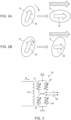
- FIG. 2 is a schematic view for explaining the magnetization change of the magnetic material P.
- the magnetization change of the magnetic material P generates a primary detection AC magnetic field.
- the primary detection AC magnetic field is detected by the detection coil C0 as a first magnetic sensor, and a primary detection signal S1 is generated.
- the above detection coil C0 is used as a magnetic sensor for detecting the primary detection AC magnetic field; however, the magnetic sensor for detecting the primary detection AC magnetic field is not limited to this, but a magnetic sensor using a magnetosensitive element may be employed.
- the excitation AC magnetic field is also applied to the magnetic material P existing outside the measurement area A, the magnetization change does not substantially occur since the direction of the magnetization M is fixed by the gradient DC magnetic field ⁇ having a predetermined strength at the outside of the measurement area A. This allows the detection coil C0 to selectively detect the magnetization change of the magnetic material P positioned within the measurement area A.
- the excitation AC magnetic field applied to the detection coil C0 is canceled by a cancel coil C3.
- a cancel current i3 is made to flow in the cancel coil C3 by a compensation circuit 14, whereby the excitation AC magnetic field applied to the detection coil C0 is canceled.
- the primary detection signal S1 is input to an amplifier circuit 15.
- the amplifier circuit 15 is an analog circuit including a differential amplifier and a filter circuit and supplies a detection AC current i2 to a magnetic field generation coil C2 based on the primary detection signal S1.
- a secondary detection AC magnetic field is generated from the magnetic field generation coil C2.
- the amplifier circuit 15 has substantially no delay since it is an analog circuit, so that a secondary detection AC magnetic field is generated in substantially real time in accordance with the primary detection AC magnetic field.
- the secondary detection AC magnetic field is detected by a second magnetic sensor 16, and a secondary detection signal S2 is generated.
- FIG. 3 is a circuit diagram of the magnetic sensor 16.
- the magnetic sensor 16 is constituted by magnetosensitive elements 21 to 24 which are full-bridge connected.
- the magnetosensitive elements 21 to 24 may be an element having high sensitivity even in a low frequency region and capable of being magnetically saturated, examples thereof including: magnetoresistive effect elements such as a TMR (Tunnel Magneto-Resistive effect) element, a GMR (Giant Magneto-Resistive effect) element, and an AMR (Anisotropic Magneto-Resistive effect) element; a hall element; and an MI (Magnetic Impedance) element.
- the magnetic sensor 16 is configured such that the secondary detection AC magnetic field generated from the magnetic field generation coil C2 is applied in mutually opposite directions to the magnetosensitive elements 21, 22 and magnetosensitive elements 23, 24. As a result, the secondary detection signal S2 corresponding to the secondary detection AC magnetic field is output from the magnetic sensor 16.
- the magnetic sensor 16 may be not only a sensor obtained by full-bridge connecting four magnetosensitive elements but also a sensor obtained by half-bridge connecting two magnetosensitive elements and a sensor using a single magnetosensitive element.
- the secondary detection signal S2 is supplied to a signal processing circuit 18 through an amplifier 17.
- the signal processing circuit 18 extracts a harmonic component included in the secondary detection signal S2 to generate a tertiary detection signal S3.
- the tertiary detection signal S3 is a final output signal of the magnetic field measurement device 1 according to the present embodiment and indicates the magnetization change of the magnetic material P positioned in the measurement area A.
- the configuration of the magnetic field measurement device 1 according to the present embodiment has been described. The following describes the operation of the magnetic field measurement device 1 according to the present embodiment.
- the excitation circuit 13 makes the excitation AC current i1 flow in the excitation coil C1 such that the magnetization change of the magnetic material P positioned in the measurement area A exhibits linear response. That is, the amount of the excitation AC current i1 supplied to the excitation coil C1 is set to a value sufficiently smaller than an amount required for making the magnetization change of the magnetic material P exhibit nonlinear response.
- FIG. 4 is a schematic graph for explaining the magnetization change of the magnetic material P, in which the vertical and horizontal axes represent a magnetization M and a magnetic field H, respectively.
- the magnetization M of the magnetic material P is saturated to exhibit nonlinear response between the magnetization m1 and the magnetization m2 in the graph.
- a detection signal component included in the primary detection signal S1 assumes a non-sine wave.
- a magnetic field as strong as about 6 mT is required in order to make the magnetization M of the magnetic material P as a magnetic nanoparticle exhibit nonlinear response.
- the magnetization M of the magnetic material P changes in the unsaturated region and thus exhibits linear response between the magnetization m3 and the magnetization m4 in the graph.
- the detection signal component included in the primary detection signal S1 is presented by a sine wave.
- the amount of the excitation AC current i1 is reduced to an amount with which the magnetization change of the magnetic material P exhibits linear response, so that as compared with a case where the magnetization change of the magnetic material P exhibits nonlinear response, the amount of the excitation AC current i1 is significantly reduced.
- the object to be measured has a size comparable to a human body, it is sufficient to set a magnetic field to, e.g., 0.1 mT in order to make the magnetization M of the magnetic material P as a magnetic nanoparticle exhibit linear response. That is, the amount of the excitation AC current i1 is reduced to 1/10 or less of the amount required for making the magnetization change of the magnetic material P exhibit nonlinear response.
- the magnetization change of the magnetic material P is made to exhibit linear response by the excitation coil C1, so that, in the primary detection signal S1 generated by the detection coil C0, the detection signal component originating from the primary detection AC magnetic field is presented by a sine wave.
- the primary detection signal S1 includes also a noise component originating from the excitation AC magnetic field that has not been canceled completely. However, this noise component is reduced to a sufficiently low level by the cancel coil C3, and thus the detection signal component is dominant.
- the primary detection signal S1 is converted to the detection AC current i2 by the amplifier circuit 15, whereby the secondary detection AC magnetic field is generated from the magnetic field generation coil C2.
- the secondary detection AC magnetic field is detected by the magnetic sensor 16, and the secondary detection signal S2 is generated.
- FIG. 5 is a schematic graph for explaining a change in the secondary detection signal S2, in which the vertical and horizontal axes represent a voltage V and a magnetic field H, respectively.
- the amplitude of a detection signal component included in the secondary detection AC magnetic field is H3.
- the magneto-resistive effect of the magnetosensitive elements 21 to 24 is saturated with respect to a component having an amplitude of H3 in the secondary detection AC magnetic field, with the result that the voltage V of the secondary detection signal S2 exhibits nonlinear response between the voltage v1 and the voltage v2 in the graph.
- the detection signal component included in the secondary detection signal S2 assumes a non-sine wave.
- a noise component included in the secondary detection AC magnetic field is H4 ( ⁇ H3).
- the magnetosensitive elements 21 to 24 operate in the unsaturated region with respect to a component having an amplitude of H4 in the secondary detection AC magnetic field, with the result that the voltage V of the secondary detection signal S2 exhibits linear response between the voltage v3 and the voltage v4 in the graph.
- a preliminary magnetic field measurement operation is performed in a state where the magnetic material P does not exist in the measurement area A, i.e., a state where no detection signal component is included, and then the gain of the amplifier circuit 15 and filter characteristics are adjusted so as to make the magnetosensitive elements 21 to 24 exhibit linear response based on the noise component originating from the excitation AC magnetic field.
- the detection signal component included in the secondary detection AC magnetic field is converted to a non-sine wave component of the secondary detection signal S2, while the noise component included in the secondary detection AC magnetic field is converted to a sine wave component of the secondary detection signal S2. That is, although both the detection signal component and noise component included in the primary detection signal S1 assume a sine wave, they are separated into a non-sine wave component and a sine wave component, respectively, through conversion into a magnetic field using the magnetic field generation coil C2 and additional conversion into the secondary detection signal S2 using the magnetic sensor 16.
- the thus generated secondary detection signal S2 is supplied to the signal processing circuit 18 through the amplifier 17.
- the signal processing circuit 18 extracts a harmonic component included in the secondary detection signal S2 to generate a tertiary detection signal S3.
- the detection signal component included in the secondary detection signal S2 is a non-sine wave component, so that a harmonic occurs.
- the noise component included in the secondary detection signal S2 is a sine wave component, a harmonic hardly occurs.
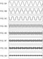
- FIGS 6A to 6H are graphs each illustrating a signal waveform.
- FIG. 6A illustrates the waveform of the excitation AC current i1
- FIG. 6B illustrates the waveform of the primary detection signal S1
- FIG. 6C illustrates the waveform of the secondary detection signal S2
- FIGS. 6D to 6H respectively illustrate the waveforms of a third harmonic, a fifth harmonic, a seventh harmonic, a ninth harmonic, and an eleventh harmonic, which are contained in the secondary detection signal S2.
- the solid line denotes the detection signal component
- the dashed line denotes the noise component.
- the excitation AC current i1 assumes a sine wave.
- both the detection signal component and noise component included in the primary detection signal S1 assume a sine wave, as illustrated in FIG. 6C .
- the detection signal component is converted to a non-sine wave using the magnetic field generation coil C2 and magnetic sensor 16, so that, as illustrated in FIG. 6C , the detection signal component included in the secondary detection signal S2 assumes a non-sine wave, while the noise component included in the secondary detection signal S2 assumes a sine wave.
- a large harmonic appears in the detection signal component, while substantially no harmonic appears in the noise component.
- the ratio (SN ratio) between the detection signal component and the noise component included in the primary detection signal S1 is 9.6 dB
- the SN ratios of the respective third harmonic, fifth harmonic, seventh harmonic, ninth harmonic, and eleventh harmonic contained in the secondary detection signal S2 are 11.1 dB, 15.3 dB, 14.7 dB, 13.3 dB, and 9.0 dB, respectively.
- the signal processing circuit 18 by extracting a predetermined harmonic component from the secondary detection signal S2 using the signal processing circuit 18, it is possible to take out the detection signal component caused due to magnetization change of the magnetic material P.
- the thus extracted detection signal component is output outside as a tertiary detection signal S3.
- the magnetic field measurement device 1 makes the magnetization M of the magnetic material P exhibit linear response based on the excitation AC magnetic field, while it selectively converts the detection signal component to a non-sine wave using the magnetic field generation coil C2 and magnetic sensor 16, so that it is possible not only to significantly reduce the amount of the excitation AC current i1 but also to ensure a sufficient SN ratio even though the frequency of the excitation AC current i1 is reduced to about 10 kHz.
- the primary detection signal S1 is converted to the secondary detection signal S2 using a physical device, thus preventing a delay that may occur when the primary detection signal S1 is directly subjected to signal processing. This enables magnetic particle imaging with respect to an object to be measured having a relatively large size like a human body.
Landscapes
- Physics & Mathematics (AREA)
- Health & Medical Sciences (AREA)
- Condensed Matter Physics & Semiconductors (AREA)
- General Physics & Mathematics (AREA)
- Engineering & Computer Science (AREA)
- Life Sciences & Earth Sciences (AREA)
- Nanotechnology (AREA)
- Chemical & Material Sciences (AREA)
- Nuclear Medicine, Radiotherapy & Molecular Imaging (AREA)
- Medical Informatics (AREA)
- General Health & Medical Sciences (AREA)
- Heart & Thoracic Surgery (AREA)
- Pathology (AREA)
- Molecular Biology (AREA)
- Surgery (AREA)
- Animal Behavior & Ethology (AREA)
- Biomedical Technology (AREA)
- Public Health (AREA)
- Veterinary Medicine (AREA)
- Biophysics (AREA)
- Radiology & Medical Imaging (AREA)
- Measuring Magnetic Variables (AREA)
- Measurement And Recording Of Electrical Phenomena And Electrical Characteristics Of The Living Body (AREA)
- Investigating Or Analyzing Materials By The Use Of Magnetic Means (AREA)
Abstract
Description
- The present invention relates to a magnetic field measurement device and, more particularly, to a magnetic field measurement device capable of being used for magnetic particle imaging.
- There is known a magnetic particle imaging device (see Non-Patent Document 1) as a magnetic field measurement device of a type that detects a magnetization change caused due to excitation of an object to be measured. The magnetic particle imaging device is provided with an excitation coil that applies an excitation AC magnetic field to an object to be measured containing magnetic particles and a magnetic sensor that detects a detection AC magnetic field generated by the magnetization change of the excited magnetic particles. The magnetic sensor is applied not only with the detection AC magnetic field but also with the excitation AC magnetic field, and when the magnetization change of the magnetic particles is made to exhibit a nonlinear response, a detection signal component and an excitation component (noise component) included in an output signal from the magnetic sensor can be separated from each other through signal processing.
- [Non-Patent Document 1] B. Gleich and J. Weizenecker, Nature, 435, 1214 (2005).
- However, in order to make the magnetization change of a magnetic material such as a magnetic particle exhibit nonlinear response, it is necessary to apply a very strong excitation AC magnetic field to an object to be measured. In addition, in order to detect the magnetization change made to exhibit nonlinear response, it is necessary to set the frequency of the excitation AC magnetic field to a high frequency of, e.g., 20 kHz or more. Therefore, when the size of an object to be measured is large to some extent, it is necessary to make an extremely large high-frequency current flow in the excitation coil, which, however, is impractical.
- It is therefore an object of the present invention to reduce, in a magnetic field measurement device of a type that detects a magnetization change caused due to excitation of an object to be measured, the current value and frequency of a current flowing in an excitation coil.
- A magnetic field measurement device according to the present invention includes: a first coil that applies an excitation AC magnetic field to an object to be measured including a magnetic material to make a magnetization change of the magnetic material exhibit linear response; a first magnetic sensor that detects a primary detection AC magnetic field caused due to the magnetization change of the magnetic material to generate a primary detection signal; a second coil that generates a secondary detection AC magnetic field based on the primary detection signal; and a second magnetic sensor that detects the secondary detection AC magnetic field to generate a secondary detection signal including a non-sine wave component.
- According to the present invention, the primary detection signal generated by the first magnetic sensor is converted back to a magnetic field, and the obtained magnetic field is detected by the second magnetic sensor, so that it is possible to obtain the secondary detection signal including a non-sine wave component without making the magnetization change of the magnetic material exhibit nonlinear response. This allows high-sensitivity detection of the magnetization change of the magnetic material even though the current value of a current flowing in the first coil is small and the frequency thereof is low.
- The magnetic field measurement device according to the present invention may further include a third coil that cancels the excitation AC magnetic field applied to the first magnetic sensor. This makes it possible to reduce a noise component included in the primary detection signal.
- The magnetic field measurement device according to the present invention may further include a signal processing circuit that detects a harmonic component included in the secondary detection signal. This makes it possible to remove a noise component included in the secondary detection signal.
- As described above, according to the present invention, in a magnetic field measurement device of a type that detects a magnetization change caused due to excitation of an object to be measured, the current value and frequency of a current flowing in an excitation coil can be reduced.
-
-
FIG. 1 is a schematic diagram for explaining the configuration of a magneticfield measurement device 1 according to an embodiment of the present invention. -
FIG. 2 is a schematic view for explaining the magnetization change of the magnetic material P. -
FIG. 3 is a circuit diagram of themagnetic sensor 16. -
FIG. 4 is a schematic graph for explaining the magnetization change of the magnetic material P, in which the vertical and horizontal axes represent a magnetization M and a magnetic field H, respectively. -
FIG. 5 is a schematic graph for explaining a change in the secondary detection signal S2, in which the vertical and horizontal axes represent a voltage V and a magnetic field H, respectively. -
FIGS 6A to 6H are graphs each illustrating a signal waveform.FIG. 6A illustrates the waveform of the excitation AC current i1,FIG. 6B illustrates the waveform of the primary detection signal S1,FIG. 6C illustrates the waveform of the secondary detection signal S2,FIGS. 6D to 6H respectively illustrate the waveforms of a third harmonic, a fifth harmonic, a seventh harmonic, a ninth harmonic, and an eleventh harmonic, which are contained in the secondary detection signal S2. - Hereinafter, preferred embodiments of the present invention will be described in detail with reference to the accompanying drawings.
-
FIG. 1 is a schematic diagram for explaining the configuration of a magneticfield measurement device 1 according to an embodiment of the present invention. - The magnetic
field measurement device 1 according to the present embodiment is a device that detects a magnetic material P in an object to be measured positioned in a measurement area A and includes, as illustrated inFIG. 1 ,magnets excitation circuit 13 connected to an excitation coil C1, and a detection coil C0 that detects a primary detection AC magnetic field caused due to a magnetization change of the magnetic material P. The magnetic material P may be a magnetic nanoparticle with nanosize. Using the magnetic nanoparticle as the magnetic material P allows a human body to be set as the object to be measured. - The
magnets magnets excitation circuit 13 is a circuit for making an excitation AC current i1 flow in the excitation coil C1, whereby an excitation AC magnetic field is applied to the measurement area A. The excitation AC current i1 has a sine waveform. As described later, the strength of the excitation AC magnetic field is set to a value making the magnetization change of the magnetic material P positioned in the measurement area A exhibit nonlinear response. The nonlinear response means that the magnetic material P undergoes a magnetization change in an unsaturated region. Thus, the nonlinear response may include not only a case where the magnetization change is completely linear, but also a case where it includes some nonlinear component so long as the magnetization change occurs in the unsaturated region. -
FIG. 2 is a schematic view for explaining the magnetization change of the magnetic material P. - In the example illustrated in
FIG. 2A , when an excitation magnetic field is applied to the magnetic material P, the magnetic material P itself, which has a magnetization M in a predetermined direction, rotates, with the result that the direction of the magnetization M changes. In the example illustrated inFIG. 2B , when an excitation magnetic field is applied to the magnetic material P, the magnetization M inside the magnetic material P rotates. In either case, application of the excitation magnetic field to the magnetic material P causes a change in the direction of the magnetization M of the magnetic material P. Further, both the rotation of the magnetic material P itself illustrated inFIG. 2A and rotation of the magnetization M inside the magnetic material P illustrated inFIG. 2B may occur by application of the excitation magnetic field. In the present embodiment, a change in the direction of the magnetization M caused by application of the excitation magnetic field to the magnetic material P is defined as "magnetization change". - The magnetization change of the magnetic material P generates a primary detection AC magnetic field. The primary detection AC magnetic field is detected by the detection coil C0 as a first magnetic sensor, and a primary detection signal S1 is generated. In the present embodiment, the above detection coil C0 is used as a magnetic sensor for detecting the primary detection AC magnetic field; however, the magnetic sensor for detecting the primary detection AC magnetic field is not limited to this, but a magnetic sensor using a magnetosensitive element may be employed. Although the excitation AC magnetic field is also applied to the magnetic material P existing outside the measurement area A, the magnetization change does not substantially occur since the direction of the magnetization M is fixed by the gradient DC magnetic field φ having a predetermined strength at the outside of the measurement area A. This allows the detection coil C0 to selectively detect the magnetization change of the magnetic material P positioned within the measurement area A.
- The excitation AC magnetic field applied to the detection coil C0 is canceled by a cancel coil C3. A cancel current i3 is made to flow in the cancel coil C3 by a
compensation circuit 14, whereby the excitation AC magnetic field applied to the detection coil C0 is canceled. However, it is difficult to completely cancel the excitation AC magnetic field applied to the detection coil C0 and, thus, a slight noise component originating from the excitation AC magnetic field is superimposed on the primary detection signal S1. - The primary detection signal S1 is input to an
amplifier circuit 15. Theamplifier circuit 15 is an analog circuit including a differential amplifier and a filter circuit and supplies a detection AC current i2 to a magnetic field generation coil C2 based on the primary detection signal S1. As a result, a secondary detection AC magnetic field is generated from the magnetic field generation coil C2. Theamplifier circuit 15 has substantially no delay since it is an analog circuit, so that a secondary detection AC magnetic field is generated in substantially real time in accordance with the primary detection AC magnetic field. The secondary detection AC magnetic field is detected by a secondmagnetic sensor 16, and a secondary detection signal S2 is generated. -
FIG. 3 is a circuit diagram of themagnetic sensor 16. - As illustrated in
FIG. 3 , themagnetic sensor 16 is constituted bymagnetosensitive elements 21 to 24 which are full-bridge connected. Themagnetosensitive elements 21 to 24 may be an element having high sensitivity even in a low frequency region and capable of being magnetically saturated, examples thereof including: magnetoresistive effect elements such as a TMR (Tunnel Magneto-Resistive effect) element, a GMR (Giant Magneto-Resistive effect) element, and an AMR (Anisotropic Magneto-Resistive effect) element; a hall element; and an MI (Magnetic Impedance) element. Themagnetic sensor 16 is configured such that the secondary detection AC magnetic field generated from the magnetic field generation coil C2 is applied in mutually opposite directions to themagnetosensitive elements magnetosensitive elements magnetic sensor 16. Themagnetic sensor 16 may be not only a sensor obtained by full-bridge connecting four magnetosensitive elements but also a sensor obtained by half-bridge connecting two magnetosensitive elements and a sensor using a single magnetosensitive element. - The secondary detection signal S2 is supplied to a
signal processing circuit 18 through anamplifier 17. Thesignal processing circuit 18 extracts a harmonic component included in the secondary detection signal S2 to generate a tertiary detection signal S3. The tertiary detection signal S3 is a final output signal of the magneticfield measurement device 1 according to the present embodiment and indicates the magnetization change of the magnetic material P positioned in the measurement area A. When an imaging device for imaging the obtained tertiary detection signal S3 is combined with the thus configured magneticfield measurement device 1, a magnetic particle imaging device can be constituted. - The configuration of the magnetic
field measurement device 1 according to the present embodiment has been described. The following describes the operation of the magneticfield measurement device 1 according to the present embodiment. - The
excitation circuit 13 makes the excitation AC current i1 flow in the excitation coil C1 such that the magnetization change of the magnetic material P positioned in the measurement area A exhibits linear response. That is, the amount of the excitation AC current i1 supplied to the excitation coil C1 is set to a value sufficiently smaller than an amount required for making the magnetization change of the magnetic material P exhibit nonlinear response. -
FIG. 4 is a schematic graph for explaining the magnetization change of the magnetic material P, in which the vertical and horizontal axes represent a magnetization M and a magnetic field H, respectively. - As illustrated in
FIG. 4 , when the amplitude of the magnetic field H is set to H1, the magnetization M of the magnetic material P is saturated to exhibit nonlinear response between the magnetization m1 and the magnetization m2 in the graph. In this case, a detection signal component included in the primary detection signal S1 assumes a non-sine wave. When the object to be measured has a size comparable to a human body, a magnetic field as strong as about 6 mT is required in order to make the magnetization M of the magnetic material P as a magnetic nanoparticle exhibit nonlinear response. On the other hand, when the amplitude of the magnetic field H is set to H2 (< H1), the magnetization M of the magnetic material P changes in the unsaturated region and thus exhibits linear response between the magnetization m3 and the magnetization m4 in the graph. In this case, the detection signal component included in the primary detection signal S1 is presented by a sine wave. - As described above, the amount of the excitation AC current i1 is reduced to an amount with which the magnetization change of the magnetic material P exhibits linear response, so that as compared with a case where the magnetization change of the magnetic material P exhibits nonlinear response, the amount of the excitation AC current i1 is significantly reduced. When the object to be measured has a size comparable to a human body, it is sufficient to set a magnetic field to, e.g., 0.1 mT in order to make the magnetization M of the magnetic material P as a magnetic nanoparticle exhibit linear response. That is, the amount of the excitation AC current i1 is reduced to 1/10 or less of the amount required for making the magnetization change of the magnetic material P exhibit nonlinear response.
- As described above, in the present embodiment, the magnetization change of the magnetic material P is made to exhibit linear response by the excitation coil C1, so that, in the primary detection signal S1 generated by the detection coil C0, the detection signal component originating from the primary detection AC magnetic field is presented by a sine wave. The primary detection signal S1 includes also a noise component originating from the excitation AC magnetic field that has not been canceled completely. However, this noise component is reduced to a sufficiently low level by the cancel coil C3, and thus the detection signal component is dominant. The primary detection signal S1 is converted to the detection AC current i2 by the
amplifier circuit 15, whereby the secondary detection AC magnetic field is generated from the magnetic field generation coil C2. The secondary detection AC magnetic field is detected by themagnetic sensor 16, and the secondary detection signal S2 is generated. -
FIG. 5 is a schematic graph for explaining a change in the secondary detection signal S2, in which the vertical and horizontal axes represent a voltage V and a magnetic field H, respectively. - As illustrated in
FIG. 5 , the amplitude of a detection signal component included in the secondary detection AC magnetic field is H3. The magneto-resistive effect of themagnetosensitive elements 21 to 24 is saturated with respect to a component having an amplitude of H3 in the secondary detection AC magnetic field, with the result that the voltage V of the secondary detection signal S2 exhibits nonlinear response between the voltage v1 and the voltage v2 in the graph. In this case, the detection signal component included in the secondary detection signal S2 assumes a non-sine wave. On the other hand, a noise component included in the secondary detection AC magnetic field is H4 (< H3). Themagnetosensitive elements 21 to 24 operate in the unsaturated region with respect to a component having an amplitude of H4 in the secondary detection AC magnetic field, with the result that the voltage V of the secondary detection signal S2 exhibits linear response between the voltage v3 and the voltage v4 in the graph. - In order to make the
magnetosensitive elements 21 to 24 exhibit nonlinear response based on the detection signal component and to make themagnetosensitive elements 21 to 24 exhibit linear response based on the noise component, a preliminary magnetic field measurement operation is performed in a state where the magnetic material P does not exist in the measurement area A, i.e., a state where no detection signal component is included, and then the gain of theamplifier circuit 15 and filter characteristics are adjusted so as to make themagnetosensitive elements 21 to 24 exhibit linear response based on the noise component originating from the excitation AC magnetic field. - As a result, the detection signal component included in the secondary detection AC magnetic field is converted to a non-sine wave component of the secondary detection signal S2, while the noise component included in the secondary detection AC magnetic field is converted to a sine wave component of the secondary detection signal S2. That is, although both the detection signal component and noise component included in the primary detection signal S1 assume a sine wave, they are separated into a non-sine wave component and a sine wave component, respectively, through conversion into a magnetic field using the magnetic field generation coil C2 and additional conversion into the secondary detection signal S2 using the
magnetic sensor 16. - The thus generated secondary detection signal S2 is supplied to the
signal processing circuit 18 through theamplifier 17. Thesignal processing circuit 18 extracts a harmonic component included in the secondary detection signal S2 to generate a tertiary detection signal S3. As described above, the detection signal component included in the secondary detection signal S2 is a non-sine wave component, so that a harmonic occurs. On the other hand, the noise component included in the secondary detection signal S2 is a sine wave component, a harmonic hardly occurs. Thus, by detecting a harmonic component included in the secondary detection signal S2, it is possible to selectively extract the detection signal component. -
FIGS 6A to 6H are graphs each illustrating a signal waveform.FIG. 6A illustrates the waveform of the excitation AC current i1,FIG. 6B illustrates the waveform of the primary detection signal S1,FIG. 6C illustrates the waveform of the secondary detection signal S2,FIGS. 6D to 6H respectively illustrate the waveforms of a third harmonic, a fifth harmonic, a seventh harmonic, a ninth harmonic, and an eleventh harmonic, which are contained in the secondary detection signal S2. InFIGS. 6B to 6H , the solid line denotes the detection signal component, and the dashed line denotes the noise component. - As illustrated in
FIG. 6A , the excitation AC current i1 assumes a sine wave. In the present embodiment, since the magnetization M of the magnetic material P is made to exhibit linear response by the excitation AC magnetic field, both the detection signal component and noise component included in the primary detection signal S1 assume a sine wave, as illustrated inFIG. 6C . However, the detection signal component is converted to a non-sine wave using the magnetic field generation coil C2 andmagnetic sensor 16, so that, as illustrated inFIG. 6C , the detection signal component included in the secondary detection signal S2 assumes a non-sine wave, while the noise component included in the secondary detection signal S2 assumes a sine wave. As a result, as illustrated inFIGS. 6D to 6H , a large harmonic appears in the detection signal component, while substantially no harmonic appears in the noise component. For example, when the ratio (SN ratio) between the detection signal component and the noise component included in the primary detection signal S1 is 9.6 dB, the SN ratios of the respective third harmonic, fifth harmonic, seventh harmonic, ninth harmonic, and eleventh harmonic contained in the secondary detection signal S2 are 11.1 dB, 15.3 dB, 14.7 dB, 13.3 dB, and 9.0 dB, respectively. - Thus, by extracting a predetermined harmonic component from the secondary detection signal S2 using the
signal processing circuit 18, it is possible to take out the detection signal component caused due to magnetization change of the magnetic material P. The thus extracted detection signal component is output outside as a tertiary detection signal S3. - As described above, the magnetic
field measurement device 1 according to the present embodiment makes the magnetization M of the magnetic material P exhibit linear response based on the excitation AC magnetic field, while it selectively converts the detection signal component to a non-sine wave using the magnetic field generation coil C2 andmagnetic sensor 16, so that it is possible not only to significantly reduce the amount of the excitation AC current i1 but also to ensure a sufficient SN ratio even though the frequency of the excitation AC current i1 is reduced to about 10 kHz. In addition, the primary detection signal S1 is converted to the secondary detection signal S2 using a physical device, thus preventing a delay that may occur when the primary detection signal S1 is directly subjected to signal processing. This enables magnetic particle imaging with respect to an object to be measured having a relatively large size like a human body. - While the preferred embodiment of the present disclosure has been described, the present disclosure is not limited to the above embodiment, and various modifications may be made within the scope of the present disclosure, and all such modifications are included in the present disclosure.
-
- 1
- magnetic field measurement device
- 11, 12
- magnet
- 13
- excitation circuit
- 14
- compensation circuit
- 15
- amplifier circuit
- 16
- magnetic sensor
- 17
- amplifier
- 18
- signal processing circuit
- 21-24
- magnetosensitive element
- A
- measurement area
- C0
- detection coil
- C1
- excitation coil
- C2
- magnetic field generation coil
- C3
- cancel coil
- P
- magnetic material
- S1
- primary detection signal
- S2
- secondary detection signal
- S3
- tertiary detection signal
- i1
- excitation AC current
- i2
- detection AC current
- i3
- cancel current
- φ
- gradient DC magnetic field
Claims (3)
- A magnetic field measurement device comprising:a first coil that applies an excitation AC magnetic field to an object to be measured including a magnetic material to make a magnetization change of the magnetic material exhibit linear response;a first magnetic sensor that detects a primary detection AC magnetic field caused due to the magnetization change of the magnetic material to generate a primary detection signal;a second coil that generates a secondary detection AC magnetic field based on the primary detection signal; anda second magnetic sensor that detects the secondary detection AC magnetic field to generate a secondary detection signal including a non-sine wave component.
- The magnetic field measurement device as claimed in claim 1, further comprising a third coil that cancels the excitation AC magnetic field applied to the first magnetic sensor.
- The magnetic field measurement device as claimed in claim 1 or 2, further comprising a signal processing circuit that detects a harmonic component included in the secondary detection signal.
Applications Claiming Priority (2)
| Application Number | Priority Date | Filing Date | Title |
|---|---|---|---|
| JP2021093177A JP7817691B2 (en) | 2021-06-02 | 2021-06-02 | Magnetic measurement device |
| PCT/JP2022/022105 WO2022255354A1 (en) | 2021-06-02 | 2022-05-31 | Magnetism measuring device |
Publications (2)
| Publication Number | Publication Date |
|---|---|
| EP4350377A1 true EP4350377A1 (en) | 2024-04-10 |
| EP4350377A4 EP4350377A4 (en) | 2025-07-23 |
Family
ID=84323415
Family Applications (1)
| Application Number | Title | Priority Date | Filing Date |
|---|---|---|---|
| EP22816100.6A Pending EP4350377A4 (en) | 2021-06-02 | 2022-05-31 | MAGNETISM MEASURING DEVICE |
Country Status (5)
| Country | Link |
|---|---|
| US (1) | US20240248156A1 (en) |
| EP (1) | EP4350377A4 (en) |
| JP (1) | JP7817691B2 (en) |
| CN (1) | CN117413196A (en) |
| WO (1) | WO2022255354A1 (en) |
Families Citing this family (1)
| Publication number | Priority date | Publication date | Assignee | Title |
|---|---|---|---|---|
| JP2024142025A (en) * | 2023-03-29 | 2024-10-10 | Tdk株式会社 | Magnetic sensor and magnetic measurement device equipped with the same |
Family Cites Families (3)
| Publication number | Priority date | Publication date | Assignee | Title |
|---|---|---|---|---|
| WO2011116229A2 (en) * | 2010-03-17 | 2011-09-22 | The Regents Of The University Of California | Magnetic particle imaging devices and methods |
| JP2014224741A (en) | 2013-05-16 | 2014-12-04 | 国立大学法人豊橋技術科学大学 | Magnetic particulate detecting device and magnetic particulate detecting method |
| US12287388B2 (en) * | 2020-04-16 | 2025-04-29 | Mitsubishi Electric Corporation | Magnetic particle imaging device |
-
2021
- 2021-06-02 JP JP2021093177A patent/JP7817691B2/en active Active
-
2022
- 2022-05-31 EP EP22816100.6A patent/EP4350377A4/en active Pending
- 2022-05-31 US US18/566,578 patent/US20240248156A1/en active Pending
- 2022-05-31 WO PCT/JP2022/022105 patent/WO2022255354A1/en not_active Ceased
- 2022-05-31 CN CN202280039677.9A patent/CN117413196A/en active Pending
Also Published As
| Publication number | Publication date |
|---|---|
| JP2022185470A (en) | 2022-12-14 |
| CN117413196A (en) | 2024-01-16 |
| JP7817691B2 (en) | 2026-02-19 |
| US20240248156A1 (en) | 2024-07-25 |
| WO2022255354A1 (en) | 2022-12-08 |
| EP4350377A4 (en) | 2025-07-23 |
Similar Documents
| Publication | Publication Date | Title |
|---|---|---|
| CN105022005B (en) | A kind of method, apparatus and system of raising SQUID Magnetic Sensor measurement sensitivities | |
| US8829901B2 (en) | Method of using a magnetoresistive sensor in second harmonic detection mode for sensing weak magnetic fields | |
| KR101593665B1 (en) | Spin torque-type magnetic sensor | |
| WO2003107017A1 (en) | Magnetic bridge type current sensor, magnetic bridge type current detecting method, and magnetic bridge for use in that sensor and detecting method | |
| WO2017077870A1 (en) | Magnetic field detection device and magnetic field detection method | |
| US10267867B2 (en) | Signal transmission/reception method for signal analysis in FMMD technology and apparatus using the same | |
| CN107315150A (en) | A kind of orthogonal basic mode fluxgate sensor | |
| US11269023B2 (en) | Magnetic field detection device and method of detecting magnetic field | |
| JP5116433B2 (en) | Magnetic detector for detecting variable magnetic fields | |
| CN202066953U (en) | Magnetic sensor | |
| JP2017062122A (en) | Magnetic field detector | |
| US20240248156A1 (en) | Magnetic field measurement device | |
| JP3962784B2 (en) | Current probe | |
| JP2000055998A (en) | Magnetic sensor device and current sensor device | |
| JP2010078401A (en) | Non-contact magnetic modulation type signal amplifier | |
| Tian et al. | Magnetic Flux Vertical Motion Modulation for 1/${f} $ Noise Suppression in Magnetoresistance Field Sensors Using MEMS Device | |
| JP2000056000A (en) | Magnetic sensor device and current sensor device | |
| JP3651268B2 (en) | Magnetic measurement method and apparatus | |
| Ripka et al. | AMR proximity sensor with inherent demodulation | |
| CN116965795B (en) | High-sensitivity magnetic particle imaging system and method | |
| GB2461207A (en) | Magnetic sensor with compensation for lead and coil resistance | |
| Doan et al. | Magnetization measurement system with giant magnetoresistance zero-field detector | |
| Tanaka et al. | 2D magnetic nanoparticle imaging using magnetization response second harmonic | |
| KR101094076B1 (en) | Permeability measuring device | |
| Trisnanto et al. | Low-concentration magnetic particle spectroscopy using gradiometric receive coil-coupled magnetoresistive sensor |
Legal Events
| Date | Code | Title | Description |
|---|---|---|---|
| STAA | Information on the status of an ep patent application or granted ep patent |
Free format text: STATUS: THE INTERNATIONAL PUBLICATION HAS BEEN MADE |
|
| PUAI | Public reference made under article 153(3) epc to a published international application that has entered the european phase |
Free format text: ORIGINAL CODE: 0009012 |
|
| STAA | Information on the status of an ep patent application or granted ep patent |
Free format text: STATUS: REQUEST FOR EXAMINATION WAS MADE |
|
| 17P | Request for examination filed |
Effective date: 20231221 |
|
| AK | Designated contracting states |
Kind code of ref document: A1 Designated state(s): AL AT BE BG CH CY CZ DE DK EE ES FI FR GB GR HR HU IE IS IT LI LT LU LV MC MK MT NL NO PL PT RO RS SE SI SK SM TR |
|
| DAV | Request for validation of the european patent (deleted) | ||
| DAX | Request for extension of the european patent (deleted) | ||
| A4 | Supplementary search report drawn up and despatched |
Effective date: 20250624 |
|
| RIC1 | Information provided on ipc code assigned before grant |
Ipc: G01R 33/12 20060101AFI20250617BHEP Ipc: A61B 5/0515 20210101ALI20250617BHEP Ipc: G01R 33/09 20060101ALI20250617BHEP |