EP4350155A1 - Befestigungsklammer, befestigungssystem und dachanordnung - Google Patents
Befestigungsklammer, befestigungssystem und dachanordnung Download PDFInfo
- Publication number
- EP4350155A1 EP4350155A1 EP23199143.1A EP23199143A EP4350155A1 EP 4350155 A1 EP4350155 A1 EP 4350155A1 EP 23199143 A EP23199143 A EP 23199143A EP 4350155 A1 EP4350155 A1 EP 4350155A1
- Authority
- EP
- European Patent Office
- Prior art keywords
- fastening
- roof
- locking
- support
- headliner
- Prior art date
- Legal status (The legal status is an assumption and is not a legal conclusion. Google has not performed a legal analysis and makes no representation as to the accuracy of the status listed.)
- Granted
Links
Images


Classifications
-
- F—MECHANICAL ENGINEERING; LIGHTING; HEATING; WEAPONS; BLASTING
- F16—ENGINEERING ELEMENTS AND UNITS; GENERAL MEASURES FOR PRODUCING AND MAINTAINING EFFECTIVE FUNCTIONING OF MACHINES OR INSTALLATIONS; THERMAL INSULATION IN GENERAL
- F16B—DEVICES FOR FASTENING OR SECURING CONSTRUCTIONAL ELEMENTS OR MACHINE PARTS TOGETHER, e.g. NAILS, BOLTS, CIRCLIPS, CLAMPS, CLIPS OR WEDGES; JOINTS OR JOINTING
- F16B2/00—Friction-grip releasable fastenings
- F16B2/20—Clips, i.e. with gripping action effected solely by the inherent resistance to deformation of the material of the fastening
- F16B2/22—Clips, i.e. with gripping action effected solely by the inherent resistance to deformation of the material of the fastening of resilient material, e.g. rubbery material
- F16B2/24—Clips, i.e. with gripping action effected solely by the inherent resistance to deformation of the material of the fastening of resilient material, e.g. rubbery material of metal
- F16B2/241—Clips, i.e. with gripping action effected solely by the inherent resistance to deformation of the material of the fastening of resilient material, e.g. rubbery material of metal of sheet metal
- F16B2/243—Clips, i.e. with gripping action effected solely by the inherent resistance to deformation of the material of the fastening of resilient material, e.g. rubbery material of metal of sheet metal internal, i.e. with spreading action
-
- B—PERFORMING OPERATIONS; TRANSPORTING
- B60—VEHICLES IN GENERAL
- B60J—WINDOWS, WINDSCREENS, NON-FIXED ROOFS, DOORS, OR SIMILAR DEVICES FOR VEHICLES; REMOVABLE EXTERNAL PROTECTIVE COVERINGS SPECIALLY ADAPTED FOR VEHICLES
- B60J7/00—Non-fixed roofs; Roofs with movable panels, e.g. rotary sunroofs
- B60J7/0007—Non-fixed roofs; Roofs with movable panels, e.g. rotary sunroofs moveable head-liners, screens, curtains or blinds for ceilings
-
- B—PERFORMING OPERATIONS; TRANSPORTING
- B60—VEHICLES IN GENERAL
- B60J—WINDOWS, WINDSCREENS, NON-FIXED ROOFS, DOORS, OR SIMILAR DEVICES FOR VEHICLES; REMOVABLE EXTERNAL PROTECTIVE COVERINGS SPECIALLY ADAPTED FOR VEHICLES
- B60J7/00—Non-fixed roofs; Roofs with movable panels, e.g. rotary sunroofs
-
- B—PERFORMING OPERATIONS; TRANSPORTING
- B60—VEHICLES IN GENERAL
- B60R—VEHICLES, VEHICLE FITTINGS, OR VEHICLE PARTS, NOT OTHERWISE PROVIDED FOR
- B60R13/00—Elements for body-finishing, identifying, or decorating; Arrangements or adaptations for advertising purposes
- B60R13/02—Internal Trim mouldings ; Internal Ledges; Wall liners for passenger compartments; Roof liners
- B60R13/0206—Arrangements of fasteners and clips specially adapted for attaching inner vehicle liners or mouldings
-
- B—PERFORMING OPERATIONS; TRANSPORTING
- B60—VEHICLES IN GENERAL
- B60R—VEHICLES, VEHICLE FITTINGS, OR VEHICLE PARTS, NOT OTHERWISE PROVIDED FOR
- B60R13/00—Elements for body-finishing, identifying, or decorating; Arrangements or adaptations for advertising purposes
- B60R13/02—Internal Trim mouldings ; Internal Ledges; Wall liners for passenger compartments; Roof liners
- B60R13/0212—Roof or head liners
-
- B—PERFORMING OPERATIONS; TRANSPORTING
- B60—VEHICLES IN GENERAL
- B60R—VEHICLES, VEHICLE FITTINGS, OR VEHICLE PARTS, NOT OTHERWISE PROVIDED FOR
- B60R13/00—Elements for body-finishing, identifying, or decorating; Arrangements or adaptations for advertising purposes
- B60R13/02—Internal Trim mouldings ; Internal Ledges; Wall liners for passenger compartments; Roof liners
- B60R13/0212—Roof or head liners
- B60R13/0231—Roof or head liners specially adapted for roofs with openings
-
- F—MECHANICAL ENGINEERING; LIGHTING; HEATING; WEAPONS; BLASTING
- F16—ENGINEERING ELEMENTS AND UNITS; GENERAL MEASURES FOR PRODUCING AND MAINTAINING EFFECTIVE FUNCTIONING OF MACHINES OR INSTALLATIONS; THERMAL INSULATION IN GENERAL
- F16B—DEVICES FOR FASTENING OR SECURING CONSTRUCTIONAL ELEMENTS OR MACHINE PARTS TOGETHER, e.g. NAILS, BOLTS, CIRCLIPS, CLAMPS, CLIPS OR WEDGES; JOINTS OR JOINTING
- F16B5/00—Joining sheets or plates, e.g. panels, to one another or to strips or bars parallel to them
- F16B5/06—Joining sheets or plates, e.g. panels, to one another or to strips or bars parallel to them by means of clamps or clips
- F16B5/0607—Joining sheets or plates, e.g. panels, to one another or to strips or bars parallel to them by means of clamps or clips joining sheets or plates to each other
- F16B5/0621—Joining sheets or plates, e.g. panels, to one another or to strips or bars parallel to them by means of clamps or clips joining sheets or plates to each other in parallel relationship
-
- F—MECHANICAL ENGINEERING; LIGHTING; HEATING; WEAPONS; BLASTING
- F16—ENGINEERING ELEMENTS AND UNITS; GENERAL MEASURES FOR PRODUCING AND MAINTAINING EFFECTIVE FUNCTIONING OF MACHINES OR INSTALLATIONS; THERMAL INSULATION IN GENERAL
- F16B—DEVICES FOR FASTENING OR SECURING CONSTRUCTIONAL ELEMENTS OR MACHINE PARTS TOGETHER, e.g. NAILS, BOLTS, CIRCLIPS, CLAMPS, CLIPS OR WEDGES; JOINTS OR JOINTING
- F16B5/00—Joining sheets or plates, e.g. panels, to one another or to strips or bars parallel to them
- F16B5/06—Joining sheets or plates, e.g. panels, to one another or to strips or bars parallel to them by means of clamps or clips
- F16B5/0607—Joining sheets or plates, e.g. panels, to one another or to strips or bars parallel to them by means of clamps or clips joining sheets or plates to each other
- F16B5/0621—Joining sheets or plates, e.g. panels, to one another or to strips or bars parallel to them by means of clamps or clips joining sheets or plates to each other in parallel relationship
- F16B5/0628—Joining sheets or plates, e.g. panels, to one another or to strips or bars parallel to them by means of clamps or clips joining sheets or plates to each other in parallel relationship allowing for adjustment parallel or perpendicular to the plane of the sheets or plates
-
- F—MECHANICAL ENGINEERING; LIGHTING; HEATING; WEAPONS; BLASTING
- F16—ENGINEERING ELEMENTS AND UNITS; GENERAL MEASURES FOR PRODUCING AND MAINTAINING EFFECTIVE FUNCTIONING OF MACHINES OR INSTALLATIONS; THERMAL INSULATION IN GENERAL
- F16B—DEVICES FOR FASTENING OR SECURING CONSTRUCTIONAL ELEMENTS OR MACHINE PARTS TOGETHER, e.g. NAILS, BOLTS, CIRCLIPS, CLAMPS, CLIPS OR WEDGES; JOINTS OR JOINTING
- F16B5/00—Joining sheets or plates, e.g. panels, to one another or to strips or bars parallel to them
- F16B5/12—Fastening strips or bars to sheets or plates, e.g. rubber strips, decorative strips for motor vehicles, by means of clips
- F16B5/123—Auxiliary fasteners specially designed for this purpose
Definitions
- the invention relates to a fastening clamp for fastening a shaped headliner to a vehicle roof, in particular a panoramic or sliding roof, with a base element which is plate-shaped, with two support elements arranged opposite one another and extending away from the base element and at least substantially towards one another, wherein on each support element there is arranged a locking element protruding from the support element for locking the fastening clamp to the shaped headliner or to the vehicle roof, which is held elastically displaceably at an end of the respective support element facing away from the base element and extends in the direction of the base element.
- the invention relates to a fastening system for fastening a molded headliner to a vehicle roof, in particular a panoramic or sliding roof, with a bearing element that can be fastened to the molded headliner or the vehicle roof and has a receptacle for the positive locking of a fastening clamp, and with a fastening clamp that is held or retained in a positive locking manner on the bearing element, wherein the fastening clamp is designed as described above.
- the invention relates to a roof arrangement for a vehicle, in particular a motor vehicle, with a vehicle roof, in particular a panoramic roof or sliding roof, which has a roof frame in which a roof opening is formed, and a glass roof element which extends over the roof opening, and with a shaped headliner which is fastened to an underside of the vehicle roof assigned to a vehicle interior by means of the fastening system described above.
- fastening clamps and systems of the type mentioned above are already known from the state of the art.
- the patent application EN 10 2008 052 965 A1 a fastening clip that works together with another fastening clip to connect a molded headliner to a panoramic roof.
- the fastening clip has locking elements that protrude inwards, i.e. are located between the support elements, between which a counter-locking element of the vehicle roof or the molded headliner can be inserted in order to be engaged behind by the locking elements.
- the invention is based on the object of creating an improved fastening clamp which enables improved play compensation and can nevertheless be implemented cost-effectively.
- the object underlying the invention is achieved by a fastening clip with the features of claim 1.
- the fastening clip according to the invention has the advantage that, due to an advantageous design of the fastening clip, it can be fastened directly to the headliner or the vehicle roof, in particular without the interposition of a counter-latching element, and that advantageous play compensation is ensured in a simple manner.
- the respective latching element has a latching lug at a distance from the base element for engaging behind an edge section of the headliner or the vehicle roof, and that the respective latching lug protrudes from the outside of the support element facing away from the opposite support element.
- the fastening clip according to the invention thus shifts the fastening point of the fastening clip on the headliner or the vehicle roof outwards, i.e. into an area outside the area of the fastening clip enclosed by the base element and support elements.
- the locking lug is located outside the support elements, a longitudinal displacement of the holder along the vehicle roof or the headliner is achieved with simple means.
- the locking lug not only ensures that the fastening clip is locked to the headliner, but also that height compensation can be achieved by elastic displacement of at least the locking elements.
- the height of the fastening clip is understood to mean the extension of the fastening clip perpendicular to the base element, for example along a mirror plane between the opposing support elements.
- the support elements each have two support legs arranged at a distance from one another, which are connected to one another, in particular in one piece, by a crossbar on the end facing away from the base element.
- the respective locking element is held on the crossbar between the adjacent support legs of the respective support element and in particular is formed in one piece with it.
- the elastic displaceability of the locking element is preferably ensured by an elastic deformation of the locking element, in particular in the transition to the support element.
- the foot element has two guide rails arranged parallel to one another, which each extend from one support element to the opposite support element and protrude laterally from the support elements for accommodation in a rail guide, for example as side edges.
- the advantageous development of the fastening clamp ensures that the foot element itself is slidably mounted on a counter element, such as the headliner or the vehicle roof, or in an intermediate bearing element. This advantageously ensures tolerance compensation between the headliner and the vehicle roof in a further direction.
- the guide rails extend transversely to the longitudinal extension of the locking receptacles, so that the fastening clamp can be moved in a first direction in the area of the locking receptacle, and in a second direction, transverse to the first direction, in the area of the base element.
- the support elements, at least one support leg of the respective support element, and the locking elements are each designed in strip form.
- the support elements and the locking elements thus have a rectangular cross-section with a small depth compared to their width.
- the support elements and the locking elements are advantageously designed to be elastically deformable themselves, so that the fastening clip as a whole can be advantageously mounted, in particular without damaging the fastening clip itself or the molded headliner or the vehicle roof during assembly.
- the support elements and locking elements are aligned in such a way that they are aligned parallel to one another in the width extension, so that they lie in the same bending plane or are deformable in the same plane.
- the respective locking element has a free end spaced apart from the base element.
- the respective locking element is thus held at one end to the associated support element and is designed to swing freely at the other end, with the freely swinging end being assigned to the base element but at a distance from it. This ensures an advantageously large displacement path of the respective locking element.
- the elastic bearing held only at one end ensures that the locking element can be moved with little effort, so that the mounting of the fastening clamp can also be carried out without great effort.
- the respective free end has a holding element which extends parallel to the foot section at least when the fastening clip is not under load.
- the holding element or the end section achieves an advantageous alignment of the fastening clip on the headliner or the vehicle roof with respect to the foot element, which in particular achieves a secure and robust support of the headliner or the vehicle roof on the end section.
- the support elements are formed in one piece with the foot element. This ensures a robust connection between the support element and Foot element is created and on the other hand enables cost-effective production.
- the support elements preferably have at least one bend in their course. The bend gives the respective support element in particular a preferred rocking direction and/or an alignment, in particular an insertion bevel, which facilitates the insertion of the support elements and thus the fastening clip as a whole into the opening of the roof liner or the molded roof liner.
- the locking elements are formed at one end in one piece with the respective support element.
- Each of the locking elements is thus formed in one piece with the support element assigned to it. If the support elements are also formed in one piece with the base element, the locking elements are formed in one piece with both the support elements and the base element. This offers a particularly advantageous and cost-effective embodiment of the fastening clamp.
- the locking elements are formed integrally with the base element at the other end.
- the locking elements are integrally connected to the base element at the end facing the base element.
- the locking elements do not have a free end with a holding element, but instead merge integrally into the base element. This increases the stability and robustness of the fastening clamp overall.
- the respective locking element is formed integrally with the support element at one end and integrally with the base element at the other end, particularly high locking forces can be achieved, which ensure that the molded headliner is permanently and securely locked to the vehicle roof.
- the fastening clamp is designed as a stamped and bent part, which reduces manufacturing costs and assembly effort.
- the free ends of the support elements rest against one another and/or are fastened to one another. This advantageously increases the robustness, in particular the rigidity, of the fastening clamp.
- one of the free ends of the support elements i.e. at the end facing away from the base element, has a bending tab that encompasses the free end of the other of the support elements. This ensures a positive connection between the free ends of the support elements, which makes the fastening clamp robust and guarantees a long service life.
- the bending tab also means that a material connection, such as welding or soldering the free ends together, can be dispensed with.
- the fastening system according to the invention with the features of claim 12 is characterized by the inventive design of the fastening clamp. This results in the advantages already mentioned.
- the fastening clamp with its guide rails is or can be arranged so that it can move in a rail guide of the bearing element.
- the bearing element thus forms, together with the base element, a sliding guide for the fastening clamp, by means of which assembly or manufacturing tolerances of the headliner and/or vehicle roof can be compensated for in an advantageous manner in at least one sliding direction.
- the sliding direction of the fastening clamp in the bearing element is aligned transversely to a sliding direction of the holding elements or the locking receptacles on the vehicle roof or the molded headliner. Since the side edges or guide rails of the foot element extend in particular transversely to the longitudinal extension of the locking receptacles, this results in an advantageous compensation option for the fastening system in an X-Y plane. In the Z direction or in height, an advantageous tolerance compensation is preferably achieved through the elastic deformability of the locking elements and in particular also of the support elements.
- the roof arrangement according to the invention with the features of claim 15 is characterized by the inventive design of the fastening system.
- the bearing element is attached to the vehicle roof or to the headliner, for example glued, welded, clamped or held in a form-fitting manner, and the fastening clamp with the locking receptacles is attached to the vehicle roof or the headliner in the manner described above.
- FIG. 1 shows a simplified longitudinal sectional view of an advantageous roof arrangement 1 for a motor vehicle not shown in detail here.
- the roof arrangement 1 has a vehicle roof 2 which has a roof frame 3 with a roof opening 4 formed thereon and arranged centrally, particularly in the transverse extension.
- the roof opening 4 is covered or filled by a glass roof element 5 to form a panoramic glass roof.
- the glass roof element 5 preferably rests on the roof frame 3 at its outer edge.
- the roof arrangement 1 also has a molded headliner 6, which is arranged on an underside 7 of the vehicle roof 2 facing the interior of the motor vehicle.
- the molded headliner 6 serves in particular to cover the body parts, which are usually made of metal and form the roof frame, and to provide noise protection or sound insulation as well as thermal insulation for people in the interior of the motor vehicle.
- the molded headliner 6 lies essentially flat against the underside 7 of the vehicle roof 2 and extends up to the glass roof element 5.
- a fastening system 8 is provided, which enables simple assembly with just a few steps and yet ensures a long service life and a firm connection between the molded headliner and the vehicle roof.
- FIG 2 shows a perspective view of an advantageous embodiment of the fastening system 8.
- This has a bearing element 9, which is essentially plate-shaped and can be placed with a bottom side 10 on the headliner or the vehicle roof and can be fastened thereto, for example by screwing, gluing, soldering, caulking, locking or the like.
- the bearing element 9 has on its an insertion receptacle 12 on the upper side 11 facing away from the underside 10.
- the bearing element 9 has a flat support surface 13 on the upper side 11, which is partially covered on opposite side edges by longitudinally extending webs 14, so that there is a distance between the webs 14 and the support surface 13.
- the bearing element 9 forms a rail guide 15 through the support surface 13 and the web elements 14.
- the fastening system 8 further comprises a fastening clamp 16 which is held on the bearing element 9 by means of the rail guide 15.
- the fastening clamp 16 comprises a foot element 17 which is plate-shaped, i.e. essentially flat.
- the plate-shaped foot element 17 comprises two opposite side edges 18 which serve as guide rails 19 to be slidably mounted in the rail guide 15.
- the fastening clamp 16 is thus mounted with the foot element 17 in the insertion receptacle 12 so as to be longitudinally slidable, as indicated by a double arrow 20 in Figure 2 shown.
- Two support elements 21, 22 are arranged between the side edges 18.
- the support elements 21, 22 protrude from the foot section 17 and run towards each other, so that the fastening clamp 16 is triangular in shape when viewed from the side.
- the free ends of the support elements 21, 22 facing away from the foot element 17 rest against each other.
- the support element 21 also has a bending tab 23 at its free end, which partially surrounds the free end of the support element 22, whereby the support elements 21, 22 are mechanically connected to each other at their free ends.
- the support elements 21, 22 are formed in one piece with the foot element 17.
- the entire fastening clamp 16 is formed in one piece and in particular is manufactured as a stamped and bent part.
- the support elements 21, 22 also have a frame-like structure or shape.
- Each of the support elements 21, 22 has two strip-shaped support legs, which are formed on the foot element 17 at one end and are connected to one another at the other end by a crossbar, wherein in the present embodiment the crossbar of the support element 21 has or co-forms the previously mentioned bending tab 23.
- a locking element 24, 25 is arranged on each support element 21, 22.
- the locking elements 24, 25 are designed in the form of bending tabs or locking tongues and are attached at one end to the respective crosspiece of the support element 21 or 22 are formed in one piece.
- the locking elements 24, 25 are thus located between the support legs of the support elements 21, 22 and extend longitudinally parallel to these from the respective free end of the support elements 21, 22 in the direction of the foot element 17.
- the locking elements each have a locking lug 26, 27 on their free end section facing the foot element 17.
- the locking elements 24, 25 have a V- or U-shaped profile at their free end, seen in longitudinal section, so that a recess is formed in the respective locking element 24, 25, which forms the locking lug 26, 27 as an element protruding from the recess.
- the locking elements 24, 25 are designed in such a way that they protrude outwards or laterally from the respective support element 21, 22.
- the sides of the support elements 21, 22 facing away from one another are referred to as outer sides.
- the locking elements 24, 25 now protrude from these, in particular in such a way that the recesses adjoining the locking lugs 26, 27, which form locking receptacles, are located completely outside the support elements 21, 22 or at a distance from the outer surfaces of the support elements 21, 22.
- the one-piece design ensures that the locking elements 24, 25 can be moved towards one another under elastic deformation. If the fastening clamp 16 is inserted into a rectangular opening in the headliner 6 or the vehicle roof 2, for example, whose clear width is narrower than the distance between the locking receptacles, the locking elements 24, 25 spring in or towards one another when inserted into the opening until the edge of the opening comes to rest in the locking receptacles.
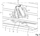
- Figure 3 shows a perspective detailed view of an assembled state of the fastening system 8 on the roof arrangement 1.
- the bearing element 9 is placed with the underside 10 on the molded headliner 6 and fastened to it.
- the fastening clamp 16 with the foot element 17 is inserted into the rail guide 15 and mounted so that it can be moved longitudinally.
- the fastening clamp 16 with the support elements 21, 22 is inserted into a rectangular opening 28 in the vehicle roof 2, in particular in the area of the frame 3, the clear width of the opening 28 being smaller than the width of the fastening clamp 16 in the area of the locking receptacles as seen in the sliding direction of the rail guide 15.
- the vehicle roof 2 reaches the area of the locking receptacles, so that the locking elements 24, 25 are again partially displaced outwards due to their own elasticity, so that the vehicle roof 2 is held in the locking receptacles in a form-fitting manner, whereby the pre-tension of the locking elements 24, 25 ensures a secure
- the height of the locking receptacles is only slightly higher than the height of the vehicle roof 2 in the fastening area, so that the edge area of the opening 28 can be securely accommodated in the respective locking receptacle, as in Figure 3 shown.
- FIG 4 shows a simplified side view of the roof arrangement 1 in the area of the fastening system 8 or the fastening clamp 16. It can be seen that the free ends of the locking elements form holding elements 29, 30 which engage behind the vehicle roof 2.
- the fastening clamp 16 also allows tolerance compensation in the Z or height direction, as indicated by a double arrow 31 in Figure 4 As the opening 28 is wider than the fastening clamp 16 or the support elements 21, 22, the fastening clamp 16 is mounted in the opening 28 so as to be longitudinally displaceable, as shown by a double arrow 32 in Figure 3 shown.
- the displacement or displaceability according to arrow 33 is transverse to the displacement according to arrow 20, which is formed by the rail guide 15 and the foot element 17.
- the advantageous fastening clamp 16 ensures tolerance compensation both in height and in a plane perpendicular to the height.
- the advantageous fastening system 8 offers simple assembly.
- Figure 3 and 4 The embodiment shown relates to an arrangement of the fastening system 8 in which the bearing element 9 rests on the molded headliner 6 and passes through an opening 28 of the vehicle roof 3, as in Figure 1 shown on the left side, is provided according to a further embodiment, as shown in Figure 1 On the right side it is shown that the bearing element is formed on the vehicle roof 3 and the opening 28 in the molded headliner 6.
- the fastening clamp 16 can be fastened to a separate bearing element 9, a molded headliner 6 or the vehicle roof 2, according to a further embodiment, it is provided that the insertion receptacle 12 or the rail guide 15 is arranged or formed directly in or on the molded headliner 6 or on the vehicle roof 2, so that the fastening clamp 16 can be fastened or is fastened directly to the vehicle roof 2 or the molded headliner 6.
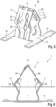
- Figures 5 and 6 relate to a second embodiment of the fastening clamp 16.
- the respective locking element 24, 25 is connected at one end in one piece with the respective support element 21, 22 and at the other end in one piece with the foot element 17.
- Figure 5 shows the fastening clip 16 in a perspective view.
- the locking elements 24, 25 therefore have no free end or no free end section.
- the locking lugs 26, 27 are essentially formed as in the previous embodiment by bending or deforming the respective locking element 24, 25 in its longitudinal extension.
- a recess or locking receptacle is formed in the respective locking element 24, 25 between the respective locking lug 26, 27 and the foot element 17. This recess then does not end in the holding element 30 extending parallel and at a distance from the foot element, but merges integrally into the foot element 17.
- the respective locking element 24, 25 thus has a zigzag-shaped longitudinal profile in particular.
- the shape of the support elements also differs from the previous embodiment.
- the support elements 21, 22 have an additional bend so that they have an s-shaped course.
- the bending points are offset from the bending points of the associated locking elements 24, 25 in relation to the height of the fastening clamp 16 so that the support elements 21, 22 and the locking elements 24, 25 are elastically bent at different points during assembly.
- the support elements also have an s-shape in the longitudinal direction, an advantageous force-reduced assembly is possible despite the one-piece design of the locking elements 24, 25 at both ends with the support elements 21, 22 on the one hand and the foot element 17 on the other.
- the locking elements 24, 25 also each have a stiffening element 33, 34, by means of which the elasticity of the locking elements 24, 25 is reduced in the area between the locking lug 26, 27 and the upper cross section of the respective support element 21, 22.
- the respective stiffening element 33, 34 is designed as a trough-shaped formation that bulges outwards from the respective locking element 24, 25.
- the stiffening elements 33, 34 are designed as bulges of the locking elements 24, 25 in the section between the locking lugs 26, 27 and the end associated with the support element.
- stiffening elements 33, 34 extend up to the respective locking lug 26, 27 in such a way that they form the locking lug 26, 27 in sections and thereby form a lateral projection that extends beyond the actual locking lug 26, 27, as in particular in Figure 6 shown.
- Figure 6 shows a cross-section through the Roof arrangement 1 with the fastening clamp 16 according to the embodiment of Figure 5 , whereby the cutting plane lies in the middle of the fastening clamp 16, so that it passes through the locking elements 24, 25 centrally.
- stiffening elements 33, 34 protrude laterally in the area of the locking lugs 26, 27, they also form a retaining projection that engages behind the vehicle roof 2 or the headliner 6 further than the actual locking lug 26, 27 and in particular has a less steep incline to the plane of the headliner or the vehicle roof 2, making it more difficult to pull the fastening clip 16 out of the roof opening 4. This ensures simple assembly and more difficult disassembly, or increased safety against the fastening clip 16 becoming accidentally loose.
Landscapes
- Engineering & Computer Science (AREA)
- Mechanical Engineering (AREA)
- General Engineering & Computer Science (AREA)
- Vehicle Interior And Exterior Ornaments, Soundproofing, And Insulation (AREA)
- Connection Of Plates (AREA)
- Body Structure For Vehicles (AREA)
Abstract
Description
- Die Erfindung betrifft eine Befestigungsklammer zur Befestigung eines Formhimmels an einem Fahrzeugdach, insbesondere Panorama- oder Schiebedach, mit einem Fußelement, das plattenförmig ausgebildet ist, mit zwei sich einander gegenüberliegend angeordneten und von dem Fußelement weg und zumindest im Wesentlichen aufeinander zu erstreckenden Stützelementen, wobei an jedem Stützelement ein von dem Stützelement vorstehendes Rastelement zur Verrastung der Befestigungsklammer an dem Formhimmel oder an dem Fahrzeugdach angeordnet ist, das an einem von dem Fußelement abgewandten Ende des jeweiligen Stützelements elastisch verlagerbar gehalten ist und sich in Richtung des Fußelements erstreckt.
- Weiterhin betrifft die Erfindung ein Befestigungssystem zum Befestigen eines Formhimmels an einem Fahrzeugdach, insbesondere Panorama- oder Schiebedach, mit einem an dem Formhimmel oder dem Fahrzeugdach befestigbaren Lagerelement, das eine Aufnahme zur formschlüssigen Arretierung einer Befestigungsklammer aufweist, und mit einer Befestigungsklammer, die formschlüssig an dem Lagerelement gehalten oder haltbar ist, wobei die Befestigungsklammer wie vorstehend beschrieben ausgebildet ist.
- Außerdem betrifft die Erfindung eine Dachanordnung für ein Fahrzeug, insbesondere Kraftfahrzeug, mit einem Fahrzeugdach, insbesondere Panoramadach oder Schiebedach, das einen Dachrahmen, in welchem eine Dachöffnung ausgebildet ist, und ein Glasdachelement aufweist, das sich über die Dachöffnung erstreckt, und mit einem Formhimmel, der an einer einem Fahrzeuginnenraum zugeordneten Unterseite des Fahrzeugdachs durch das obenstehend beschriebene Befestigungssystem befestigt ist.
- Befestigungsklammern und -systeme der eingangs genannten Art sind aus dem Stand der Technik bereits bekannt. So offenbart beispielsweise die Patentanmeldung
DE 10 2008 052 965 A1 eine Befestigungsklammer, die mit einer weiteren Befestigungsklammer zur Verbindung eines Formhimmels an einem Panoramadach zusammenwirkt. Dabei weist die Befestigungsklammer nach innen vorstehende, also zwischen den Stützelementen liegende Rastelemente auf, zwischen welchen ein Gegenrastelement des Fahrzeugdachs oder des Formhimmels einführbar ist, um von den Rastelementen hintergriffen zu werden. - Der Erfindung liegt die Aufgabe zugrunde, eine verbesserte Befestigungsklammer zu schaffen, die einen verbesserten Spielausgleich ermöglicht und dennoch kostengünstig realisierbar ist.
- Die der Erfindung zugrundeliegende Aufgabe wird durch eine Befestigungsklammer mit den Merkmalen des Anspruchs 1 gelöst. Die erfindungsgemäße Befestigungsklammer hat den Vorteil, dass durch eine vorteilhafte Ausbildung der Befestigungsklammer diese zum einen direkt an dem Formhimmel oder dem Fahrzeugdach befestigbar ist, insbesondere ohne Zwischenschaltung eines Gegenrastelements, und dass ein vorteilhafter Spielausgleich auf einfache Art und Weise gewährleistet wird. Erfindungsgemäß ist hierzu vorgesehen, dass das jeweilige Rastelement beabstandet zu dem Fußelement eine Rastnase zum Hintergreifen eines Randabschnitts des Formhimmels oder des Fahrzeugdachs aufweist, und dass die jeweilige Rastnase von der von dem gegenüberliegenden Stützelement abgewandten Außenseite des Stützelements vorsteht. Durch die erfindungsgemäße Befestigungsklammer wird somit die Befestigungsstelle der Befestigungsklammer an dem Formhimmel oder dem Fahrzeugdach nach außen verlagert, also in einen Bereich außerhalb des durch Fußelement und Stützelemente eingeschlossenen Bereichs der Befestigungsklammer. Dadurch kann die Befestigungsklammer insbesondere direkt in eine Öffnung des Formhimmels oder des Fahrzeugdachs eingeschoben und darin verrastet werden. Dadurch, dass die Rastnase außerhalb der Stützelemente liegt, ist eine Längsverschiebung der Aufnahme entlang des Fahrzeugdachs oder des Formhimmels mit einfachen Mitteln realisiert. Darüber hinaus gewährleistet die Rastnase nicht nur, dass die Befestigungsklammer an dem Formhimmel verrastet ist, sondern dass auch ein Höhenausgleich durch die elastische Verlagerung zumindest der Rastelemente erfolgen kann. Unter der Höhe der Befestigungsklammer wird dabei die Erstreckung der Befestigungsklammer senkrecht zu dem Fußelement, beispielsweise entlang einer Spiegelebene zwischen den einander gegenüberliegenden Stützelementen verstanden. Vorzugsweise weisen die Stützelemente jeweils zwei beabstandet zueinander angeordnete Stützschenkel auf, die durch einen Quersteg auf dem von dem Fußelement abgewandten Ende miteinander insbesondere einstückig verbunden sind. Besonders bevorzugt ist das jeweilige Rastelement an dem Quersteg zwischen den benachbarten Stützschenkeln des jeweiligen Stützelements gehalten und insbesondere einstückig mit diesem ausgebildet. Die elastische Verlagerbarkeit des Rastelements wird dabei bevorzugt durch eine elastische Verformung des Rastelements, insbesondere im Übergang zu dem Stützelement gewährleistet.
- Gemäß einer bevorzugten Weiterbildung der Erfindung weist das Fußelement zwei parallel zueinander angeordnete Führungsschienen auf, die sich jeweils von einem Stützelement zu dem gegenüberliegenden Stützelement erstrecken und von den Stützelementen seitlich zur Aufnahme in einer Schienenführung beispielsweise als Seitenränder vorstehen. Durch die vorteilhafte Weiterbildung der Befestigungsklammer wird erreicht, dass das Fußelement selbst verschiebbar an einem Gegenelement, wie beispielsweise dem Formhimmel oder dem Fahrzeugdach oder in einem dazwischenliegenden Lagerelement verschiebbar gelagert ist. Dadurch wird ein Toleranzausgleich zwischen Formhimmel und Fahrzeugdach in eine weitere Richtung in vorteilhafter Art und Weise gewährleistet. Insbesondere erstrecken sich die Führungsschienen quer zur Längserstreckung der Rastaufnahmen, sodass die Befestigungsklammer im Bereich der Rastaufnahme in eine erste Richtung verschiebbar ist, im Bereich des Fußelements in eine zweite, quer zur ersten Richtung liegende Richtung.
- Gemäß einer bevorzugten Weiterbildung der Erfindung sind die Stützelemente, zumindest ein Stützschenkel des jeweiligen Stützelement, und die Rastelemente jeweils streifenförmig ausgebildet. Somit weisen die Stützelemente und die Rastelemente einen rechteckförmigen Querschnitt mit einer im Vergleich zu seiner Breite kleinen Tiefe auf. Dadurch sind die Stützelemente und die Rastelementen in vorteilhafter Weise selbst elastisch verformbar ausgebildet, sodass die Befestigungsklammer insgesamt vorteilhaft montierbar ist, insbesondere ohne die Befestigungsklammer selbst oder den Formhimmel oder das Fahrzeugdach bei der Montage zu beschädigen. Insbesondere sind die Stützelemente und Rastelemente dabei derart ausgerichtet, dass sie in Breitenerstreckung parallel zueinander ausgerichtet sind, sodass sie in derselben Biegeebene liegen, beziehungsweise in derselben Ebene verformbar sind.
- Gemäß einer bevorzugten Ausführungsform weist das jeweilige Rastelement ein freies Ende beabstandet zu dem Fußelement auf. Damit ist das jeweilige Rastelement einendig an dem zugeordneten Stützelement gehalten und anderendig frei schwingend ausgebildet, wobei das freischwingende Ende dem Fußelement zugeordnet ist, jedoch beabstandet zu diesem liegt. Dadurch ist ein vorteilhaft großer Verlagerungsweg des jeweiligen Rastelements gewährleistet. Darüber hinaus wird durch die lediglich einendig gehaltene elastische Lagerung gewährleistet, dass das Rastelement mit geringem Kraftaufwand verlagerbar ist, sodass die Montage der Befestigungsklammer ebenfalls ohne hohen Kraftaufwand erfolgen kann.
- Weiterhin ist bevorzugt vorgesehen, dass das jeweilige freie Ende ein Halteelement aufweist, das sich zumindest im unbelasteten Zustand der Befestigungsklammer parallel zu dem Fußabschnitt erstreckt. Durch das Halteelement beziehungsweise durch den Endabschnitt wird eine vorteilhafte Ausrichtung der Befestigungsklammer an dem Formhimmel oder dem Fahrzeugdach mit Bezug auf das Fußelement erreicht, die insbesondere eine sichere und robuste Auflage des Formhimmels oder des Fahrzeugdachs auf dem Endabschnitt erzielt.
- Weiterhin ist bevorzugt vorgesehen, dass die Stützelemente einstückig mit dem Fußelement ausgebildet sind. Dadurch ist zum einen eine robuste Verbindung zwischen Stützelement und Fußelement geschaffen, und zum anderen eine kostengünstige Herstellung ermöglicht. Vorzugsweise weisen die Stützelemente in ihren Verlauf wenigstens eine Biegung auf. Durch die Biegung erhält das jeweilige Stützelement insbesondere eine Vorzugswiegerichtung und/oder eine Ausrichtung, insbesondere Einführschräge, die das Einführen der Stützelemente und damit der Befestigungsklammer insgesamt in die Öffnung des Dachhimmels oder des Formhimmels erleichtert.
- Weiterhin ist bevorzugt vorgesehen, dass die Rastelemente einendig einstückig mit dem jeweiligen Stützelement ausgebildet sind. Dabei ist somit jedes der Rastelemente einstückig mit dem ihm zugeordneten Stützelement ausgebildet. Sind auch die Stützelemente einstückig mit dem Fußelement ausgebildet, sind die Rastelemente einstückig sowohl mit den Stützelementen als auch mit dem Fußelement ausgebildet. Hierdurch ist eine besonders vorteilhafte und kostengünstige Ausführungsform der Befestigungsklammer geboten.
- Vorzugsweise sind die Rastelemente anderendig einstückig mit dem Fußelement ausgebildet. Damit sind die Rastelemente an dem dem Fußelement zugewandten Ende einstückig mit dem Fußelement verbunden. In diesem Fall weisen die Rastelemente also kein freies Ende mit einem Halteelement auf, sondern gehen stattdessen in das Fußelement einstückig über. Hierdurch wird die Stabilität und Robustheit der Befestigungsklammer insgesamt erhöht. Insbesondere können dadurch, dass das jeweilige Rastelement einendig einstückig mit dem Stützelement und anderendig einstückig mit dem Fußelement ausgebildet ist, besonders hohe Rastkräfte erzielt werden, die eine dauerhaft sichere Arretierung des Formhimmels an dem Fahrzeugdach gewährleisten.
- Besonders bevorzugt ist die Befestigungsklammer als Stanzbiegeteil ausgebildet, wodurch Herstellungskosten und Montageaufwand reduziert werden.
- Gemäß einer bevorzugten Weiterbildung der Erfindung liegen die freien Enden der Stützelemente aneinander an und/oder sind aneinander befestigt. Dadurch wird die Robustheit, insbesondere eine Steifigkeit der Befestigungsklammer in vorteilhafter Weise erhöht.
- Gemäß einer bevorzugten Weiterbildung der Erfindung weist eines der freien Enden der Stützelemente, also an dem von dem Fußelement abgewandten Ende, eine Biegelasche auf, die das freie Ende des anderen der Stützelemente umgreift. Dadurch ist eine formschlüssige Verbindung der freien Enden der Stützelemente aneinander gewährleistet, wodurch die Befestigungsklammer robust ausgebildet ist und eine hohe Lebensdauer garantiert. Durch die Biegelasche kann darüber hinaus auf ein stoffschlüssiges Verbinden, wie beispielsweise ein Verschweißen oder Verlöten der freien Enden miteinander verzichtet werden.
- Das erfindungsgemäße Befestigungssystem mit den Merkmalen des Anspruchs 12 zeichnet sich durch die erfindungsgemäße Ausbildung der Befestigungsklammer aus. Es ergeben sich hierdurch die bereits genannten Vorteile.
- Insbesondere ist die Befestigungsklammer mit ihren Führungsschienen in einer Schienenführung des Lagerelements verschiebbar angeordnet oder anordenbar. Das Lagerelement bildet somit zusammen mit dem Fußelement eine Schiebeführung für die Befestigungsklammer, durch welche Montage- oder Herstellungstoleranzen von Formhimmel und/oder Fahrzeugdach in zumindest eine Schieberichtung in vorteilhafter Art und Weise ausgeglichen werden können.
- Weiterhin ist bevorzugt vorgesehen, dass die Schieberichtung der Befestigungsklammer im Lagerelement quer zu einer Schieberichtung der Halteelemente beziehungsweise der Rastaufnahmen an dem Fahrzeugdach oder dem Formhimmel ausgerichtet ist. Da sich die Seitenränder beziehungsweise Führungsschienen den Fußelements insbesondere quer zu der Längserstreckung der Rastaufnahmen erstrecken, ergibt sich somit eine vorteilhafte Ausgleichsmöglichkeit des Befestigungssystems in einer X-Y-Ebene. In Z-Richtung beziehungsweise in der Höhe wird bevorzugt ein vorteilhafter Toleranzausgleich durch die elastische Verformbarkeit der Rastelemente und insbesondere auch der Stützelemente erzielt.
- Die erfindungsgemäße Dachanordnung mit den Merkmalen des Anspruchs 15 zeichnet sich durch die erfindungsgemäße Ausbildung des Befestigungssystems aus. Es ergeben sich dabei die bereits genannten Vorteile. Insbesondere ist das Lagerelement an dem Fahrzeugdach oder an dem Formhimmel befestigt, beispielsweise verklebt, verschweißt, verklemmt oder formschlüssig gehalten, und die Befestigungsklammer mit den Rastaufnahmen an dem Fahrzeugdach oder dem Formhimmel auf die oben beschriebene Art und Weise. Es ergibt sich dadurch der bereits genannte vorteilhafte Toleranzausgleich bei minimalen Herstellungskosten und einer hohen Robustheit des Gesamtsystems.
- Weitere Vorteile und bevorzugte Merkmale und Merkmalskombinationen ergeben sich insbesondere aus dem zuvor Beschriebenen sowie aus den Ansprüchen. Im Folgenden soll die Erfindung anhand der Zeichnung näher erläutert werden. Dazu zeigen
- Figur 1
- eine vorteilhafte Dachanordnung in einer vereinfachten Schnittdarstellung,
- Figur 2
- ein vorteilhaftes Befestigungssystem der Dachanordnung gemäß einem ersten Ausführungsbeispiel in einer perspektivischen Darstellung,
- Figur 3
- die Dachanordnung mit dem Befestigungssystem in einer vorteilhaften perspektivischen Darstellung,
- Figur 4
- die Dachanordnung mit dem Befestigungssystem in einer vorteilhaften Seitenansicht,
- Figur 5
- eine Befestigungsklammer des Befestigungssystems gemäß einem zweiten Ausführungsbeispiel in einer perspektivischen Darstellung,
- Figur 6
- die Dachanordnung mit der Befestigungsklammer gemäß dem zweiten Ausführungsbeispiel in einer vereinfachten Seitenansicht.
-
Figur 1 zeigt in einer vereinfachten Längsschnittdarstellung eine vorteilhafte Dachanordnung 1 für ein hier nicht näher dargestelltes Kraftfahrzeug. Die Dachanordnung 1 weist ein Fahrzeugdach 2 auf, das einen Dachrahmen 3 mit einer daran ausgebildeten und insbesondere in Quererstreckung gesehen mittig angeordneten Dachöffnung 4 aufweist. Die Dachöffnung 4 ist durch ein Glasdachelement 5 zur Ausbildung eines Panorama-Glasdachs überdeckt beziehungsweise ausgefüllt. Dazu liegt das Glasdachelement 5 an seinem Außenrand bevorzugt auf dem Dachrahmen 3 auf. - Weiterhin weist die Dachanordnung 1 einen Formhimmel 6 auf, der an einer dem Innenraum des Kraftfahrzeugs zugewandten Unterseite 7 des Fahrzeugdachs 2 angeordnet ist. Der Formhimmel 6 dient insbesondere dazu, die üblicherweise aus Metall gefertigten und den Dachrahmen bildenden Karosserieteile abzudecken, sowie einen Geräuschschutz oder eine Geräuschdämmung sowie ein Wärmedämmung für im Innenraum befindliche Personen des Kraftfahrzeugs zu schaffen. Dazu liegt der Formhimmel 6 im Wesentlichen flächig an der Unterseite 7 des Fahrzeugdachs 2 an und erstreckt sich bis zu dem Glasdachelement 5. Zur Befestigung des Formhimmels 6 an dem Fahrzeugdach 2 ist ein Befestigungssystem 8 vorhanden, das eine einfache Montage mit wenigen Arbeitsschritten ermöglicht und dennoch eine hohe Lebensdauer sowie eine feste Verbindung von Formhimmel und Fahrzeugdach miteinander gewährleistet.
-
Figur 2 zeigt in einer perspektivischen Darstellung ein vorteilhaftes Ausführungsbeispiel des Befestigungssystems 8. Dieses weist ein Lagerelement 9 auf, das im Wesentlichen plattenförmig ausgebildet ist und mit einer Unterseite 10 auf dem Formhimmel oder dem Fahrzeugdach ablegbar und daran beispielsweise durch Verschrauben, Verkleben, Verlöten, Verstemmen, Verrasten oder dergleichen befestigbar ist. Das Lagerelement 9 weist auf seiner von der Unterseite 10 abgewandten Oberseite 11 eine Einschubaufnahme 12 auf. Dazu weist das Lagerelement 9 auf der Oberseite 11 eine ebene Auflagefläche 13 auf, die bereichsweise an einander gegenüberliegenden Seitenrändern durch sich längserstreckende Stege 14 überdeckt ist, sodass zwischen den Stegen 14 und der Auflagefläche 13 ein Abstand besteht. Das Lagerelement 9 bildet durch die Auflagefläche 13 und die Stegelemente 14 eine Schienenführung 15 aus. - Das Befestigungssystem 8 weist weiterhin eine Befestigungsklammer 16 auf, die an dem Lagerelement 9 mittels der Schienenführung 15 gehalten ist. Die Befestigungsklammer 16 weist dazu ein Fußelement 17 auf, das plattenförmig, also im Wesentlichen eben, ausgebildet ist. Das plattenförmige Fußelement 17 weist zwei einander gegenüberliegende Seitenränder 18 auf, die als Führungsschienen 19 dazu dienen, in der Schienenführung 15 verschiebbar gelagert zu sein. Die Befestigungsklammer 16 ist somit mit dem Fußelement 17 in der Einschubaufnahme 12 längsverschieblich gelagert, wie durch einen Doppelpfeil 20 in
Figur 2 gezeigt. - Zwischen den Seitenrändern 18 sind zwei Stützelemente 21, 22 angeordnet. Die Stützelemente 21, 22 stehen ausgehend von dem Fußabschnitt 17 ab und laufen aufeinander zu, sodass die Befestigungsklammer 16 in der Seitenansicht gesehen dreiecksförmig ausgebildet ist. Die von dem Fußelement 17 abgewandten freien Enden der Stützelemente 21, 22 liegen dabei aneinander an. Gemäß dem vorliegenden Ausführungsbeispiel weist das Stützelement 21 an seinem freien Ende außerdem eine Biegelasche 23 auf, die das freie Ende des Stützelements 22 bereichsweise umgreift, wodurch die Stützelemente 21, 22 an ihren freien Enden mechanisch miteinander verbunden sind.
- Die Stützelemente 21, 22 sind dabei einstückig mit dem Fußelement 17 ausgebildet. Vorzugsweise ist die gesamte Befestigungsklammer 16 einstückig ausgebildet und insbesondere als Stanzbiegeteil gefertigt.
- So weisen die Stützelemente 21, 22 auch eine rahmenartige Struktur beziehungsweise Formgebung auf. Jedes der Stützelemente 21, 22 weist jeweils zwei streifenförmige Stützschenkel auf, die einendig an dem Fußelement 17 angeformt sind und anderendig durch einen Quersteg miteinander verbunden sind, wobei in dem vorliegenden Ausführungsbeispiel der Quersteg des Stützelements 21 die zuvor bereits erwähnte Biegelasche 23 aufweist beziehungsweise mitausbildet.
- An dem jeweiligen Stützelement 21, 22 ist jeweils ein Rastelement 24, 25 angeordnet. Die Rastelemente 24, 25 sind gemäß diesem Ausführungsbeispiel in der Art von Biegelaschen oder Rastzungen ausgebildet und einendig an dem jeweiligen Quersteg des Stützelements 21 beziehungsweise 22 einstückig angeformt. Damit liegen die Rastelemente 24, 25 zwischen den Stützschenkeln der Stützelemente 21, 22 und erstrecken sich in Längserstreckung parallel zu diesen von dem jeweils freien Ende der Stützelemente 21, 22 in Richtung des Fußelements 17.
- Die Rastelemente weisen an ihren freien, dem Fußelement 17 zugewandten Endabschnitt jeweils eine Rastnase 26, 27 auf. Zur Ausbildung der Rastnase 26, 27 weisen die Rastelemente 24, 25 an ihrem freien Ende einen V- oder U-förmigen Verlauf, im Längsschnitt gesehen, auf, sodass jeweils eine Vertiefung in dem jeweiligen Rastelement 24, 25 ausgebildet ist, welche die Rastnase 26, 27 als von der Vertiefung vorstehendes Element bildet.
- Die Rastelemente 24, 25 sind dabei derart ausgebildet, dass sie von dem jeweiligen Stützelement 21, 22 nach außen beziehungsweise seitlich vorstehen. Dabei werden vorliegend die voneinander abgewandten Seiten der Stützelemente 21, 22 als Außenseiten bezeichnet. Von diesen stehen die Rastelemente 24, 25 nunmehr vor, insbesondere derart, dass die sich an die Rastnasen 26, 27 anschließenden Vertiefungen, die Rastaufnahmen ausbilden, vollständig außerhalb der Stützelemente 21, 22 beziehungsweise beabstandet zu den Außenflächen der Stützelemente 21, 22 liegen.
- Durch die einstückige Ausbildung ist gewährleistet, dass die Rastelemente 24, 25 unter elastischer Verformung aufeinander zu bewegbar sind. Wird die Befestigungsklammer 16 in eine beispielsweise rechteckförmige Öffnung des Formhimmels 6 oder des Fahrzeugdachs 2 eingeschoben, deren lichte Weite schmaler ist als der Abstand der Rastaufnahmen zueinander, so federn die Rastelemente 24, 25 beim Einführen in die Öffnung ein beziehungsweise aufeinander zu, bis der Rand der Öffnung in den Rastaufnahmen zum Liegen kommt.
-
Figur 3 zeigt hierzu in einer perspektivischen Detailansicht einen Montagezustand des Befestigungssystems 8 an der Dachanordnung 1. Gemäß dem vorliegenden Ausführungsbeispiel ist dabei das Lagerelement 9 mit der Unterseite 10 auf den Formhimmel 6 aufgelegt und an diesem befestigt. In die Schienenführung 15 ist die Befestigungsklammer 16 mit dem Fußelement 17 eingeschoben und längsverschieblich gelagert. Weiterhin ist die Befestigungsklammer 16 mit den Stützelementen 21, 22 in eine rechteckförmige Öffnung 28 des Fahrzeugdachs 2 insbesondere im Bereich des Rahmens 3 eingeschoben, wobei die lichte Weite der Öffnung 28 kleiner ist als die Breite der Befestigungsklammer 16 im Bereich der Rastaufnahmen in Schieberichtung der Schienenführung 15 gesehen. Durch die elastische Verformung der Rastelemente 24, 25 gelangt das Fahrzeugdach 2 in den Bereich der Rastaufnahmen, sodass die Rastelemente 24, 25 wieder bereichsweise nach außen durch ihre Eigenelastizität verlagert werden, sodass das Fahrzeugdach 2 in den Rastaufnahmen formschlüssig gehalten ist, wobei durch die Vorspannung der Rastelemente 24, 25 eine sichere Verbindung dauerhaft gewährleistet ist. Dabei ist die Höhe der Rastaufnahmen nur geringfügig höher als die Höhe des Fahrzeugdachs 2 in dem Befestigungsbereich, sodass der Randbereich der Öffnung 28 sicher in der jeweiligen Rastaufnahme aufnehmbar ist, wie inFigur 3 gezeigt. -
Figur 4 zeigt eine vereinfachte Seitenansicht der Dachanordnung 1 im Bereich des Befestigungssystems 8 beziehungsweise der Befestigungsklammer 16. Hierbei ist zu erkennen, dass die freien Enden der Rastelemente Halteelemente 29, 30 ausbilden, welche das Fahrzeugdach 2 hintergreifen. - Durch die elastisch verformbare Ausbildung der Rastelemente 24, 25 erlaubt die Befestigungsklammer 16 auch einen Toleranzausgleich in Z- beziehungsweise Höhenrichtung, wie durch einen Doppelpfeil 31 in
Figur 4 gezeigt. Dadurch, dass die Öffnung 28 breiter ausgebildet ist als die Befestigungsklammer 16 beziehungsweise die Stützelemente 21, 22, ist die Befestigungsklammer 16 in der Öffnung 28 längsverschieblich gelagert, wie durch einen Doppelpfeil 32 inFigur 3 gezeigt. Die Verlagerung oder Verschiebbarkeit gemäß Pfeil 33 liegt dabei quer zu der Verlagerung gemäß Pfeil 20, die durch die Schienenführung 15 und das Fußelement 17 gebildet wird. - Damit ergibt sich, dass durch die vorteilhafte Befestigungsklammer 16 sowohl ein Toleranzausgleich in der Höhe als auch in einer Ebene senkrecht zur Höhe gewährleistet ist. Darüber hinaus bietet das vorteilhafte Befestigungssystem 8 eine einfache Montage.
- Während das in
Figur 3 und4 gezeigte Ausführungsbeispiel eine Anordnung des Befestigungssystems 8 derart betrifft, bei welcher das Lagerelement 9 auf dem Formhimmel 6 aufliegt und eine Öffnung 28 des Fahrzeugdachs 3 durchgreift, wie inFigur 1 auf der linken Seite gezeigt, ist gemäß einem weiteren Ausführungsbeispiel vorgesehen, wie inFigur 1 auf der rechten Seite gezeigt, dass das Lagerelement an dem Fahrzeugdach 3 und die Öffnung 28 in dem Formhimmel 6 ausgebildet ist. - Während gemäß dem Ausführungsbeispiel die Befestigungsklammer 16 an einem separaten Lagerelement 9 einem Formhimmel 6 oder dem Fahrzeugdach 2 befestigbar ist, ist gemäß einem weiteren Ausführungsbeispiel vorgesehen, dass die Einschubaufnahme 12 beziehungsweise die Schienenführung 15 direkt in oder an dem Formhimmel 6 beziehungsweise an dem Fahrzeugdach 2 angeordnet beziehungsweise ausgebildet ist, sodass die Befestigungsklammer 16 direkt an dem Fahrzeugdach 2 oder dem Formhimmel 6 befestigbar beziehungsweise befestigt ist.
-
Figuren 5 und 6 betreffen ein zweites Ausführungsbeispiel der Befestigungsklammer 16. Im Unterschied zu dem vorhergehenden Ausführungsbeispiel ist das jeweilige Rastelement 24, 25 sowohl einendig einstückig mit dem jeweiligen Stützelement 21, 22 als auch anderendig einstückig mit dem Fußelement 17 verbunden.Figur 5 zeigt hierzu die Befestigungsklammer 16 in einer perspektivischen Darstellung. Die Rastelemente 24, 25 weisen somit im Unterschied zu dem vorhergehenden Ausführungsbeispiel kein freies Ende oder keinen freien Endabschnitt auf. Die Rastnasen 26, 27 sind im Wesentlichen wie im vorhergehenden Ausführungsbeispiel durch eine Biegung oder Verformung des jeweiligen Rastelements 24, 25 in seiner Längserstreckung ausgebildet. Wobei sich zwischen der jeweiligen Rastnase 26, 27 und dem Fußelement 17 eine Vertiefung beziehungsweise Rastaufnahme in dem jeweiligen Rastelement 24, 25 ausbildet. Diese Vertiefung endet dann nicht in dem parallel und beabstandet zu dem Fußelement erstreckenden Halteelement 30, sondern geht einstückig in das Fußelement 17 über. Das jeweilige Rastelement 24, 25 erhält somit insbesondere einen zickzackförmigen Längsverlauf. - Auch die Form der Stützelemente, in der Seitenansicht gesehen, unterscheidet sich von dem vorhergehenden Ausführungsbeispiel. Dabei ist vorliegend vorgesehen, dass die Stützelemente 21, 22 eine zusätzliche Biegung aufweisen, sodass sie einen s-förmigen Verlauf erhalten. Dabei sind die Biegestellen versetzt zu den Biegestellen der zugeordneten Rastelemente 24, 25 in Bezug auf die Höhe der Befestigungsklammer 16 angeordnet, sodass sich die Stützelemente 21, 22 und die Rastelemente 24, 25 an unterschiedlichen Stellen bei der Montage elastisch verbogen werden. Dadurch, dass auch die Stützelemente im Längsverlauf eine s-Form aufweisen, ist trotz der einstückigen Ausbildung der Rastelemente 24, 25 an beiden Enden mit den Stützelementen 21, 22 einerseits und dem Fußelement 17 andererseits eine vorteilhafte kraftreduzierte Montage möglich.
- Die Rastelemente 24, 25 weisen außerdem jeweils ein Versteifungselement 33, 34 auf, durch welches die Elastizität der Rastelemente 24, 25 in dem Bereich zwischen Rastnase 26, 27 und dem oberen Querschnitt des jeweiligen Stützelements 21, 22 reduziert wird. Das jeweilige Versteifungselement 33, 34 ist dabei wannenförmig als Ausformung ausgebildet, die sich von dem jeweiligen Rastelement 24, 25 nach außen vorwölbt. Insoweit sind die Versteifungselemente 33, 34 als Auswölbungen der Rastelemente 24, 25 im Abschnitt zwischen den Rastnasen 26, 27 und dem dem Stützelement zugeordneten Ende ausgebildet.
- Insbesondere erstrecken sich die Versteifungselemente 33, 34 bis an die jeweilige Rastnase 26, 27 derart heran, dass sie die Rastnase 26, 27 abschnittsweise mit ausbilden und dadurch einen seitlichen Vorsprung ausformen, der über die eigentliche Rastnase 26, 27 hinausgeht, wie in insbesondere in
Figur 6 gezeigt.Figur 6 zeigt eine Schnittdarstellung durch die Dachanordnung 1 mit der Befestigungsklammer 16 gemäß dem Ausführungsbeispiel vonFigur 5 , wobei die Schnittebene in der Mitte der Befestigungsklammer 16 liegt, sodass sie durch die Rastelemente 24, 25 mittig durchführt. - Dadurch, dass die Versteifungselemente 33, 34 im Bereich der Rastnasen 26, 27 seitlich vorstehen, bilden sie außerdem einen Rückhaltevorsprung aus, der das Fahrzeugdach 2 oder den Formhimmel 6 weiter als die eigentliche Rastnase 26, 27 hintergreift und insbesondere eine weniger steil zu der Ebene des Formhimmels oder des Fahrzeugdachs 2 ausgerichtete Steigung aufweist, wodurch ein Herausziehen der Befestigungsklammer 16 aus der Dachöffnung 4 erschwert ist. Hierdurch sind eine einfache Montage und eine erschwerte Demontage beziehungsweise eine erhöhte Sicherheit vor einem ungewollten Lösen der Befestigungsklammer 16 gewährleistet.
-
- 1
- Dachanordnung
- 2
- Fahrzeugdach
- 3
- Dachrahmen
- 4
- Dachöffnung
- 5
- Glasdachelement
- 6
- Formhimmel
- 7
- Unterseite
- 8
- Befestigungssystem
- 9
- Lagerelement
- 10
- Unterseite
- 11
- Oberseite
- 12
- Einschubaufnahme
- 13
- Auflagefläche
- 14
- Steg
- 15
- Schienenführung
- 16
- Befestigungsklammer
- 17
- Fußelement
- 18
- Seitenrand
- 19
- Führungsschiene
- 20
- Doppelpfeil
- 21
- Stützelement
- 22
- Stützelement
- 23
- Biegelasche
- 24
- Rastelement
- 25
- Rastelement
- 26
- Rastaufnahme
- 27
- Rastaufnahme
- 28
- Öffnung
- 29
- Halteelement
- 30
- Halteelement
- 31
- Doppelpfeil
- 32
- Doppelpfeil
- 33
- Versteifungselement
- 34
- Versteifungselement
Claims (15)
- Befestigungsklammer (16) zur Befestigung eines Formhimmels (6) an einem Fahrzeugdach (2), insbesondere Panorama- oder Schiebedach, mit einem Fußelement (17), das plattenförmig ausgebildet ist, mit zwei sich einander gegenüberliegend angeordneten und von dem Fußelement (17) weg und zumindest im Wesentlichen aufeinander zu erstreckenden Stützelementen (21,22), wobei an jedem Stützelement (21,22) ein von dem Stützelement (21,22) vorstehendes Rastelement (24,25) zur Verrastung der Befestigungsklammer (16) an dem Formhimmel (6) oder an dem Fahrzeugdach (2) angeordnet ist, das an einem von dem Fußelement (17) abgewandten Ende des jeweiligen Stützelements (21,22) elastisch verlagerbar gehalten ist und sich in Richtung des Fußelements (17) erstreckt, dadurch gekennzeichnet, dass das jeweilige Rastelement (24,25) beabstandet zu dem Fußelement (17) eine Rastnase (26,27) zum Hintergreifen eines Randabschnitts des Formhimmels (6) oder des Fahrzeugdachs (2) aufweist, und dass die jeweilige Rastnase (26,27) von der von dem gegenüberliegenden Stützelement (22,21) abgewandten Außenseite des Stützelements (21,22) vorsteht.
- Befestigungsklammer nach Anspruch 1, dadurch gekennzeichnet, dass das Fußelement (17) zwei parallel zueinander angeordnete Führungsschienen (19) aufweist, die sich jeweils von einem Stützelement (21,22) zu dem gegenüberliegenden Stützelement (22,21) erstrecken und von dem Stützelement (21,22) seitlich für eine Schienenführung (15) vorstehen.
- Befestigungsklammer nach einem der vorhergehenden Ansprüche, dadurch gekennzeichnet, dass die Stützelemente (21,22) und die Rastelemente (24,25) jeweils streifenförmig ausgebildet sind.
- Befestigungsklammer nach einem der Ansprüche 1 und 2, dadurch gekennzeichnet, dass das jeweilige Rastelement (24,25) ein freies Ende beabstandet zu dem Fußelement (17) aufweist.
- Befestigungsklammer nach Anspruch 4, dadurch gekennzeichnet, dass das jeweilige freie Ende ein Halteelement (29,30) aufweist, das sich zumindest im unbelasteten Zustand der Befestigungsklammer parallel zu dem Fußabschnitt (17) erstreckt.
- Befestigungsklammer nach einem der vorhergehenden Ansprüche, dadurch gekennzeichnet, dass die Stützelemente (21,22) einstückig mit dem Fußelement (17) ausgebildet sind und bevorzugt in ihrem Verlauf wenigstens eine Biegung aufweisen.
- Befestigungsklammer nach einem der vorhergehenden Ansprüche, dadurch gekennzeichnet, dass die Rastelemente (24,25) einendig einstückig mit dem jeweiligen Stützelement (21,22) ausgebildet sind.
- Befestigungsklammer nach einem der vorhergehenden Ansprüche, dadurch gekennzeichnet, dass die Rastelemente (24,25) anderendig einstückig mit dem Fußelement (17) ausgebildet sind.
- Befestigungsklammer nach einem der vorhergehenden Ansprüche, dadurch gekennzeichnet, dass die Befestigungsklammer (16) als Stanzbiegeteil ausgebildet ist.
- Befestigungsklammer nach einem der vorhergehenden Ansprüche, dadurch gekennzeichnet, dass die freien Enden der Stützelementen (21,22) aneinander anliegend und/oder aneinander befestigt sind.
- Befestigungsklammer nach einem der vorhergehenden Ansprüche, dadurch gekennzeichnet, dass eines der freien Enden der Stützelemente (21,22) eine Biegelasche (23) aufweist, die das freie Ende des anderen der Stützelemente (22,21) umgreift.
- Befestigungssystem (8) zum Befestigen eines Formhimmels (6) an einem Fahrzeugdach (2), insbesondere Panorama- oder Schiebedach, mit einem an dem Formhimmel (6) oder dem Fahrzeugdach (2) befestigbaren Lagerelement (9), das eine Aufnahme (12) zur formschlüssigen Arretierung einer Befestigungsklammer (16) aufweist, und mit einer Befestigungsklammer (16), die formschlüssig an dem Lagerelement (9) gehalten oder haltbar ist, gekennzeichnet durch die Ausbildung der Befestigungsklammer (16) gemäß einem der Ansprüche 1 bis 11.
- Befestigungssystem nach Anspruch 12, dadurch gekennzeichnet, dass die Befestigungsklammer (16) mit ihren Seitenrändern (18) in einer Einschubaufnahme (12) des Lagerelements (9) verschiebbar angeordnet oder anordenbar ist.
- Befestigungssystem nach einem der vorhergehenden Ansprüche, dadurch gekennzeichnet, dass die Schieberichtung der Befestigungsklammer (16) an dem Lagerelement (9) quer zu einer Schieberichtung der Rastelemente (24,25) an dem Fahrzeugdach (2) oder dem Formhimmel (6) ausgerichtet ist.
- Dachanordnung (1) für ein Fahrzeug, insbesondere Kraftfahrzeug, mit einem Fahrzeugdach (2), insbesondere Panoramadach oder Schiebedach, das einen Dachrahmen (3), in welchem eine Dachöffnung (4) ausgebildet ist, und ein Glasdachelement (5) aufweist, das sich über die Dachöffnung (4) erstreckt, und mit einem Formhimmel (6), der an einer einem Fahrzeuginnenraum zugeordneten Unterseite (7) des Fahrzeugdachs (2) durch ein Befestigungssystem (8) befestigt ist, gekennzeichnet durch die Ausbildung des Befestigungssystems (8) gemäß einem der Ansprüche 12 bis 14.
Applications Claiming Priority (1)
| Application Number | Priority Date | Filing Date | Title |
|---|---|---|---|
| DE102022126005.4A DE102022126005A1 (de) | 2022-10-07 | 2022-10-07 | Befestigungsklammer, Befestigungssystem und Dachanordnung |
Publications (2)
| Publication Number | Publication Date |
|---|---|
| EP4350155A1 true EP4350155A1 (de) | 2024-04-10 |
| EP4350155B1 EP4350155B1 (de) | 2025-09-17 |
Family
ID=88147142
Family Applications (1)
| Application Number | Title | Priority Date | Filing Date |
|---|---|---|---|
| EP23199143.1A Active EP4350155B1 (de) | 2022-10-07 | 2023-09-22 | Befestigungsklammer, befestigungssystem und dachanordnung |
Country Status (4)
| Country | Link |
|---|---|
| US (1) | US20240116460A1 (de) |
| EP (1) | EP4350155B1 (de) |
| CN (1) | CN117841630A (de) |
| DE (1) | DE102022126005A1 (de) |
Families Citing this family (3)
| Publication number | Priority date | Publication date | Assignee | Title |
|---|---|---|---|---|
| DE102020209264A1 (de) * | 2020-07-22 | 2022-01-27 | Volkswagen Aktiengesellschaft | Befestigungsanordnung, Kraftfahrzeug |
| WO2024124761A1 (zh) * | 2022-12-15 | 2024-06-20 | 湖南三安半导体有限责任公司 | 一种封装壳体 |
| CN121025325A (zh) * | 2025-10-30 | 2025-11-28 | 中国科学院长春光学精密机械与物理研究所 | 一种用于吊装小型光电设备的框架结构 |
Citations (7)
| Publication number | Priority date | Publication date | Assignee | Title |
|---|---|---|---|---|
| US5803532A (en) * | 1996-12-17 | 1998-09-08 | General Motors Corporation | Energy absorbing molding assembly |
| KR19980043985U (ko) * | 1996-12-26 | 1998-09-25 | 박병재 | 트림 장착용 클립 |
| WO1999021729A1 (en) * | 1997-10-24 | 1999-05-06 | Findlay Industries | Vehicular accessory fastener |
| US20060117535A1 (en) * | 2003-05-09 | 2006-06-08 | Lear Corporation | High strength fastening system |
| DE102008052965A1 (de) | 2008-10-23 | 2010-04-29 | Volkswagen Ag | Vorrichtung zur Befestigung eines Formhimmels an einem Panorama-oder Schiebedach eines Fahrzeugs |
| WO2010107550A1 (en) * | 2009-03-19 | 2010-09-23 | Illinois Tool Works Inc. | Sunroof headliner attachment system |
| DE202015106289U1 (de) * | 2014-11-20 | 2015-12-14 | Ford Global Technologies, Llc | Halteklammer für Fahrzeuginnenraumkomponenten |
Family Cites Families (3)
| Publication number | Priority date | Publication date | Assignee | Title |
|---|---|---|---|---|
| JPH0637156B2 (ja) * | 1986-02-14 | 1994-05-18 | 日産自動車株式会社 | ガ−ニツシユの取付構造 |
| US7168138B2 (en) * | 2000-03-27 | 2007-01-30 | Newfrey Llc | Resilient clip fastener |
| US20110163562A1 (en) * | 2010-01-03 | 2011-07-07 | Michael Walter Smith | Continously adaptive fastener clip |
-
2022
- 2022-10-07 DE DE102022126005.4A patent/DE102022126005A1/de active Granted
-
2023
- 2023-09-22 EP EP23199143.1A patent/EP4350155B1/de active Active
- 2023-10-06 US US18/377,583 patent/US20240116460A1/en active Pending
- 2023-10-07 CN CN202311288180.3A patent/CN117841630A/zh active Pending
Patent Citations (7)
| Publication number | Priority date | Publication date | Assignee | Title |
|---|---|---|---|---|
| US5803532A (en) * | 1996-12-17 | 1998-09-08 | General Motors Corporation | Energy absorbing molding assembly |
| KR19980043985U (ko) * | 1996-12-26 | 1998-09-25 | 박병재 | 트림 장착용 클립 |
| WO1999021729A1 (en) * | 1997-10-24 | 1999-05-06 | Findlay Industries | Vehicular accessory fastener |
| US20060117535A1 (en) * | 2003-05-09 | 2006-06-08 | Lear Corporation | High strength fastening system |
| DE102008052965A1 (de) | 2008-10-23 | 2010-04-29 | Volkswagen Ag | Vorrichtung zur Befestigung eines Formhimmels an einem Panorama-oder Schiebedach eines Fahrzeugs |
| WO2010107550A1 (en) * | 2009-03-19 | 2010-09-23 | Illinois Tool Works Inc. | Sunroof headliner attachment system |
| DE202015106289U1 (de) * | 2014-11-20 | 2015-12-14 | Ford Global Technologies, Llc | Halteklammer für Fahrzeuginnenraumkomponenten |
Also Published As
| Publication number | Publication date |
|---|---|
| CN117841630A (zh) | 2024-04-09 |
| EP4350155B1 (de) | 2025-09-17 |
| US20240116460A1 (en) | 2024-04-11 |
| DE102022126005A1 (de) | 2024-04-18 |
Similar Documents
| Publication | Publication Date | Title |
|---|---|---|
| EP4350155B1 (de) | Befestigungsklammer, befestigungssystem und dachanordnung | |
| EP2259954B1 (de) | Wischblatt | |
| DE69500485T2 (de) | Scheibenwischerblatt mit verbessertem mittel zum fixieren der versteifungsleiste in längsrichtung | |
| DE102006017878A1 (de) | Befestigungsclip | |
| DE102015106223A1 (de) | System zur Befestigung eines Türmoduls an einer Automobiltür | |
| EP1123228A1 (de) | Verbindungsstück zum verbinden eines wischblatts mit einem wischerarm | |
| AT523344B1 (de) | Flachbauendes Profilverbinder-System | |
| WO2008077858A1 (de) | Halterung | |
| DE202008010920U1 (de) | Fensterheberbaugruppe für ein Kraftfahrzeug mit einem Steckbolzen als Verbindungselement | |
| DE102016103169B4 (de) | Adapter zur Fixierung eines Bodens an einer Seitenzarge, Schubkasten und Verfahren zur Montage eines Bodens an einem Adapter | |
| DE102017103595A1 (de) | Adapter und Verfahren zur Montage eines Schubkastens | |
| DE102016220022B4 (de) | Kombination eines Steckers mit einem Deckel | |
| DE4438223A1 (de) | Wischvorrichtung für Scheiben von Kraftfahrzeugen | |
| DE202010004995U1 (de) | Befestiger zur Befestigung eines ersten Bauteils an einem zweiten Bauteil | |
| WO2012079854A1 (de) | Wischblattvorrichtung | |
| DE102011114030B4 (de) | Federbefestigungsclip | |
| DE102019133413A1 (de) | Befestigungseinrichtung für eine Wasserfangleiste und Anordnung einer Wasserfangleiste an einer A-Säule eines Kraftfahrzeugs | |
| DE4118662C2 (de) | Gleitelement für verschiebbare Teile, vorzugsweise Fahrzeugteile | |
| DE102010062906A1 (de) | Wischblattvorrichtung | |
| EP1652711B1 (de) | Kraftfahrzeugkarosserie mit zumindest einem einer Windschutzscheibe zugeordneten Wasserabweiser | |
| DE102020205856A1 (de) | Dachanordnung für ein Fahrzeug | |
| DE102016012955A1 (de) | Federbefestigungsclip | |
| DE102020101055A1 (de) | Reihenklemme zum Festlegen einer Reihenklemmanordnung auf einer Tragschiene | |
| EP4185493A1 (de) | Befestigungsanordnung, kraftfahrzeug | |
| LU504626B1 (de) | Befestigungselement zum Befestigen einer Tragschiene an einer Fläche |
Legal Events
| Date | Code | Title | Description |
|---|---|---|---|
| PUAI | Public reference made under article 153(3) epc to a published international application that has entered the european phase |
Free format text: ORIGINAL CODE: 0009012 |
|
| STAA | Information on the status of an ep patent application or granted ep patent |
Free format text: STATUS: THE APPLICATION HAS BEEN PUBLISHED |
|
| AK | Designated contracting states |
Kind code of ref document: A1 Designated state(s): AL AT BE BG CH CY CZ DE DK EE ES FI FR GB GR HR HU IE IS IT LI LT LU LV MC ME MK MT NL NO PL PT RO RS SE SI SK SM TR |
|
| RAP1 | Party data changed (applicant data changed or rights of an application transferred) |
Owner name: VOLKSWAGEN AG |
|
| STAA | Information on the status of an ep patent application or granted ep patent |
Free format text: STATUS: REQUEST FOR EXAMINATION WAS MADE |
|
| 17P | Request for examination filed |
Effective date: 20241010 |
|
| RBV | Designated contracting states (corrected) |
Designated state(s): AL AT BE BG CH CY CZ DE DK EE ES FI FR GB GR HR HU IE IS IT LI LT LU LV MC ME MK MT NL NO PL PT RO RS SE SI SK SM TR |
|
| GRAP | Despatch of communication of intention to grant a patent |
Free format text: ORIGINAL CODE: EPIDOSNIGR1 |
|
| STAA | Information on the status of an ep patent application or granted ep patent |
Free format text: STATUS: GRANT OF PATENT IS INTENDED |
|
| RIC1 | Information provided on ipc code assigned before grant |
Ipc: F16B 5/06 20060101ALI20250407BHEP Ipc: B60R 13/02 20060101ALI20250407BHEP Ipc: F16B 2/24 20060101AFI20250407BHEP |
|
| INTG | Intention to grant announced |
Effective date: 20250422 |
|
| RAP3 | Party data changed (applicant data changed or rights of an application transferred) |
Owner name: VOLKSWAGEN AKTIENGESELLSCHAFT |
|
| GRAS | Grant fee paid |
Free format text: ORIGINAL CODE: EPIDOSNIGR3 |
|
| GRAA | (expected) grant |
Free format text: ORIGINAL CODE: 0009210 |
|
| STAA | Information on the status of an ep patent application or granted ep patent |
Free format text: STATUS: THE PATENT HAS BEEN GRANTED |
|
| AK | Designated contracting states |
Kind code of ref document: B1 Designated state(s): AL AT BE BG CH CY CZ DE DK EE ES FI FR GB GR HR HU IE IS IT LI LT LU LV MC ME MK MT NL NO PL PT RO RS SE SI SK SM TR |
|
| REG | Reference to a national code |
Ref country code: GB Ref legal event code: FG4D Free format text: NOT ENGLISH |
|
| REG | Reference to a national code |
Ref country code: CH Ref legal event code: EP |
|
| REG | Reference to a national code |
Ref country code: DE Ref legal event code: R096 Ref document number: 502023001805 Country of ref document: DE |
|
| P01 | Opt-out of the competence of the unified patent court (upc) registered |
Free format text: CASE NUMBER: UPC_APP_5461_4350155/2025 Effective date: 20250901 |
|
| REG | Reference to a national code |
Ref country code: IE Ref legal event code: FG4D Free format text: LANGUAGE OF EP DOCUMENT: GERMAN |
|
| PGFP | Annual fee paid to national office [announced via postgrant information from national office to epo] |
Ref country code: DE Payment date: 20250930 Year of fee payment: 3 |
|
| PGFP | Annual fee paid to national office [announced via postgrant information from national office to epo] |
Ref country code: FR Payment date: 20250925 Year of fee payment: 3 Ref country code: AT Payment date: 20251020 Year of fee payment: 3 |
|
| PG25 | Lapsed in a contracting state [announced via postgrant information from national office to epo] |
Ref country code: NO Free format text: LAPSE BECAUSE OF FAILURE TO SUBMIT A TRANSLATION OF THE DESCRIPTION OR TO PAY THE FEE WITHIN THE PRESCRIBED TIME-LIMIT Effective date: 20251217 |
|
| REG | Reference to a national code |
Ref country code: LT Ref legal event code: MG9D |
|
| PG25 | Lapsed in a contracting state [announced via postgrant information from national office to epo] |
Ref country code: FI Free format text: LAPSE BECAUSE OF FAILURE TO SUBMIT A TRANSLATION OF THE DESCRIPTION OR TO PAY THE FEE WITHIN THE PRESCRIBED TIME-LIMIT Effective date: 20250917 |
|
| PG25 | Lapsed in a contracting state [announced via postgrant information from national office to epo] |
Ref country code: HR Free format text: LAPSE BECAUSE OF FAILURE TO SUBMIT A TRANSLATION OF THE DESCRIPTION OR TO PAY THE FEE WITHIN THE PRESCRIBED TIME-LIMIT Effective date: 20250917 |
|
| PG25 | Lapsed in a contracting state [announced via postgrant information from national office to epo] |
Ref country code: GR Free format text: LAPSE BECAUSE OF FAILURE TO SUBMIT A TRANSLATION OF THE DESCRIPTION OR TO PAY THE FEE WITHIN THE PRESCRIBED TIME-LIMIT Effective date: 20251218 |
|
| PG25 | Lapsed in a contracting state [announced via postgrant information from national office to epo] |
Ref country code: SE Free format text: LAPSE BECAUSE OF FAILURE TO SUBMIT A TRANSLATION OF THE DESCRIPTION OR TO PAY THE FEE WITHIN THE PRESCRIBED TIME-LIMIT Effective date: 20250917 |
|
| REG | Reference to a national code |
Ref country code: NL Ref legal event code: MP Effective date: 20250917 |
|
| PG25 | Lapsed in a contracting state [announced via postgrant information from national office to epo] |
Ref country code: LV Free format text: LAPSE BECAUSE OF FAILURE TO SUBMIT A TRANSLATION OF THE DESCRIPTION OR TO PAY THE FEE WITHIN THE PRESCRIBED TIME-LIMIT Effective date: 20250917 |
|
| PG25 | Lapsed in a contracting state [announced via postgrant information from national office to epo] |
Ref country code: BG Free format text: LAPSE BECAUSE OF FAILURE TO SUBMIT A TRANSLATION OF THE DESCRIPTION OR TO PAY THE FEE WITHIN THE PRESCRIBED TIME-LIMIT Effective date: 20250917 |
|
| PG25 | Lapsed in a contracting state [announced via postgrant information from national office to epo] |
Ref country code: RS Free format text: LAPSE BECAUSE OF FAILURE TO SUBMIT A TRANSLATION OF THE DESCRIPTION OR TO PAY THE FEE WITHIN THE PRESCRIBED TIME-LIMIT Effective date: 20251217 |
|
| PG25 | Lapsed in a contracting state [announced via postgrant information from national office to epo] |
Ref country code: NL Free format text: LAPSE BECAUSE OF FAILURE TO SUBMIT A TRANSLATION OF THE DESCRIPTION OR TO PAY THE FEE WITHIN THE PRESCRIBED TIME-LIMIT Effective date: 20250917 |
|
| PG25 | Lapsed in a contracting state [announced via postgrant information from national office to epo] |
Ref country code: SM Free format text: LAPSE BECAUSE OF FAILURE TO SUBMIT A TRANSLATION OF THE DESCRIPTION OR TO PAY THE FEE WITHIN THE PRESCRIBED TIME-LIMIT Effective date: 20250917 |
|
| PG25 | Lapsed in a contracting state [announced via postgrant information from national office to epo] |
Ref country code: ES Free format text: LAPSE BECAUSE OF FAILURE TO SUBMIT A TRANSLATION OF THE DESCRIPTION OR TO PAY THE FEE WITHIN THE PRESCRIBED TIME-LIMIT Effective date: 20250917 |
|
| PG25 | Lapsed in a contracting state [announced via postgrant information from national office to epo] |
Ref country code: RO Free format text: LAPSE BECAUSE OF FAILURE TO SUBMIT A TRANSLATION OF THE DESCRIPTION OR TO PAY THE FEE WITHIN THE PRESCRIBED TIME-LIMIT Effective date: 20250917 Ref country code: IT Free format text: LAPSE BECAUSE OF FAILURE TO SUBMIT A TRANSLATION OF THE DESCRIPTION OR TO PAY THE FEE WITHIN THE PRESCRIBED TIME-LIMIT Effective date: 20250917 |
|
| PG25 | Lapsed in a contracting state [announced via postgrant information from national office to epo] |
Ref country code: IS Free format text: LAPSE BECAUSE OF FAILURE TO SUBMIT A TRANSLATION OF THE DESCRIPTION OR TO PAY THE FEE WITHIN THE PRESCRIBED TIME-LIMIT Effective date: 20260117 |
|
| PG25 | Lapsed in a contracting state [announced via postgrant information from national office to epo] |
Ref country code: CZ Free format text: LAPSE BECAUSE OF FAILURE TO SUBMIT A TRANSLATION OF THE DESCRIPTION OR TO PAY THE FEE WITHIN THE PRESCRIBED TIME-LIMIT Effective date: 20250917 Ref country code: PT Free format text: LAPSE BECAUSE OF FAILURE TO SUBMIT A TRANSLATION OF THE DESCRIPTION OR TO PAY THE FEE WITHIN THE PRESCRIBED TIME-LIMIT Effective date: 20260119 |
|
| PG25 | Lapsed in a contracting state [announced via postgrant information from national office to epo] |
Ref country code: PL Free format text: LAPSE BECAUSE OF FAILURE TO SUBMIT A TRANSLATION OF THE DESCRIPTION OR TO PAY THE FEE WITHIN THE PRESCRIBED TIME-LIMIT Effective date: 20250917 |
|
| PG25 | Lapsed in a contracting state [announced via postgrant information from national office to epo] |
Ref country code: SK Free format text: LAPSE BECAUSE OF FAILURE TO SUBMIT A TRANSLATION OF THE DESCRIPTION OR TO PAY THE FEE WITHIN THE PRESCRIBED TIME-LIMIT Effective date: 20250917 Ref country code: EE Free format text: LAPSE BECAUSE OF FAILURE TO SUBMIT A TRANSLATION OF THE DESCRIPTION OR TO PAY THE FEE WITHIN THE PRESCRIBED TIME-LIMIT Effective date: 20250917 |
|
| PG25 | Lapsed in a contracting state [announced via postgrant information from national office to epo] |
Ref country code: LU Free format text: LAPSE BECAUSE OF NON-PAYMENT OF DUE FEES Effective date: 20250922 |
|
| REG | Reference to a national code |
Ref country code: BE Ref legal event code: MM Effective date: 20250930 |
|
| REG | Reference to a national code |
Ref country code: DE Ref legal event code: R097 Ref document number: 502023001805 Country of ref document: DE |
|
| PG25 | Lapsed in a contracting state [announced via postgrant information from national office to epo] |
Ref country code: LT Free format text: LAPSE BECAUSE OF FAILURE TO SUBMIT A TRANSLATION OF THE DESCRIPTION OR TO PAY THE FEE WITHIN THE PRESCRIBED TIME-LIMIT Effective date: 20250917 Ref country code: MC Free format text: LAPSE BECAUSE OF FAILURE TO SUBMIT A TRANSLATION OF THE DESCRIPTION OR TO PAY THE FEE WITHIN THE PRESCRIBED TIME-LIMIT Effective date: 20250917 |
|
| PG25 | Lapsed in a contracting state [announced via postgrant information from national office to epo] |
Ref country code: DK Free format text: LAPSE BECAUSE OF FAILURE TO SUBMIT A TRANSLATION OF THE DESCRIPTION OR TO PAY THE FEE WITHIN THE PRESCRIBED TIME-LIMIT Effective date: 20250917 |
|
| PG25 | Lapsed in a contracting state [announced via postgrant information from national office to epo] |
Ref country code: BE Free format text: LAPSE BECAUSE OF NON-PAYMENT OF DUE FEES Effective date: 20250930 Ref country code: IE Free format text: LAPSE BECAUSE OF NON-PAYMENT OF DUE FEES Effective date: 20250922 |
|
| PLBE | No opposition filed within time limit |
Free format text: ORIGINAL CODE: 0009261 |
|
| STAA | Information on the status of an ep patent application or granted ep patent |
Free format text: STATUS: NO OPPOSITION FILED WITHIN TIME LIMIT |
|
| REG | Reference to a national code |
Ref country code: CH Ref legal event code: L10 Free format text: ST27 STATUS EVENT CODE: U-0-0-L10-L00 (AS PROVIDED BY THE NATIONAL OFFICE) Effective date: 20260729 |