EP4350102A1 - Levelling piece - Google Patents
Levelling piece Download PDFInfo
- Publication number
- EP4350102A1 EP4350102A1 EP22815421.7A EP22815421A EP4350102A1 EP 4350102 A1 EP4350102 A1 EP 4350102A1 EP 22815421 A EP22815421 A EP 22815421A EP 4350102 A1 EP4350102 A1 EP 4350102A1
- Authority
- EP
- European Patent Office
- Prior art keywords
- inverted
- shaped element
- base
- levelling
- thickening
- Prior art date
- Legal status (The legal status is an assumption and is not a legal conclusion. Google has not performed a legal analysis and makes no representation as to the accuracy of the status listed.)
- Pending
Links
- 230000008719 thickening Effects 0.000 claims abstract description 26
- 238000005253 cladding Methods 0.000 claims abstract description 23
- 230000007423 decrease Effects 0.000 claims abstract description 11
- 238000013459 approach Methods 0.000 claims description 7
- 239000000463 material Substances 0.000 abstract description 8
- 238000001035 drying Methods 0.000 abstract description 2
- 238000000926 separation method Methods 0.000 description 4
- 238000009434 installation Methods 0.000 description 3
- 239000000853 adhesive Substances 0.000 description 1
- 230000001070 adhesive effect Effects 0.000 description 1
- 230000007613 environmental effect Effects 0.000 description 1
- 239000011440 grout Substances 0.000 description 1
- 239000004570 mortar (masonry) Substances 0.000 description 1
- 239000002861 polymer material Substances 0.000 description 1
- 125000006850 spacer group Chemical group 0.000 description 1
- 230000003313 weakening effect Effects 0.000 description 1
Images
Classifications
-
- E—FIXED CONSTRUCTIONS
- E04—BUILDING
- E04F—FINISHING WORK ON BUILDINGS, e.g. STAIRS, FLOORS
- E04F21/00—Implements for finishing work on buildings
- E04F21/0092—Separate provisional spacers used between adjacent floor or wall tiles
-
- E—FIXED CONSTRUCTIONS
- E04—BUILDING
- E04F—FINISHING WORK ON BUILDINGS, e.g. STAIRS, FLOORS
- E04F15/00—Flooring
- E04F15/02—Flooring or floor layers composed of a number of similar elements
-
- E—FIXED CONSTRUCTIONS
- E04—BUILDING
- E04F—FINISHING WORK ON BUILDINGS, e.g. STAIRS, FLOORS
- E04F21/00—Implements for finishing work on buildings
-
- E—FIXED CONSTRUCTIONS
- E04—BUILDING
- E04F—FINISHING WORK ON BUILDINGS, e.g. STAIRS, FLOORS
- E04F21/00—Implements for finishing work on buildings
- E04F21/18—Implements for finishing work on buildings for setting wall or ceiling slabs or plates
-
- E—FIXED CONSTRUCTIONS
- E04—BUILDING
- E04F—FINISHING WORK ON BUILDINGS, e.g. STAIRS, FLOORS
- E04F21/00—Implements for finishing work on buildings
- E04F21/20—Implements for finishing work on buildings for laying flooring
Definitions
- the present invention relates to a levelling piece for cladding panels, such as wall tiles, floor tiles, or paving tiles, intended for facilitating the installation of constructive elements of this type.
- the levelling piece has an inverted T-shaped profile configuration with a flat base from which an inverted U-shaped element which has a thickening of variable thickness emerges perpendicularly.
- the object of the invention is to provide use in addition to that commonly envisaged for the levelling piece.
- the inverted U-shaped element which is part of the levelling piece, is used for a second use as a result of its novel configuration.
- Levelling pieces which, when used in combination with a wedge, facilitate the placement of cladding panels and their uniform arrangement on floors, walls, or other surfaces, are known in the state of the art. To that end, there is provided a bonding material, such as mortar or an adhesive, on which the panels which will clad the surface are placed. Said operation involves as many levelling pieces as necessary for the perfect separation and levelling of the cladding panels.
- levelling pieces have an inverted T-shaped configuration with a flat base from which an inverted U-shaped element, commonly known as a horseshoe spacer, emerges perpendicularly, and wherein the inverted U-shaped element is provided with an opening. These levelling pieces are supported at their base on the bonding material.
- Cladding panels are then arranged such that there are at least two levelling pieces on each side.
- the wedge is introduced through the opening of each levelling piece which separates two cladding panels. Upon hitting the wedge, a force is generated on the inverted U-shaped element tending to separate the levelling piece and the surface to be clad, which will also cause the separation of the cladding panels, with the panels being levelled out.
- the described operation requires the use and breakage of a large number of levelling pieces which causes the removal of a large amount of polymer material to be disposed of without any additional application envisaged for same. Therefore, the applicant of the present utility model detects the need to provide an invention which offers an environmentally friendly solution which involves reusing the inverted U-shaped element after its separation from the levelling piece.
- the configuration of the proposed levelling piece enables a second function of that part which is unusable once the levelling of cladding panels has been performed and the bonding material is dry, specifically a wedge-like separating function.
- the levelling piece for cladding panels has an inverted T-shaped profile with a flat base from which an inverted U-shaped element of the known types emerges perpendicularly.
- the inverted U-shaped element is joined to the base by respective arms defining an opening.
- the arms optionally have notches at the ends which are joined to the base. These notches are what allow the arms of the inverted U-shaped element to break once the cladding panels have been properly installed and levelled as a result of the levelling piece.
- the levelling piece has in the upper middle region of the inverted U-shaped element a thickening of variable thickness. It is precisely said thickening of variable thickness that generates a separating or spacing function in any of the preferred embodiments of the invention that are described in detail below.
- said thickening of variable thickness is defined by a perimeter of variable thickness in the upper middle region of the inverted U-shaped element or by a projection extending from one side to the opposite side of the inverted U-shaped element, generating a thickening in a plane parallel to the base the thickness of which decreases gradually as it approaches the end opposite the base, defining a pointed termination.
- the thickening in a perimeter of variable thickness or at a pointed termination defines a spacing wedge shape which allows the introduction thereof between the cladding panels to keep them separated during installation.
- the inverted U-shaped element once the inverted U-shaped element is separated from of the rest of the levelling piece, it can be used as a spacing wedge for other elements for cladding installation.
- part of the levelling piece is utilized for another function, in contrast to the known levelling pieces in which the inverted U-shaped element is disposed of once separated from the rest of the levelling piece, with the subsequent material wastage and environmental impact.
- the use of the inverted U-shaped element which includes the mentioned thickening of variable thickness, offers a versatile and environmentally friendly levelling piece.
- the levelling piece has an inverted T-shaped profile with a flat base (2) from which an inverted U-shaped element (3) emerges perpendicularly, and wherein the inverted U-shaped element (3) is joined to the base (2) by respective arms (4) defining an opening (5).
- the levelling pieces of the present invention have in the preferred embodiment thereof notches (6) arranged at the ends of the arms (4) which are joined to the base (2), in order to facilitate the weakening and breakage of the inverted U-shaped element with respect to the base (2).
- the ends of the base (2) farthest away from the inverted U-shaped element (3) preferably have a reduction in thickness and/or bevelled corners (2') in the base (2), included for the purpose of minimising the amount of material used per levelling piece manufactured, always maintaining the mechanical strength necessary for performing its function.
- this section illustrates up to four preferred embodiments of the invention having in the upper middle region of the inverted U-shaped element (3) a thickening of variable thickness in order to serve as a spacing wedge for use once it has been separated from the base (2) after the levelling of the cladding panels and the drying of the bonding material.
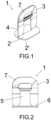
- a first preferred embodiment of the invention can be seen in the indicated Figures 1 to 3 , wherein the thickening of the levelling piece (1) has a gradual increase in thickness extending in the radial direction (7) in the upper middle region of the inverted U-shaped element (3).
- the thickening in this first preferred embodiment of the invention is defined by a perimeter of variable thickness in the upper middle region of the inverted U-shaped element (3).
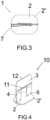
- Figures 4 and 5 depict the second preferred embodiment of the invention, wherein the thickening of the levelling piece (10) is defined by a projection (11) extending from one side to the opposite side of the inverted U-shaped element (3), generating a thickening in a plane parallel to the base (2).
- the thickness of the inverted U-shaped element decreases gradually as it approaches the end opposite the base (2), in this sense
- Figure 5 shows the thickness (e11) of the projection (11) which decreases until defining a pointed termination (12) having a smaller thickness (e12) than the thickness (e11) of the projection (11).
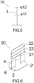
- the thickening is defined by a projection (21) as can be seen in Figures 6 and 7 .
- Said projection (21) extends from one side to the opposite side of the inverted U-shaped element (3) and generates a thickening in a plane parallel to the base (2).
- the thickness of the thickening in the third preferred embodiment decreases by way of steps (23) as it approaches the end opposite the base (2), defining a pointed termination (22).
- the thickness (e21) of the projection (21) is greater than the thickness (e23) of the step (23), whereas the thickness (e23) of the step (23) is greater than the thickness (e22) of the pointed termination (22).
- Figure 6 depicts a step (23) located between the projection (21) and the pointed termination (22), however, said embodiment is not limiting of the present protection.
- the levelling piece can have more than one step (23) in order to decrease the thickness of the thickening.
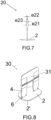
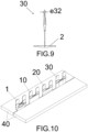
- the fourth preferred embodiment of the invention depicted in Figures 8 and 9 allows observing that the levelling piece (30) has a thickening defined by a projection (31) arranged centred in the upper middle region of the inverted U-shaped element (3).
- the thickness of the projection (31) decreases gradually as it approaches the end opposite the base (2), defining a pointed termination (32) of thickness (e32), as depicted in Figure 9 .
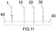
- any of the proposed levelling pieces (1), (10), (20), (30) has a configuration such that they enable subsequent use for placement between the cladding panels (40), performing a spacing or separating function.
- it is a significant use which involves reusing that portion of the levelling piece which, up until now, was unusable once levelling between the cladding panels (40) had been performed.
Landscapes
- Engineering & Computer Science (AREA)
- Architecture (AREA)
- Civil Engineering (AREA)
- Structural Engineering (AREA)
- On-Site Construction Work That Accompanies The Preparation And Application Of Concrete (AREA)
- Finishing Walls (AREA)
- Road Paving Structures (AREA)
Abstract
The present invention relates to a levelling piece for cladding panels that has an inverted T-shaped profile, provided with a flat base from which an inverted U-shaped element emerges perpendicularly, joined by respective arms defining an opening, the upper middle region of the inverted U-shaped element having a thickening of variable thickness that decreases gradually defining a pointed termination. The configuration of the levelling piece allows up to four preferred embodiments of the invention to be implemented, with the advantage that they all include variable-thickness thickening in the upper middle region of the inverted U-shaped element in order to serve as a spacing wedge for use once it has been separated from the base after the levelling of the cladding panels and the drying of the bonding material.
Description
- The present invention relates to a levelling piece for cladding panels, such as wall tiles, floor tiles, or paving tiles, intended for facilitating the installation of constructive elements of this type. The levelling piece has an inverted T-shaped profile configuration with a flat base from which an inverted U-shaped element which has a thickening of variable thickness emerges perpendicularly.
- The object of the invention is to provide use in addition to that commonly envisaged for the levelling piece. In this sense, instead of being disposed of after levelling the panels, the inverted U-shaped element, which is part of the levelling piece, is used for a second use as a result of its novel configuration.
- Levelling pieces which, when used in combination with a wedge, facilitate the placement of cladding panels and their uniform arrangement on floors, walls, or other surfaces, are known in the state of the art. To that end, there is provided a bonding material, such as mortar or an adhesive, on which the panels which will clad the surface are placed. Said operation involves as many levelling pieces as necessary for the perfect separation and levelling of the cladding panels.
- As shown in patent document number
ES2598702T3 - Cladding panels are then arranged such that there are at least two levelling pieces on each side.
- The wedge is introduced through the opening of each levelling piece which separates two cladding panels. Upon hitting the wedge, a force is generated on the inverted U-shaped element tending to separate the levelling piece and the surface to be clad, which will also cause the separation of the cladding panels, with the panels being levelled out.
- When the bonding material is dry, an impact is applied on the inverted U-shaped element which causes the breakage and separation thereof with respect to the base, with said inverted U-shaped element being disposable and the base being buried under the cladding panels and concealed when grout is applied to seal the joints.
- The described operation requires the use and breakage of a large number of levelling pieces which causes the removal of a large amount of polymer material to be disposed of without any additional application envisaged for same. Therefore, the applicant of the present utility model detects the need to provide an invention which offers an environmentally friendly solution which involves reusing the inverted U-shaped element after its separation from the levelling piece.
- The configuration of the proposed levelling piece enables a second function of that part which is unusable once the levelling of cladding panels has been performed and the bonding material is dry, specifically a wedge-like separating function.
- In this sense, the levelling piece for cladding panels has an inverted T-shaped profile with a flat base from which an inverted U-shaped element of the known types emerges perpendicularly. The inverted U-shaped element is joined to the base by respective arms defining an opening.
- The arms optionally have notches at the ends which are joined to the base. These notches are what allow the arms of the inverted U-shaped element to break once the cladding panels have been properly installed and levelled as a result of the levelling piece.
- The levelling piece has in the upper middle region of the inverted U-shaped element a thickening of variable thickness. It is precisely said thickening of variable thickness that generates a separating or spacing function in any of the preferred embodiments of the invention that are described in detail below.
- In this sense, said thickening of variable thickness is defined by a perimeter of variable thickness in the upper middle region of the inverted U-shaped element or by a projection extending from one side to the opposite side of the inverted U-shaped element, generating a thickening in a plane parallel to the base the thickness of which decreases gradually as it approaches the end opposite the base, defining a pointed termination.
- In any case, the thickening in a perimeter of variable thickness or at a pointed termination defines a spacing wedge shape which allows the introduction thereof between the cladding panels to keep them separated during installation.
- In this sense, once the inverted U-shaped element is separated from of the rest of the levelling piece, it can be used as a spacing wedge for other elements for cladding installation. In other words, part of the levelling piece is utilized for another function, in contrast to the known levelling pieces in which the inverted U-shaped element is disposed of once separated from the rest of the levelling piece, with the subsequent material wastage and environmental impact.
- Based on the foregoing, the use of the inverted U-shaped element, which includes the mentioned thickening of variable thickness, offers a versatile and environmentally friendly levelling piece.
- To complete the description that will be made below and in order to help to better understand the features of the invention according to a preferred practical embodiment thereof, a set of drawings is attached as an integral part of said description in which the following is depicted in an illustrative and non-limiting manner:
-
Figure 1 shows a perspective view of the levelling piece for cladding panels according to a first preferred embodiment object of the invention. -
Figure 2 shows a front view of the levelling piece according to the first preferred embodiment of the invention depicted in the preceding figure. -
Figure 3 shows a top view of the levelling piece according to the first preferred embodiment depicted in the preceding figures. -
Figure 4 shows a perspective view of the levelling piece for cladding panels according to a second preferred embodiment object of the invention. -
Figure 5 shows a sectional view of the levelling piece according to the second preferred embodiment depicted inFigure 4 . -
Figure 6 shows a perspective view of the levelling piece for cladding panels according to a third preferred embodiment object of the invention. -
Figure 7 shows a sectional view of the levelling piece according to the third preferred embodiment depicted inFigure 6 . -
Figure 8 shows a perspective view of the levelling piece for cladding panels according to a fourth preferred embodiment object of the invention. -
Figure 9 shows a sectional view of the levelling piece according to the fourth preferred embodiment depicted inFigure 8 . -
Figure 10 shows a perspective view of the preferred embodiments of the levelling piece used according to the second use as a spacing wedge proposed in the present invention. -
Figure 11 shows a sectional view of the preferred embodiments of the levelling piece depicted between cladding panels according to the second use as a spacing wedge depicted inFigure 10 . - In any of the preferred embodiments of the invention, the levelling piece has an inverted T-shaped profile with a flat base (2) from which an inverted U-shaped element (3) emerges perpendicularly, and wherein the inverted U-shaped element (3) is joined to the base (2) by respective arms (4) defining an opening (5). Likewise, the levelling pieces of the present invention have in the preferred embodiment thereof notches (6) arranged at the ends of the arms (4) which are joined to the base (2), in order to facilitate the weakening and breakage of the inverted U-shaped element with respect to the base (2).
- As can be seen in the figures of any preferred embodiment of the levelling piece of the invention, the ends of the base (2) farthest away from the inverted U-shaped element (3) preferably have a reduction in thickness and/or bevelled corners (2') in the base (2), included for the purpose of minimising the amount of material used per levelling piece manufactured, always maintaining the mechanical strength necessary for performing its function.
- Notwithstanding the foregoing, this section illustrates up to four preferred embodiments of the invention having in the upper middle region of the inverted U-shaped element (3) a thickening of variable thickness in order to serve as a spacing wedge for use once it has been separated from the base (2) after the levelling of the cladding panels and the drying of the bonding material.
- In this sense, a first preferred embodiment of the invention can be seen in the indicated
Figures 1 to 3 , wherein the thickening of the levelling piece (1) has a gradual increase in thickness extending in the radial direction (7) in the upper middle region of the inverted U-shaped element (3). In this way, the thickening in this first preferred embodiment of the invention is defined by a perimeter of variable thickness in the upper middle region of the inverted U-shaped element (3). - Moreover,
Figures 4 and5 depict the second preferred embodiment of the invention, wherein the thickening of the levelling piece (10) is defined by a projection (11) extending from one side to the opposite side of the inverted U-shaped element (3), generating a thickening in a plane parallel to the base (2). - To generate the spacing wedge in the second preferred embodiment of the invention, the thickness of the inverted U-shaped element decreases gradually as it approaches the end opposite the base (2), in this sense
Figure 5 shows the thickness (e11) of the projection (11) which decreases until defining a pointed termination (12) having a smaller thickness (e12) than the thickness (e11) of the projection (11). - In a third preferred embodiment of the levelling piece (20), the thickening is defined by a projection (21) as can be seen in
Figures 6 and7 . Said projection (21) extends from one side to the opposite side of the inverted U-shaped element (3) and generates a thickening in a plane parallel to the base (2). - Unlike what has been described in detail for the second preferred embodiment, the thickness of the thickening in the third preferred embodiment decreases by way of steps (23) as it approaches the end opposite the base (2), defining a pointed termination (22). As can be seen in
Figure 7 , the thickness (e21) of the projection (21) is greater than the thickness (e23) of the step (23), whereas the thickness (e23) of the step (23) is greater than the thickness (e22) of the pointed termination (22). -
Figure 6 depicts a step (23) located between the projection (21) and the pointed termination (22), however, said embodiment is not limiting of the present protection. - In this sense, the levelling piece can have more than one step (23) in order to decrease the thickness of the thickening.
- Moreover, the fourth preferred embodiment of the invention depicted in
Figures 8 and9 allows observing that the levelling piece (30) has a thickening defined by a projection (31) arranged centred in the upper middle region of the inverted U-shaped element (3). The thickness of the projection (31) decreases gradually as it approaches the end opposite the base (2), defining a pointed termination (32) of thickness (e32), as depicted inFigure 9 . - As can be seen in
Figures 10 and11 , any of the proposed levelling pieces (1), (10), (20), (30) has a configuration such that they enable subsequent use for placement between the cladding panels (40), performing a spacing or separating function. Advantageously, it is a significant use which involves reusing that portion of the levelling piece which, up until now, was unusable once levelling between the cladding panels (40) had been performed.
Claims (8)
- A levelling piece for cladding panels that has an inverted T-shaped profile with a flat base (2) from which an inverted U-shaped element (3) emerges perpendicularly, characterized in that the inverted U-shaped element (3) is joined to the base (2) by respective arms (4) defining an opening (5), the upper middle region of the inverted U-shaped element having a thickening of variable thickness that decreases gradually defining a pointed termination.
- The levelling piece (1) according to claim 1, characterized in that the thickening has a gradual increase in thickness extending in the radial direction (7) in the upper middle region of the inverted U-shaped element (3), defining a perimeter of variable thickness in the upper middle region of the inverted U-shaped element (3).
- The levelling piece (10) according to claim 1, characterized in that the thickening is defined by a projection (11) extending from one side to the opposite side of the inverted U-shaped element (3), generating a thickening in a plane parallel to the base (2) the thickness of which decreases gradually as it approaches the end opposite the base (2), defining a pointed termination (12).
- The levelling piece (20) according to claim 1, characterized in that the thickening is defined by a projection (21) extending from one side to the opposite side of the inverted U-shaped element (3), generating a thickening in a plane parallel to the base (2) the thickness of which decreases by way of steps (23) as it approaches the end opposite the base (2), defining a pointed termination (22).
- The levelling piece (30) according to claim 1, characterized in that the thickening is defined by a projection (31) arranged centred in the upper middle region of the inverted U-shaped element (3), wherein the thickness of the projection (31) decreases gradually as it approaches the end opposite the base (2), defining a pointed termination (32).
- The levelling piece according to any of the preceding claims, characterized in that the arms (4) have notches (6) at the ends which are joined to the base (2).
- The levelling piece according to any of the preceding claims, characterized in that the ends of the base (2) farthest away from the inverted U-shaped element (3) have a reduction in thickness.
- The levelling piece according to any of the preceding claims, characterized in that the base (2) has bevelled corners (2').
Applications Claiming Priority (2)
| Application Number | Priority Date | Filing Date | Title |
|---|---|---|---|
| ES202131155U ES1272199Y1 (en) | 2021-06-03 | 2021-06-03 | leveling piece |
| PCT/ES2022/070343 WO2022254072A1 (en) | 2021-06-03 | 2022-06-02 | Levelling piece |
Publications (1)
| Publication Number | Publication Date |
|---|---|
| EP4350102A1 true EP4350102A1 (en) | 2024-04-10 |
Family
ID=76578264
Family Applications (1)
| Application Number | Title | Priority Date | Filing Date |
|---|---|---|---|
| EP22815421.7A Pending EP4350102A1 (en) | 2021-06-03 | 2022-06-02 | Levelling piece |
Country Status (4)
| Country | Link |
|---|---|
| EP (1) | EP4350102A1 (en) |
| CA (1) | CA3221013A1 (en) |
| ES (1) | ES1272199Y1 (en) |
| WO (1) | WO2022254072A1 (en) |
Family Cites Families (4)
| Publication number | Priority date | Publication date | Assignee | Title |
|---|---|---|---|---|
| US20120297714A1 (en) * | 2011-05-27 | 2012-11-29 | Tavy Enterprises, Llc | Wege-Shaped Tile Spacer |
| ES1075226Y (en) | 2011-06-10 | 2011-11-18 | Serrano Luis Miguel Perales | DEVICE FOR LEVELING RIGID COATING PLATES |
| ES1214135Y (en) * | 2018-05-14 | 2018-09-13 | Haro Garcia Antonio Luis | PART OF LEVEL OF COATING PLATES |
| BR102019006025A2 (en) * | 2019-03-27 | 2020-10-13 | Jefferson Prestes De Andrade | KIT FOR SPACING AND LEVELING COATING PARTS |
-
2021
- 2021-06-03 ES ES202131155U patent/ES1272199Y1/en active Active
-
2022
- 2022-06-02 EP EP22815421.7A patent/EP4350102A1/en active Pending
- 2022-06-02 WO PCT/ES2022/070343 patent/WO2022254072A1/en active Application Filing
- 2022-06-02 CA CA3221013A patent/CA3221013A1/en active Pending
Also Published As
| Publication number | Publication date |
|---|---|
| WO2022254072A1 (en) | 2022-12-08 |
| ES1272199Y1 (en) | 2022-03-17 |
| ES1272199U (en) | 2021-07-01 |
| CA3221013A1 (en) | 2022-12-08 |
Similar Documents
| Publication | Publication Date | Title |
|---|---|---|
| US10724254B1 (en) | Wedge leveling system | |
| US10934723B2 (en) | Tile laying accessory | |
| EP2573296B1 (en) | Leveling spacer for laying wall tiles, paving tiles and the like with the interposition of gaps | |
| US20180291640A1 (en) | Tile-levelling spacer device | |
| US20200063448A1 (en) | Tile positioning device | |
| EP3695073B1 (en) | Tile spacer | |
| EP2966239B1 (en) | A spacer element for covering elements | |
| EP3569793B1 (en) | Levelling part for cladding tiles | |
| US20200318364A1 (en) | Integrally fabricated tile-leveling base and wedge | |
| EP4350102A1 (en) | Levelling piece | |
| KR20150024458A (en) | Connections | |
| AU2018202023A1 (en) | Cast-in-place anchors | |
| ITRM20130722A1 (en) | ANTI-SOURCE CONNECTOR ACCORDING TO THE PREVALENT STRESS TO TRACTION AND COMPRESSION | |
| US1725200A (en) | Wall tie | |
| US1859779A (en) | Wall board fastener | |
| KR102204998B1 (en) | Dry Construction System of Thin Bricks | |
| EP2341198A2 (en) | Modular inlet sleeve | |
| JP6945911B1 (en) | How to build openwork brick wall lumber | |
| EP4350101A1 (en) | Levelling piece | |
| JP5716486B2 (en) | Girder bridge main girder, girder bridge main girder and concrete floor slab joint structure, concrete floor slab, girder bridge and bridge | |
| EP4166734A1 (en) | Device for levelling flat cladding parts on vertical or horizontal surfaces | |
| EP3964645A1 (en) | Interlocking paving brick assembly | |
| CN109537802B (en) | Superposed beam structure | |
| US20100006722A1 (en) | Brace for retaining panels during cement distribution | |
| SE439045B (en) | PROCEDURE OF ANCHORING A VEIL BOLT IN ONE HALL AND A VILBULT DEVICE |
Legal Events
| Date | Code | Title | Description |
|---|---|---|---|
| STAA | Information on the status of an ep patent application or granted ep patent |
Free format text: STATUS: THE INTERNATIONAL PUBLICATION HAS BEEN MADE |
|
| PUAI | Public reference made under article 153(3) epc to a published international application that has entered the european phase |
Free format text: ORIGINAL CODE: 0009012 |
|
| STAA | Information on the status of an ep patent application or granted ep patent |
Free format text: STATUS: REQUEST FOR EXAMINATION WAS MADE |
|
| 17P | Request for examination filed |
Effective date: 20231227 |
|
| AK | Designated contracting states |
Kind code of ref document: A1 Designated state(s): AL AT BE BG CH CY CZ DE DK EE ES FI FR GB GR HR HU IE IS IT LI LT LU LV MC MK MT NL NO PL PT RO RS SE SI SK SM TR |