EP4350077B1 - Engin de génie civil et procédé de fonctionnement d'un engin de génie civil - Google Patents
Engin de génie civil et procédé de fonctionnement d'un engin de génie civil Download PDFInfo
- Publication number
- EP4350077B1 EP4350077B1 EP22199993.1A EP22199993A EP4350077B1 EP 4350077 B1 EP4350077 B1 EP 4350077B1 EP 22199993 A EP22199993 A EP 22199993A EP 4350077 B1 EP4350077 B1 EP 4350077B1
- Authority
- EP
- European Patent Office
- Prior art keywords
- civil engineering
- display
- machine
- control unit
- data
- Prior art date
- Legal status (The legal status is an assumption and is not a legal conclusion. Google has not performed a legal analysis and makes no representation as to the accuracy of the status listed.)
- Active
Links
Images

Classifications
-
- E—FIXED CONSTRUCTIONS
- E02—HYDRAULIC ENGINEERING; FOUNDATIONS; SOIL SHIFTING
- E02D—FOUNDATIONS; EXCAVATIONS; EMBANKMENTS; UNDERGROUND OR UNDERWATER STRUCTURES
- E02D7/00—Methods or apparatus for placing sheet pile bulkheads, piles, mouldpipes, or other moulds
-
- E—FIXED CONSTRUCTIONS
- E02—HYDRAULIC ENGINEERING; FOUNDATIONS; SOIL SHIFTING
- E02D—FOUNDATIONS; EXCAVATIONS; EMBANKMENTS; UNDERGROUND OR UNDERWATER STRUCTURES
- E02D13/00—Accessories for placing or removing piles or bulkheads, e.g. noise attenuating chambers
- E02D13/06—Accessories for placing or removing piles or bulkheads, e.g. noise attenuating chambers for observation while placing
-
- E—FIXED CONSTRUCTIONS
- E02—HYDRAULIC ENGINEERING; FOUNDATIONS; SOIL SHIFTING
- E02D—FOUNDATIONS; EXCAVATIONS; EMBANKMENTS; UNDERGROUND OR UNDERWATER STRUCTURES
- E02D17/00—Excavations; Bordering of excavations; Making embankments
- E02D17/13—Foundation slots or slits; Implements for making these slots or slits
-
- E—FIXED CONSTRUCTIONS
- E02—HYDRAULIC ENGINEERING; FOUNDATIONS; SOIL SHIFTING
- E02F—DREDGING; SOIL-SHIFTING
- E02F9/00—Component parts of dredgers or soil-shifting machines, not restricted to one of the kinds covered by groups E02F3/00 - E02F7/00
- E02F9/26—Indicating devices
- E02F9/261—Surveying the work-site to be treated
-
- E—FIXED CONSTRUCTIONS
- E02—HYDRAULIC ENGINEERING; FOUNDATIONS; SOIL SHIFTING
- E02F—DREDGING; SOIL-SHIFTING
- E02F9/00—Component parts of dredgers or soil-shifting machines, not restricted to one of the kinds covered by groups E02F3/00 - E02F7/00
- E02F9/26—Indicating devices
- E02F9/264—Sensors and their calibration for indicating the position of the work tool
-
- E—FIXED CONSTRUCTIONS
- E02—HYDRAULIC ENGINEERING; FOUNDATIONS; SOIL SHIFTING
- E02F—DREDGING; SOIL-SHIFTING
- E02F9/00—Component parts of dredgers or soil-shifting machines, not restricted to one of the kinds covered by groups E02F3/00 - E02F7/00
- E02F9/26—Indicating devices
- E02F9/267—Diagnosing or detecting failure of vehicles
-
- E—FIXED CONSTRUCTIONS
- E21—EARTH OR ROCK DRILLING; MINING
- E21B—EARTH OR ROCK DRILLING; OBTAINING OIL, GAS, WATER, SOLUBLE OR MELTABLE MATERIALS OR A SLURRY OF MINERALS FROM WELLS
- E21B7/00—Special methods or apparatus for drilling
- E21B7/02—Drilling rigs characterised by means for land transport with their own drive, e.g. skid mounting or wheel mounting
- E21B7/022—Control of the drilling operation; Hydraulic or pneumatic means for activation or operation
Definitions
- the invention relates to a civil engineering machine, in particular a drilling rig, with a mobile carrier device, a mast or boom arm which is arranged on the carrier device, and a civil engineering tool which is adjustably arranged on the mast or boom arm for carrying out a civil engineering measure.
- the civil engineering machine also has a control unit and an operating cabin for at least one operator with at least one display device, in particular a monitor, which is connected to the control unit and is designed to display operating data recorded by the control unit to a machine operator in several display fields on the at least one display device.
- the invention also relates to a method for operating a civil engineering machine.
- the civil engineering machine can be, for example, a diaphragm wall cutter, a pile driver, a cable excavator, a grab excavator, but also a mobile crane or a mobile boom crane.
- a foundation element can be formed, for example, by creating a hole in the ground, such as a borehole or a milling slot, with the hole then being filled with a hardenable medium, in particular a mortar, to form a foundation pile or a diaphragm wall segment, if necessary with additional reinforcement.
- a foundation element can also be created by ramming or vibrating, such as a foundation pile or a plank.
- a foundation element is not limited to a load-bearing or load-bearing function, but can alternatively or additionally also take on a sealing function and/or other tasks, as is known, for example, from special foundation engineering when enclosing excavation pits with sealing walls.
- Such civil engineering machines are known, for example, from EP 3299523 A1 , the EP 3296467 A1 or the JP 2022-077258 A known.
- Display devices in civil engineering machines are used to show the machine operator operating data that is recorded by the control unit from internal and/or external sensors so that he can control the civil engineering machine effectively and safely.
- the data can be, for example, the current depth of the civil engineering tool, the torque of a winch or the temperature of the oil in an oil circuit.
- the invention is therefore based on the object of specifying a civil engineering machine and a method for operating a civil engineering machine, which facilitates the use of a civil engineering machine by different machine operators.
- control unit is designed in such a way that a display, an arrangement and/or a type of display fields can be changed and set by a machine operator, and can be stored in a data memory as a personal configuration of the machine operator independently of the control unit.
- independent of the control unit also means that the configuration can be stored independently of the civil engineering machine in which the control unit is provided.
- a basic idea of the invention is to allow the machine operator to arrange and configure the displays on the display device in a user-specific manner. This means that an experienced machine operator who carries out complicated tasks can have certain information relevant to his work displayed, whereas a less experienced machine operator can put together the display device and the information shown there in such a way that it also shows the appropriate data for him, including other data.
- the invention makes it possible to adapt the display device to the respective machine operator, but also to the respective work order. So that this adaptation is not lost, it can be stored according to the invention.
- the invention provides that the information required for the user-specific display is not necessarily stored on the civil engineering machine or in the control unit, but independently of it.
- control unit has a transmission device, in particular a data transmission device, with which data for the personal configuration of the display fields can be transmitted to a data storage device outside the control unit.
- a transmission device in particular a data transmission device, with which data for the personal configuration of the display fields can be transmitted to a data storage device outside the control unit.
- the information for the user-specific configuration is not stored in the control unit itself and not necessarily in the civil engineering machine by means of the transmission device. This makes it possible to access the relevant information centrally.
- the transmission device is designed to store the data relating to the personal configuration on a mobile data carrier, a mobile computer unit, a central data depository and/or in a Cloud storage. This is done in order to save the corresponding data there.
- the elements in the above list can be seen as alternative ways in which the data for the personal configuration can be saved.
- a mobile data carrier can be understood as, for example, a machine key, a USB stick or another data storage device that can be written to wirelessly, for example via Bluetooth, RFID or NFC technologies.
- a mobile computer unit can be seen as, for example, a laptop, a tablet computer or a smartphone.
- the display device can be designed in any way. This can be a monitor, for example, but also other types of display devices, such as data glasses, a head-up display or a tablet.
- the display device is preferably designed to show numbers, functions, graphics, animations and/or photo and video images.
- any information can be displayed in a suitable manner on the display device. It is also possible for the machine operator to define the type of display of certain data himself. For example, the temperature of the engine oil of the civil engineering machine can be displayed as a number, but also as a bar chart and/or in the form of a circular display instrument. The machine operator can set the exact design according to what is easiest for him to read.
- a pre-selection of retrievable operating data, possible display types and/or arrangement options is stored in the control unit and/or can be retrieved from it and can be retrieved and selected by the machine operator to create the personal configuration.
- a type of A toolbox can be provided from which the individual machine operator can put together the display and the type of display that is best for him in his experience in the respective work situation. Templates can also be provided here. This makes such a setting easier for less experienced machine operators in particular.
- operating data can be understood as information on current and past operating/machine states, for example, but also information on production data such as details on foundation elements to be created or soil information.
- the control unit has a display configuration mode, wherein when the display configuration mode is activated, the display on the at least one display device can be changed and saved.
- the display configuration mode can be used to influence, for example, the position or type of a specific display on the display device.
- the display device consists of several monitors, for example, so that some displays are displayed on the first monitor while other displays are displayed on the second monitor.
- different types of display devices can also be combined, for example a fixed monitor and a tablet PC, which can also be removed from the operator's cabin.
- the size, type, position and/or color of the display field is adjustable.
- the graphical representation of the information can also be adjustable, so that some information is displayed as digits or numbers, others as graphics, such as bars.
- a particularly simple setting is achieved if the at least one display device is designed as a touchscreen on which the display fields can be changed and/or adjusted directly by touching the display device. In this way, an intuitive setting of the individual display fields can be achieved particularly easily.
- a setting via a mouse or a touchpad can also be made via a web interface or a mobile phone app.
- an identification device is arranged by means of which a machine operator who wishes to operate the civil engineering machine can be identified.
- the control unit can be designed to automatically and/or on request call up a personal configuration of the identified machine operator in order to bring about a desired display on the at least one display device.
- the call can be made from an internal memory in the control unit or the civil engineering machine, but also from an external memory that is made available via an interface. This can also be, for example, a central data storage device that is provided on servers of the manufacturer of the construction machine or the operating company.
- an identification device it is particularly easy to assign the corresponding user-specific setting of the display device to a user and make it available.
- a user name optionally in conjunction with a password, a fingerprint sensor or a correspondingly coded key for the civil engineering machine can be used as an identification device.
- the invention is particularly advantageous when used in conjunction with an arrangement that includes several civil engineering machines that can be selected by a machine operator.
- the advantages of the invention then arise in a particular way, since it is not necessary to ensure that a machine operator uses the same civil engineering machine each time. It is therefore possible for a machine operator to use different civil engineering machines and actively transfer his desired configuration to the civil engineering machine or to call it up there, so that he has his usual display available on the display device.
- a central data storage location can be understood as, for example, a database that can be queried via the Internet. It is not necessary that there is just one database; several databases can also be available that can be used alternatively to one another or act as a backup for one another.
- the invention further relates to a method for operating a civil engineering machine as described above or an arrangement of this type. It is provided that at least one machine operator creates a personal configuration for the display fields on the at least one display device and stores it in a data storage device. It is also provided that, upon request and/or through automatic identification of the machine operator, the control unit retrieves the personal configuration of the machine operator from the data storage device and a corresponding display is effected in accordance with the personal configuration on the at least one display device.
- a machine operator can also be regarded as an administrator or master user who defines individual personal configurations for different machine operators.
- the settings of the different machine operators can also be copied, so that different display fields or different contents are shown on the at least one display device for an experienced group of machine operators than for inexperienced machine operators.
- the same also applies to different operating modes of the civil engineering machine. For example, with a trench wall cutter that cuts into hard rock, different data on the display fields are of interest to the machine operator than with a trench wall cutter that creates a trench wall in sandy subsoil.
- the data storage can be located in the civil engineering machine or remote from it.
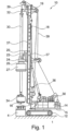
- a civil engineering machine 10 according to the invention which can be used as a drilling device according to Fig. 1 is designed, has an undercarriage 12, preferably designed as a crawler chassis, and an upper carriage 14 rotatably mounted thereon.
- the undercarriage 12 and the upper carriage 14 form a carrier device 15.
- the drive units and the control station for a machine operator of the civil engineering machine 10 can be arranged on the upper carriage 14 in a known manner.
- a control unit 40 and a display device 50, in particular a monitor, can be arranged in the control station.
- a substantially vertical mast 18 with an upper mast head 19 can be adjustably attached to a front side of the superstructure 14 via an articulation kinematics 16 with neck cylinders.
- a carriage 20 can be guided displaceably along a front side of the mast 18.
- a first drilling drive 22 can be provided on the carriage 20, which can have a hydraulic motor 24.
- a second drive 26 with a sleeve-shaped rotary connection 27 for establishing a rotationally fixed connection to a support tube 4 can be provided on the carriage 20.
- the second drive 26 can, for example, essentially consist of a gear connection to the first drilling drive 22 with the hydraulic motor 24 in order to apply a torque to the rotary connection 27 and thus the support tube 4.
- the approximately sleeve-shaped first drilling drive 22 can, for example, be penetrated by a drill rod 30, which can be designed as a Kelly rod with external drive strips.
- the drill rod 30 can have an upper suspension 32, with which the drill rod 30 is connected to a main cable 39.
- the main cable 39 can be guided via deflection rollers on the mast head 19 to a main winch 38 on the top of the upper carriage 14.
- the drill rod 30 can be moved vertically by operating the main winch 38.
- the carriage 20 can be connected to a feed cable 37, which can be guided above and below the carriage 20 along the mast 18 and can be operated by a feed winch 36.
- the carriage 20 can be moved up or down along a guide of the mast 18 by the feed winch 36.
- a drilling tool is attached to the underside of the drill rod 30 as a civil engineering tool 34 for removing soil material.
- the civil engineering tool 34 is in the illustrated embodiment according to Fig. 1 designed as a drilling bucket.
- the diameter of the drilling tool is designed such that it can be inserted into the inner cavity of the support tube 4.
- the civil engineering machine 10 can be used to create a cased borehole in the ground 1.
- a hardenable mass can be introduced into the borehole, which then hardens to form the foundation element.
- the support pipe 4 can remain in the borehole as part of the foundation element or can preferably be pulled out of the ground 1 before hardening.
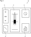
- a schematic example of a display device 50 is shown. This shows five display fields 51 as an example, each of which shows different information.
- the middle display field 51 for example, shows the current depth of a borehole and the drilling depth to be achieved in graphical form.
- a display field 51 is shown, which has a round element that shows, for example, the current torque of the motor.
- a display field 51 with a bar graph is shown. This can, for example, show the current transmission oil pressure in a clear manner.
- a numerical display is shown in the upper area on the left side of the display device 50.
- a display field 51 is shown, which shows a progression curve, for example the depth of the borehole over time.
- the various display fields 51 in any way on the display device 50.
- Different display fields 51 can also be added and configured using corresponding functions.
- the type of display can also be selected. This also applies for example for the selection of the information displayed, the position, the level of detail or the like.
- the display device 50 can thus be specially configured for the respective machine user so that the data required for his current task is displayed in a particularly advantageous manner. Personal preferences can also be taken into account in this way.
- not only one display device 50 can be used, but also several, which can be arranged one above the other or next to one another, for example. This also makes it possible to move a display field 51 from a main display device to a secondary display device if the information in the display field 51 is rarely used.
- Fig. 3 a schematic view is shown which shows an exemplary basic structure of the data flow of a civil engineering machine 10 according to the invention with respect to the display devices 50.
- a central element here is the control unit 40.
- the sensor devices 48 can be, for example, torque sensors or temperature sensors. These do not necessarily have to be arranged on the civil engineering machine according to the invention, but can also be external sensors.
- the transmission to the control unit 40 can be either wired or wireless. Other sources of information can also be used by the control unit 40, for example project or construction plans. In general, the sensor devices 48 can even be viewed as a data source.
- These data and information are output via the control unit 40 to, in this case, two display devices 50.
- the data are shown in display fields 51, as previously described with respect to Fig. 2
- the machine user can select which data and information should be displayed and in what manner.
- a transmission device 60 can also be transferred to an external memory 44.
- the external memory 44 can be, for example, a data storage device, but also a storage location in a cloud, a server or the like.
- the relevant design of the transmission device 60 can therefore be intended for a wired transfer, but also for a wireless transfer.
- the transmission device 60 can be designed in a simple manner in the form of a modem, which transmits the data to a server via a mobile network.
- a machine operator starts a civil engineering machine 10
- he can load his configuration either from the internal memory 42 or from the external memory 44 via the transmission device 60, so that the display fields 51 are shown on the display devices 50 in the manner that is most clear for him.
- the arrangement of the display fields 51 on the display device 50 can preferably be done via a touchscreen if the display device 50 is designed in this way.
- the control can also be done by means of a rotary element, a slider or other human-machine communication devices.
- An identification device can also be provided which can correspond to the control unit, by means of which it can be recognized which machine operator is operating the civil engineering machine 10, whereby based on this information his individual configuration of the display devices 50 is loaded. This can be implemented both locally from the internal memory 42 and via an external memory 44 which can be accessed accordingly.
- the external memory 44 can also be used by different civil engineering machines 10 simultaneously, so that data transfer of the configuration from one civil engineering machine 10 to another is possible.
Landscapes
- Engineering & Computer Science (AREA)
- Mining & Mineral Resources (AREA)
- Civil Engineering (AREA)
- Structural Engineering (AREA)
- General Engineering & Computer Science (AREA)
- Life Sciences & Earth Sciences (AREA)
- General Life Sciences & Earth Sciences (AREA)
- Paleontology (AREA)
- Geology (AREA)
- Fluid Mechanics (AREA)
- Geochemistry & Mineralogy (AREA)
- Physics & Mathematics (AREA)
- Environmental & Geological Engineering (AREA)
- Component Parts Of Construction Machinery (AREA)
- Placing Or Removing Of Piles Or Sheet Piles, Or Accessories Thereof (AREA)
- Earth Drilling (AREA)
Claims (11)
- Engin de génie civil (10), en particulier engin de forage, comprenant- un appareil porteur mobile (15),- un mât (18) ou un bras disposé sur l'appareil porteur (15),- un outil de génie civil (34) disposé de manière réglable sur le mât (18) ou le bras pour effectuer une opération de génie civil,- une unité de commande (40), et- une cabine de commande pour au moins un opérateur, comprenant au moins un dispositif d'affichage (50), en particulier un écran, qui est en liaison avec l'unité de commande (40) et qui est conçu pour afficher à l'opérateur de l'engin des données de fonctionnement, saisies par l'unité de commande (40), dans plusieurs champs d'affichage (51) sur ledit au moins un dispositif d'affichage (50),caractérisé en ce quel'unité de commande (40) est conçue de telle sorte que l'affichage, la disposition et/ou le type des champs d'affichage (51) peuvent être modifiés et réglés par un opérateur de l'engin et peuvent être mémorisés dans une mémoire de données en tant que configuration personnelle de l'opérateur de l'engin, indépendamment de l'unité de commande (40), eten ce que la taille, le type, la position et/ou la couleur d'un champ d'affichage sont réglables.
- Engin de génie civil (10) selon la revendication 1,
caractérisé en ce que
l'unité de commande (40) comprend un dispositif de transmission (60) permettant de transmettre des données relatives à la configuration personnelle des champs d'affichage (51) dans la mémoire de données à l'extérieur de l'unité de commande (40). - Engin de génie civil (10) selon la revendication 2,
caractérisé en ce que
le dispositif de transmission (60) est conçu pour transmettre les données relatives à la configuration personnelle à un support de données mobile, tel qu'une clé de l'engin, une unité informatique mobile, un ordinateur portable, une tablette ou un smartphone, à un service central de stockage de données et/ou vers une mémoire en nuage. - Engin de génie civil selon l'une des revendications 1 à 3,
caractérisé en ce que
au moins un dispositif d'affichage (50) est conçu pour afficher des chiffres, des fonctions, des graphiques, des animations et/ou des images photo/vidéo. - Engin de génie civil (10) selon l'une des revendications 1 à 4,
caractérisé en ce que
une présélection de données de fonctionnement à appeler, de types d'affichage possibles et/ou de possibilités d'agencement est mémorisée dans l'unité de commande (40) et/ou peut être appelée par celle-ci et peut être appelée et sélectionnée par l'opérateur de l'engin pour créer la configuration personnelle. - Engin de génie civil (10) selon l'une des revendications 1 à 5,
caractérisé en ce que
l'unité de commande (40) comprend un mode de configuration d'affichage, l'affichage sur ledit au moins un dispositif d'affichage (50) pouvant être modifié et mémorisé lors de l'activation du mode de configuration d'affichage. - Engin de génie civil (10) selon l'une des revendications 1 à 6,
caractérisé en ce que
au moins un dispositif d'affichage (50) est conçu comme un écran tactile permettant de modifier et/ou de régler les champs d'affichage (51) directement en touchant le dispositif d'affichage (50). - Engin de génie civil (10) selon l'une des revendications 1 à 7,
caractérisé en ce queil est prévu un dispositif d'identification permettant d'identifier un opérateur qui souhaite utiliser l'engin de génie civil (10), eten ce que l'unité de commande (40) est conçue pour appeler automatiquement et/ou sur demande une configuration personnelle de l'opérateur identifié, afin de provoquer un affichage souhaité sur ledit au moins un dispositif d'affichage (50). - Ensemble comprenant plusieurs engins de génie civil (10) qui peuvent être sélectionnés par un opérateur,
caractérisé en ce que
les engins de génie civil sont réalisés selon l'une des revendications 1 à 8. - Ensemble selon la revendication 9,
caractérisé en ce queil existe un service central de stockage de données, eten ce que les engins de génie civil (10) peuvent être reliés au service central de stockage de données pour mémoriser et/ou appeler des données relatives à la configuration personnelle. - Procédé de fonctionnement d'un engin de génie civil (10) selon l'une des revendications 1 à 8 ou d'un ensemble selon l'une des revendications 9 ou 10,
caractérisé en ce queau moins un opérateur de l'engin crée une configuration personnelle relative aux champs d'affichage (51) sur ledit au moins un dispositif d'affichage (50) et la mémorise dans la mémoire de données, eten ce que, sur demande et/ou par identification automatique de l'opérateur de l'engin, l'unité de commande (40) appelle la configuration personnelle de l'opérateur dans la mémoire de données et provoque un affichage correspondant selon la configuration personnelle sur ledit au moins un dispositif d'affichage (50).
Priority Applications (4)
| Application Number | Priority Date | Filing Date | Title |
|---|---|---|---|
| EP22199993.1A EP4350077B1 (fr) | 2022-10-06 | 2022-10-06 | Engin de génie civil et procédé de fonctionnement d'un engin de génie civil |
| JP2025515538A JP2025529447A (ja) | 2022-10-06 | 2023-10-04 | 土木機械及び土木機械稼働方法 |
| PCT/EP2023/077421 WO2024074544A1 (fr) | 2022-10-06 | 2023-10-04 | Engin de génie civil et procédé d'exploitation d'un engin de génie civil |
| CN202380062254.3A CN119790204A (zh) | 2022-10-06 | 2023-10-04 | 地下工程机器和用于运行地下工程机器的方法 |
Applications Claiming Priority (1)
| Application Number | Priority Date | Filing Date | Title |
|---|---|---|---|
| EP22199993.1A EP4350077B1 (fr) | 2022-10-06 | 2022-10-06 | Engin de génie civil et procédé de fonctionnement d'un engin de génie civil |
Publications (3)
| Publication Number | Publication Date |
|---|---|
| EP4350077A1 EP4350077A1 (fr) | 2024-04-10 |
| EP4350077B1 true EP4350077B1 (fr) | 2025-02-12 |
| EP4350077C0 EP4350077C0 (fr) | 2025-02-12 |
Family
ID=83689020
Family Applications (1)
| Application Number | Title | Priority Date | Filing Date |
|---|---|---|---|
| EP22199993.1A Active EP4350077B1 (fr) | 2022-10-06 | 2022-10-06 | Engin de génie civil et procédé de fonctionnement d'un engin de génie civil |
Country Status (4)
| Country | Link |
|---|---|
| EP (1) | EP4350077B1 (fr) |
| JP (1) | JP2025529447A (fr) |
| CN (1) | CN119790204A (fr) |
| WO (1) | WO2024074544A1 (fr) |
Citations (1)
| Publication number | Priority date | Publication date | Assignee | Title |
|---|---|---|---|---|
| DE102016012786A1 (de) * | 2016-10-26 | 2018-04-26 | Liebherr-Werk Biberach Gmbh | Fernsteuer-Einrichtung für Kran, Baumaschine und/oder Flurförderzeug |
Family Cites Families (9)
| Publication number | Priority date | Publication date | Assignee | Title |
|---|---|---|---|---|
| EP3296467B2 (fr) | 2016-09-20 | 2025-12-17 | BAUER Spezialtiefbau GmbH | Excavatrice et procédé associée |
| DE102016011354A1 (de) * | 2016-09-20 | 2018-03-22 | Liebherr-Werk Biberach Gmbh | Steuerstand für einen Kran, Bagger und dergleichen |
| HUE054961T2 (hu) | 2016-09-21 | 2021-10-28 | Bauer Spezialtiefbau | Eljárás és építõipari gép építési talaj megmunkálására |
| WO2018058304A1 (fr) * | 2016-09-27 | 2018-04-05 | 西门子公司 | Dispositif de commande industriel et procédé de création automatique d'interface utilisateur |
| GB2576901B (en) * | 2018-09-06 | 2021-11-03 | Caterpillar Inc | Swing control of a construction machine |
| JP7202193B2 (ja) * | 2019-01-18 | 2023-01-11 | 株式会社小松製作所 | 作業機械の制御装置、作業機械、及び作業機械の制御方法 |
| JP6906023B2 (ja) * | 2019-08-13 | 2021-07-21 | 本田技研工業株式会社 | 車両用認証装置 |
| JP7424784B2 (ja) * | 2019-09-30 | 2024-01-30 | 株式会社小松製作所 | 制御装置、作業機械および制御方法 |
| JP7526078B2 (ja) * | 2020-11-11 | 2024-07-31 | 日本車輌製造株式会社 | 杭打機の表示システム |
-
2022
- 2022-10-06 EP EP22199993.1A patent/EP4350077B1/fr active Active
-
2023
- 2023-10-04 WO PCT/EP2023/077421 patent/WO2024074544A1/fr not_active Ceased
- 2023-10-04 CN CN202380062254.3A patent/CN119790204A/zh active Pending
- 2023-10-04 JP JP2025515538A patent/JP2025529447A/ja active Pending
Patent Citations (1)
| Publication number | Priority date | Publication date | Assignee | Title |
|---|---|---|---|---|
| DE102016012786A1 (de) * | 2016-10-26 | 2018-04-26 | Liebherr-Werk Biberach Gmbh | Fernsteuer-Einrichtung für Kran, Baumaschine und/oder Flurförderzeug |
Also Published As
| Publication number | Publication date |
|---|---|
| JP2025529447A (ja) | 2025-09-04 |
| EP4350077A1 (fr) | 2024-04-10 |
| WO2024074544A1 (fr) | 2024-04-11 |
| EP4350077C0 (fr) | 2025-02-12 |
| CN119790204A (zh) | 2025-04-08 |
Similar Documents
| Publication | Publication Date | Title |
|---|---|---|
| EP3081737B1 (fr) | Appareil de forage destine a pratiquer un forage tube et procede de fonctionnement d'un appareil de forage | |
| EP3299523B1 (fr) | Procédé et dispositif pour le traitement d'un sol de fondation | |
| EP3530812B1 (fr) | Équipement pour travaux de forage et / ou de fondation | |
| DE102018208500A1 (de) | Bedienvorrichtung für eine Baumaschine | |
| EP4063567B1 (fr) | Procédé de construction et agencement permettant de mettre en oeuvre un projet de construction | |
| DE102019219159A1 (de) | Anbaugerät-planiersteuerung für ein arbeitsfahrzeug | |
| EP3533932B1 (fr) | Procédé et système permettant d'ériger un élément de fondation dans le sol | |
| EP3287588B1 (fr) | Machine de travail et procédé destiné au travail d'un sol | |
| EP2378054B1 (fr) | Engin avec un dispositif de sécurité | |
| EP4350077B1 (fr) | Engin de génie civil et procédé de fonctionnement d'un engin de génie civil | |
| WO2023104500A1 (fr) | Procédé de création d'un modèle tridimensionnel de sol pour un site | |
| WO2024074366A1 (fr) | Engin de génie civil et procédé de fonctionnement d'un engin de génie civil | |
| EP3819433B1 (fr) | Dispositif d'enlèvement de sol et procédé de production d'un trou dans le sol | |
| DE102023115146B3 (de) | Ziviles Kettenfahrzeug, Verfahren zum Betreiben eines zivilen Kettenfahrzeugs und System mit einem zivilen Kettenfahrzeug | |
| DE102021115238A1 (de) | Manuelle und autonome fernsteuerung einer arbeitsmaschine | |
| DE102016004197A1 (de) | Verfahren zum Betrieb einer Bodenfräsmaschine, Bodenfräsmaschine mit einem Mobilteil und Mobilteil für eine Bodenfräsmaschine | |
| WO2019166152A1 (fr) | Procédé de construction | |
| EP4382673B1 (fr) | Procédé de fonctionnement d'un engin de génie civil | |
| EP3907371B1 (fr) | Machine de travail et procédé de traitement d'un sol | |
| EP4343067A1 (fr) | Engin de génie civil et procédé de réalisation d'une fondation dans le sol | |
| DE102022134946A1 (de) | Verdichtungsmusteranpassungen für die automatische verdichtung | |
| EP4350079A1 (fr) | Engin de génie civil et procédé de fonctionnement d'un engin de génie civil | |
| EP4239162B1 (fr) | Installation de forage | |
| EP4276559A1 (fr) | Procédé et système de détermination d'un état critique de fatigue de matériel dans une machine de travaux de génie civil | |
| DE202024105630U1 (de) | Baumaschine zum Einbringen von Frischbeton in ein Bohrloch unter Verwendung eines Schüttrohrs |
Legal Events
| Date | Code | Title | Description |
|---|---|---|---|
| PUAI | Public reference made under article 153(3) epc to a published international application that has entered the european phase |
Free format text: ORIGINAL CODE: 0009012 |
|
| STAA | Information on the status of an ep patent application or granted ep patent |
Free format text: STATUS: REQUEST FOR EXAMINATION WAS MADE |
|
| 17P | Request for examination filed |
Effective date: 20231004 |
|
| AK | Designated contracting states |
Kind code of ref document: A1 Designated state(s): AL AT BE BG CH CY CZ DE DK EE ES FI FR GB GR HR HU IE IS IT LI LT LU LV MC ME MK MT NL NO PL PT RO RS SE SI SK SM TR |
|
| GRAP | Despatch of communication of intention to grant a patent |
Free format text: ORIGINAL CODE: EPIDOSNIGR1 |
|
| STAA | Information on the status of an ep patent application or granted ep patent |
Free format text: STATUS: GRANT OF PATENT IS INTENDED |
|
| INTG | Intention to grant announced |
Effective date: 20241008 |
|
| RIC1 | Information provided on ipc code assigned before grant |
Ipc: E21B 7/02 20060101ALI20240927BHEP Ipc: E02F 9/26 20060101ALI20240927BHEP Ipc: E02D 13/06 20060101ALI20240927BHEP Ipc: E02D 17/13 20060101ALI20240927BHEP Ipc: E02D 7/00 20060101AFI20240927BHEP |
|
| GRAS | Grant fee paid |
Free format text: ORIGINAL CODE: EPIDOSNIGR3 |
|
| GRAA | (expected) grant |
Free format text: ORIGINAL CODE: 0009210 |
|
| STAA | Information on the status of an ep patent application or granted ep patent |
Free format text: STATUS: THE PATENT HAS BEEN GRANTED |
|
| AK | Designated contracting states |
Kind code of ref document: B1 Designated state(s): AL AT BE BG CH CY CZ DE DK EE ES FI FR GB GR HR HU IE IS IT LI LT LU LV MC ME MK MT NL NO PL PT RO RS SE SI SK SM TR |
|
| REG | Reference to a national code |
Ref country code: GB Ref legal event code: FG4D Free format text: NOT ENGLISH |
|
| REG | Reference to a national code |
Ref country code: CH Ref legal event code: EP |
|
| REG | Reference to a national code |
Ref country code: DE Ref legal event code: R096 Ref document number: 502022002859 Country of ref document: DE |
|
| REG | Reference to a national code |
Ref country code: IE Ref legal event code: FG4D Free format text: LANGUAGE OF EP DOCUMENT: GERMAN |
|
| U01 | Request for unitary effect filed |
Effective date: 20250221 |
|
| U07 | Unitary effect registered |
Designated state(s): AT BE BG DE DK EE FI FR IT LT LU LV MT NL PT RO SE SI Effective date: 20250228 |
|
| PG25 | Lapsed in a contracting state [announced via postgrant information from national office to epo] |
Ref country code: RS Free format text: LAPSE BECAUSE OF FAILURE TO SUBMIT A TRANSLATION OF THE DESCRIPTION OR TO PAY THE FEE WITHIN THE PRESCRIBED TIME-LIMIT Effective date: 20250512 |
|
| PG25 | Lapsed in a contracting state [announced via postgrant information from national office to epo] |
Ref country code: PL Free format text: LAPSE BECAUSE OF FAILURE TO SUBMIT A TRANSLATION OF THE DESCRIPTION OR TO PAY THE FEE WITHIN THE PRESCRIBED TIME-LIMIT Effective date: 20250212 |
|
| PG25 | Lapsed in a contracting state [announced via postgrant information from national office to epo] |
Ref country code: ES Free format text: LAPSE BECAUSE OF FAILURE TO SUBMIT A TRANSLATION OF THE DESCRIPTION OR TO PAY THE FEE WITHIN THE PRESCRIBED TIME-LIMIT Effective date: 20250212 |
|
| PG25 | Lapsed in a contracting state [announced via postgrant information from national office to epo] |
Ref country code: IS Free format text: LAPSE BECAUSE OF FAILURE TO SUBMIT A TRANSLATION OF THE DESCRIPTION OR TO PAY THE FEE WITHIN THE PRESCRIBED TIME-LIMIT Effective date: 20250612 Ref country code: NO Free format text: LAPSE BECAUSE OF FAILURE TO SUBMIT A TRANSLATION OF THE DESCRIPTION OR TO PAY THE FEE WITHIN THE PRESCRIBED TIME-LIMIT Effective date: 20250512 |
|
| PG25 | Lapsed in a contracting state [announced via postgrant information from national office to epo] |
Ref country code: HR Free format text: LAPSE BECAUSE OF FAILURE TO SUBMIT A TRANSLATION OF THE DESCRIPTION OR TO PAY THE FEE WITHIN THE PRESCRIBED TIME-LIMIT Effective date: 20250212 |
|
| PG25 | Lapsed in a contracting state [announced via postgrant information from national office to epo] |
Ref country code: GR Free format text: LAPSE BECAUSE OF FAILURE TO SUBMIT A TRANSLATION OF THE DESCRIPTION OR TO PAY THE FEE WITHIN THE PRESCRIBED TIME-LIMIT Effective date: 20250513 |
|
| PG25 | Lapsed in a contracting state [announced via postgrant information from national office to epo] |
Ref country code: SM Free format text: LAPSE BECAUSE OF FAILURE TO SUBMIT A TRANSLATION OF THE DESCRIPTION OR TO PAY THE FEE WITHIN THE PRESCRIBED TIME-LIMIT Effective date: 20250212 |
|
| PG25 | Lapsed in a contracting state [announced via postgrant information from national office to epo] |
Ref country code: CZ Free format text: LAPSE BECAUSE OF FAILURE TO SUBMIT A TRANSLATION OF THE DESCRIPTION OR TO PAY THE FEE WITHIN THE PRESCRIBED TIME-LIMIT Effective date: 20250212 |
|
| PG25 | Lapsed in a contracting state [announced via postgrant information from national office to epo] |
Ref country code: SK Free format text: LAPSE BECAUSE OF FAILURE TO SUBMIT A TRANSLATION OF THE DESCRIPTION OR TO PAY THE FEE WITHIN THE PRESCRIBED TIME-LIMIT Effective date: 20250212 |
|
| PLBI | Opposition filed |
Free format text: ORIGINAL CODE: 0009260 |
|
| PLAX | Notice of opposition and request to file observation + time limit sent |
Free format text: ORIGINAL CODE: EPIDOSNOBS2 |
|
| U20 | Renewal fee for the european patent with unitary effect paid |
Year of fee payment: 4 Effective date: 20251030 |
|
| 26 | Opposition filed |
Opponent name: LIEBHERR-WERK NENZING GMBH Effective date: 20251107 |