EP4350037A1 - Pickling device and pickling method - Google Patents
Pickling device and pickling method Download PDFInfo
- Publication number
- EP4350037A1 EP4350037A1 EP21949371.5A EP21949371A EP4350037A1 EP 4350037 A1 EP4350037 A1 EP 4350037A1 EP 21949371 A EP21949371 A EP 21949371A EP 4350037 A1 EP4350037 A1 EP 4350037A1
- Authority
- EP
- European Patent Office
- Prior art keywords
- pickling
- strip
- oxidant
- acid solution
- surrounding
- Prior art date
- Legal status (The legal status is an assumption and is not a legal conclusion. Google has not performed a legal analysis and makes no representation as to the accuracy of the status listed.)
- Pending
Links
- 238000005554 pickling Methods 0.000 title claims abstract description 148
- 238000000034 method Methods 0.000 title claims description 14
- 230000001590 oxidative effect Effects 0.000 claims abstract description 174
- 239000007800 oxidant agent Substances 0.000 claims abstract description 172
- 239000002253 acid Substances 0.000 claims abstract description 122
- 239000007788 liquid Substances 0.000 claims abstract description 105
- 229910052751 metal Inorganic materials 0.000 claims abstract description 11
- 239000002184 metal Substances 0.000 claims abstract description 11
- 238000011144 upstream manufacturing Methods 0.000 claims description 30
- 230000003247 decreasing effect Effects 0.000 claims description 22
- 230000000149 penetrating effect Effects 0.000 claims description 4
- CWYNVVGOOAEACU-UHFFFAOYSA-N Fe2+ Chemical compound [Fe+2] CWYNVVGOOAEACU-UHFFFAOYSA-N 0.000 description 30
- 238000006243 chemical reaction Methods 0.000 description 21
- VTLYFUHAOXGGBS-UHFFFAOYSA-N Fe3+ Chemical compound [Fe+3] VTLYFUHAOXGGBS-UHFFFAOYSA-N 0.000 description 12
- 229910001447 ferric ion Inorganic materials 0.000 description 12
- 238000007254 oxidation reaction Methods 0.000 description 12
- MHAJPDPJQMAIIY-UHFFFAOYSA-N Hydrogen peroxide Chemical compound OO MHAJPDPJQMAIIY-UHFFFAOYSA-N 0.000 description 7
- 238000009792 diffusion process Methods 0.000 description 6
- 235000021110 pickles Nutrition 0.000 description 6
- 230000014509 gene expression Effects 0.000 description 5
- 238000005979 thermal decomposition reaction Methods 0.000 description 5
- XLYOFNOQVPJJNP-ZSJDYOACSA-N heavy water Substances [2H]O[2H] XLYOFNOQVPJJNP-ZSJDYOACSA-N 0.000 description 4
- ROOXNKNUYICQNP-UHFFFAOYSA-N ammonium persulfate Chemical compound [NH4+].[NH4+].[O-]S(=O)(=O)OOS([O-])(=O)=O ROOXNKNUYICQNP-UHFFFAOYSA-N 0.000 description 3
- 239000003795 chemical substances by application Substances 0.000 description 3
- 238000004519 manufacturing process Methods 0.000 description 3
- KRHYYFGTRYWZRS-UHFFFAOYSA-N Fluorane Chemical compound F KRHYYFGTRYWZRS-UHFFFAOYSA-N 0.000 description 2
- VEXZGXHMUGYJMC-UHFFFAOYSA-N Hydrochloric acid Chemical compound Cl VEXZGXHMUGYJMC-UHFFFAOYSA-N 0.000 description 2
- 229910000831 Steel Inorganic materials 0.000 description 2
- QAOWNCQODCNURD-UHFFFAOYSA-N Sulfuric acid Chemical compound OS(O)(=O)=O QAOWNCQODCNURD-UHFFFAOYSA-N 0.000 description 2
- 238000013019 agitation Methods 0.000 description 2
- 230000000694 effects Effects 0.000 description 2
- 230000008020 evaporation Effects 0.000 description 2
- 238000001704 evaporation Methods 0.000 description 2
- 230000001105 regulatory effect Effects 0.000 description 2
- 239000010959 steel Substances 0.000 description 2
- GRYLNZFGIOXLOG-UHFFFAOYSA-N Nitric acid Chemical compound O[N+]([O-])=O GRYLNZFGIOXLOG-UHFFFAOYSA-N 0.000 description 1
- 229910001870 ammonium persulfate Inorganic materials 0.000 description 1
- 239000012935 ammoniumperoxodisulfate Substances 0.000 description 1
- 238000005260 corrosion Methods 0.000 description 1
- 230000007797 corrosion Effects 0.000 description 1
- 229910001448 ferrous ion Inorganic materials 0.000 description 1
- 230000004907 flux Effects 0.000 description 1
- IXCSERBJSXMMFS-UHFFFAOYSA-N hcl hcl Chemical compound Cl.Cl IXCSERBJSXMMFS-UHFFFAOYSA-N 0.000 description 1
- QWPPOHNGKGFGJK-UHFFFAOYSA-N hypochlorous acid Chemical compound ClO QWPPOHNGKGFGJK-UHFFFAOYSA-N 0.000 description 1
- 238000007689 inspection Methods 0.000 description 1
- 238000012423 maintenance Methods 0.000 description 1
- 239000000463 material Substances 0.000 description 1
- 229910017604 nitric acid Inorganic materials 0.000 description 1
- 230000003647 oxidation Effects 0.000 description 1
- 239000012286 potassium permanganate Substances 0.000 description 1
- 238000007789 sealing Methods 0.000 description 1
- XLYOFNOQVPJJNP-UHFFFAOYSA-N water Substances O XLYOFNOQVPJJNP-UHFFFAOYSA-N 0.000 description 1
Images


Classifications
-
- C—CHEMISTRY; METALLURGY
- C23—COATING METALLIC MATERIAL; COATING MATERIAL WITH METALLIC MATERIAL; CHEMICAL SURFACE TREATMENT; DIFFUSION TREATMENT OF METALLIC MATERIAL; COATING BY VACUUM EVAPORATION, BY SPUTTERING, BY ION IMPLANTATION OR BY CHEMICAL VAPOUR DEPOSITION, IN GENERAL; INHIBITING CORROSION OF METALLIC MATERIAL OR INCRUSTATION IN GENERAL
- C23G—CLEANING OR DE-GREASING OF METALLIC MATERIAL BY CHEMICAL METHODS OTHER THAN ELECTROLYSIS
- C23G1/00—Cleaning or pickling metallic material with solutions or molten salts
- C23G1/02—Cleaning or pickling metallic material with solutions or molten salts with acid solutions
- C23G1/08—Iron or steel
-
- C—CHEMISTRY; METALLURGY
- C23—COATING METALLIC MATERIAL; COATING MATERIAL WITH METALLIC MATERIAL; CHEMICAL SURFACE TREATMENT; DIFFUSION TREATMENT OF METALLIC MATERIAL; COATING BY VACUUM EVAPORATION, BY SPUTTERING, BY ION IMPLANTATION OR BY CHEMICAL VAPOUR DEPOSITION, IN GENERAL; INHIBITING CORROSION OF METALLIC MATERIAL OR INCRUSTATION IN GENERAL
- C23G—CLEANING OR DE-GREASING OF METALLIC MATERIAL BY CHEMICAL METHODS OTHER THAN ELECTROLYSIS
- C23G3/00—Apparatus for cleaning or pickling metallic material
- C23G3/02—Apparatus for cleaning or pickling metallic material for cleaning wires, strips, filaments continuously
Definitions
- the present disclosure relates to a pickling apparatus and a pickling method.
- Patent Document 1 describes that an acid solution in a pickling tank is circulated via a conduit connected to the pickling tank and hydrogen peroxide solution is supplied to the conduit, thereby oxidizing Fe 2+ in the acid solution to Fe 3+ and increasing the concentration of Fe 3+ in the acid solution.
- Patent Document 1 JPH9-170090A
- the liquid oxidant such as hydrogen peroxide solution
- the liquid oxidant is likely to be consumed in a reaction different from the oxidation of Fe 2+ . Since it is necessary to increase the supply amount of a liquid supply agent in order to appropriately oxidize Fe 2+ , it is difficult to perform efficient pickling.
- an object of at least one embodiment of the present invention is to provide a pickling apparatus and a pickling method which are capable of pickling a strip of metal more efficiently.
- a pickling apparatus is a pickling apparatus for pickling a strip of metal being conveyed, including: a pickling tank for storing an acid solution; a surrounding part disposed in the pickling tank so as to surround the strip immersed in the acid solution in the pickling tank; and an oxidant supply part for supplying a liquid oxidant toward an inside of the surrounding part.
- a pickling method is a pickling method for pickling a strip of metal being conveyed, including: a step of conveying the strip in a state where the strip is immersed in an acid solution stored in a pickling tank and the strip is surrounded by a surrounding part disposed in the pickling tank; and a step of supplying a liquid oxidant toward an inside of the surrounding part.
- the at least one embodiment of the present invention provides a pickling apparatus and a pickling method which are capable of pickling a strip of metal more efficiently.
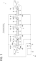
- FIG. 1 is a schematic configuration view of a pickling apparatus according to an embodiment.
- FIG. 2 is a schematic cross-sectional view of the pickling apparatus shown in FIG. 1 .
- a pickling apparatus 1 shown in FIG. 1 is a pickling apparatus for pickling a strip S of metal (for example, steel) by using an acid solution 4.
- the pickling apparatus 1 includes a pickling tank 2 for storing the acid solution 4.
- the acid solution 4 is a pickling solution for dissolving and removing a scale (oxide layer) generated on the surface of the strip S and is, for example, a solution containing acid such as hydrochloric acid, sulfuric acid, nitric acid or hydrofluoric acid.
- the pickling apparatus 1 shown in FIG. 1 includes a skid 8 and a conveyance roll 6 for conveying the strip S immersed in the acid solution 4, while guiding the strip S.
- the conveyance roll 6 may be configured to be driven by a motor (not shown) or the like to apply tension to the strip S and convey the strip S.
- the pickling apparatus 1 may be configured to convey the strip S by causing, with only catenary due to its own weight, the strip S to reach a depth at which the surrounding part is added, without including the conveyance roll 6.
- the pickling apparatus 1 shown in FIG. 1 further includes a surrounding part 10 disposed in the pickling tank 2, and an oxidant supply part 50 for supplying a liquid oxidant toward an inside of the surrounding part 10.
- the surrounding part 10 is disposed in the pickling tank 2 so as to surround the strip S immersed in the acid solution 4 in the pickling tank 2.
- the surrounding part 10 forms a passage 12 for the acid solution 4 along a conveying direction of the strip S (hereinafter, also simply referred to as the conveying direction).
- the pickling apparatus 1 may include a plurality of surrounding parts 10 disposed inside the pickling tank 2 and arranged in the conveying direction.
- the pickling apparatus 1 may include a plurality of surrounding parts 10 disposed inside the pickling tank 2 and arranged in the conveying direction.
- four surrounding parts 10 are disposed inside the pickling tank 2.
- the surrounding part 10 includes an upper plate part 20 and a lower plate part 22 disposed so as to respectively cover both faces of the strip S, and a pair of side plate parts 24, 26 disposed so as to connect the upper plate part 20 and the lower plate part 22 on both sides in a strip width direction of the strip S.
- the passage 12 for the acid solution 4 is formed by inner surfaces of the upper plate part 20, the lower plate part 22, and the side plate parts 24, 26.
- a guide part 16 for guiding the strip S being conveyed is disposed in the surrounding part 10.
- the guide part 16 may include a guide roll 17 or a receiving part 18 (such as a skid) disposed in the surrounding part 10.
- the guide part 16 includes the guide roll 17 supported by the upper plate part 20 (surrounding part 10) and the receiving part 18 supported by the lower plate part 22 (surrounding part 10).
- the oxidant supply part 50 is configured to supply a liquid oxidant for oxidizing Fe 2+ in the acid solution 4 to Fe 3+ toward the inside of the surrounding part 10.
- the oxidant supply part 50 shown in FIGs. 1 and 2 includes an oxidant tank 52 in which the liquid oxidant is stored, an oxidant supply line 53 for introducing the liquid oxidant from the oxidant tank 52 toward the inside of the surrounding part 10, and an oxidant pump 54 disposed on the oxidant supply line 53.
- the oxidant supply part 50 includes pipes 56 (56A, 56B) connected to the surrounding part 10 and is configured to supply the liquid oxidant into the surrounding part 10 via the pipes 56.
- the pipe 56A is connected to the upper plate part 20 forming the surrounding part 10.
- the pipe 56B is connected to the lower plate part 22 forming the surrounding part 10.
- the liquid oxidant a liquid having the ability to oxidize ferrous ions (Fe 2+ ) can be used.
- the liquid oxidant may be, for example, a liquid containing at least one of hydrogen peroxide solution, hypochlorous acid, ammonium peroxodisulfate (ammonium persulfate), and potassium permanganate solution.
- the liquid oxidant is supplied into the surrounding part 10 disposed so as to surround the strip S in the pickling tank 2, in the pickling tank 2, the liquid oxidant is prevented from being diffused to the outside of the surrounding part 10 and tends to remain in the vicinity of the strip S. Therefore, Fe 3+ produced by the reaction between the liquid oxidant and the acid solution 4 easily contacts the strip S, making it possible to efficiently perform pickling.
- the surrounding part 10 a flow (entrained flow) of the acid solution entrained by the strip S being conveyed is formed, and the flow velocity of the acid solution 4 is relatively high.
- the liquid oxidant since the liquid oxidant is supplied into the surrounding part 10, it is possible to increase a chance of contact between the liquid oxidant and Fe 2+ in the acid solution 4. Whereby, the oxidation reaction of Fe 2+ (Fe 3+ production reaction) by the liquid oxidant occurs easily, and it is possible to prevent the liquid oxidant from being wasted due to thermal decomposition or reaction with the acid in the acid solution.
- the acid solution 4 contains hydrochloric acid (HCl) and the liquid oxidant contains hydrogen peroxide solution (H 2 O 2 ). That is, if the liquid oxidant is supplied to the acid solution 4 in the pickling tank 2, Fe 2+ contained in the acid solution 4 is oxidized according to the following reaction formula (A). H 2 O 2 +2Fe 2+ +2HCl ⁇ 2H 2 O+2Fe 3+ +2Cl - ... (A)
- the liquid oxidant supplied to the acid solution 4 can also be consumed by a thermal decomposition reaction (reaction formula (B) below) or a reaction with the acid constituting the acid solution 4 (reaction formula (C) below).
- reaction formula (B) a thermal decomposition reaction
- reaction formula (C) a reaction with the acid constituting the acid solution 4
- reaction formula (A) oxidation reaction of Fe 2+
- reaction formula (B) thermal decomposition of the liquid oxidant
- reaction formula (C) reaction with the acid
- the strip S can be pickled more efficiently.
- the pickling apparatus 1 may include a lid part 30 covering the pickling tank 2 from above. A loss due to evaporation of the acid solution 4 in the pickling tank 2 can be suppressed by covering the pickling tank 2 from above with the lid part 30. Further, the pickling apparatus 1 may include a seal part 40 for sealing a space surrounded by the pickling tank 2 and the lid part 30. The loss due to evaporation of the acid solution 4 in the pickling tank 2 can more effectively be suppressed by providing such seal part 40.
- the lid part 30 may include the upper plate part 20 forming an upper portion of the surrounding part 10. Further, the lid part 30 may include the upper plate part 20, as well as may include a seal plate part 34 configured to be inserted from above into a tub part 42 disposed at an edge (upper end portion) of the pickling tank 2.
- the seal part 40 includes the tub part 42 and the seal plate part 34, and may be configured to seal, by immersing the seal plate part 34 in a seal liquid (water etc.) stored in the tub part 42, the space surrounded by the pickling tank 2 and the lid part 30.
- the lid part 30 is disposed to be openable and closable integrally with the upper plate part 20 forming the surrounding part 10.
- the pickling apparatus 1 may include an actuator for opening and closing the lid part 30.
- the passage 12 formed by the surrounding part 10 has a passage decreasing part 14 located downstream of an upstream end 10a of the surrounding part 10 in the conveying direction and having a smaller passage cross-sectional area than the upstream end 10a.
- the passage cross-sectional area is an area of a passage cross-section of the passage 12 orthogonal to the conveying direction.
- the passage decreasing part 14 may be formed by the above-described guide part 16 disposed in the surrounding part 10. In the exemplary embodiments shown in FIGs. 1 and 2 , the passage decreasing part 14 is formed by the guide roll 17 (guide part 16) and the receiving part 18 (guide part 16).
- the passage 12 formed by the surrounding part 10 since the passage 12 formed by the surrounding part 10 has the passage decreasing part 14 located downstream of the upstream end 10a of the surrounding part 10, a reverse flow, which is obtained by reversing the entrained flow of the acid solution 4 entrained by the strip S, at the passage decreasing part 14 (the guide roll 17 or the receiving part 18) is formed in the surrounding part 10. Since the acid solution 4 is agitated by this reverse flow, it is possible to further increase the chance of contact between the liquid oxidant and Fe 2+ in the acid solution 4. Therefore, the oxidation reaction of Fe 2+ by the liquid oxidant occurs more easily, making it possible to more efficiently pickle the strip S.
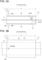
- FIGs. 3A to 8 are each a schematic view of the surrounding part 10 and the oxidant supply part 50 of the pickling apparatus according to an embodiment.
- FIGs. 3A , 4A , 5A , and 8 are cross-sectional views including the conveying direction and the up-down direction (vertical direction), and FIGs. 3B , 4B , and 5B are plan view corresponding to FIGs. 3A , 4A , and 5A , respectively.
- FIGs. 6A and 7A are front views, and FIGs. 6B and 7B are cross-sectional views along the horizontal direction corresponding to FIGs. 6A and 7A , respectively.
- the oxidant supply part 50 includes the pipes 56 (56A to 56D) connected to the surrounding part 10.
- the pipe 56 may be disposed so as to penetrate the member (the upper plate part 20, the lower plate part 22, the side plate parts 24, 26, or the like) forming the surrounding part 10.
- the pipe 56 may be supported by the pickling tank 2 or the lid part 30.
- the liquid oxidant is supplied to the inside of the surrounding part 10 via the pipe 56.
- the oxidant supply part 50 includes a nozzle 57 (57A, 57B) disposed at least partially upstream of the surrounding part 10 in the conveying direction.
- the liquid oxidant is ejected from an opening 55 of the nozzle 57 and is supplied to the inside of the surrounding part 10.
- the opening 55 of the nozzle 57 may be located upstream of the upstream end 10a of the surrounding part 10 in the conveying direction, or may be located downstream of the upstream end 10a, or may be at the same position as the upstream end 10a.
- the oxidant supply part 50 may include the pipe 56A connected to the upper plate part 20, or may include the pipe 56B connected to the lower plate part 22.
- the oxidant supply part 50 includes the pipe 56A connected to the upper plate part 20 and the pipe 56B connected to the lower plate part 22.
- the oxidant supply part 50 may include the pipe 56C or the pipe 56D connected to at least either of the side plate part 24 or 26.
- the oxidant supply part 50 includes the pipe 56C and the pipe 56D respectively connected to the side plate parts 24, 26.
- the oxidant supply part 50 may be configured to supply the liquid oxidant at a position upstream of the passage decreasing part 14 in the conveying direction.
- the liquid oxidant is supplied at the position upstream of the passage decreasing part 14 in the conveying direction via the pipe 56 or the nozzle 57 (oxidant supply part 50) connected to the surrounding part 10 at the position upstream of the guide roll 17 and the receiving part 18, which form the passage decreasing part 14, in the conveying direction.
- the liquid oxidant is thus supplied at the position upstream of the passage decreasing part 14, the acid solution 4 containing the liquid oxidant is agitated by the reverse flow formed at the passage decreasing part 14. Therefore, the chance of contact between the liquid oxidant and Fe 2+ in the acid solution 4 increases and the oxidation reaction of Fe 2+ occurs easily, making it possible to more efficiently pickle the strip S.
- the oxidant supply part 50 may be configured to supply the liquid oxidant at a position where a length from the upstream end 10a of the surrounding part 10 is at least 0 and at most L/2, where L is a length of the surrounding part 10 in the conveying direction.
- the liquid oxidant supplied into the surrounding part 10 diffuses into the acid solution 4 while traveling a relatively long distance which is not less than half the length of the surrounding part 10 inside the surrounding part 10, it is possible to increase the chance of contact between the liquid oxidant and Fe 2+ in the acid solution 4.
- the oxidant supply part 50 may include a plurality of pipes 56 connected to the surrounding part 10 at mutually different positions in the strip width direction of the strip S.
- the oxidant supply part 50 includes a plurality of pipes 56A connected to the upper plate part 20 (surrounding part 10) at the mutually different positions in the strip width direction of the strip S, and a plurality of pipes 56B connected to the lower plate part 22 (surrounding part 10) at the mutually different positions in the strip width direction of the strip S.
- the acid solution 4 mainly flows in the conveying direction of the strip S (that is, the longitudinal direction of the strip S), and thus the diffusion rate of the liquid oxidant, which is supplied to the inside of the surrounding part 10, in the strip width direction is lower than the diffusion rate in the conveying direction.
- the liquid supply agent since the liquid supply agent is supplied into the surrounding part 10 via the plurality of pipes 56 disposed at the mutually different positions in the strip width direction, the concentration of the liquid oxidant is easily equalized in the strip width direction where the diffusion rate of the liquid oxidant is low. Therefore, uniform pickling is easily performed in the strip width direction.
- the acid solution is entrained by the strip S and mainly flows in the conveying direction of the strip S (that is, the longitudinal direction of the strip S), but on a lower side of the lower plate part 22 of the surrounding part 10 and on both outer sides of the two side plate parts 24, 26 of the surrounding part 10, the acid solution tends to mainly flow in a direction opposite to the conveying direction of the strip S.
- the lid part 30 reduces the area of the free liquid level of the acid solution, and thus energy entraining the acid solution created by the traveling of the strip is used for the flux of the acid solution without being consumed by vertical movement of the free liquid level etc., and the energy is efficiently converted into the flow of the acid solution.
- the pipe 56 (oxidant supply part 50) connected to the surrounding part 10 may be provided with check valves 58 (58A, 58B).
- the check valve 58A is disposed in the pipe 56A connected to the upper plate part 20 (surrounding part 10).
- the check valve 58B is disposed in the pipe 56B connected to the lower plate part 22 (surrounding part 10).
- the oxidant supply line 53 is provided with valves 62A, 62B for adjusting the amount of the liquid oxidant supplied from the oxidant tank 52 into the surrounding part 10.
- the check valve 58 is disposed in the pipe 56 for supplying the liquid oxidant, it is possible to prevent the acid solution from entering the oxidant supply line 53 for some reason (for example, due to a decrease in supply pressure of the liquid oxidant, etc.)
- a flexible hose 60 may be disposed on the oxidant supply line 53 between the oxidant tank 52 and the pipe 56A connected to the upper plate part 20.
- the flexible hose 60 is disposed on the oxidant supply line 53 between the oxidant tank 52 and the pipe 56A connected to the upper plate part 20, the upper plate part 20 of the surrounding part 10 can smoothly be opened and closed together with the lid part 30 while maintaining the state where the surrounding part 10 and the oxidant tank 52 are connected via the pipe 56A and the flexible hose 60. Therefore, it is possible to easily perform inspection or maintenance of the inside of the pickling tank 2 and the surrounding part 10.
- the flexible hose 60 may be disposed upstream (on the oxidant tank 52 side) of the check valve 58 on the oxidant supply line 53.
- the flexible hose 60 is thus disposed upstream of the check valve 58, it is possible to prevent the acid solution from entering the flexible hose 60 and it is possible to protect the flexible hose 60 from, for example, corrosion caused by acid.
- FIGs. 9 and 10 are respectively a schematic configuration view of the pickling apparatus according to an embodiment and a schematic configuration view of the pickling apparatus according to an embodiment.
- the pickling apparatus 1 includes the pickling tank 2 for storing the acid solution 4, the surrounding part 10 disposed in the pickling tank 2, and the oxidant supply part 50 for supplying the liquid oxidant toward the inside of the surrounding part 10.
- the pickling apparatus 1 further includes an acid solution circulation line 72 configured to extract the acid solution 4 from the pickling tank 2 and return the acid solution 4 toward the inside of the surrounding part 10 in the pickling tank 2.
- the acid solution circulation line 72 is provided with an acid solution circulation pump 74.
- the acid solution 4 extracted from the pickling tank 2 is supplied to the inside of the surrounding part 10 via the acid solution circulation line 72 and a pipe 76 connected to the surrounding part 10.
- the acid solution 4 extracted from the pickling tank 2 is returned toward the inside of the surrounding part 10 via the acid solution circulation line 72, it is possible to promote the agitation of the acid solution 4 inside the surrounding part 10. Therefore, the chance of contact between the liquid oxidant supplied toward the inside of the surrounding part 10 and Fe 2+ in the acid solution 4 increases and the oxidation reaction of Fe 2+ occurs easily, making it possible to more efficiently pickle the strip S.
- the oxidant supply part 50 may include a pipe 64 connected to the acid solution circulation line 72, and may be configured to supply the liquid oxidant toward the inside of the surrounding part 10 via the acid solution circulation line 72.
- the oxidant supply part 50 includes the pipe 64 connecting the oxidant tank 52 and the acid solution circulation line 72.
- the pipe 76 connected to the surrounding part 10 and configured to return the acid solution 4 from the acid solution circulation line 72 to the inside of the surrounding part 10 also functions as the pipe 56 for supplying the liquid oxidant to the inside of the surrounding part 10.
- a portion of the acid solution circulation line 72 on the downstream side of the connection portion with the pipe 64 functions as the oxidant supply line 53.
- the liquid oxidant since the liquid oxidant is mixed into the acid solution 4 via the pipe 64 connected to the acid solution circulation line 72, the liquid oxidant can be supplied toward the inside of the surrounding part 10 with the relatively simple configuration.
- a flow (entrained flow) of the acid solution entrained by the strip being conveyed is formed, and the flow velocity of the acid solution is relatively high.
- the liquid oxidant since the liquid oxidant is supplied into the surrounding part, it is possible to increase the chance of contact between the liquid oxidant and Fe 2+ in the acid solution. Whereby, the oxidation reaction of Fe 2+ (Fe 3+ production reaction) by the liquid oxidant occurs easily, and it is possible to prevent the liquid oxidant from being wasted due to thermal decomposition or reaction with the acid in the acid solution.
- the strip can be pickled more efficiently.
- the surrounding part forms a passage (12) for the acid solution along a conveying direction of the strip, and the passage has a passage decreasing part located downstream of an upstream end (10a) of the surrounding part in the conveying direction and having a smaller passage cross-sectional area than the upstream end.
- the pickling apparatus includes: a guide part (16) disposed in the surrounding part and configured to guide the strip.
- the passage decreasing part is formed by the guide part.
- the oxidant supply part is configured to supply the liquid oxidant at a position upstream of the passage decreasing part in the conveying direction.
- the oxidant supply part is configured to supply the liquid oxidant at a position where a length from an upstream end of the surrounding part is at least 0 and at most L/2, where L is a length of the surrounding part in the conveying direction.
- the liquid oxidant supplied at the relatively upstream position where the length from the upstream end of the surrounding part is at least 0 and at most L/2 the liquid oxidant supplied into the surrounding part diffuses into the acid solution while traveling a relatively long distance which is not less than half the length of the surrounding part inside the surrounding part, it is possible to increase the chance of contact between the liquid oxidant and Fe 2+ in the acid solution.
- the oxidant supply part includes at least one pipe (56) connected to the surrounding part and is configured to supply the liquid oxidant into the surrounding part via the pipe.
- the strip can be pickled more efficiently as described in the above (1).
- the at least one pipe includes a plurality of pipes connected to the surrounding part at mutually different positions in a strip width direction of the strip.
- the acid solution mainly flows in the conveying direction of the strip (that is, the longitudinal direction of the strip), and thus the diffusion rate of the liquid oxidant, which is supplied to the inside of the surrounding part, in the strip width direction is lower than the diffusion rate in the conveying direction.
- the liquid supply agent since the liquid supply agent is supplied into the surrounding part via the plurality of pipes disposed at the mutually different positions in the strip width direction, the concentration of the liquid oxidant is easily equalized in the strip width direction where the diffusion rate of the liquid oxidant is low. Therefore, uniform pickling is easily performed in the strip width direction.
- the pickling apparatus includes: a check valve (58) disposed in the at least one pipe.
- the surrounding part includes an upper plate part (20) and a lower plate part (22) disposed so as to cover both faces of the strip, and a pair of side plate parts (24, 26) disposed so as to connect the upper plate part and the lower plate part on both sides of the strip.
- the strip can be pickled more efficiently as described in the above (1).
- the oxidant supply part includes a pipe (56A, 56B) penetrating at least either of the upper plate part or the lower plate part.
- the liquid oxidant can be supplied from above or below the strip inside the surrounding part via the pipe connected to the upper plate part or the lower plate part. Whereby, the strip can be pickled more efficiently as described above in (1).
- the oxidant supply part includes a pipe (56C, 56D) penetrating at least either of the pair of side plate parts.
- the liquid oxidant can be supplied from the side of the strip inside the surrounding part via the pipe connected to at least either of the pair of side plate parts. Whereby, the strip can be pickled more efficiently as described above in (1).
- the pickling apparatus includes: a lid part (30) covering the pickling tank from above.
- the lid part is disposed to be openable and closable integrally with the upper plate part.
- the oxidant supply part includes: an oxidant tank (52) for storing the liquid oxidant; a pipe (56A) connected to the upper plate part; and a flexible hose (60) disposed between the oxidant tank and the pipe.
- the upper plate part of the surrounding part can smoothly be opened and closed together with the lid part while maintaining the state where the surrounding part and the oxidant tank are connected via the pipe and the flexible hose.
- the pickling apparatus includes: an acid solution circulation line (72) configured to extract the acid solution from the pickling tank and return the acid solution toward the inside of the surrounding part in the pickling tank.
- the oxidant supply part includes a pipe (64) connected to the acid solution circulation line, and is configured to supply the liquid oxidant toward the inside of the surrounding part via the acid solution circulation line.
- the above configuration (1) since the liquid oxidant is mixed into the acid solution via the pipe connected to the acid solution circulation line, the above configuration (1) can be realized with the relatively simple configuration.
- a pickling method is a pickling method for pickling a strip of metal being conveyed, including: a step of conveying the strip in a state where the strip is immersed in an acid solution stored in a pickling tank and the strip is surrounded by a surrounding part disposed in the pickling tank; and a step of supplying a liquid oxidant toward an inside of the surrounding part.
- the liquid oxidant is supplied into the surrounding part disposed so as to surround the strip in the pickling tank, in the pickling tank, the liquid oxidant is prevented from being diffused to the outside of the surrounding part and tends to remain in the vicinity of the strip. Therefore, Fe 3+ produced by the reaction between the liquid oxidant and the acid solution easily contacts the strip, making it possible to efficiently perform pickling.
- a flow (entrained flow) of the acid solution entrained by the strip being conveyed is formed, and the flow velocity of the acid solution is relatively high.
- the liquid oxidant since the liquid oxidant is supplied into the surrounding part, it is possible to increase the chance of contact between the liquid oxidant and Fe 2+ in the acid solution. Whereby, the oxidation reaction of Fe 2+ (Fe 3+ production reaction) by the liquid oxidant occurs easily, and it is possible to prevent the liquid oxidant from being wasted due to thermal decomposition or reaction with the acid in the acid solution.
- the strip can be pickled more efficiently.
- Embodiments of the present invention were described in detail above, but the present invention is not limited thereto, and also includes an embodiment obtained by modifying the above-described embodiments and an embodiment obtained by combining these embodiments as appropriate.
- an expression of relative or absolute arrangement such as “in a direction”, “along a direction”, “parallel”, “orthogonal”, “centered”, “concentric” and “coaxial” shall not be construed as indicating only the arrangement in a strict literal sense, but also includes a state where the arrangement is relatively displaced by a tolerance, or by an angle or a distance whereby it is possible to achieve the same function.
- an expression of an equal state such as “same” “equal” and “uniform” shall not be construed as indicating only the state in which the feature is strictly equal, but also includes a state in which there is a tolerance or a difference that can still achieve the same function.
- an expression of a shape such as a rectangular shape or a cylindrical shape shall not be construed as only the geometrically strict shape, but also includes a shape with unevenness or chamfered corners within the range in which the same effect can be achieved.
Landscapes
- Chemical & Material Sciences (AREA)
- Chemical Kinetics & Catalysis (AREA)
- General Chemical & Material Sciences (AREA)
- Engineering & Computer Science (AREA)
- Materials Engineering (AREA)
- Mechanical Engineering (AREA)
- Metallurgy (AREA)
- Organic Chemistry (AREA)
- Cleaning And De-Greasing Of Metallic Materials By Chemical Methods (AREA)
Abstract
A pickling apparatus for pickling a strip of metal being conveyed is equipped with: a pickling tank for storing an acid solution; a surrounding part disposed in the pickling tank so as to surround the strip immersed in the acid solution in the pickling tank; and an oxidant supply part for supplying a liquid oxidant toward an inside of the surrounding part.
Description
- The present disclosure relates to a pickling apparatus and a pickling method.
- It is known that, in pickling a strip of metal (such as steel), a pickling speed is increased by regulating the concentration of ferric ions (Fe3+) contained in an acid solution, and a method for regulating the concentration of Fe3+ in the acid solution is proposed.
- For example,
Patent Document 1 describes that an acid solution in a pickling tank is circulated via a conduit connected to the pickling tank and hydrogen peroxide solution is supplied to the conduit, thereby oxidizing Fe2+ in the acid solution to Fe3+ and increasing the concentration of Fe3+ in the acid solution. - Patent Document 1:
JPH9-170090A - Meanwhile, depending on how the liquid oxidant such as hydrogen peroxide solution is supplied to the acid solution, the liquid oxidant is likely to be consumed in a reaction different from the oxidation of Fe2+. Since it is necessary to increase the supply amount of a liquid supply agent in order to appropriately oxidize Fe2+, it is difficult to perform efficient pickling.
- In view of the above, an object of at least one embodiment of the present invention is to provide a pickling apparatus and a pickling method which are capable of pickling a strip of metal more efficiently.
- A pickling apparatus according to at least one embodiment of the present invention is a pickling apparatus for pickling a strip of metal being conveyed, including: a pickling tank for storing an acid solution; a surrounding part disposed in the pickling tank so as to surround the strip immersed in the acid solution in the pickling tank; and an oxidant supply part for supplying a liquid oxidant toward an inside of the surrounding part.
- Further, a pickling method according to at least one embodiment of the present invention is a pickling method for pickling a strip of metal being conveyed, including: a step of conveying the strip in a state where the strip is immersed in an acid solution stored in a pickling tank and the strip is surrounded by a surrounding part disposed in the pickling tank; and a step of supplying a liquid oxidant toward an inside of the surrounding part.
- According to at least one embodiment of the present invention, in view of the above, the at least one embodiment of the present invention provides a pickling apparatus and a pickling method which are capable of pickling a strip of metal more efficiently.
-
-
FIG. 1 is a schematic configuration view of a pickling apparatus according to an embodiment. -
FIG. 2 is a schematic cross-sectional view of the pickling apparatus shown inFIG. 1 . -
FIG. 3A is a schematic view of a surrounding part and an oxidant supply part of the pickling apparatus according to an embodiment. -
FIG. 3B is a schematic view of the surrounding part and the oxidant supply part of the pickling apparatus according to an embodiment. -
FIG. 4A is a schematic view of the surrounding part and the oxidant supply part of the pickling apparatus according to an embodiment. -
FIG. 4B is a schematic view of the surrounding part and the oxidant supply part of the pickling apparatus according to an embodiment. -
FIG. 5A is a schematic view of the surrounding part and the oxidant supply part of the pickling apparatus according to an embodiment. -
FIG. 5B is a schematic view of the surrounding part and the oxidant supply part of the pickling apparatus according to an embodiment. -
FIG. 6A is a schematic view of the surrounding part and the oxidant supply part of the pickling apparatus according to an embodiment. -
FIG. 6B is a schematic view of the surrounding part and the oxidant supply part of the pickling apparatus according to an embodiment. -
FIG. 7A is a schematic view of the surrounding part and the oxidant supply part of the pickling apparatus according to an embodiment. -
FIG. 7B is a schematic view of the surrounding part and the oxidant supply part of the pickling apparatus according to an embodiment. -
FIG. 8 is a schematic view of the surrounding part and the oxidant supply part of the pickling apparatus according to an embodiment. -
FIG. 9 is a schematic configuration view of the pickling apparatus according to an embodiment. -
FIG. 10 is a schematic configuration view of the pickling apparatus according to an embodiment. - Some embodiments of the present invention will be described below with reference to the accompanying drawings. It is intended, however, that unless particularly identified, dimensions, materials, shapes, relative positions and the like of components described or shown in the drawings as the embodiments shall be interpreted as illustrative only and not intended to limit the scope of the present invention.
-
FIG. 1 is a schematic configuration view of a pickling apparatus according to an embodiment.FIG. 2 is a schematic cross-sectional view of the pickling apparatus shown inFIG. 1 . - A
pickling apparatus 1 shown inFIG. 1 is a pickling apparatus for pickling a strip S of metal (for example, steel) by using anacid solution 4. As shown inFIG. 1 , thepickling apparatus 1 includes apickling tank 2 for storing theacid solution 4. Theacid solution 4 is a pickling solution for dissolving and removing a scale (oxide layer) generated on the surface of the strip S and is, for example, a solution containing acid such as hydrochloric acid, sulfuric acid, nitric acid or hydrofluoric acid. - The
pickling apparatus 1 shown inFIG. 1 includes a skid 8 and a conveyance roll 6 for conveying the strip S immersed in theacid solution 4, while guiding the strip S. The conveyance roll 6 may be configured to be driven by a motor (not shown) or the like to apply tension to the strip S and convey the strip S. Thepickling apparatus 1 may be configured to convey the strip S by causing, with only catenary due to its own weight, the strip S to reach a depth at which the surrounding part is added, without including the conveyance roll 6. - The
pickling apparatus 1 shown inFIG. 1 further includes a surroundingpart 10 disposed in thepickling tank 2, and anoxidant supply part 50 for supplying a liquid oxidant toward an inside of the surroundingpart 10. - The surrounding
part 10 is disposed in thepickling tank 2 so as to surround the strip S immersed in theacid solution 4 in thepickling tank 2. The surroundingpart 10 forms apassage 12 for theacid solution 4 along a conveying direction of the strip S (hereinafter, also simply referred to as the conveying direction). - As shown in
FIG. 1 , thepickling apparatus 1 may include a plurality of surroundingparts 10 disposed inside thepickling tank 2 and arranged in the conveying direction. In the exemplary embodiment shown inFIG. 1 , four surroundingparts 10 are disposed inside thepickling tank 2. - In some embodiments, as shown in
FIG. 2 , the surroundingpart 10 includes anupper plate part 20 and alower plate part 22 disposed so as to respectively cover both faces of the strip S, and a pair ofside plate parts upper plate part 20 and thelower plate part 22 on both sides in a strip width direction of the strip S. Thepassage 12 for theacid solution 4 is formed by inner surfaces of theupper plate part 20, thelower plate part 22, and theside plate parts - In some embodiments, as shown in
FIGs. 1 and2 , aguide part 16 for guiding the strip S being conveyed is disposed in the surroundingpart 10. Theguide part 16 may include aguide roll 17 or a receiving part 18 (such as a skid) disposed in the surroundingpart 10. In the exemplary embodiments shown inFIGs. 1 and2 , theguide part 16 includes theguide roll 17 supported by the upper plate part 20 (surrounding part 10) and thereceiving part 18 supported by the lower plate part 22 (surrounding part 10). - The
oxidant supply part 50 is configured to supply a liquid oxidant for oxidizing Fe2+ in theacid solution 4 to Fe3+ toward the inside of the surroundingpart 10. Theoxidant supply part 50 shown inFIGs. 1 and2 includes anoxidant tank 52 in which the liquid oxidant is stored, anoxidant supply line 53 for introducing the liquid oxidant from theoxidant tank 52 toward the inside of the surroundingpart 10, and anoxidant pump 54 disposed on theoxidant supply line 53. - In the exemplary embodiments shown in
FIGs. 1 and2 , theoxidant supply part 50 includes pipes 56 (56A, 56B) connected to the surroundingpart 10 and is configured to supply the liquid oxidant into the surroundingpart 10 via the pipes 56. In the exemplary embodiments shown inFIGs. 1 and2 , thepipe 56A is connected to theupper plate part 20 forming the surroundingpart 10. Further, thepipe 56B is connected to thelower plate part 22 forming the surroundingpart 10. - As the liquid oxidant, a liquid having the ability to oxidize ferrous ions (Fe2+) can be used. The liquid oxidant may be, for example, a liquid containing at least one of hydrogen peroxide solution, hypochlorous acid, ammonium peroxodisulfate (ammonium persulfate), and potassium permanganate solution.
- In the
pickling apparatus 1 according to the above-described embodiments, since the liquid oxidant is supplied into the surroundingpart 10 disposed so as to surround the strip S in thepickling tank 2, in thepickling tank 2, the liquid oxidant is prevented from being diffused to the outside of the surroundingpart 10 and tends to remain in the vicinity of the strip S. Therefore, Fe3+ produced by the reaction between the liquid oxidant and theacid solution 4 easily contacts the strip S, making it possible to efficiently perform pickling. - Further, in the surrounding
part 10, a flow (entrained flow) of the acid solution entrained by the strip S being conveyed is formed, and the flow velocity of theacid solution 4 is relatively high. In this regard, in the above-described embodiments, since the liquid oxidant is supplied into the surroundingpart 10, it is possible to increase a chance of contact between the liquid oxidant and Fe2+ in theacid solution 4. Whereby, the oxidation reaction of Fe2+ (Fe3+ production reaction) by the liquid oxidant occurs easily, and it is possible to prevent the liquid oxidant from being wasted due to thermal decomposition or reaction with the acid in the acid solution. - This will be described using an example in which the
acid solution 4 contains hydrochloric acid (HCl) and the liquid oxidant contains hydrogen peroxide solution (H2O2). That is, if the liquid oxidant is supplied to theacid solution 4 in thepickling tank 2, Fe2+ contained in theacid solution 4 is oxidized according to the following reaction formula (A).
H2O2+2Fe2++2HCl→2H2O+2Fe3++2Cl- ... (A)
- On the other hand, the liquid oxidant supplied to the
acid solution 4 can also be consumed by a thermal decomposition reaction (reaction formula (B) below) or a reaction with the acid constituting the acid solution 4 (reaction formula (C) below).
2H2O2→2H2O+O2 ... (B)
H2O2+2HCl→2H2O+Cl2 ... (C)
- Herein, if the chance of contact between the liquid oxidant and Fe2+ in the
acid solution 4 increases, the oxidation reaction of Fe2+ (reaction formula (A)) occurs relatively easily compared to the thermal decomposition of the liquid oxidant (reaction formula (B)) and the reaction with the acid (reaction formula (C)), and it is possible to prevent the liquid oxidant from being consumed without contributing to the oxidation reaction of Fe2+ due to the reaction of reaction formula (B) or reaction formula (C). - Therefore, according to the above-described embodiments, the strip S can be pickled more efficiently.
- As shown in
FIGs. 1 and2 , thepickling apparatus 1 may include alid part 30 covering thepickling tank 2 from above. A loss due to evaporation of theacid solution 4 in thepickling tank 2 can be suppressed by covering thepickling tank 2 from above with thelid part 30. Further, thepickling apparatus 1 may include aseal part 40 for sealing a space surrounded by thepickling tank 2 and thelid part 30. The loss due to evaporation of theacid solution 4 in thepickling tank 2 can more effectively be suppressed by providingsuch seal part 40. - As shown in
FIG. 2 , thelid part 30 may include theupper plate part 20 forming an upper portion of the surroundingpart 10. Further, thelid part 30 may include theupper plate part 20, as well as may include aseal plate part 34 configured to be inserted from above into atub part 42 disposed at an edge (upper end portion) of thepickling tank 2. Theseal part 40 includes thetub part 42 and theseal plate part 34, and may be configured to seal, by immersing theseal plate part 34 in a seal liquid (water etc.) stored in thetub part 42, the space surrounded by thepickling tank 2 and thelid part 30. - In the exemplary embodiment shown in
FIG. 2 , thelid part 30 is disposed to be openable and closable integrally with theupper plate part 20 forming the surroundingpart 10. Thepickling apparatus 1 may include an actuator for opening and closing thelid part 30. - In some embodiments, the
passage 12 formed by the surroundingpart 10 has apassage decreasing part 14 located downstream of anupstream end 10a of the surroundingpart 10 in the conveying direction and having a smaller passage cross-sectional area than theupstream end 10a. Herein, the passage cross-sectional area is an area of a passage cross-section of thepassage 12 orthogonal to the conveying direction. Thepassage decreasing part 14 may be formed by the above-describedguide part 16 disposed in the surroundingpart 10. In the exemplary embodiments shown inFIGs. 1 and2 , thepassage decreasing part 14 is formed by the guide roll 17 (guide part 16) and the receiving part 18 (guide part 16). - In the above-described embodiments, since the
passage 12 formed by the surroundingpart 10 has thepassage decreasing part 14 located downstream of theupstream end 10a of the surroundingpart 10, a reverse flow, which is obtained by reversing the entrained flow of theacid solution 4 entrained by the strip S, at the passage decreasing part 14 (theguide roll 17 or the receiving part 18) is formed in the surroundingpart 10. Since theacid solution 4 is agitated by this reverse flow, it is possible to further increase the chance of contact between the liquid oxidant and Fe2+ in theacid solution 4. Therefore, the oxidation reaction of Fe2+ by the liquid oxidant occurs more easily, making it possible to more efficiently pickle the strip S. -
FIGs. 3A to 8 are each a schematic view of the surroundingpart 10 and theoxidant supply part 50 of the pickling apparatus according to an embodiment.FIGs. 3A ,4A ,5A , and8 are cross-sectional views including the conveying direction and the up-down direction (vertical direction), andFIGs. 3B ,4B , and5B are plan view corresponding toFIGs. 3A ,4A , and5A , respectively. Further,FIGs. 6A and7A are front views, andFIGs. 6B and7B are cross-sectional views along the horizontal direction corresponding toFIGs. 6A and7A , respectively. - In the exemplary embodiments shown in
FIGs. 3A to 7B , theoxidant supply part 50 includes the pipes 56 (56A to 56D) connected to the surroundingpart 10. The pipe 56 may be disposed so as to penetrate the member (theupper plate part 20, thelower plate part 22, theside plate parts part 10. The pipe 56 may be supported by thepickling tank 2 or thelid part 30. The liquid oxidant is supplied to the inside of the surroundingpart 10 via the pipe 56. - In the exemplary embodiment shown in
FIG. 8 , theoxidant supply part 50 includes a nozzle 57 (57A, 57B) disposed at least partially upstream of the surroundingpart 10 in the conveying direction. The liquid oxidant is ejected from anopening 55 of the nozzle 57 and is supplied to the inside of the surroundingpart 10. As shown inFIG. 8 , theopening 55 of the nozzle 57 may be located upstream of theupstream end 10a of the surroundingpart 10 in the conveying direction, or may be located downstream of theupstream end 10a, or may be at the same position as theupstream end 10a. - In some embodiments, the
oxidant supply part 50 may include thepipe 56A connected to theupper plate part 20, or may include thepipe 56B connected to thelower plate part 22. In the exemplary embodiments shown inFIGs. 3A to 5B , theoxidant supply part 50 includes thepipe 56A connected to theupper plate part 20 and thepipe 56B connected to thelower plate part 22. - In some embodiments, the
oxidant supply part 50 may include thepipe 56C or thepipe 56D connected to at least either of theside plate part FIGs. 6A to 7B , theoxidant supply part 50 includes thepipe 56C and thepipe 56D respectively connected to theside plate parts - As shown in
FIGs. 5A to 8 , theoxidant supply part 50 may be configured to supply the liquid oxidant at a position upstream of thepassage decreasing part 14 in the conveying direction. In the exemplary embodiments shown inFIGs. 5A to 8 , the liquid oxidant is supplied at the position upstream of thepassage decreasing part 14 in the conveying direction via the pipe 56 or the nozzle 57 (oxidant supply part 50) connected to the surroundingpart 10 at the position upstream of theguide roll 17 and the receivingpart 18, which form thepassage decreasing part 14, in the conveying direction. - Since the liquid oxidant is thus supplied at the position upstream of the
passage decreasing part 14, theacid solution 4 containing the liquid oxidant is agitated by the reverse flow formed at thepassage decreasing part 14. Therefore, the chance of contact between the liquid oxidant and Fe2+ in theacid solution 4 increases and the oxidation reaction of Fe2+ occurs easily, making it possible to more efficiently pickle the strip S. - In some embodiments, for example, as shown in
FIGs. 3A to 4B , andFIGs. 6A and 6B , theoxidant supply part 50 may be configured to supply the liquid oxidant at a position where a length from theupstream end 10a of the surroundingpart 10 is at least 0 and at most L/2, where L is a length of the surroundingpart 10 in the conveying direction. - By thus supplying the liquid oxidant at the relatively upstream position where the length from the
upstream end 10a of the surroundingpart 10 is at least 0 and at most L/2, the liquid oxidant supplied into the surroundingpart 10 diffuses into theacid solution 4 while traveling a relatively long distance which is not less than half the length of the surroundingpart 10 inside the surroundingpart 10, it is possible to increase the chance of contact between the liquid oxidant and Fe2+ in theacid solution 4. - In some embodiments, for example, as shown in
FIGs. 4A and 4B , theoxidant supply part 50 may include a plurality of pipes 56 connected to the surroundingpart 10 at mutually different positions in the strip width direction of the strip S. In the exemplary embodiments shown inFIGs. 4A and 4B , theoxidant supply part 50 includes a plurality ofpipes 56A connected to the upper plate part 20 (surrounding part 10) at the mutually different positions in the strip width direction of the strip S, and a plurality ofpipes 56B connected to the lower plate part 22 (surrounding part 10) at the mutually different positions in the strip width direction of the strip S. - In the surrounding
part 10, theacid solution 4 mainly flows in the conveying direction of the strip S (that is, the longitudinal direction of the strip S), and thus the diffusion rate of the liquid oxidant, which is supplied to the inside of the surroundingpart 10, in the strip width direction is lower than the diffusion rate in the conveying direction. According to the above-described embodiments, since the liquid supply agent is supplied into the surroundingpart 10 via the plurality of pipes 56 disposed at the mutually different positions in the strip width direction, the concentration of the liquid oxidant is easily equalized in the strip width direction where the diffusion rate of the liquid oxidant is low. Therefore, uniform pickling is easily performed in the strip width direction. In the surroundingpart 10, the acid solution is entrained by the strip S and mainly flows in the conveying direction of the strip S (that is, the longitudinal direction of the strip S), but on a lower side of thelower plate part 22 of the surroundingpart 10 and on both outer sides of the twoside plate parts part 10, the acid solution tends to mainly flow in a direction opposite to the conveying direction of the strip S. Further, by positioning thelid part 30 such that theupper plate part 10 of thelid part 30 is below a free liquid level of the acid solution, thelid part 30 reduces the area of the free liquid level of the acid solution, and thus energy entraining the acid solution created by the traveling of the strip is used for the flux of the acid solution without being consumed by vertical movement of the free liquid level etc., and the energy is efficiently converted into the flow of the acid solution. - In some embodiments, for example, as shown in
FIG. 2 , the pipe 56 (oxidant supply part 50) connected to the surroundingpart 10 may be provided with check valves 58 (58A, 58B). In the exemplary embodiment shown inFIG. 2 , thecheck valve 58A is disposed in thepipe 56A connected to the upper plate part 20 (surrounding part 10). Further, thecheck valve 58B is disposed in thepipe 56B connected to the lower plate part 22 (surrounding part 10). InFIG. 2 , theoxidant supply line 53 is provided withvalves oxidant tank 52 into the surroundingpart 10. - According to the above-described embodiment, since the check valve 58 is disposed in the pipe 56 for supplying the liquid oxidant, it is possible to prevent the acid solution from entering the
oxidant supply line 53 for some reason (for example, due to a decrease in supply pressure of the liquid oxidant, etc.) - In some embodiments, for example, as shown in
FIG. 2 , aflexible hose 60 may be disposed on theoxidant supply line 53 between theoxidant tank 52 and thepipe 56A connected to theupper plate part 20. - In the above-described embodiment, since the
flexible hose 60 is disposed on theoxidant supply line 53 between theoxidant tank 52 and thepipe 56A connected to theupper plate part 20, theupper plate part 20 of the surroundingpart 10 can smoothly be opened and closed together with thelid part 30 while maintaining the state where the surroundingpart 10 and theoxidant tank 52 are connected via thepipe 56A and theflexible hose 60. Therefore, it is possible to easily perform inspection or maintenance of the inside of thepickling tank 2 and the surroundingpart 10. - In some embodiments, for example, as shown in
FIG. 2 , theflexible hose 60 may be disposed upstream (on theoxidant tank 52 side) of the check valve 58 on theoxidant supply line 53. - Since the
flexible hose 60 is thus disposed upstream of the check valve 58, it is possible to prevent the acid solution from entering theflexible hose 60 and it is possible to protect theflexible hose 60 from, for example, corrosion caused by acid. -
FIGs. 9 and10 are respectively a schematic configuration view of the pickling apparatus according to an embodiment and a schematic configuration view of the pickling apparatus according to an embodiment. - In the exemplary embodiments shown in
FIGs. 9 and10 , as with thepickling apparatus 1 shown inFIG. 1 , thepickling apparatus 1 includes thepickling tank 2 for storing theacid solution 4, the surroundingpart 10 disposed in thepickling tank 2, and theoxidant supply part 50 for supplying the liquid oxidant toward the inside of the surroundingpart 10. - In the exemplary embodiments shown in
FIGs. 9 and10 , thepickling apparatus 1 further includes an acidsolution circulation line 72 configured to extract theacid solution 4 from thepickling tank 2 and return theacid solution 4 toward the inside of the surroundingpart 10 in thepickling tank 2. The acidsolution circulation line 72 is provided with an acidsolution circulation pump 74. Theacid solution 4 extracted from thepickling tank 2 is supplied to the inside of the surroundingpart 10 via the acidsolution circulation line 72 and apipe 76 connected to the surroundingpart 10. - According to the above-described embodiments, since the
acid solution 4 extracted from thepickling tank 2 is returned toward the inside of the surroundingpart 10 via the acidsolution circulation line 72, it is possible to promote the agitation of theacid solution 4 inside the surroundingpart 10. Therefore, the chance of contact between the liquid oxidant supplied toward the inside of the surroundingpart 10 and Fe2+ in theacid solution 4 increases and the oxidation reaction of Fe2+ occurs easily, making it possible to more efficiently pickle the strip S. - In some embodiments, for example, as shown in
FIG. 10 , theoxidant supply part 50 may include apipe 64 connected to the acidsolution circulation line 72, and may be configured to supply the liquid oxidant toward the inside of the surroundingpart 10 via the acidsolution circulation line 72. In the exemplary embodiment shown inFIG. 10 , theoxidant supply part 50 includes thepipe 64 connecting theoxidant tank 52 and the acidsolution circulation line 72. Further, in the exemplary embodiment shown inFIG. 10 , thepipe 76 connected to the surroundingpart 10 and configured to return theacid solution 4 from the acidsolution circulation line 72 to the inside of the surroundingpart 10 also functions as the pipe 56 for supplying the liquid oxidant to the inside of the surroundingpart 10. Furthermore, a portion of the acidsolution circulation line 72 on the downstream side of the connection portion with thepipe 64 functions as theoxidant supply line 53. - According to the above-described embodiments, since the liquid oxidant is mixed into the
acid solution 4 via thepipe 64 connected to the acidsolution circulation line 72, the liquid oxidant can be supplied toward the inside of the surroundingpart 10 with the relatively simple configuration. - Hereinafter, the overview of the pickling apparatus and the pickling method according to some embodiments will be described.
- (1) A pickling apparatus (1) according to at least one embodiment of the present invention is a pickling apparatus for pickling a strip (S) of metal being conveyed, including: a pickling tank (2) for storing an acid solution (4); a surrounding part (10) disposed in the pickling tank so as to surround the strip immersed in the acid solution in the pickling tank; and an oxidant supply part (50) for supplying a liquid oxidant toward an inside of the surrounding part.
- In the above configuration (1), since the liquid oxidant is supplied into the surrounding part disposed so as to surround the strip in the pickling tank, in the pickling tank, the liquid oxidant is prevented from being diffused to the outside of the surrounding part and tends to remain in the vicinity of the strip. Therefore, Fe3+ produced by the reaction between the liquid oxidant and the acid solution easily contacts the strip, making it possible to efficiently perform pickling.
- Further, in the surrounding part, a flow (entrained flow) of the acid solution entrained by the strip being conveyed is formed, and the flow velocity of the acid solution is relatively high. In this regard, in the above configuration (1), since the liquid oxidant is supplied into the surrounding part, it is possible to increase the chance of contact between the liquid oxidant and Fe2+ in the acid solution. Whereby, the oxidation reaction of Fe2+ (Fe3+ production reaction) by the liquid oxidant occurs easily, and it is possible to prevent the liquid oxidant from being wasted due to thermal decomposition or reaction with the acid in the acid solution.
- Therefore, according to the above configuration (1), the strip can be pickled more efficiently.
- (2) In some embodiments, in the above configuration (1), the surrounding part forms a passage (12) for the acid solution along a conveying direction of the strip, and the passage has a passage decreasing part located downstream of an upstream end (10a) of the surrounding part in the conveying direction and having a smaller passage cross-sectional area than the upstream end.
- According to the above configuration (2), since the passage formed by the surrounding part has the passage decreasing part located downstream of the upstream end, a reverse flow, which is obtained by reversing the entrained flow of the acid solution described above, at the passage decreasing part is formed in the surrounding part. Since the acid solution is agitated by this reverse flow, it is possible to further increase the chance of contact between the liquid oxidant and Fe2+ in the acid solution. Therefore, the oxidation reaction of Fe2+ by the liquid oxidant occurs more easily, making it possible to more efficiently pickle the strip.
- (3) In some embodiments, in the above configuration (2), the pickling apparatus includes: a guide part (16) disposed in the surrounding part and configured to guide the strip. The passage decreasing part is formed by the guide part.
- According to the above configuration (3), since the passage decreasing part is formed using the guide part disposed in the surrounding part, it is possible to achieve efficient pickling of the strip with the simple configuration.
- (4) In some embodiments, in the above configuration (2) or (3), the oxidant supply part is configured to supply the liquid oxidant at a position upstream of the passage decreasing part in the conveying direction.
- According to the above configuration (4), since the liquid oxidant is supplied at the position upstream of the passage decreasing part, the acid solution containing the liquid oxidant is agitated by the reverse flow formed at the passage decreasing part. Therefore, the chance of contact between the liquid oxidant and Fe2+ in the acid solution increases and the oxidation reaction of Fe2+ occurs easily, making it possible to more efficiently pickle the strip.
- (5) In some embodiments, in any of the above configurations (1) to (4), the oxidant supply part is configured to supply the liquid oxidant at a position where a length from an upstream end of the surrounding part is at least 0 and at most L/2, where L is a length of the surrounding part in the conveying direction.
- According to the above configuration (5), since the liquid oxidant is supplied at the relatively upstream position where the length from the upstream end of the surrounding part is at least 0 and at most L/2, the liquid oxidant supplied into the surrounding part diffuses into the acid solution while traveling a relatively long distance which is not less than half the length of the surrounding part inside the surrounding part, it is possible to increase the chance of contact between the liquid oxidant and Fe2+ in the acid solution.
- (6) In some embodiments, in any of the above configurations (1) to (5), the oxidant supply part includes at least one pipe (56) connected to the surrounding part and is configured to supply the liquid oxidant into the surrounding part via the pipe.
- According to the above configuration (6), by supplying the liquid oxidant into the surrounding part via the pipe connected to the surrounding part, the strip can be pickled more efficiently as described in the above (1).
- (7) In some embodiments, in the above configuration (6), the at least one pipe includes a plurality of pipes connected to the surrounding part at mutually different positions in a strip width direction of the strip.
- In the surrounding part, the acid solution mainly flows in the conveying direction of the strip (that is, the longitudinal direction of the strip), and thus the diffusion rate of the liquid oxidant, which is supplied to the inside of the surrounding part, in the strip width direction is lower than the diffusion rate in the conveying direction. According to the above configuration (7), since the liquid supply agent is supplied into the surrounding part via the plurality of pipes disposed at the mutually different positions in the strip width direction, the concentration of the liquid oxidant is easily equalized in the strip width direction where the diffusion rate of the liquid oxidant is low. Therefore, uniform pickling is easily performed in the strip width direction.
- (8) In some embodiments, in the above configuration (1), the pickling apparatus includes: a check valve (58) disposed in the at least one pipe.
- According to the above configuration (8), since the check valve is disposed in the pipe for supplying the liquid oxidant, it is possible to prevent the acid solution from entering the liquid oxidant supply line for some reason.
- (9) In some embodiments, in any of the above configurations (1) to (8), the surrounding part includes an upper plate part (20) and a lower plate part (22) disposed so as to cover both faces of the strip, and a pair of side plate parts (24, 26) disposed so as to connect the upper plate part and the lower plate part on both sides of the strip.
- According to the above configuration (9), with the surrounding part of the simple configuration including the upper plate part, the lower plate part, and the pair of side plate parts, the strip can be pickled more efficiently as described in the above (1).
- (10) In some embodiments, in the above configuration (9), the oxidant supply part includes a pipe (56A, 56B) penetrating at least either of the upper plate part or the lower plate part.
- According to the above configuration (10), the liquid oxidant can be supplied from above or below the strip inside the surrounding part via the pipe connected to the upper plate part or the lower plate part. Whereby, the strip can be pickled more efficiently as described above in (1).
- (11) In some embodiments, in the above configuration (9) or (10), the oxidant supply part includes a pipe (56C, 56D) penetrating at least either of the pair of side plate parts.
- According to the above configuration (11), the liquid oxidant can be supplied from the side of the strip inside the surrounding part via the pipe connected to at least either of the pair of side plate parts. Whereby, the strip can be pickled more efficiently as described above in (1).
- (12) In some embodiments, in any of the above configurations (9) to (11), the pickling apparatus includes: a lid part (30) covering the pickling tank from above. The lid part is disposed to be openable and closable integrally with the upper plate part. The oxidant supply part includes: an oxidant tank (52) for storing the liquid oxidant; a pipe (56A) connected to the upper plate part; and a flexible hose (60) disposed between the oxidant tank and the pipe.
- According to the above configuration (12), since the flexible hose is disposed between the oxidant tank and the pipe connected to the upper plate part, the upper plate part of the surrounding part can smoothly be opened and closed together with the lid part while maintaining the state where the surrounding part and the oxidant tank are connected via the pipe and the flexible hose.
- (13) In some embodiments, in any of the above configurations (1) to (12), the pickling apparatus includes: an acid solution circulation line (72) configured to extract the acid solution from the pickling tank and return the acid solution toward the inside of the surrounding part in the pickling tank.
- According to the above configuration (13), since the acid solution is returned toward the inside of the surrounding part via the acid solution circulation line, it is possible to promote the agitation of the acid solution inside the surrounding part. Therefore, the chance of contact between the liquid oxidant supplied toward the inside of the surrounding part and Fe2+ in the acid solution increases and the oxidation reaction of Fe2+ occurs easily, making it possible to more efficiently pickle the strip.
- (14) In some embodiments, in the above configuration (13), the oxidant supply part includes a pipe (64) connected to the acid solution circulation line, and is configured to supply the liquid oxidant toward the inside of the surrounding part via the acid solution circulation line.
- According to the above configuration (14), since the liquid oxidant is mixed into the acid solution via the pipe connected to the acid solution circulation line, the above configuration (1) can be realized with the relatively simple configuration.
- (15) A pickling method according to at least one embodiment of the present invention is a pickling method for pickling a strip of metal being conveyed, including: a step of conveying the strip in a state where the strip is immersed in an acid solution stored in a pickling tank and the strip is surrounded by a surrounding part disposed in the pickling tank; and a step of supplying a liquid oxidant toward an inside of the surrounding part.
- According to the above method (15), since the liquid oxidant is supplied into the surrounding part disposed so as to surround the strip in the pickling tank, in the pickling tank, the liquid oxidant is prevented from being diffused to the outside of the surrounding part and tends to remain in the vicinity of the strip. Therefore, Fe3+ produced by the reaction between the liquid oxidant and the acid solution easily contacts the strip, making it possible to efficiently perform pickling.
- Further, in the surrounding part, a flow (entrained flow) of the acid solution entrained by the strip being conveyed is formed, and the flow velocity of the acid solution is relatively high. In this regard, in the above method (15), since the liquid oxidant is supplied into the surrounding part, it is possible to increase the chance of contact between the liquid oxidant and Fe2+ in the acid solution. Whereby, the oxidation reaction of Fe2+ (Fe3+ production reaction) by the liquid oxidant occurs easily, and it is possible to prevent the liquid oxidant from being wasted due to thermal decomposition or reaction with the acid in the acid solution.
- Therefore, according to the above method (15), the strip can be pickled more efficiently.
- Embodiments of the present invention were described in detail above, but the present invention is not limited thereto, and also includes an embodiment obtained by modifying the above-described embodiments and an embodiment obtained by combining these embodiments as appropriate.
- Further, in the present specification, an expression of relative or absolute arrangement such as "in a direction", "along a direction", "parallel", "orthogonal", "centered", "concentric" and "coaxial" shall not be construed as indicating only the arrangement in a strict literal sense, but also includes a state where the arrangement is relatively displaced by a tolerance, or by an angle or a distance whereby it is possible to achieve the same function.
- For instance, an expression of an equal state such as "same" "equal" and "uniform" shall not be construed as indicating only the state in which the feature is strictly equal, but also includes a state in which there is a tolerance or a difference that can still achieve the same function.
- Further, an expression of a shape such as a rectangular shape or a cylindrical shape shall not be construed as only the geometrically strict shape, but also includes a shape with unevenness or chamfered corners within the range in which the same effect can be achieved.
- As used herein, the expressions "comprising", "including" or "having" one constitutional element is not an exclusive expression that excludes the presence of other constitutional elements.
-
- 1
- Pickling apparatus
- 2
- Pickling tank
- 4
- Acid solution
- 6
- Conveyance roll
- 8
- Skid
- 10
- Surrounding part
- 10a
- Upstream end
- 12
- Passage
- 14
- Passage decreasing part
- 16
- Guide part
- 17
- Guide roll
- 18
- Receiving part
- 20
- Upper plate part
- 22
- Lower plate part
- 24
- Side plate part
- 26
- Side plate part
- 30
- Lid part
- 34
- Seal plate part
- 40
- Seal part
- 42
- Tub part
- 50
- Oxidant supply part
- 52
- Oxidant tank
- 53
- Oxidant supply line
- 54
- Oxidant pump
- 55
- Opening
- 56, 56A to 56D
- Pipe
- 57
- Nozzle
- 58, 58A, 58B
- Check valve
- 60
- Flexible hose
- 62A, 62B
- Valve
- 64
- Pipe
- 72
- Acid solution circulation line
- 74
- Acid solution circulation pump
- 76
- Pipe
- S
- Strip
Claims (15)
- A pickling apparatus for pickling a strip of metal being conveyed, comprising:a pickling tank for storing an acid solution;a surrounding part disposed in the pickling tank so as to surround the strip immersed in the acid solution in the pickling tank; andan oxidant supply part for supplying a liquid oxidant toward an inside of the surrounding part.
- The pickling apparatus according to claim 1,wherein the surrounding part forms a passage for the acid solution along a conveying direction of the strip, andwherein the passage has a passage decreasing part located downstream of an upstream end of the surrounding part in the conveying direction and having a smaller passage cross-sectional area than the upstream end.
- The pickling apparatus according to claim 2, comprising:a guide part disposed in the surrounding part and configured to guide the strip,wherein the passage decreasing part is formed by the guide part.
- The pickling apparatus according to claim 2 or 3,
wherein the oxidant supply part is configured to supply the liquid oxidant at a position upstream of the passage decreasing part in the conveying direction. - The pickling apparatus according to any one of claims 1 to 4,
wherein the oxidant supply part is configured to supply the liquid oxidant at a position where a length from an upstream end of the surrounding part is at least 0 and at most L/2, where L is a length of the surrounding part in the conveying direction. - The pickling apparatus according to any one of claims 1 to 5,
wherein the oxidant supply part includes at least one pipe connected to the surrounding part and is configured to supply the liquid oxidant into the surrounding part via the pipe. - The pickling apparatus according to claim 6,
wherein the at least one pipe includes a plurality of pipes connected to the surrounding part at mutually different positions in a strip width direction of the strip. - The pickling apparatus according to claim 6 or 7, comprising:
a check valve disposed in the at least one pipe. - The pickling apparatus according to any one of claims 1 to 8,
wherein the surrounding part includes an upper plate part and a lower plate part disposed so as to cover both faces of the strip, and a pair of side plate parts disposed so as to connect the upper plate part and the lower plate part on both sides of the strip. - The pickling apparatus according to claim 9,
wherein the oxidant supply part includes a pipe penetrating at least either of the upper plate part or the lower plate part. - The pickling apparatus according to claim 9 or 10,
wherein the oxidant supply part includes a pipe penetrating at least either of the pair of side plate parts. - The pickling apparatus according to any one of claims 9 to 11, comprising:a lid part covering the pickling tank from above,wherein the lid part is disposed to be openable and closable integrally with the upper plate part, andwherein the oxidant supply part includes:an oxidant tank for storing the liquid oxidant;a pipe connected to the upper plate part; anda flexible hose disposed between the oxidant tank and the pipe.
- The pickling apparatus according to any one of claims 1 to 12, comprising:
an acid solution circulation line configured to extract the acid solution from the pickling tank and return the acid solution toward the inside of the surrounding part in the pickling tank. - The pickling apparatus according to claim 13,
wherein the oxidant supply part includes a pipe connected to the acid solution circulation line, and is configured to supply the liquid oxidant toward the inside of the surrounding part via the acid solution circulation line. - A pickling method for pickling a strip of metal being conveyed, comprising:a step of conveying the strip in a state where the strip is immersed in an acid solution stored in a pickling tank and the strip is surrounded by a surrounding part disposed in the pickling tank; anda step of supplying a liquid oxidant toward an inside of the surrounding part.
Applications Claiming Priority (1)
| Application Number | Priority Date | Filing Date | Title |
|---|---|---|---|
| PCT/JP2021/025980 WO2023281739A1 (en) | 2021-07-09 | 2021-07-09 | Pickling device and pickling method |
Publications (1)
| Publication Number | Publication Date |
|---|---|
| EP4350037A1 true EP4350037A1 (en) | 2024-04-10 |
Family
ID=84800479
Family Applications (1)
| Application Number | Title | Priority Date | Filing Date |
|---|---|---|---|
| EP21949371.5A Pending EP4350037A1 (en) | 2021-07-09 | 2021-07-09 | Pickling device and pickling method |
Country Status (4)
| Country | Link |
|---|---|
| EP (1) | EP4350037A1 (en) |
| JP (1) | JPWO2023281739A1 (en) |
| CN (1) | CN117529577A (en) |
| WO (1) | WO2023281739A1 (en) |
Family Cites Families (7)
| Publication number | Priority date | Publication date | Assignee | Title |
|---|---|---|---|---|
| JPS63293185A (en) * | 1987-05-27 | 1988-11-30 | Nippon Steel Corp | Spray system pickling tank provided with protector |
| SE510298C2 (en) | 1995-11-28 | 1999-05-10 | Eka Chemicals Ab | Procedure when picking steel |
| JP3160301B2 (en) * | 1998-03-11 | 2001-04-25 | 三菱重工業株式会社 | Pickling equipment |
| JP2009001876A (en) * | 2007-06-22 | 2009-01-08 | Daido Steel Co Ltd | Pickling device for beltlike metal |
| JP2011225907A (en) * | 2010-04-15 | 2011-11-10 | Nippon Steel Engineering Co Ltd | Apparatus for pickling metallic bar and method therefor |
| JP2015160148A (en) * | 2014-02-26 | 2015-09-07 | 日本カーボンエンジニアリング株式会社 | Cleaning device |
| JP6586391B2 (en) * | 2016-04-27 | 2019-10-02 | Primetals Technologies Japan株式会社 | Pickling apparatus and operation method at the time of pickling pause |
-
2021
- 2021-07-09 JP JP2023533020A patent/JPWO2023281739A1/ja active Pending
- 2021-07-09 CN CN202180099599.7A patent/CN117529577A/en active Pending
- 2021-07-09 EP EP21949371.5A patent/EP4350037A1/en active Pending
- 2021-07-09 WO PCT/JP2021/025980 patent/WO2023281739A1/en active Application Filing
Also Published As
| Publication number | Publication date |
|---|---|
| CN117529577A (en) | 2024-02-06 |
| WO2023281739A1 (en) | 2023-01-12 |
| JPWO2023281739A1 (en) | 2023-01-12 |
Similar Documents
| Publication | Publication Date | Title |
|---|---|---|
| US20140199221A1 (en) | Method for removing contaminants from exhaust gases | |
| CN102203324B (en) | Method for pickling of silicon steel using pickling solution containing ferric ion | |
| EP4350037A1 (en) | Pickling device and pickling method | |
| FI101234B (en) | Process for pickling and passivation of stainless steel without using nitric acid | |
| US5810939A (en) | Method at treatment of metals | |
| CA2076554C (en) | Method and apparatus for rinsing metal strip | |
| US9920434B2 (en) | Oxidation of copper in a copper etching solution by the use of oxygen and/or air as an oxidizing agent | |
| KR20170089919A (en) | Method and system of treating a stainless steel strip, especially for a pickling treatment | |
| ITMI990943A1 (en) | STAINLESS STEEL PICKLING PROCESS IN THE ABSENCE OF NITRIC ACID AND IN THE PRESENCE OF CHLORIDE IONS | |
| JP2015044171A (en) | Treatment method for construction sludge and treatment device therefor | |
| JP6792561B2 (en) | Methods and equipment for reaction control | |
| US6305096B1 (en) | Pickling device | |
| KR101971376B1 (en) | Steel-strip production method, and steel strip | |
| JP4840911B2 (en) | Liquid leakage prevention device for treatment tank | |
| CN104862726A (en) | Novel sealing type pickling tank for steel strip pickling | |
| US4494478A (en) | Device for the introduction and/or the removal, in an airtight manner of solid bodies across one aperture at least of an enclosure treatment, more particularly under low pressure | |
| US7214272B2 (en) | Device for coating metal bars by hot dipping | |
| JPH01165783A (en) | Method for refreshing pickling bath for band stainless steel | |
| CN205774804U (en) | A kind of reverse-flow type descaling bath of auto-control acid strength | |
| Sutton et al. | ROLE OF METAL CHELATING AGENTS AS CATALYSTS IN AN'OH FORMING PROCESS A COMPARISON WITH THE HABER-WEISS REACTION | |
| KR100292792B1 (en) | Metal Surface Acid Washing Method | |
| Batoeva et al. | Catalytic oxidation of thiocyanates in an acid medium | |
| JP3219350B2 (en) | Surface treatment equipment | |
| KR101211097B1 (en) | Coating method for tube | |
| JP3974607B2 (en) | Chemical treatment apparatus and chemical treatment method using the same |
Legal Events
| Date | Code | Title | Description |
|---|---|---|---|
| STAA | Information on the status of an ep patent application or granted ep patent |
Free format text: STATUS: THE INTERNATIONAL PUBLICATION HAS BEEN MADE |
|
| PUAI | Public reference made under article 153(3) epc to a published international application that has entered the european phase |
Free format text: ORIGINAL CODE: 0009012 |
|
| STAA | Information on the status of an ep patent application or granted ep patent |
Free format text: STATUS: REQUEST FOR EXAMINATION WAS MADE |
|
| 17P | Request for examination filed |
Effective date: 20240103 |
|
| AK | Designated contracting states |
Kind code of ref document: A1 Designated state(s): AL AT BE BG CH CY CZ DE DK EE ES FI FR GB GR HR HU IE IS IT LI LT LU LV MC MK MT NL NO PL PT RO RS SE SI SK SM TR |