EP4349632B1 - Display system for vehicle, saddle-riding vehicle, and display method for vehicle - Google Patents
Display system for vehicle, saddle-riding vehicle, and display method for vehicle Download PDFInfo
- Publication number
- EP4349632B1 EP4349632B1 EP23198854.4A EP23198854A EP4349632B1 EP 4349632 B1 EP4349632 B1 EP 4349632B1 EP 23198854 A EP23198854 A EP 23198854A EP 4349632 B1 EP4349632 B1 EP 4349632B1
- Authority
- EP
- European Patent Office
- Prior art keywords
- boost
- display
- information image
- limitation condition
- traveling
- Prior art date
- Legal status (The legal status is an assumption and is not a legal conclusion. Google has not performed a legal analysis and makes no representation as to the accuracy of the status listed.)
- Active
Links
Images


Classifications
-
- B—PERFORMING OPERATIONS; TRANSPORTING
- B60—VEHICLES IN GENERAL
- B60K—ARRANGEMENT OR MOUNTING OF PROPULSION UNITS OR OF TRANSMISSIONS IN VEHICLES; ARRANGEMENT OR MOUNTING OF PLURAL DIVERSE PRIME-MOVERS IN VEHICLES; AUXILIARY DRIVES FOR VEHICLES; INSTRUMENTATION OR DASHBOARDS FOR VEHICLES; ARRANGEMENTS IN CONNECTION WITH COOLING, AIR INTAKE, GAS EXHAUST OR FUEL SUPPLY OF PROPULSION UNITS IN VEHICLES
- B60K35/00—Instruments specially adapted for vehicles; Arrangement of instruments in or on vehicles
- B60K35/20—Output arrangements, i.e. from vehicle to user, associated with vehicle functions or specially adapted therefor
- B60K35/21—Output arrangements, i.e. from vehicle to user, associated with vehicle functions or specially adapted therefor using visual output, e.g. blinking lights or matrix displays
-
- B—PERFORMING OPERATIONS; TRANSPORTING
- B60—VEHICLES IN GENERAL
- B60K—ARRANGEMENT OR MOUNTING OF PROPULSION UNITS OR OF TRANSMISSIONS IN VEHICLES; ARRANGEMENT OR MOUNTING OF PLURAL DIVERSE PRIME-MOVERS IN VEHICLES; AUXILIARY DRIVES FOR VEHICLES; INSTRUMENTATION OR DASHBOARDS FOR VEHICLES; ARRANGEMENTS IN CONNECTION WITH COOLING, AIR INTAKE, GAS EXHAUST OR FUEL SUPPLY OF PROPULSION UNITS IN VEHICLES
- B60K35/00—Instruments specially adapted for vehicles; Arrangement of instruments in or on vehicles
-
- B—PERFORMING OPERATIONS; TRANSPORTING
- B60—VEHICLES IN GENERAL
- B60K—ARRANGEMENT OR MOUNTING OF PROPULSION UNITS OR OF TRANSMISSIONS IN VEHICLES; ARRANGEMENT OR MOUNTING OF PLURAL DIVERSE PRIME-MOVERS IN VEHICLES; AUXILIARY DRIVES FOR VEHICLES; INSTRUMENTATION OR DASHBOARDS FOR VEHICLES; ARRANGEMENTS IN CONNECTION WITH COOLING, AIR INTAKE, GAS EXHAUST OR FUEL SUPPLY OF PROPULSION UNITS IN VEHICLES
- B60K2360/00—Indexing scheme associated with groups B60K35/00 or B60K37/00 relating to details of instruments or dashboards
- B60K2360/16—Type of output information
- B60K2360/167—Vehicle dynamics information
-
- B—PERFORMING OPERATIONS; TRANSPORTING
- B60—VEHICLES IN GENERAL
- B60K—ARRANGEMENT OR MOUNTING OF PROPULSION UNITS OR OF TRANSMISSIONS IN VEHICLES; ARRANGEMENT OR MOUNTING OF PLURAL DIVERSE PRIME-MOVERS IN VEHICLES; AUXILIARY DRIVES FOR VEHICLES; INSTRUMENTATION OR DASHBOARDS FOR VEHICLES; ARRANGEMENTS IN CONNECTION WITH COOLING, AIR INTAKE, GAS EXHAUST OR FUEL SUPPLY OF PROPULSION UNITS IN VEHICLES
- B60K2360/00—Indexing scheme associated with groups B60K35/00 or B60K37/00 relating to details of instruments or dashboards
- B60K2360/16—Type of output information
- B60K2360/168—Target or limit values
-
- B—PERFORMING OPERATIONS; TRANSPORTING
- B60—VEHICLES IN GENERAL
- B60K—ARRANGEMENT OR MOUNTING OF PROPULSION UNITS OR OF TRANSMISSIONS IN VEHICLES; ARRANGEMENT OR MOUNTING OF PLURAL DIVERSE PRIME-MOVERS IN VEHICLES; AUXILIARY DRIVES FOR VEHICLES; INSTRUMENTATION OR DASHBOARDS FOR VEHICLES; ARRANGEMENTS IN CONNECTION WITH COOLING, AIR INTAKE, GAS EXHAUST OR FUEL SUPPLY OF PROPULSION UNITS IN VEHICLES
- B60K2360/00—Indexing scheme associated with groups B60K35/00 or B60K37/00 relating to details of instruments or dashboards
- B60K2360/16—Type of output information
- B60K2360/169—Remaining operating distance or charge
-
- B—PERFORMING OPERATIONS; TRANSPORTING
- B60—VEHICLES IN GENERAL
- B60K—ARRANGEMENT OR MOUNTING OF PROPULSION UNITS OR OF TRANSMISSIONS IN VEHICLES; ARRANGEMENT OR MOUNTING OF PLURAL DIVERSE PRIME-MOVERS IN VEHICLES; AUXILIARY DRIVES FOR VEHICLES; INSTRUMENTATION OR DASHBOARDS FOR VEHICLES; ARRANGEMENTS IN CONNECTION WITH COOLING, AIR INTAKE, GAS EXHAUST OR FUEL SUPPLY OF PROPULSION UNITS IN VEHICLES
- B60K2360/00—Indexing scheme associated with groups B60K35/00 or B60K37/00 relating to details of instruments or dashboards
- B60K2360/16—Type of output information
- B60K2360/172—Driving mode indication
-
- B—PERFORMING OPERATIONS; TRANSPORTING
- B60—VEHICLES IN GENERAL
- B60K—ARRANGEMENT OR MOUNTING OF PROPULSION UNITS OR OF TRANSMISSIONS IN VEHICLES; ARRANGEMENT OR MOUNTING OF PLURAL DIVERSE PRIME-MOVERS IN VEHICLES; AUXILIARY DRIVES FOR VEHICLES; INSTRUMENTATION OR DASHBOARDS FOR VEHICLES; ARRANGEMENTS IN CONNECTION WITH COOLING, AIR INTAKE, GAS EXHAUST OR FUEL SUPPLY OF PROPULSION UNITS IN VEHICLES
- B60K2360/00—Indexing scheme associated with groups B60K35/00 or B60K37/00 relating to details of instruments or dashboards
- B60K2360/16—Type of output information
- B60K2360/174—Economic driving
-
- B—PERFORMING OPERATIONS; TRANSPORTING
- B60—VEHICLES IN GENERAL
- B60K—ARRANGEMENT OR MOUNTING OF PROPULSION UNITS OR OF TRANSMISSIONS IN VEHICLES; ARRANGEMENT OR MOUNTING OF PLURAL DIVERSE PRIME-MOVERS IN VEHICLES; AUXILIARY DRIVES FOR VEHICLES; INSTRUMENTATION OR DASHBOARDS FOR VEHICLES; ARRANGEMENTS IN CONNECTION WITH COOLING, AIR INTAKE, GAS EXHAUST OR FUEL SUPPLY OF PROPULSION UNITS IN VEHICLES
- B60K35/00—Instruments specially adapted for vehicles; Arrangement of instruments in or on vehicles
- B60K35/20—Output arrangements, i.e. from vehicle to user, associated with vehicle functions or specially adapted therefor
- B60K35/21—Output arrangements, i.e. from vehicle to user, associated with vehicle functions or specially adapted therefor using visual output, e.g. blinking lights or matrix displays
- B60K35/22—Display screens
-
- B—PERFORMING OPERATIONS; TRANSPORTING
- B60—VEHICLES IN GENERAL
- B60K—ARRANGEMENT OR MOUNTING OF PROPULSION UNITS OR OF TRANSMISSIONS IN VEHICLES; ARRANGEMENT OR MOUNTING OF PLURAL DIVERSE PRIME-MOVERS IN VEHICLES; AUXILIARY DRIVES FOR VEHICLES; INSTRUMENTATION OR DASHBOARDS FOR VEHICLES; ARRANGEMENTS IN CONNECTION WITH COOLING, AIR INTAKE, GAS EXHAUST OR FUEL SUPPLY OF PROPULSION UNITS IN VEHICLES
- B60K35/00—Instruments specially adapted for vehicles; Arrangement of instruments in or on vehicles
- B60K35/20—Output arrangements, i.e. from vehicle to user, associated with vehicle functions or specially adapted therefor
- B60K35/28—Output arrangements, i.e. from vehicle to user, associated with vehicle functions or specially adapted therefor characterised by the type of the output information, e.g. video entertainment or vehicle dynamics information; characterised by the purpose of the output information, e.g. for attracting the attention of the driver
-
- B—PERFORMING OPERATIONS; TRANSPORTING
- B60—VEHICLES IN GENERAL
- B60K—ARRANGEMENT OR MOUNTING OF PROPULSION UNITS OR OF TRANSMISSIONS IN VEHICLES; ARRANGEMENT OR MOUNTING OF PLURAL DIVERSE PRIME-MOVERS IN VEHICLES; AUXILIARY DRIVES FOR VEHICLES; INSTRUMENTATION OR DASHBOARDS FOR VEHICLES; ARRANGEMENTS IN CONNECTION WITH COOLING, AIR INTAKE, GAS EXHAUST OR FUEL SUPPLY OF PROPULSION UNITS IN VEHICLES
- B60K35/00—Instruments specially adapted for vehicles; Arrangement of instruments in or on vehicles
- B60K35/80—Arrangements for controlling instruments
- B60K35/81—Arrangements for controlling instruments for controlling displays
-
- B—PERFORMING OPERATIONS; TRANSPORTING
- B60—VEHICLES IN GENERAL
- B60Y—INDEXING SCHEME RELATING TO ASPECTS CROSS-CUTTING VEHICLE TECHNOLOGY
- B60Y2200/00—Type of vehicle
- B60Y2200/10—Road Vehicles
- B60Y2200/12—Motorcycles, Trikes; Quads; Scooters
-
- B—PERFORMING OPERATIONS; TRANSPORTING
- B60—VEHICLES IN GENERAL
- B60Y—INDEXING SCHEME RELATING TO ASPECTS CROSS-CUTTING VEHICLE TECHNOLOGY
- B60Y2200/00—Type of vehicle
- B60Y2200/10—Road Vehicles
- B60Y2200/12—Motorcycles, Trikes; Quads; Scooters
- B60Y2200/126—Scooters
Definitions
- the present invention relates to a display system for a vehicle which can perform boost traveling, a saddle-riding vehicle, and a display method for the vehicle.
- Japanese Unexamined Patent Application Publication (Translation of PCT Application) No. 2013-520351 discloses a technique of numerically displaying a remaining boost time available on a display device of an automobile. Further prior art documents are DE 10 2012 000584 A1 , US 2021/155112 A1 and DE 10 2010 010443 A1 .
- An object is to clearly display a limitation condition on boost traveling for an operator. This object is solved by the subject-matters of the independent claims. Further advantageous modifications and embodiments of the invention are subject-matters of the dependent claims.
- the vehicle is an object which carries a person and moves. Assumed in the present embodiment is that the vehicle includes a power engine generating power for the movement. Also assumed is that a maximum value of energy for the movement generated by the power engine can be temporarily increased.
- the vehicle is a saddle-riding vehicle.
- the saddle-riding vehicle is a vehicle in which a driver straddles a sheet in a drive state or a stopping state.
- An example that the saddle-riding vehicle is an automatic two-wheel vehicle is described in the present embodiment.
- the automatic two-wheel vehicle may be a motor scooter. It is not necessary that the saddle-riding vehicle is the automatic two-wheel vehicle.
- the saddle-riding vehicle may be an all terrain vehicle (ATV) or a personal watercraft, for example. It is not necessary that the vehicle is the saddle-riding vehicle.
- the vehicle may be a four-wheel automobile driven by a driver sitting on a driver seat.
- Fig. 1 is a schematic side view illustrating a whole configuration of an automatic two-wheel vehicle 10.
- a side on which a front wheel 20 and a rear wheel 22 of the automatic two-wheel vehicle 10 are connected to a road surface is a lower side, and a side opposite thereto is an upper side.
- a travel direction in which the automatic two-wheel vehicle 10 travels is a front side, and a side opposite thereto is a back side.
- Right and left based on a driver riding on the automatic two-wheel vehicle 10 and facing forward are right and left sides of the automatic two-wheel vehicle 10.
- the automatic two-wheel vehicle 10 includes a vehicle body frame 12, the front wheel 20, the rear wheel 22, and a travel power source 30.
- the front wheel 20 is rotatably supported on a front side of the vehicle body frame 12.
- the rear wheel 22 is rotatably supported on a back side of the vehicle body frame 12.
- the vehicle body frame 12 is provided with the travel power source 30.
- a handle device 40 is provided on the front side of the vehicle body frame 12.
- An orientation of the front wheel 20 is changed by a driver operating the handle device 40. The orientation of the front wheel 20 is changed, thus a travel direction of the automatic two-wheel vehicle 10 is changed.
- a sheet 28 on which the driver sits is provided on an upper side of the vehicle body frame 12 between the front wheel 20 and the rear wheel 22.
- the travel power source 30 generates power for the automatic two-wheel vehicle 10 to travel.
- the travel power source 30 includes an electrical motor for traveling, for example.
- the travel power source 30 may include an internal combustion engine for traveling in addition to or in place of the electrical motor for traveling. The description hereinafter is based on an assumption that the travel power source 30 is mainly an electrical motor for traveling.
- the power of the travel power source 30 is transmitted to the rear wheel 22 via a power transmission mechanism 32, thereby rotationally driving the rear wheel 22.
- the power transmission mechanism 32 is a rotation transmission mechanism including a chain, for example.
- the power transmission mechanism 32 may include a shift transmission mechanism changing a rotational speed of the travel power source 30 by a combination of a plurality of gears to transmit the power to the rear wheel 22, for example.
- the travel power source may be incorporated into the rear wheel or the front wheel. In this case, the power of the travel power source may be directly transmitted to the rear wheel or the front wheel.
- the handle device 40 includes a pair of handle grips 42 on right and left sides.
- a display device 50 is disposed around the handle device 40.
- the display device 50 is disposed in a position where the driver sitting on the sheet 28 and gripping the pair of handle grips 42 can visually see the display device 50.
- the display device 50 is located in a position closer to the front side than the handle device 40.
- the display device 50 may be supported by the handle device 40 and rotated in accordance with a steering of the handle device 40.
- the display device 50 may be supported in a constant position in the vehicle body frame 12 via a bracket, for example, so as not to be rotated even when the handle device 40 is operated.
- the driver is an operator of the automatic two-wheel vehicle 10, and is also an operator of the display device 50.
- the display device 50 is a device displaying an information image indicating vehicle information.
- the display device 50 is a liquid crystal display device or an organic electro-luminescence (EL) display device, for example.
- vehicle information is travel information of the automatic two-wheel vehicle 10 and state information of the automatic two-wheel vehicle 10 itself, for example.
- the information image is an image indicating information by a picture, a graphic, or character, for example.
- a display example of the display device 50 is described hereinafter.
- One of the pair of handle grips 42 on the right and left sides in the handle device 40 is a throttle 42a.
- a rotational speed of the travel power source 30 is controlled in accordance with a throttle operation.
- the automatic two-wheel vehicle 10 includes a boost switch 44.
- the boost switch 44 is a switch switching a travel state of the automatic two-wheel vehicle 10 between a normal travel mode and a boost mode.
- the automatic two-wheel vehicle 10 includes a start switch 46.
- the start switch 46 is a switch switching a state of the automatic two-wheel vehicle 10 between a travelable state and a stopping state. When the start switch 46 is turned on, the state is switched to the travelable state in which the travel power source 30 can be driven. When the start switch 46 is turned off, power supply to the travel power source 30 is cut off and the state is switched to the stopping state.
- the boost switch 44 and the start switch 46 are preferably a man-machine interface receiving the operation of the driver, and may also be a push switch, a slide switch, or a touch panel, for example. Arrangement positions of the boost switch 44 and the start switch 46 are not particularly limited. The boost switch 44 and the start switch 46 may be provided to the handle device 40 or the display device 50.
- the automatic two-wheel vehicle 10 may include a brake.
- a brake lever may be attached to at least one of the pair of handle grips 42 on the right and left sides.
- the rotational speed of the travel power source 30 may be controlled in accordance with operations of the throttle 42a and the brake lever.
- the power transmission mechanism 32 may include a shift transmission mechanism including a plurality of gears.
- the speed control of the automatic two-wheel vehicle 10 may be performed by control on the travel power source 30 and the shift transmission mechanism of the power transmission mechanism 32.
- the automatic two-wheel vehicle 10 may include a battery 48. Power from the battery 48 is supplied to the travel power source 30 via a travel drive circuit 34.
- the travel drive circuit 34 is an inverter circuit, for example.
- the automatic two-wheel vehicle 10 includes a control device 61.
- the control device 61 is an electrical control device controlling each unit in the automatic two-wheel vehicle 10.
- the control device 61 includes a travel control processing function including a processing function of controlling the travel power source 30 via the travel drive circuit 34.
- the automatic two-wheel vehicle 10 can perform normal traveling and boost traveling.
- the normal travel mode and the boost mode are switched via the boost switch 44.
- the control device 61 executes travel control processing corresponding to the normal travel mode when the normal travel mode is set, and executes travel control processing corresponding to the boost mode when the boost mode is set.
- the boost traveling indicates a state of traveling with larger energy than maximum energy for the normal traveling
- the boost mode indicates a state in which the boost traveling can be performed. It is assumed that the boost traveling cannot be performed even when the throttle 42a is operated in the normal travel mode, however, the boost traveling can be performed in accordance with the throttle 42a in the boost mode.
- the automatic two-wheel vehicle 10 can set the normal travel mode and the boost mode.
- Maximum energy for traveling in the boost mode is set to be larger than maximum energy for traveling in the normal travel mode.
- the maximum energy in the normal travel mode is set to have a value so that the automatic two-wheel vehicle 10 can be operated for a long period of time in consideration of a thermal load and a mechanical load of a part operated for traveling.
- the maximum energy in the boost mode is set to have a value so that the automatic two-wheel vehicle 10 can be temporarily operated in consideration of a thermal load and a mechanical load of a part operated for traveling.
- the part operated for traveling is the travel power source 30, the power transmission mechanism 32, the travel drive circuit 34, and the battery 47, for example, provided for traveling in the vehicle, and is simply referred to as a travel part in some cases hereinafter.
- the travel power source is an electrical motor
- allowable instantaneous current is set.
- instantaneous current temporarily supplied is set to be large by limiting a supply period compared with the normal travel mode.
- a current amount as an accumulated value of current in a predetermined period may be set to be large in place of the instantaneous current compared with the normal travel mode.
- Such a boost traveling may indicate a state where output characteristics are changed so that an acceleration performance is increased compared with the normal traveling.
- the output may be larger in the boost traveling than in the normal traveling even when the throttle operation amount is the same.
- An output change may be larger in the boost traveling than in the normal traveling even when a time change in which the throttle operation amount is increased is the same.
- the maximum energy in the boost mode may be energy per unit time in the boost mode or an accumulated value of energy stored in a period of the boost mode.
- the boost traveling is used at a time of starting moving or overtaking a vehicle traveling side by side.
- the boost traveling may indicate a travel mode selected when the driver desires a temporal acceleration.
- the boost traveling is a temporal, in other words, non-long-term travel mode, thus a boost limitation condition of limiting continuous traveling is set.
- the driver visually confirms the boost limitation condition displayed in the display device, thereby being able to grasp whether or not the boost traveling can be performed or a time in which the boost traveling can be performed, for example.
- the boost limitation condition is changed in accordance with a vehicle state in traveling.
- the operation is performed on the throttle 42a while the mode is set to the boost mode, thus the automatic two-wheel vehicle 10 performs the boost traveling.
- the time in which the boost traveling can be performed is assumed to be limited to a preset limitation time in consideration of a significance of the maximum energy in the boost mode described above.
- the maximum energy in the normal travel mode and the boost mode is limited by an element having a correlationship with the energy in traveling, and is limited by an output, the number of rotations, a torque, or a current amount of the travel power source 30, or a temperature of a power source or battery, for example.
- the control device 61 described above includes a processing function as a display control part controlling display on the display device 50.
- Fig. 2 is a block diagram illustrating an electrical configuration of the automatic two-wheel vehicle 10.
- the automatic two-wheel vehicle 10 includes a display system 60 including the control device 61 and the display device 50.
- the control device 61 is a microcomputer including a processor 62 and a storage device 64, for example.
- the control device 61 is an example of a processing circuit.
- the processor 62 is an electrical circuit including an arithmetic circuit, and is a central processing unit (CPU), for example.
- the processor 62 may include one or more processor cores.
- the processing in the control device 61 may be achieved by one or more processors 62 included in the control device 61, or may also be achieved by cooperation processing of a plurality of control devices.
- the storage device 64 is a non-volatile memory such as a flash memory.
- the storage device 64 stores a software program 64a.
- the processor 62 executes an arithmetic operation in accordance with a processing procedure described in the program 64a, thus processing of controlling the display on the display device 50 is executed as described hereinafter.
- the control device 61 is connected to the display device 50, the travel drive circuit 34, the throttle 42a, the start switch 46, and the boost switch 44.
- the display device 50 performs display corresponding to the display control by the control device 61.
- the travel drive circuit 34 supplies the power to the travel power source 30 in accordance with control by the control device 61.
- the travel drive circuit 34 controls a torque, the number of rotations and a rotational direction of the travel power source 30 in accordance with instruction by the control device 61.
- the travel drive circuit 34 supplies the power to the travel power source 30 within a range of the maximum energy corresponding to the normal travel mode in the normal travel mode, and supplies the power to the travel power source 30 within a range of the maximum energy corresponding to the boost mode in the boost mode.
- the throttle 42a, the start switch 46, or the boost switch 44 receives the operation.
- the received instruction is inputted to the control device 61 from the throttle 42a, the start switch 46, or the boost switch 44.
- the control device 61 is connected to the other various operation receiving devices 68 and various sensors 69.
- the various operation receiving devices 68 are a man-machine interface receiving the operation of the driver, and are a push switch, a slide switch, or a touch panel, for example. Arrangement positions of the various operation receiving devices 68 are not particularly limited. Various instructions on the automatic two-wheel vehicle 10 are received through the various operation receiving devices 68, and inputted to the control device 61.
- the various sensors 69 include a sensor obtaining information for driving the travel power source.
- the various sensors 69 include a sensor for determining the boost limitation condition.
- the various sensors 69 may be an acceleration sensor, a sensor for measuring a remaining amount of the battery 48, a temperature sensor of the battery 48, or a sensor measuring current of a battery or an electrical motor, for example.
- a detection result of the various sensors 69 is inputted to the control device 61.
- the control device 61 can perform the travel control of the automatic two-wheel vehicle 10 and the display control of the display device 50 based on the input from the various operation receiving devices 68 and the various sensors 69, for example.
- the control device 61 may be communicably connected to a mobile terminal device such as a smartphone via a communication circuit.
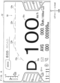
- Fig. 3 is a diagram illustrating a display image example in the display device 50.
- Fig. 3 is a diagram for explaining an example of a shape and a layout of the display image and does not necessarily illustrate an actual display example in the display device 50.
- the display device 50 includes a display screen 52.
- a boost information image 56 is displayed on the display screen 52.
- a vehicle information image 54 displayed with no relation to the boost state is also displayed in the display device 50.
- the vehicle information image 54 is an image indicating vehicle state information indicating a vehicle state of the automatic two-wheel vehicle 10.
- the vehicle information image 54 includes a speed information image 55a, a gear information image 55b, a battery remaining amount image 55c, a battery temperature image 55d, an auxiliary travel information image 55e, a time image 55f, a setting image 55g, a connection information image 55h, and a travel mode image 55i.
- the speed information image 55a is an image indicating a travel speed of the automatic two-wheel vehicle 10.
- the gear information image 55b is an image indicating a state of the gear of the automatic two-wheel vehicle 10. For example, a display of "D" of the speed information image 55a indicates a drive state.
- the speed information image 55a displays the number of shift transmission stages.
- the battery remaining amount image 55c is an image indicating a remaining amount of the battery 48.
- the plurality of battery remaining amount images 55c can indicate a remaining amount of each battery 48 in a case where the plurality of batteries 48 are provided.
- the battery temperature image 55d is an image indicating a temperature of the battery 48.
- the auxiliary travel information image 55e is an image indicating an average electricity cost, an average electricity cost, and an accumulated travel distance, for example.
- the time image 55f is an image indicating a current time
- a setting image 55g is an image indicating that a setting is being performed by a switch which is separately provided
- a connection information image 55h is an image indicating connection information of a mobile terminal device such as a smartphone connected to the automatic two-wheel vehicle 10.
- the travel mode image 55i is an image indicating whether the mode is a power saving travel mode limiting output of the travel power source 30 to be appropriate for power saving or a sport mode canceling the output limitation for power saving.
- the boost mode may be set in only the sport mode, or may set in both the power saving travel mode and the sport mode.
- the speed information image 55a is large and noticeably located in a region close to a right side in an intermediate region in the up-down direction.
- the gear information image 55b is located on a left side of the speed information image 55a.
- the speed information image 55a and the gear information image 55b are located away from each other on right and left sides.
- Two battery remaining amount images 55c are located on left and right sides of the speed information image 55a and the gear information image 55b.
- the travel mode image 55i is located on an upper side of the speed information image 55a and the gear information image 55b.
- the travel mode image 55i is located away from the speed information image 55a and the gear information image 55b in the up-down direction.
- the battery temperature image 55d is located on a left side of the travel mode image 55i and an upper side of the battery remaining amount image 55c on a right side.
- the auxiliary travel information image 55e is located on a lower side of the speed information image 55a, and the time image 55f, the setting image 55g, and the connection information image 55h are located on a lower side of the battery remaining amount image 55c and the gear information image 55b on the left side.
- the boost information image 56 includes a boost limitation condition information image 57.
- the boost limitation condition information image 57 passes between the speed information image 55a and the travel mode image 55i and extends from a position surrounding the gear information image 55b from right and upper sides to a right side to reach an upper side of the battery remaining amount image 55c on the right side.
- the boost information image 56 includes a boost permission display image 58.
- the boost permission display image 58 is an image indicating that the mode can be set to the boost mode.
- the boost permission display image 58 is character information of "e-boost".
- the boost permission display image 58 is not limited to the character information, but may be a pictogram code, a pattern, or a diagram indicating that the mode can be set to the boost mode.
- the boost permission display image 58 is located between the speed information image 55a and the boost limitation condition information image 57. An upper part of the boost permission display image 58 is overlapped with a lower part of the boost limitation condition information image 57.
- a part of the boost permission display image 58 is overlapped with a part of the boost limitation condition information image 57, thus information provided by the boost permission display image 58 and the boost limitation condition information image 57 is visually recognized with a small movement of vision.
- a remaining part of the boost permission display image 58 is not overlapped with the boost limitation condition information image 57, and a remaining part of the boost limitation condition information image 57 is not overlapped with the boost permission display image 58.
- information indicated by each of the boost permission display image 58 and the boost limitation condition information image 57 is easily grasped.
- the boost limitation condition information image 57 is an image indicating boost limitation condition information.
- the boost limitation condition is a condition to be limited in the boost traveling. As described above, the boost traveling is a travel mode temporarily allowed, thus a limitation may be applied to suppress an unexpected large load applied to the travel part.
- the boost limitation condition is a limitation to be a condition in the boost traveling.
- the boost limitation condition may be a condition which can suppress an unexpected load to the travel part, or may also be a limitation condition other than load suppression.
- the boost limitation condition are a boost remaining amount indicating a degree of the boost traveling which can be performed and a boostable output amount indicating a type of output by which the boost traveling can be performed, for example.
- the boost remaining amount relates to a remaining time for which the boost traveling can be continued in the boost traveling.
- the boost remaining amount relates to a remaining time for which the boost traveling can be continued in a case of being switched to the boost traveling in the normal traveling.
- a condition indicating whether or not the boost can be performed may be included as a boost limitation condition.
- the boost remaining amount is assumed to be expressed by an area increasing or decreasing as the boost traveling is continued, for example. An example of the boost remaining amount is described.
- the boost remaining amount as an example of the boost limitation condition may be a time for which the boost traveling can be performed. More specifically, the boost limitation condition may be a time equal to or shorter than n seconds.
- An upper limit value of n can be theoretically, experimentally, and empirically set in consideration of the load on the travel part. n gradually decreases in accordance with the continuous boost traveling.
- the boost remaining amount as an example of the boost limitation condition may be a power amount or a current amount which can be consumed by the boost traveling.
- a maximum value of the power amount or the current amount which can be consumed by the boost traveling can be theoretically, experimentally, and empirically set in consideration of the load on the travel part.
- the power amount or the current amount by the boost traveling is integrated based on an output from a sensor in the boost traveling.
- applicable as the power amount or the current amount which can be consumed in the boost traveling is a value subtracting an integrated value of the power amount or the current amount from the maximum value of the power amount or the current amount.
- the boost remaining amount as the boost limitation condition may be a difference in temperature which can be increased by the boost traveling.
- a maximum value of the temperature which can be increased by the boost traveling is theoretically, experimentally, and empirically set in consideration of the load on the travel part.
- a detection value of the temperature of the travel power source 30, the travel drive circuit 34, or the battery 48 is obtained based on a sensor output in the boost traveling.
- the difference in temperature which can be increased in the boost traveling may be a value obtained by subtracting the detection value of the temperature from a maximum value of the temperature.
- the boost remaining amount as the boost limitation condition may be a remaining amount calculated by plural combination of the time, the consumed power amount, consumed current amount, and the temperature described above.
- the description hereinafter is based on an assumption that the boost remaining amount is a time for which the boost traveling can be performed.
- the boostable output amount is the limitation as the condition in the boost traveling as described above.
- the boost traveling is allowed from a viewpoint of the load on the travel part, however, boost in which an output is limited is preferable to normal boost from the other viewpoint.
- the other viewpoint is a case where the remaining amount of the battery 48 is equal to or smaller than a preset value, for example.
- the boost traveling with a maximum output ma is allowed in the normal boost traveling, however, when the remaining amount of the battery 48 falls under a predetermined limitation state, an output limitation boost traveling with a maximum output mb smaller than ma is allowed.
- the boostable output amount indicates a boostable amount in each point of time expressed by an output value, for example, and the boost remaining amount indicates a degree of remaining boost which can be performed from each point of time expressed by a time, a consumed amount, or an amount of increasable temperature, for example.
- the boost remaining amount and the boostable output amount are assumed as the boost limitation condition.
- the control device 61 controls the display of the display device 50 to change a display area of the boost limitation condition information image 57 in accordance with the limitation condition in the boost traveling.
- the control device 61 controls the display of the display device 50 so that the display area of the boost limitation condition information image 57 is increased as the boost limitation condition is eased.
- a state where the limitation condition is eased indicates that a limitation on the boost traveling is eased, that is, for example, a limitation of a time, an output, a temperature, or a consumed amount limiting the boost is eased.
- increase in the boost remaining amount indicates that the limitation condition is eased.
- Increase in the boostable output amount indicates that the limitation condition is eased.
- the state where the boost limitation condition is eased indicates a state where a remaining amount of energy which can be continuously output in the boost traveling is large.
- the boost limitation condition information image 57 includes a plurality of segmented regions 57a, 57b, 57c, 57d, 57e, 57f, 57g, 57h, 57i, and 57j (simply referred to as the segmented region 57a etc. collectively in some cases hereinafter).
- the plurality of segmented regions 57a etc. are arranged in a row from a position on an upper side of the gear information image 55b toward a position on an upper side of the battery remaining amount image 55c on the right side.
- the display region of the boost limitation condition information image 57 is divided into the segmented regions 57a etc. described above, and a blank space sectioning the segmented regions 57a etc. adjacent to each other is displayed.
- the plurality of segmented regions 57a, 57b, and 57b close to one end are arranged to be directed upward from the gear information image 55b toward the right side.
- the remaining plurality of segmented regions 57d, 57e, 57f, 57g, 57h, 57i, and 57j are arranged along the right-left direction also in a position above the speed information image 55a.
- the plurality of segmented regions 57a etc. surround a part of the speed information image 55a.
- the plurality of segmented regions 57a etc. surround a part of the speed information image 55a close to an upper side and an upper left side.
- the segmented region 57a located in any one of ends (herein, a leftmost end) of the plurality of segmented regions 57a is an initial segmented display region 57a displayed firstly when the boost can be performed.
- the initial segmented display region 57a is a region finally entering a non-display state from a display state in the boost traveling.
- the initial segmented display region 57a described above has a largest display area in the plurality of segmented regions 57a etc.
- An area of each of the plurality of segmented regions 57a 57b, 57c, and 57c close to the initial segmented display region 57a in the segmented regions 57a increases toward a left end. Accordingly, the display area of the segmented regions 57a, 57b, 57c, and 57d indicating the boost remaining amount can be increased in an initial state where the boost can be performed or a late state where the boost amount decreases, and the boost remaining amount can be easily recognized. Particularly, the display area of the initial segmented display region 57a is largest, thus it is easily recognized that the boost can be performed even in a state where there is a small boost remaining amount.
- an area of each of the remaining plurality of segmented regions 57e, 57f, 57g, 57h, 57i, and 57j is not changed in the segmented regions 57a etc. however, this configuration is not necessary.
- the initial segmented display region 57a is a region bended into an L-like shape.
- the region bended into the L-like shape includes not only a case where a straight first region and a straight second region are perpendicular to each other but also a case where the first region and the second region are curved, a case where the first region and the second region intersect with each other at an angle other than 90 degrees, and a case where the first region and the second region are curved and intersect with each other. That is to say, the region bended into the L-like shape includes a case where an elongated region having directionality intersects without being continuously formed straight.
- the initial segmented display region 57a is located adjacent to the gear information image 55b. Furthermore specifically, included are a first region 57a1 extending in a horizontal direction on an upper side of the gear information image 55b and a second region 57a2 extending in an up-down direction on a right side of the gear information image 55b. The second region 57a2 extends downward from a right end of the first region 57a1. Accordingly, the initial segmented display region 57a surrounds a part of the gear information image 55b on a right side and close to an upper right side.
- the plurality of segmented regions 57e, 57f, 57g, 57h, 57i, and 57j are formed into shapes in which two parallelograms face each other.
- the plurality of segmented regions 57b, 57c, and 57d have shapes in which two quadrangular regions are combined with each other, and are formed into a shape sequentially close to the shape of the segmented region 57e from the shape of the initial segmented display region 57a.
- the plurality of segmented regions 57b, 57c, 57d, 57e, 57f, 57g, 57h, 57i, and 57j also include the first region and the second region.
- the first region of the subsequent segmented region 57b etc. is located on an upper side of the second region of the subsequent segmented region 57b etc.
- the first region of the subsequent segmented region 57b etc. is arranged in a row together with the first region 57a1 described above.
- the second region of the subsequent segmented region 57b etc. is arranged in a row together with the second region 57a2 described above.
- the control device 61 increases the number of displays of the plurality of segmented regions 57a etc. as the boost remaining amount is large. In other words, the display area is increased as the boost remaining amount is large.
- the display indicates that the image can be visually recognized in a state before the display.
- change of a color phase, color saturation, or brightness of a plain region is an example of the display.
- change of a white-ground region to a gray region, a black-ground region, or a chromatic color region is an example of the display.
- change of a black-ground region to a gray region, a white-ground region, or a chromatic color region is an example of the display.
- a region color before the display is preferably the same as a background color or a color closer to a background color than a region color after the display.
- Fig. 4 is a diagram illustrating a display example of the display device 50 in the boost mode state.
- Fig. 4 illustrates a state where the boost remaining amount has an upper limit value in the boost mode.
- a boostable time is assumed to be a maximum time.
- the display area of the boost limitation condition information image 57 is maximum, that is to say, all of the segmented regions 57a etc. are in the display state.
- the boost remaining amount decreases.
- a boostable time is assumed to decrease.
- a speed of decrease in the boost remaining amount may be changed in accordance with a consumption amount of energy in the boost traveling.
- the number of displays of the segmented region 57a etc. decreases in accordance with decrease in the boost remaining amount.
- the segmented regions 57a etc. sequentially enter a non-display state from right.
- the driver visually recognizes the number of displays of the segmented region 57a etc., that is a total area of the displayed segmented region, thereby being able to grasp the boost remaining amount such as a remaining time in which the boost traveling can be performed, for example.
- Each of the segmented regions 57a etc. may express an amount in which a maximum boost remaining amount is equally divided or an amount in which a maximum boost remaining amount is non-equally divided.
- the boost traveling When the boost traveling is continued, the boost remaining amount becomes 0, and the display area of the boost limitation condition information image 57 is minimized, or none of the segmented regions 57a etc. is displayed as illustrated in Fig. 6 . Accordingly, control of switching the mode from the boost travel mode to the normal travel mode is performed.
- the driver confirms the display, thereby being able to recognize that a time in which the boost travel can be performed becomes 0, for example. That is to say, the display area of the boost limitation condition information image 57 is also considered to have a size corresponding to the number of countdowns of a time after starting the boost traveling.
- a memory image 57m corresponding to the boost remaining amount may be displayed in the boost limitation condition information image 57.
- the memory image 57m may be displayed regardless of presence or absence of the display of the segmented region 57a etc., or may also be displayed in a region which does not include the display of the segmented region 57a etc.
- the memory image 57m is displayed in a region in a non-display state in the segmented region 57a etc.
- Each memory image 57m corresponds to each segmented region 57a etc.
- Each memory image 57m extends along a boundary between the first region and the second region in each segmented region 57a etc. The driver visually recognizes the memory image 57m, thereby being able to grasp a ratio of a current boost remaining amount to a maximum boost remaining amount.
- the boost limitation condition information image 57 is displayed in the display device 50 not only in the boost mode but also a boost standby state before the boost switch 44 is pressed.
- the control device 61 changes the display form of the boost limitation condition information image 57 in the boost information image 56 between the boost mode state and the boost standby state.
- the boost standby state indicates one state of the normal travel mode. A state where the boost remaining amount remains in the normal travel mode (that is to say, a state where boost is not performed) is the boost standby state.
- Fig. 7 is a diagram illustrating a display example in the display device 50 in the boost standby state.
- Fig. 7 illustrates a display example in the normal travel mode.
- the boost traveling and the boost mode are assumed to be canceled when the boost remaining amount becomes zero by the boost traveling.
- the boost traveling can be performed.
- the boost limitation condition is eased and the boost remaining amount increases by continuing the normal travel mode.
- the mode enters the boost standby state, and the boost limitation condition information image 57 is displayed in the display device 50.
- the boost standby state indicates a state switchable to the boost traveling and a state allowing the boost traveling in the normal travel mode.
- the display form of the boost limitation condition information image 57 is different between the boost mode state and the boost standby state to clearly display the boost standby state for the driver.
- a region color of the segmented region 57a etc. in the boost standby state is different from a background color, but is close to the background color compared with a region color of the segmented region 57a etc. in the boost mode state.
- a region color of the segmented region 57a etc. in the boost standby state is an achromatic color
- a region color of the segmented region 57a etc. in the boost mode state is a chromatic color.
- the segmented region 57a etc. in the boost mode state is more noticeable than that in the boost standby state.
- the state where the display form of the boost limitation condition information image 57 is changed between the boost mode state and the boost standby state may indicate any of a case where a color phase, color saturation, or brightness of the boost limitation condition information image 57 is changed and a case where a pattern or a shape of the boost limitation condition information image 57 is changed.
- the control device 61 controls the display of the display device 50 so that the display area of the boost limitation condition information image 57 is large as the boostable output amount is large.
- each of the plurality of segmented regions 57a etc. includes the first region and the second region as described above.
- the display area of the plurality of segmented regions 57a etc. is changed in accordance with the boostable output amount.
- both the first region and the second region are displayed in each of the plurality of segmented regions 57a etc. in the normal boost state where the boost traveling with the maximum output ma is allowed.
- a state where the state falls under a predetermined limitation state and the output limitation boost traveling with the maximum output mb smaller than ma is allowed, one of the first region and the second region is assumed to be displayed in each of the plurality of segmented regions 57a etc. as illustrated in Fig. 9.
- Fig. 9 illustrates an example of displaying the first region on the upper side.
- the boost information image 56 includes the boost permission display image 58 as described above.
- the boost permission display image 58 is an image displaying that the boost traveling can be performed.
- the control device 61 explicitly displays the boost permission display image 58 in the display device 50 so that the boost permission display image 58 can be recognized.
- the explicit display indicates that a state where the boost can be performed, which is meant by the boost permission display image 58, is displayed so that the driver can recognize the state. For example, when the boost permission display image 58 enters a recognizable state from a non-recognizable state, it is assumed that a difference of brightness between the background color and the boost permission display image 58 increases or a color of the boost permission display image 58 is changed from an achromatic color to a chromatic color.
- Fig. 10 is a flow chart illustrating a display processing example by the control device 61.
- the present processing is executed as a parallel or pseudo-parallel processing with processing performed by the control device 61 for traveling of the automatic two-wheel vehicle 10.
- Step S1 the control device 61 determines whether the start switch 46 is turned on. Processing of Step S1 is repeated until the driver turns on the start switch 46. When it is determined that the start switch 46 is turned on, processing proceeds to Step S2.
- Step S2 the boost output limitation state is determined.
- the boost output limitation state is determined based on the output of a battery remaining amount sensor 69a, for example. For example, it is assumed that a first reference value and a second reference value larger than the first reference value are previously set. It is determined that the boost cannot be performed when the battery remaining amount is smaller than the predetermined first reference value. It is determined that the output limitation boost can be performed when the battery remaining amount is larger than the first reference value and smaller than the second reference value. It is determined that the boost can be performed when the battery remaining amount is larger than the second reference value.
- the boost cannot be performed in accordance with the other condition. For example, when a temperature of the battery 48 or the travel power source 30 is high, when an operation defect thereof is detected, or when a defect of output current is detected in the travel drive circuit 34, for example, it may be determined that the boost cannot be performed.
- the boost output limitation state may be determined additionally based on the other state of the travel part.
- the boost output limitation state may be determined additionally based on a temperature of the battery 48 or a temperature of the travel power source 30.
- Step S2 the process proceeds to Step S3 when it is determined that the boost cannot be performed, the process proceeds to Step S11 when it is determined that the output limitation boost can be performed, and the process proceeds to Step S21 when it is determined that the boost can be performed.
- Step S3 the boost limitation condition information image 57 and the boost permission display image 58 enter an off state (refer to Fig. 6 ). Accordingly, the driver can recognize that the boost mode cannot be set. Note that the mode does not make a transition to the boost mode even when the driver operates the boost button in such a state.
- Step S4 it is determined whether the start switch 46 is turned off. When it is determined that the start switch 46 is turned off, the process is finished, and when it is determined that the start switch 46 is not turned off, the process returns to Step S2 to repeat the process subsequent to the determination of the boost output limitation state.
- Step S21 the boost standby state is displayed.
- the plurality of segmented regions 57a etc. are displayed in accordance with the boost remaining amount (refer to Fig. 8 ).
- the boost permission display image 58 is displayed. All of the plurality of segmented regions 57a etc. are not displayed in some cases depending on a state of the travel part or when a lapse time after a previous boost traveling is short.
- Step S22 it is determined whether or not the boost mode enters an on state based on the output of the boost switch 44.
- the process proceeds to Step S23.
- the boost switch 44 is not operated and it is determined that the boost mode is kept in an off state, the process proceeds to Step S4.
- Step S23 the display form of the boost limitation condition information image 57 is changed to the display form for the boost mode state (refer to Fig. 4 ).
- a region color of the segmented region 57a etc. of the boost limitation condition information image 57 is changed to a color away from a background color. Accordingly, the driver easily recognizes the boost mode.
- the number of displays of the plurality of segmented regions 57a etc. increases in some cases. For example, there is a case where some of the plurality of segmented regions 57a etc. is initially displayed in a case where a lapse time after a previous boost traveling is short, and the number of displays of the plurality of segmented regions 57a etc. gradually increases as a time in which the boost traveling is not performed increases subsequently. That is to say, there is a case where a time in which the boost traveling is not performed is counted up and the number of displays of the plurality of segmented regions 57a increases in accordance with the counted time.
- Step S24 it is determined whether or not the throttle 42a is turned on. The process proceeds to Step S25 when it is determined that the throttle 42a is turned on, and the process proceeds to Step S27 when it is determined that the throttle 42a is not turned on.
- the area change condition is a condition reducing the area of the boost limitation condition information image 57, and is a condition reducing the number of displays of the segmented regions 57a etc. herein.
- the area change condition indicates whether or not a time in which the throttle 42a is an on state has elapsed for which the number of displays of the segmented regions 57a should be reduced.
- the maximum time, in which the boost traveling can be performed indicating the boost remaining amount is 20 seconds
- each of the segmented regions 57a etc. indicates the boost travel time of two seconds
- a condition reducing the number of displays of the segmented regions 57a etc. every two seconds for which the throttle 42a is the on state is satisfied.
- Step S25 When it is determined that the area change condition is satisfied in Step S25, the process proceeds to Step S26, and when it is determined that the area change condition is not satisfied, the process proceeds to Step S27.
- the area of the boost limitation condition information image 57 is reduced in Step S26.
- the number of displays of the segmented regions 57a etc. is reduced herein. The process then proceeds to Step S27.
- Step S27 when it is determined that the throttle 42a is not in the on state in the next Step S24, when it is determined that the area change condition is not satisfied in Step S25, and after the process of Step S26 is performed.
- Step S27 it is determined whether or not a boost off condition is satisfied.
- the boost off condition is a condition for turning off the boost mode.
- the boost off condition indicates that a predetermined first time has elapsed after the boost mode is set in Step S22 and the operation has not been performed on the throttle 42a, for example.
- the boost off condition indicates that the operation on the throttle 42a is continued and the boost traveling state is continued for a predetermined second time.
- the boost off condition indicates that the operation on the throttle 42a is stopped, for example.
- the process returns to Step S25 when it is determined that any of these conditions is satisfied, and the process proceeds to Step S4 when it is determined that any of them is satisfied.
- Step S11 When it is determined that the output limitation boost can be performed in Step S2, the process proceeds to Step S11.
- the process from Steps S11 to S17 is similar to that from Steps S21 to S27.
- the process from Steps S11 to S17 is the process in the output limitation boostable state, thus the first region of the segmented region 57a etc. is displayed, and the second region is not displayed in Steps S11, S13, and S16.
- control so that the boost travel mode makes a transition to the normal travel mode after a predetermined time has elapsed even when the boost operation is performed (refer to the description regarding Step S17 which is the process similar to that in Step S27).
- the display area of the boost limitation condition information image 57 is changed in accordance with the limitation condition in the boost traveling.
- the driver visually recognizes the display area of the boost limitation condition information image 57, thereby being able to clearly recognize the limitation condition on the boost traveling.
- the driver can intuitively grasp a degree of the boost limitation condition from a size of the display area of the image 57, and can easily grasp the boost limitation condition from increase and decrease in the display area of the image 57 compared with a case where the boost limitation condition is displayed by numerical value information.
- the display area of the boost limitation condition information image 57 is large as the limitation condition in the boost traveling is eased.
- the limitation condition in the boost traveling is eased as the display area of the boost limitation condition information image 57 is large.
- the display area of the boost limitation condition information image 57 is large as the boost remaining amount is large.
- the boost remaining amount is large as the display area of the boost limitation condition information image 57 is large.
- the boost remaining amount which may be changed before the boost traveling or in the boost traveling can be clearly displayed by increase and decrease in the display area of the boost limitation condition information image 57.
- a magnitude of the boost remaining amount and a magnitude of the display area of the boost limitation condition information image 57 have a positive correlationship, thus the magnitude of the boost remaining amount can be intuitively grasped from the display area of the boost limitation condition information image 57.
- the number of displays of the segmented regions 57a etc. is increased as the boost remaining amount is large, thus the boost remaining amount is grasped in accordance with the number of displays of the segmented regions 57a etc.
- the initial segmented display region 57a is the region bended into the L-like shape, thus the other vehicle information image 54 in the display device 50 can be displayed on an inner side of the region bended into the L-like shape.
- the initial segmented display region 57a is disposed near the vehicle information image 54, thus it is easily recognized that the boost can be performed.
- the initial segmented display region 57a is the region bended into the L-like shape, thus the area of the initial segmented display region 57a can be easily increased. Also from this viewpoint, it is easily recognized that the boost can be performed.
- the initial segmented display region 57a has the largest display area in the segmented regions 57a etc., thus it is easily recognized that the boost can be performed.
- the display area of the boost limitation condition information image 57 is large as the boostable output amount is large.
- the boostable output amount can be clearly displayed by the size of the display area of the boost limitation condition information image 57 before the boost traveling or in the boost traveling.
- the number of displays of the segmented regions 57a etc. is changed in accordance with the boost remaining amount, and the display area of each of the segmented regions 57a etc. is changed in accordance with the boostable output amount. Accordingly, the boost remaining amount is grasped by the number of displays of the segmented regions 57a etc., the boostable output amount is grasped by the display area of each segmented region 57a etc., and both the boost remaining amount and the boostable output amount are easily expressed.
- the boost information image 56 includes the boost permission display image 58, and when it is determined that the boost traveling can be performed, the boost permission display image 58 is explicitly displayed in the display device 50 so that the boost permission display image 58 can be recognized.
- the driver recognizes the boost permission display image 58, thereby being able to easily recognize that the boost traveling can be performed.
- the gear information image 55b as the example of the vehicle information image 54 is located adjacent to the initial segmented display region 57a. It is considered that the driver often focuses on the gear information image 55b as the example of the vehicle information image 54.
- the initial segmented display region 57a is located adjacent to the gear information image 55b, thus it is easily recognized that the boost can be performed.
- the vehicle information image displayed adjacent to the initial segmented display region 57a may not be the gear information image 55b, but may be the battery remaining amount image 55c or the battery temperature image 55d, for example.
- the vehicle information image may be information indicating the hybrid automobile is in a state of hybrid traveling or traveling by an electrical motor.
- the vehicle information image may be an image indicating switching information of switching between AT and MT.
- the display form of the boost information image 56 is changed between the boost mode state and the boost standby state.
- the display form of the boost limitation condition information image 57 is changed.
- it can be grasped whether the mode is the boost mode state or the boost standby state by the display form of the boost limitation condition information image 57.
- the display device 50 may have a different display mode in accordance with ambient brightness. For example, brightness of a background in a dark environment such as nighttime may be lower than that in a bright environment such as daytime. In this case, it is sufficient that the brightness is changed for each background of the image displayed in the background to noticeably display the image in each background, for example. Accordingly, display contents of the display device 50 is visually recognized easily in accordance with ambient brightness.
- the description in the above embodiment is based on the assumption that the travel power source 30 is mainly the example of the electrical motor.
- the display system and the display method described in the embodiment are also applicable to a vehicle including and internal combustion engine in place of or in addition to the electrical motor.
- the display system can include not only the hybrid vehicle but also a vehicle having an electrical motor as a single drive source and a vehicle having an internal combustion engine as a single drive source.
- the display system can also be applied to a power-assisted bicycle or a vehicle having three or more wheels in addition to the automatic two-wheel vehicle.
- the display system can also be applied to a vehicle with a shifter including a gearbox.
- an increase amount of output in the boost traveling is preferably handled by increase in output by the electrical motor.
- increase in exhaust gas according to the increase in output can be suppressed.
- the increase amount of output in the boost traveling is not limited to the increase in output by the electrical motor, however, the present embodiment also includes a case of applying an internal combustion engine together or increasing output by a single internal combustion engine.
- a rotation number information image 155 indicating the number of rotations of a power engine in a bar form may be displayed on the display screen 52 of the display device 50 as illustrated in Fig. 11 .
- expression of the number of rotations of the power engine by the bar form indicates expression of the number of rotations of the power engine by a length of a rod-like display region.
- the rotation number information image 155 gets longer as the number of rotations of the power engine increases.
- the rotation number information image 155 extends along a right-left direction in a position on an upper side of the boost limitation condition information image 57.
- the rotation number information image 155 is arranged in parallel to the segmented regions 57d, 57e, 57f, 57g, 57h, 57i, and 57j.
- a left end of the rotation number information image 155 corresponds to a rotation number 0 and a right end thereof corresponds to a maximum rotation number.
- the rotation number information image 155 increases in length in a right direction by increase in the number of rotations of the power engine based on the left end.
- a direction in which the length of the rotation number information image 155 increases by the increase in the number of rotations and a direction in which a display length of the segmented region 57a etc. increases by reduction in the limitation condition in the boost traveling coincide with each other.
- the reduction in the limitation condition in the boost traveling indicates that the limitation is eased and the boost remaining amount increases.
- a pattern of increase and decrease in the display area of the rotation number information image 155 is similar to that of the boost limitation condition information image 57, thus the driver easily grasps the reduction in the limitation condition in the boost traveling.
- the boost limitation condition information image 57 is located between the speed information image 55a and the rotation number information image 155, thus the driver sees the boost limitation condition information image 57 while confirming the speed and the number of rotations, thereby easily grasping the limitation condition.
- the boost limitation condition information image 57 is displayed in the display device 50 displaying the vehicle information image 54 including the speed information image 55a.
- the boost limitation condition information image 57 may be displayed in the other display device different from the display device 50 displaying the vehicle information image 54 including the speed information image 55a, for example.
- the boost limitation condition information image 57 may be displayed in a display device of a mobile terminal device such as a smartphone.
- a processing function of changing the display area of the boost limitation condition information image may be achieved by a control part of the mobile terminal device or a control part included in the vehicle.
- a program for the control part of the mobile terminal device to perform display control of the display device may be provided in a form of an application program.
- the display area of the boost limitation condition information image 57 may increase or decrease in a smaller or larger unit.
- the display area of the boost limitation condition information image 57 may increase or decrease in a unit of display pixel of the display device 50.
- the boost limitation condition is set in consideration of a thermal load and a mechanical load on a part operated in traveling.
- the boost limitation condition may be set in consideration of the other factor as the other embodiment.
- the boost limitation condition may be set in consideration of a factor regarding operability of a driver, a factor regarding a traffic regulation, and a factor regarding an ambient environment such as a type of a travel route, a state of a road surface, weather, and an environment temperature.
- the boost limitation condition may be changed based on a vehicle state such as a gear ratio or a vehicle speed.
- the boost permission display image 58 may be omitted. When a defect occurs in the travel power source 30, there may be a case where the boost is not allowed and the boost permission display image 58 and the boost limitation condition information image 57 are not displayed.
- the area of the boost limitation condition information image 57 may increase or decrease contrary to the case in the description in the above embodiment. That is to say, also applicable as the other embodiment is a case where the display is performed so that the display area decreases as the remaining amount increases and the display area increases as the remaining amount decreases.
- the boost limitation condition information image 57 is a horizontally long meter display form.
- the area is changed in a lateral direction, thus an area change amount can be easily increased.
- the display area is preferably changed in a direction along a longitudinal direction of the boost limitation condition information image 57 in the meter display form.
- a change of an area in a vertical direction is applicable instead of the change of the area in the lateral direction, and also applicable as the other embodiment is an example that the area of the boost limitation condition information image is changed in the other direction in addition to or in place of the change of the area thereof in the vertical or lateral direction.
- a vehicle body is operated by a weight shift of the driver in some cases.
- a position of the driver with respect to the display device 50 is changed, thus visibility of the display device 50 with respect to the driver decreases in some cases.
- the boost limitation condition is displayed based on the area of the display region as with the present embodiment, thus decrease in visibility of the boost limitation condition for the driver can be suppressed even when the position of the driver with respect to the display device 50 is changed by the weight shift of the driver.
- the saddle-riding vehicle is not provided with a roof covering the driver in many cases. In this case, solar light is reflected by a meter, thus visibility of display contents decreases in some cases.
- the boost limitation condition is displayed based on the area of the display region as with the present embodiment, thus decrease in visibility of the limitation condition for the driver can be suppressed.
- circuitry or processing circuitry which includes general purpose processors, special purpose processors, integrated circuits, ASICs ("Application Specific Integrated Circuits"), conventional circuitry and/or combinations thereof which are configured or programmed to perform the disclosed functionality.
- Processors are considered processing circuitry or circuitry as they include transistors and other circuitry therein.
- the circuitry, units, or means are hardware that carry out or are programmed to perform the recited functionality.
- the hardware may be any hardware disclosed herein or otherwise known which is programmed or configured to carry out the recited functionality.
- the hardware is a processor which may be considered a type of circuitry
- the circuitry, means, or units are a combination of hardware and software, the software being used to configure the hardware and/or processor.
Landscapes
- Engineering & Computer Science (AREA)
- Chemical & Material Sciences (AREA)
- Combustion & Propulsion (AREA)
- Transportation (AREA)
- Mechanical Engineering (AREA)
- Instrument Panels (AREA)
Applications Claiming Priority (1)
| Application Number | Priority Date | Filing Date | Title |
|---|---|---|---|
| JP2022160499A JP2024053958A (ja) | 2022-10-04 | 2022-10-04 | 乗物用の表示システム、鞍乗型乗物及び乗物用の表示方法 |
Publications (2)
| Publication Number | Publication Date |
|---|---|
| EP4349632A1 EP4349632A1 (en) | 2024-04-10 |
| EP4349632B1 true EP4349632B1 (en) | 2025-05-14 |
Family
ID=88146874
Family Applications (1)
| Application Number | Title | Priority Date | Filing Date |
|---|---|---|---|
| EP23198854.4A Active EP4349632B1 (en) | 2022-10-04 | 2023-09-21 | Display system for vehicle, saddle-riding vehicle, and display method for vehicle |
Country Status (3)
| Country | Link |
|---|---|
| US (1) | US20240109417A1 (enExample) |
| EP (1) | EP4349632B1 (enExample) |
| JP (1) | JP2024053958A (enExample) |
Families Citing this family (3)
| Publication number | Priority date | Publication date | Assignee | Title |
|---|---|---|---|---|
| KR20230148869A (ko) * | 2022-04-18 | 2023-10-26 | 현대자동차주식회사 | 차량의 부스트 모드 제어 방법 |
| KR20230149356A (ko) * | 2022-04-19 | 2023-10-27 | 현대자동차주식회사 | 차량의 부스트 모드 제어 방법 |
| US20240208338A1 (en) * | 2022-12-21 | 2024-06-27 | Brp-Rotax Gmbh & Co. Kg | Boost system for an electric vehicle, electric vehicle having same, and method for boosting a speed of an electric vehicle |
Family Cites Families (11)
| Publication number | Priority date | Publication date | Assignee | Title |
|---|---|---|---|---|
| JPS59189676U (ja) * | 1983-06-01 | 1984-12-15 | カルソニックカンセイ株式会社 | バ−グラフ表示装置 |
| JPH0513829U (ja) * | 1991-08-06 | 1993-02-23 | 株式会社カンセイ | 発光表示装置 |
| JP2002331856A (ja) * | 2001-05-08 | 2002-11-19 | Blitz:Kk | レーシングブーストメータ |
| DE102010010443A1 (de) * | 2010-02-25 | 2011-08-25 | Dr. Ing. h.c. F. Porsche Aktiengesellschaft, 70435 | Anzeigevorrichtung eines Kraftfahrzeugs |
| DE102010010446A1 (de) * | 2010-02-25 | 2011-08-25 | Dr. Ing. h.c. F. Porsche Aktiengesellschaft, 70435 | Anzeige- und Bediensystem eines Kraftfahrzeugs |
| DE102012000584A1 (de) * | 2012-01-13 | 2013-07-18 | Audi Ag | Vorrichtung zur Anzeige von Informationen in einem Hybridfahrzeug |
| US20140277877A1 (en) * | 2013-03-15 | 2014-09-18 | Deere & Company | Control and Operator Interface For Combine Having Hybrid Drive |
| JP6318706B2 (ja) * | 2014-03-04 | 2018-05-09 | 株式会社デンソー | 車両用表示装置 |
| JP7283478B2 (ja) * | 2018-07-10 | 2023-05-30 | 日本精機株式会社 | 車両用表示装置、車両用表示装置の制御方法、及び車両用表示装置の制御プログラム |
| US11186199B2 (en) * | 2019-11-22 | 2021-11-30 | Toyota Motor Engineering & Manufacturing North America, Inc. | HEV battery SOC meter and boost power display |
| US20230303214A1 (en) * | 2022-02-14 | 2023-09-28 | Taiga Motors Inc. | Electric vehicle |
-
2022
- 2022-10-04 JP JP2022160499A patent/JP2024053958A/ja active Pending
-
2023
- 2023-09-07 US US18/462,526 patent/US20240109417A1/en active Pending
- 2023-09-21 EP EP23198854.4A patent/EP4349632B1/en active Active
Also Published As
| Publication number | Publication date |
|---|---|
| EP4349632A1 (en) | 2024-04-10 |
| US20240109417A1 (en) | 2024-04-04 |
| JP2024053958A (ja) | 2024-04-16 |
Similar Documents
| Publication | Publication Date | Title |
|---|---|---|
| EP4349632B1 (en) | Display system for vehicle, saddle-riding vehicle, and display method for vehicle | |
| US10196004B2 (en) | Display device for saddle-type vehicle, and saddle-type vehicle | |
| JP6725377B2 (ja) | カメラモニターシステム | |
| US9377648B2 (en) | Liquid crystal display device comprising a warm-up configuration and a normal configuration, motorcycle including same, and method of using same | |
| US11295704B2 (en) | Display control device, display control method, and storage medium capable of performing appropriate luminance adjustment in case where abnormality of illuminance sensor is detected | |
| US12428094B2 (en) | Vehicle controller, vehicle including a vehicle controller, and method of operating a vehicle | |
| GB2548966A (en) | Parallel parking assistant | |
| JP2011098634A (ja) | ヘッドアップディスプレイ装置 | |
| US20150183481A1 (en) | Straddle type vehicle with liquid crystal display device | |
| EP4349633B1 (en) | Display system for vehicle, vehicle, and display method for vehicle | |
| EP3932728A1 (en) | Powertrain system for electric automobile, electric automobile and method of controlling electric automobile | |
| US10353396B2 (en) | Vehicle periphery monitoring device | |
| EP2868563B1 (en) | Electrically assisted bicycle | |
| US20210179086A1 (en) | Parking assisting device, parking assisting method and storage medium storing program for the parking assisting device | |
| EP2299095B1 (en) | Engine control system for a vehicle | |
| US12049135B2 (en) | Display device, display control method, and non-transitory computer-readable recording medium | |
| US20200398816A1 (en) | Hybrid Vehicle Control Method and Hybrid Vehicle Control Device | |
| KR101223406B1 (ko) | 차량 영상 실내 디스플레이 장치 및 이의 제어 방법 | |
| US20210043164A1 (en) | Display control device, display control method, and storage medium | |
| US12071125B2 (en) | Vehicle control apparatus | |
| US12387689B1 (en) | Systems and methods for dynamic dimming of a set of displays sharing a single energy source | |
| US20080258896A1 (en) | System for improving back end visibility and machine using same | |
| JP2017140983A (ja) | 車両用表示装置 | |
| CN216424546U (zh) | 助力系统和重载运输自卸车 | |
| EP4603350A1 (en) | Operation assist apparatus |
Legal Events
| Date | Code | Title | Description |
|---|---|---|---|
| PUAI | Public reference made under article 153(3) epc to a published international application that has entered the european phase |
Free format text: ORIGINAL CODE: 0009012 |
|
| STAA | Information on the status of an ep patent application or granted ep patent |
Free format text: STATUS: THE APPLICATION HAS BEEN PUBLISHED |
|
| AK | Designated contracting states |
Kind code of ref document: A1 Designated state(s): AL AT BE BG CH CY CZ DE DK EE ES FI FR GB GR HR HU IE IS IT LI LT LU LV MC ME MK MT NL NO PL PT RO RS SE SI SK SM TR |
|
| STAA | Information on the status of an ep patent application or granted ep patent |
Free format text: STATUS: REQUEST FOR EXAMINATION WAS MADE |
|
| 17P | Request for examination filed |
Effective date: 20241008 |
|
| RBV | Designated contracting states (corrected) |
Designated state(s): AL AT BE BG CH CY CZ DE DK EE ES FI FR GB GR HR HU IE IS IT LI LT LU LV MC ME MK MT NL NO PL PT RO RS SE SI SK SM TR |
|
| GRAP | Despatch of communication of intention to grant a patent |
Free format text: ORIGINAL CODE: EPIDOSNIGR1 |
|
| STAA | Information on the status of an ep patent application or granted ep patent |
Free format text: STATUS: GRANT OF PATENT IS INTENDED |
|
| RIC1 | Information provided on ipc code assigned before grant |
Ipc: B60K 35/22 20240101ALI20241128BHEP Ipc: B60K 35/21 20240101AFI20241128BHEP |
|
| INTG | Intention to grant announced |
Effective date: 20241212 |
|
| GRAS | Grant fee paid |
Free format text: ORIGINAL CODE: EPIDOSNIGR3 |
|
| GRAA | (expected) grant |
Free format text: ORIGINAL CODE: 0009210 |
|
| STAA | Information on the status of an ep patent application or granted ep patent |
Free format text: STATUS: THE PATENT HAS BEEN GRANTED |
|
| AK | Designated contracting states |
Kind code of ref document: B1 Designated state(s): AL AT BE BG CH CY CZ DE DK EE ES FI FR GB GR HR HU IE IS IT LI LT LU LV MC ME MK MT NL NO PL PT RO RS SE SI SK SM TR |
|
| REG | Reference to a national code |
Ref country code: GB Ref legal event code: FG4D |
|
| REG | Reference to a national code |
Ref country code: CH Ref legal event code: EP |
|
| REG | Reference to a national code |
Ref country code: IE Ref legal event code: FG4D |
|
| REG | Reference to a national code |
Ref country code: DE Ref legal event code: R096 Ref document number: 602023003480 Country of ref document: DE |
|
| REG | Reference to a national code |
Ref country code: NL Ref legal event code: MP Effective date: 20250514 |
|
| PG25 | Lapsed in a contracting state [announced via postgrant information from national office to epo] |
Ref country code: FI Free format text: LAPSE BECAUSE OF FAILURE TO SUBMIT A TRANSLATION OF THE DESCRIPTION OR TO PAY THE FEE WITHIN THE PRESCRIBED TIME-LIMIT Effective date: 20250514 Ref country code: PT Free format text: LAPSE BECAUSE OF FAILURE TO SUBMIT A TRANSLATION OF THE DESCRIPTION OR TO PAY THE FEE WITHIN THE PRESCRIBED TIME-LIMIT Effective date: 20250915 Ref country code: ES Free format text: LAPSE BECAUSE OF FAILURE TO SUBMIT A TRANSLATION OF THE DESCRIPTION OR TO PAY THE FEE WITHIN THE PRESCRIBED TIME-LIMIT Effective date: 20250514 |
|
| PGFP | Annual fee paid to national office [announced via postgrant information from national office to epo] |
Ref country code: DE Payment date: 20250929 Year of fee payment: 3 |
|
| REG | Reference to a national code |
Ref country code: LT Ref legal event code: MG9D |
|
| PG25 | Lapsed in a contracting state [announced via postgrant information from national office to epo] |
Ref country code: GR Free format text: LAPSE BECAUSE OF FAILURE TO SUBMIT A TRANSLATION OF THE DESCRIPTION OR TO PAY THE FEE WITHIN THE PRESCRIBED TIME-LIMIT Effective date: 20250815 Ref country code: NO Free format text: LAPSE BECAUSE OF FAILURE TO SUBMIT A TRANSLATION OF THE DESCRIPTION OR TO PAY THE FEE WITHIN THE PRESCRIBED TIME-LIMIT Effective date: 20250814 |
|
| PG25 | Lapsed in a contracting state [announced via postgrant information from national office to epo] |
Ref country code: NL Free format text: LAPSE BECAUSE OF FAILURE TO SUBMIT A TRANSLATION OF THE DESCRIPTION OR TO PAY THE FEE WITHIN THE PRESCRIBED TIME-LIMIT Effective date: 20250514 Ref country code: PL Free format text: LAPSE BECAUSE OF FAILURE TO SUBMIT A TRANSLATION OF THE DESCRIPTION OR TO PAY THE FEE WITHIN THE PRESCRIBED TIME-LIMIT Effective date: 20250514 |
|
| REG | Reference to a national code |
Ref country code: AT Ref legal event code: MK05 Ref document number: 1794522 Country of ref document: AT Kind code of ref document: T Effective date: 20250514 |
|
| PG25 | Lapsed in a contracting state [announced via postgrant information from national office to epo] |
Ref country code: BG Free format text: LAPSE BECAUSE OF FAILURE TO SUBMIT A TRANSLATION OF THE DESCRIPTION OR TO PAY THE FEE WITHIN THE PRESCRIBED TIME-LIMIT Effective date: 20250514 |
|
| PG25 | Lapsed in a contracting state [announced via postgrant information from national office to epo] |
Ref country code: HR Free format text: LAPSE BECAUSE OF FAILURE TO SUBMIT A TRANSLATION OF THE DESCRIPTION OR TO PAY THE FEE WITHIN THE PRESCRIBED TIME-LIMIT Effective date: 20250514 |
|
| PG25 | Lapsed in a contracting state [announced via postgrant information from national office to epo] |
Ref country code: AT Free format text: LAPSE BECAUSE OF FAILURE TO SUBMIT A TRANSLATION OF THE DESCRIPTION OR TO PAY THE FEE WITHIN THE PRESCRIBED TIME-LIMIT Effective date: 20250514 |
|
| PGFP | Annual fee paid to national office [announced via postgrant information from national office to epo] |
Ref country code: FR Payment date: 20250930 Year of fee payment: 3 |
|
| PG25 | Lapsed in a contracting state [announced via postgrant information from national office to epo] |
Ref country code: RS Free format text: LAPSE BECAUSE OF FAILURE TO SUBMIT A TRANSLATION OF THE DESCRIPTION OR TO PAY THE FEE WITHIN THE PRESCRIBED TIME-LIMIT Effective date: 20250814 |
|
| PG25 | Lapsed in a contracting state [announced via postgrant information from national office to epo] |
Ref country code: IS Free format text: LAPSE BECAUSE OF FAILURE TO SUBMIT A TRANSLATION OF THE DESCRIPTION OR TO PAY THE FEE WITHIN THE PRESCRIBED TIME-LIMIT Effective date: 20250914 |
|
| PG25 | Lapsed in a contracting state [announced via postgrant information from national office to epo] |
Ref country code: LV Free format text: LAPSE BECAUSE OF FAILURE TO SUBMIT A TRANSLATION OF THE DESCRIPTION OR TO PAY THE FEE WITHIN THE PRESCRIBED TIME-LIMIT Effective date: 20250514 |
|
| PG25 | Lapsed in a contracting state [announced via postgrant information from national office to epo] |
Ref country code: SM Free format text: LAPSE BECAUSE OF FAILURE TO SUBMIT A TRANSLATION OF THE DESCRIPTION OR TO PAY THE FEE WITHIN THE PRESCRIBED TIME-LIMIT Effective date: 20250514 Ref country code: DK Free format text: LAPSE BECAUSE OF FAILURE TO SUBMIT A TRANSLATION OF THE DESCRIPTION OR TO PAY THE FEE WITHIN THE PRESCRIBED TIME-LIMIT Effective date: 20250514 |
|
| PG25 | Lapsed in a contracting state [announced via postgrant information from national office to epo] |
Ref country code: CZ Free format text: LAPSE BECAUSE OF FAILURE TO SUBMIT A TRANSLATION OF THE DESCRIPTION OR TO PAY THE FEE WITHIN THE PRESCRIBED TIME-LIMIT Effective date: 20250514 |
|
| PG25 | Lapsed in a contracting state [announced via postgrant information from national office to epo] |
Ref country code: EE Free format text: LAPSE BECAUSE OF FAILURE TO SUBMIT A TRANSLATION OF THE DESCRIPTION OR TO PAY THE FEE WITHIN THE PRESCRIBED TIME-LIMIT Effective date: 20250514 |
|
| PG25 | Lapsed in a contracting state [announced via postgrant information from national office to epo] |
Ref country code: SK Free format text: LAPSE BECAUSE OF FAILURE TO SUBMIT A TRANSLATION OF THE DESCRIPTION OR TO PAY THE FEE WITHIN THE PRESCRIBED TIME-LIMIT Effective date: 20250514 |
|
| PG25 | Lapsed in a contracting state [announced via postgrant information from national office to epo] |
Ref country code: IT Free format text: LAPSE BECAUSE OF FAILURE TO SUBMIT A TRANSLATION OF THE DESCRIPTION OR TO PAY THE FEE WITHIN THE PRESCRIBED TIME-LIMIT Effective date: 20250514 |
|
| REG | Reference to a national code |
Ref country code: DE Ref legal event code: R097 Ref document number: 602023003480 Country of ref document: DE |
|
| PG25 | Lapsed in a contracting state [announced via postgrant information from national office to epo] |
Ref country code: RO Free format text: LAPSE BECAUSE OF FAILURE TO SUBMIT A TRANSLATION OF THE DESCRIPTION OR TO PAY THE FEE WITHIN THE PRESCRIBED TIME-LIMIT Effective date: 20250514 |
|
| PLBE | No opposition filed within time limit |
Free format text: ORIGINAL CODE: 0009261 |
|
| STAA | Information on the status of an ep patent application or granted ep patent |
Free format text: STATUS: NO OPPOSITION FILED WITHIN TIME LIMIT |
|
| REG | Reference to a national code |
Ref country code: CH Ref legal event code: L10 Free format text: ST27 STATUS EVENT CODE: U-0-0-L10-L00 (AS PROVIDED BY THE NATIONAL OFFICE) Effective date: 20260325 |
|
| 26N | No opposition filed |
Effective date: 20260217 |