EP4349525A2 - Method for positioning a workpiece and apparatus therefor - Google Patents
Method for positioning a workpiece and apparatus therefor Download PDFInfo
- Publication number
- EP4349525A2 EP4349525A2 EP24151196.3A EP24151196A EP4349525A2 EP 4349525 A2 EP4349525 A2 EP 4349525A2 EP 24151196 A EP24151196 A EP 24151196A EP 4349525 A2 EP4349525 A2 EP 4349525A2
- Authority
- EP
- European Patent Office
- Prior art keywords
- workpiece
- base
- counterpart
- machine tool
- impression
- Prior art date
- Legal status (The legal status is an assumption and is not a legal conclusion. Google has not performed a legal analysis and makes no representation as to the accuracy of the status listed.)
- Pending
Links
- 238000000034 method Methods 0.000 title claims abstract description 26
- 238000012545 processing Methods 0.000 claims abstract description 14
- 238000013461 design Methods 0.000 claims abstract description 13
- 238000003754 machining Methods 0.000 claims abstract description 11
- 239000000463 material Substances 0.000 claims description 29
- 239000011324 bead Substances 0.000 claims description 17
- 230000000295 complement effect Effects 0.000 claims description 6
- 238000006073 displacement reaction Methods 0.000 claims description 4
- 239000003795 chemical substances by application Substances 0.000 description 10
- 230000001070 adhesive effect Effects 0.000 description 8
- 239000000853 adhesive Substances 0.000 description 7
- 230000001055 chewing effect Effects 0.000 description 5
- 238000004519 manufacturing process Methods 0.000 description 5
- 238000003801 milling Methods 0.000 description 5
- 230000008569 process Effects 0.000 description 5
- 210000004195 gingiva Anatomy 0.000 description 4
- 239000000654 additive Substances 0.000 description 3
- 230000000996 additive effect Effects 0.000 description 3
- 230000008859 change Effects 0.000 description 3
- 238000010276 construction Methods 0.000 description 3
- 238000010438 heat treatment Methods 0.000 description 3
- 238000012986 modification Methods 0.000 description 3
- 230000004048 modification Effects 0.000 description 3
- 238000010146 3D printing Methods 0.000 description 2
- 238000005266 casting Methods 0.000 description 2
- 238000006243 chemical reaction Methods 0.000 description 2
- 238000004132 cross linking Methods 0.000 description 2
- 238000001514 detection method Methods 0.000 description 2
- 238000000227 grinding Methods 0.000 description 2
- 239000004033 plastic Substances 0.000 description 2
- 229920003023 plastic Polymers 0.000 description 2
- 229920003229 poly(methyl methacrylate) Polymers 0.000 description 2
- 239000002861 polymer material Substances 0.000 description 2
- 238000006116 polymerization reaction Methods 0.000 description 2
- 239000004926 polymethyl methacrylate Substances 0.000 description 2
- 238000012805 post-processing Methods 0.000 description 2
- 239000002904 solvent Substances 0.000 description 2
- AOSZTAHDEDLTLQ-AZKQZHLXSA-N (1S,2S,4R,8S,9S,11S,12R,13S,19S)-6-[(3-chlorophenyl)methyl]-12,19-difluoro-11-hydroxy-8-(2-hydroxyacetyl)-9,13-dimethyl-6-azapentacyclo[10.8.0.02,9.04,8.013,18]icosa-14,17-dien-16-one Chemical compound C([C@@H]1C[C@H]2[C@H]3[C@]([C@]4(C=CC(=O)C=C4[C@@H](F)C3)C)(F)[C@@H](O)C[C@@]2([C@@]1(C1)C(=O)CO)C)N1CC1=CC=CC(Cl)=C1 AOSZTAHDEDLTLQ-AZKQZHLXSA-N 0.000 description 1
- 238000012935 Averaging Methods 0.000 description 1
- 229940126657 Compound 17 Drugs 0.000 description 1
- 229920002430 Fibre-reinforced plastic Polymers 0.000 description 1
- 229910000831 Steel Inorganic materials 0.000 description 1
- RTAQQCXQSZGOHL-UHFFFAOYSA-N Titanium Chemical compound [Ti] RTAQQCXQSZGOHL-UHFFFAOYSA-N 0.000 description 1
- 230000004913 activation Effects 0.000 description 1
- 238000007792 addition Methods 0.000 description 1
- 230000008901 benefit Effects 0.000 description 1
- 239000003054 catalyst Substances 0.000 description 1
- 239000004035 construction material Substances 0.000 description 1
- 238000001816 cooling Methods 0.000 description 1
- 238000005520 cutting process Methods 0.000 description 1
- 230000003111 delayed effect Effects 0.000 description 1
- 230000005670 electromagnetic radiation Effects 0.000 description 1
- 239000011151 fibre-reinforced plastic Substances 0.000 description 1
- 230000009969 flowable effect Effects 0.000 description 1
- 239000003292 glue Substances 0.000 description 1
- 230000005484 gravity Effects 0.000 description 1
- 229910052602 gypsum Inorganic materials 0.000 description 1
- 239000010440 gypsum Substances 0.000 description 1
- 239000007943 implant Substances 0.000 description 1
- 230000001788 irregular Effects 0.000 description 1
- 230000002427 irreversible effect Effects 0.000 description 1
- 238000013507 mapping Methods 0.000 description 1
- 238000005259 measurement Methods 0.000 description 1
- 238000002844 melting Methods 0.000 description 1
- 230000008018 melting Effects 0.000 description 1
- 229910052751 metal Inorganic materials 0.000 description 1
- 239000002184 metal Substances 0.000 description 1
- 239000002245 particle Substances 0.000 description 1
- 229920000642 polymer Polymers 0.000 description 1
- 238000003825 pressing Methods 0.000 description 1
- 230000005855 radiation Effects 0.000 description 1
- 239000002994 raw material Substances 0.000 description 1
- 239000011226 reinforced ceramic Substances 0.000 description 1
- 239000007787 solid Substances 0.000 description 1
- 238000007711 solidification Methods 0.000 description 1
- 230000008023 solidification Effects 0.000 description 1
- 239000010959 steel Substances 0.000 description 1
- 239000000126 substance Substances 0.000 description 1
- 229920001169 thermoplastic Polymers 0.000 description 1
- 239000004416 thermosoftening plastic Substances 0.000 description 1
- 230000009974 thixotropic effect Effects 0.000 description 1
- 239000010936 titanium Substances 0.000 description 1
- 229910052719 titanium Inorganic materials 0.000 description 1
- 230000007704 transition Effects 0.000 description 1
Images


Classifications
-
- B—PERFORMING OPERATIONS; TRANSPORTING
- B23—MACHINE TOOLS; METAL-WORKING NOT OTHERWISE PROVIDED FOR
- B23Q—DETAILS, COMPONENTS, OR ACCESSORIES FOR MACHINE TOOLS, e.g. ARRANGEMENTS FOR COPYING OR CONTROLLING; MACHINE TOOLS IN GENERAL CHARACTERISED BY THE CONSTRUCTION OF PARTICULAR DETAILS OR COMPONENTS; COMBINATIONS OR ASSOCIATIONS OF METAL-WORKING MACHINES, NOT DIRECTED TO A PARTICULAR RESULT
- B23Q15/00—Automatic control or regulation of feed movement, cutting velocity or position of tool or work
- B23Q15/007—Automatic control or regulation of feed movement, cutting velocity or position of tool or work while the tool acts upon the workpiece
- B23Q15/12—Adaptive control, i.e. adjusting itself to have a performance which is optimum according to a preassigned criterion
-
- G—PHYSICS
- G05—CONTROLLING; REGULATING
- G05B—CONTROL OR REGULATING SYSTEMS IN GENERAL; FUNCTIONAL ELEMENTS OF SUCH SYSTEMS; MONITORING OR TESTING ARRANGEMENTS FOR SUCH SYSTEMS OR ELEMENTS
- G05B19/00—Programme-control systems
- G05B19/02—Programme-control systems electric
- G05B19/18—Numerical control [NC], i.e. automatically operating machines, in particular machine tools, e.g. in a manufacturing environment, so as to execute positioning, movement or co-ordinated operations by means of programme data in numerical form
- G05B19/401—Numerical control [NC], i.e. automatically operating machines, in particular machine tools, e.g. in a manufacturing environment, so as to execute positioning, movement or co-ordinated operations by means of programme data in numerical form characterised by control arrangements for measuring, e.g. calibration and initialisation, measuring workpiece for machining purposes
-
- A—HUMAN NECESSITIES
- A61—MEDICAL OR VETERINARY SCIENCE; HYGIENE
- A61C—DENTISTRY; APPARATUS OR METHODS FOR ORAL OR DENTAL HYGIENE
- A61C13/00—Dental prostheses; Making same
- A61C13/0003—Making bridge-work, inlays, implants or the like
- A61C13/0004—Computer-assisted sizing or machining of dental prostheses
-
- A—HUMAN NECESSITIES
- A61—MEDICAL OR VETERINARY SCIENCE; HYGIENE
- A61C—DENTISTRY; APPARATUS OR METHODS FOR ORAL OR DENTAL HYGIENE
- A61C13/00—Dental prostheses; Making same
- A61C13/0003—Making bridge-work, inlays, implants or the like
- A61C13/0022—Blanks or green, unfinished dental restoration parts
-
- B—PERFORMING OPERATIONS; TRANSPORTING
- B23—MACHINE TOOLS; METAL-WORKING NOT OTHERWISE PROVIDED FOR
- B23Q—DETAILS, COMPONENTS, OR ACCESSORIES FOR MACHINE TOOLS, e.g. ARRANGEMENTS FOR COPYING OR CONTROLLING; MACHINE TOOLS IN GENERAL CHARACTERISED BY THE CONSTRUCTION OF PARTICULAR DETAILS OR COMPONENTS; COMBINATIONS OR ASSOCIATIONS OF METAL-WORKING MACHINES, NOT DIRECTED TO A PARTICULAR RESULT
- B23Q17/00—Arrangements for observing, indicating or measuring on machine tools
- B23Q17/22—Arrangements for observing, indicating or measuring on machine tools for indicating or measuring existing or desired position of tool or work
- B23Q17/2233—Arrangements for observing, indicating or measuring on machine tools for indicating or measuring existing or desired position of tool or work for adjusting the tool relative to the workpiece
-
- B—PERFORMING OPERATIONS; TRANSPORTING
- B23—MACHINE TOOLS; METAL-WORKING NOT OTHERWISE PROVIDED FOR
- B23Q—DETAILS, COMPONENTS, OR ACCESSORIES FOR MACHINE TOOLS, e.g. ARRANGEMENTS FOR COPYING OR CONTROLLING; MACHINE TOOLS IN GENERAL CHARACTERISED BY THE CONSTRUCTION OF PARTICULAR DETAILS OR COMPONENTS; COMBINATIONS OR ASSOCIATIONS OF METAL-WORKING MACHINES, NOT DIRECTED TO A PARTICULAR RESULT
- B23Q3/00—Devices holding, supporting, or positioning work or tools, of a kind normally removable from the machine
- B23Q3/18—Devices holding, supporting, or positioning work or tools, of a kind normally removable from the machine for positioning only
-
- B—PERFORMING OPERATIONS; TRANSPORTING
- B23—MACHINE TOOLS; METAL-WORKING NOT OTHERWISE PROVIDED FOR
- B23Q—DETAILS, COMPONENTS, OR ACCESSORIES FOR MACHINE TOOLS, e.g. ARRANGEMENTS FOR COPYING OR CONTROLLING; MACHINE TOOLS IN GENERAL CHARACTERISED BY THE CONSTRUCTION OF PARTICULAR DETAILS OR COMPONENTS; COMBINATIONS OR ASSOCIATIONS OF METAL-WORKING MACHINES, NOT DIRECTED TO A PARTICULAR RESULT
- B23Q17/00—Arrangements for observing, indicating or measuring on machine tools
- B23Q17/24—Arrangements for observing, indicating or measuring on machine tools using optics or electromagnetic waves
- B23Q17/2428—Arrangements for observing, indicating or measuring on machine tools using optics or electromagnetic waves for measuring existing positions of tools or workpieces
-
- G—PHYSICS
- G05—CONTROLLING; REGULATING
- G05B—CONTROL OR REGULATING SYSTEMS IN GENERAL; FUNCTIONAL ELEMENTS OF SUCH SYSTEMS; MONITORING OR TESTING ARRANGEMENTS FOR SUCH SYSTEMS OR ELEMENTS
- G05B2219/00—Program-control systems
- G05B2219/30—Nc systems
- G05B2219/32—Operator till task planning
- G05B2219/32228—Repair, rework of manufactured article
-
- G—PHYSICS
- G05—CONTROLLING; REGULATING
- G05B—CONTROL OR REGULATING SYSTEMS IN GENERAL; FUNCTIONAL ELEMENTS OF SUCH SYSTEMS; MONITORING OR TESTING ARRANGEMENTS FOR SUCH SYSTEMS OR ELEMENTS
- G05B2219/00—Program-control systems
- G05B2219/30—Nc systems
- G05B2219/37—Measurements
- G05B2219/37097—Marker on workpiece to detect reference position
-
- G—PHYSICS
- G05—CONTROLLING; REGULATING
- G05B—CONTROL OR REGULATING SYSTEMS IN GENERAL; FUNCTIONAL ELEMENTS OF SUCH SYSTEMS; MONITORING OR TESTING ARRANGEMENTS FOR SUCH SYSTEMS OR ELEMENTS
- G05B2219/00—Program-control systems
- G05B2219/30—Nc systems
- G05B2219/37—Measurements
- G05B2219/37555—Camera detects orientation, position workpiece, points of workpiece
-
- G—PHYSICS
- G05—CONTROLLING; REGULATING
- G05B—CONTROL OR REGULATING SYSTEMS IN GENERAL; FUNCTIONAL ELEMENTS OF SUCH SYSTEMS; MONITORING OR TESTING ARRANGEMENTS FOR SUCH SYSTEMS OR ELEMENTS
- G05B2219/00—Program-control systems
- G05B2219/30—Nc systems
- G05B2219/45—Nc applications
- G05B2219/45167—Dentist, dental manufacture
Definitions
- the present invention relates to methods for positioning a workpiece according to the preamble of claim 1. Furthermore, it relates to a device for positioning a workpiece according to the preamble of the independent device claim.
- the preferred field of application and the starting point of the present invention is the manufacture and subsequent modification of dental prostheses.
- the invention is applicable to the manufacture of workpieces in general and in particular to their subsequent processing, such as engine parts, car, aircraft, ship, machine, model building and other parts, tools, etc.
- Subtractive (grinding, milling) and additive (3D printing, especially metal laser melting) machining processes are used to modify dental prostheses.
- the prosthesis or generally a workpiece
- the required accuracy is very complex and time-consuming.
- This problem arises from the fact that machine tools carry out machining operations according to data that comes from design software (CAM system) or another source, without the relationship between the position of the coordinate systems of the machine tool and the CAM system, the design coordinate system, being known.
- An object of the present invention is therefore to make the precise positioning of a workpiece in a machine tool easier.
- the method and the device exploit the fact that it is possible with little effort to produce a duplicate of the respective workpiece from an inexpensive material with the same shape as the existing design, i.e. digital data for controlling a numerically controlled (computer-controlled) machine tool.
- the duplicate is produced on a base or platform and forms a so-called blank with it.
- An impression of the duplicate is made on a counterpart, the so-called counter.
- the impression can be limited to selected areas of the duplicate that are sufficiently distinctive overall so that when the duplicate is removed and replaced on the impression, the duplicate or, in a later step, the original of the workpiece snaps into place in the same position on the impression in a reproducible manner.
- these distinctive areas can be sufficiently extensive surface sections of the teeth, i.e. their chewing surfaces, but also the underside of the prosthesis or the outer surfaces. If processing is planned on the teeth, these are of course not available for these reference zones.
- the counter has a positioning section that is preferably located outside the area covered by the workpiece.
- One or more key structures are arranged in this positioning section.
- the key structures are designed in such a way that they allow the counter to be attached to a base, usually a blank, in a precise position.
- the counterparts to the key structures on the counter, the blank key structures are manufactured by the respective machine tool. Their position is therefore known in the coordinate system of the machine tool.
- the position of the key structures on the counter with respect to the impression of the reference of the workpiece, in particular a dental prosthesis, is therefore also known.
- Another way to map the coordinate systems of the machine tool, design (CAM data) and workpiece to one another is to perform a scan of the workpiece when it is on a blank in the machine tool, whereby reference features are first attached to defined positions on the workpiece and key features are attached to the blank.
- the key features are generated by the machine tool, which means that they correspond to the specified coordinates of the machine tool.
- the reference features on the workpiece enable the exact detection of the position of the workpiece in the scan. Alternatively, you can use distinctive features of the workpiece itself. However, this often leads to a lower precision in the detection of the position of the workpiece in space and to increased computing effort.
- a tool is produced that allows a dental prosthesis or a workpiece in general to be arranged in a machine tool in such a way that its position corresponds exactly to an existing numerical design.
- the design can be revised for adjustments or modifications, after which the changes are made under numerical control with the help of a machine tool at exactly the specified locations on the real object.
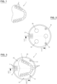
- FIG. 1 An exemplary Figure 1
- the dental prosthesis 1 shown with teeth 2 (partially provided with reference symbols) is scanned and recorded in a suitable design program.
- the design program can be used to plan the required changes to the digital image of the dental prosthesis 1.
- a blank 3 is created in a machine tool (additive or subtractive manufacturing).
- the blank 3 comprises a platform 5 on which a partial copy 7 of the dental prosthesis 1 is produced. Only the structures for referencing or for fixing in the counter are necessary: usually the chewing surfaces of the prosthetic teeth. Outside the area of the dental prosthesis 7, key structures 9 and 10 are also produced by the machine tool that produces the duplicate 7.
- the key structure 9 essentially consists of an arrangement of circular studs 11 (here six studs) similar to known plug-in modules.
- the blank (base) 3 consists of a dimensionally stable material and in particular a material that serves as a component of the workpiece after machining.
- the material can be pink plastic, often PMMA or another physiologically acceptable polymer or base material, which is used as a lining material for dental prostheses.
- Steel, plastic, titanium, model casting, in particular fiber-reinforced plastic, and ceramic are also conceivable.
- it can carry the necessary provisions (not shown here) such as grooves, bores, etc. that are required to attach it to a machine tool, preferably in a precisely defined position.
- a complementary counterpart can be attached, whereby a very precise positioning of the counterpart can be achieved, also with regard to rotational movement.
- the second type of key structure 10 shows an alternative, whereby several (here two) are produced on the blank, which individually still allow freedom of movement of a complementary counter-key, but as a whole also bring about precise positioning. Circular cylindrical knobs 11 are shown. At least one additional key structure, which is arranged at a distance from the other, is advantageous in order to increase the accuracy of the positioning.
- the number of studs is not important. At least 2 (since two studs not only prevent displacement but also rotation) are conceivable, 3, 4, 5, 6, 7, 8 and more studs, or an irregular configuration that essentially only allows a relative position to a counterpart. Also conceivable are studs that do not have a circular cross-section, such as elliptical, oval, egg-shaped, polygonal (preferably 3-cornered to 6-cornered, in order to obtain more pronounced corners and thus high resistance to twisting, whereby higher numbers of corners are conceivable in principle, but form a transition to the properties of a stud with a circular cross-section) and which individually prevent twisting around the vertical axis of the stud.
- An arrangement of at least 2 studs is preferable in terms of anti-twisting, and a plurality of studs generally offers greater positioning precision on a counterpart due to a larger ratio between the effective area of the key structure (stud arrangement) and the total area of the blank or prosthesis, or the maximum diameter (e.g. the distance between the centers [centers of gravity] of the studs arranged furthest apart from each other) of the key structure to the largest diameter of the prosthesis or blank as a whole (here, because of the circular shape: its diameter). Accordingly, the arrangement of more than one key structure, here the prototype of the key structure 9 and the simpler key structures 10, also serves to increase this ratio and thus to provide more precise positioning.
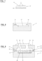
- the prosthesis or the workpiece in general does not have to be completely duplicated, it is sufficient to create a sufficient number of distinctive parts so that the original part can be positioned precisely and clearly in an impression made from the duplicate. As in Figure 4 visible, this can in particular be a sufficiently large number of chewing surfaces of the duplicate 7 or the dental prosthesis 1. Obviously, those areas that are intended for processing are not usable.
- a suitable casting compound 17 (gypsum; thermoplastic or permanently hardenable (e.g. by cross-linking) polymer material) and a reference key holder 19 are applied to the blank 3 (see Figure 5 ).
- the reference key holder 19 (see Figure 2 ) has key structures 21, 22, which are complementary to the key structures 9, 10 of the blank.
- the openings 24 serve to anchor the hardened impression to the reference key holder 19 by the passage of the impression material 17.
- a so-called counter 25 or counterpart is present, which essentially consists of the reference key holder 19 and the hardened impression material 17 and has on its surface at least in part an exact (negative) image 20 of the surface of the duplicate 7.
- the reference key holder 19 rests against the blank and in particular the key structures 9, 10 and 21, 22 engage with one another so that the counter 25 can be reattached to the blank in exactly this position.
- the figure shows that the distance is predetermined by the height of the edge 26, so that the key structures must be high enough to engage with one another, but do not determine the distance between the blank 3 and the reference key holder 19.
- the key structures 9, 10 and 21, 22 also determine the distance between the blank 3 and the reference key holder 19, i.e. that they rest against each other.
- the edge 26 can then still be present as a circumferential elevation, e.g. to prevent the leakage of fixing agent 29 (see below) from the blank 3.
- Figure 6 represents the counter 25 separated from the blank 3.
- the duplicate 7 is removed in order to obtain a free space 27 for receiving the dental prosthesis 1.
- a suitable amount of a flowable material 29 is introduced into the free space 27.
- This material 29 can be a construction material that is later used to represent a part of the prosthesis 1.
- Another suitable material that is suitable for pressing the prosthesis 1 onto the impression 20 in the counter 25 is also conceivable.
- the dental prosthesis 1 is, for example, as shown in Figure 7 shown reduced down to the teeth 2, which means that in any case all of the relining impression material is removed.
- the reduced prosthesis, which is milled flat at the bottom, can be attached to the blank 3 with an adhesive as a fixing agent 29, which itself serves as the material of the dental prosthesis.
- the blank 3 is also made of imitation material. Polymethylmethacrylate is known for this purpose, which is suitably colored to serve as a gingiva imitation.
- a larger amount of gingiva imitation material can also be filled into the free space 27 on the blank 3 as a fixing agent 29 and the (reduced) prosthesis 31 can be placed on top.
- the counter 25 is placed on top, whereby the reduced prosthesis 31 is pressed into the fixing agent 29, which here also serves as the raw material for the imitation of the gingiva on the dental prosthesis.
- Fixing material in a thick layer generally serves to press the prosthesis onto and even into the impression material, compensating for deviations in the adjacent surfaces, and to hold it there until the fixing agent has solidified.
- the fixing agent 29 is at least viscous to kneadable.
- a thixotropic material or another material that loses viscosity under an external influence such as mechanical stress, e.g. vibration or displacement, when heated or irradiated, or that liquefies sufficiently and automatically returns to a solid state is also conceivable.
- Irreversible hardening or solidification e.g. polymerization or cross-linking, is regularly carried out, and particularly when the fixing agent forms part of the processed prosthesis.
- the latter can be achieved by heating, irradiation (electromagnetic radiation such as light, microwaves, X-rays, corpuscular radiation (elementary particles such as electrons) or combinations thereof. Time-controlled curing by delayed activation of an added catalyst for polymerization is also conceivable.
- the prosthesis 1 is now in a precisely defined position on the counter 25 due to the exact fit on the impression 20, here by at least part of the chewing surfaces 15, and on the other hand the counter 25 itself is in a precisely defined position relative to the blank 3 due to the precise fit of the key structures 9, 11 and 21, 22. Overall, the dental prosthesis 1 is therefore in exactly the position in which the duplicate 7 of the dental prosthesis 1 was made on the blank 3.
- the counter 25 can be lifted off the blank 3 in a conceivable variant with the reduced dental prosthesis temporarily attached to it in a suitable manner and the polymer material adhering to it, the fixing agent 29, which here, however, has no special adhesive effect on the blank 3, and positioned in a machine tool by means of the reference key holder 19.
- the attachment of the prosthesis 1 to the counter 25 can be carried out, for example, by means of an adhesive (generally an adhesion-promoting substance) which is previously applied to at least part of the contact zones between the impression 20 and the prosthesis 1.
- an adhesive generally an adhesion-promoting substance
- the strength of the adhesion at least such an area must be covered that the requirements of subsequent processing steps are met.
- the entire contact surface of the impression 20 is provided with adhesive.
- the adhesive is selected to be suitable so that after processing it can be dissolved, weakened (e.g. by heating) or otherwise rendered ineffective or destroyed sufficiently so that the prosthesis can be removed from the counter 25 without being damaged. It is also possible for the machine to subtractively process the bonding surfaces (grinding).
- the counter 25 is lifted off after the fixing agent 29 has hardened.
- the blank 3 with prosthesis 1 is fixed in the machine tool for processing in a manner known per se.
- the gingiva imitation can be machined without damaging the prosthesis.
- the fixing means 29 can be designed as a stable, but later releasable connection to the blank 3. Due to the above-mentioned precise positioning of all parts according to Figure 9 The prosthesis is now also precisely positioned on the blank 3 and can therefore be precisely machined in a machine tool, since the coordinates of the scan of the prosthesis according to Figure 1 can be converted into the coordinates of the machine tool.
- the exact arrangement of the counter 25 or the blank 3 with the prosthesis 1 in the machine tool is problematic, it is possible to attach it to the machine tool without precise positioning.
- the target position of the key structures 9, 10 or 21, 22 in machine coordinates is not known or the key structures are not suitable for precise position determination, e.g. by scanning, machine referencing marks 33 can be attached at predetermined positions, e.g. small holes.
- the blank 3 or the counter 25 is then scanned. From the relative position of the machine reference markings 33 and the key structures 9, 10 or 21, 22, a mapping function of the design data to the machine coordinates can be created.
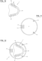
- reference bodies 41 are glued to the prosthesis 1, for example with wax.
- the reference beads 41 are attached to points as far away as possible, in the example on one of the front teeth and on the molars furthest back.
- Beads i.e. small spheres, have the advantage that they can be glued in any position and offer the same image from all directions.
- other small bodies that are easily recognizable and whose position in space can be precisely determined are also conceivable. They should be large enough to still be easily recognizable, but also small enough to be easy to glue on and not to interfere with the further steps. Sizes (diameters) in the range of a few millimeters are preferred, e.g.
- the material for the beads, or bodies in general should be one that is easy to scan, i.e. has a clear Contrast and sharp contours. Depending on the background, white or black is recommended, or perhaps a color that provides a high contrast to the background. A matte surface is advantageous in order to suppress reflections from the surroundings.
- the reference beads 41 (or more generally reference bodies or markings) must obviously be attached at sufficiently different locations (preferably as far apart as possible from each other) that they can be distinguished, i.e. the length and position of a line in space that connects the beads can be determined with sufficient resolution. Additional beads must generally not lie on an existing connection between two beads, or in a plane formed by three other beads if there are at least four beads.
- a basic set of reference features consists of features, none of which is part of a geometric object (line, polygon) that is defined by any subset of the other reference features.
- the prosthesis 1 with reference beads 41 is scanned. Based on the scanned data, which allows the creation of a virtual duplicate, the required processing steps are defined in a suitable design software such as a CAM system. Essentially, a virtual image is created (see Fig. 12 ) of the blank 3 with prosthesis 1, the workpiece, and additionally the key structures 9, 10 as well as the reference bodies 41. The processing steps are defined on this image.
- a blank 3 ( Figure 11 ) is provided with key structures 9, 10 in the machine tool.
- the key structures serve as machine reference markings for determining the position of the coordinate system of the machine tool, since they are formed at the locations that correspond to data specified by the CAM system. Structures that are clearly visible in a scan and allow high precision in determining the position are preferred.
- Such a machine reference marking can simply consist of a hole (diameter, for example, maximum 5 mm, preferably maximum 3 mm). Elevations can also be advantageous, e.g. conical or pyramidal, where the respective tip can be determined more precisely by cutting the flanks. Arrangements or different types can be used to differentiate, such as the structure 9 in the figures, which differs from the structures 10.
- the blank 3 is, if necessary, provided with an exposed surface 43 on which the dental prosthesis 1 can be arranged (see Figure 14 ).
- the prosthesis 1 is attached to the blank as in the first embodiment, either in the surface 43 or after removing (eg by milling) the duplicate 7 as in Figure 12 shown.
- the dental prosthesis 1 is placed upright as in Figure 15 shown or attached with the bottom side facing upwards, depending on whether the top or the bottom side has to be machined, or the counter 25 is used as described above in order to be able to machine the bottom side.
- the position of the prosthesis on the blank 3 certainly does not match, or at least not exactly enough, the position according to the design (see Figure 12 ), which is indicated in a broken line as the contour of the duplicate 7.
- the position of the prosthesis 1 on the blank 3 can now be determined by a new scan, in particular of the reference beads 41.
- the displacement ⁇ P1, ⁇ P2, ⁇ P3 of the construction points (here three, namely P1, P2 and P3) can now be determined in relation to the positions measured on the real prosthesis 1 (P1', P2', P3').
- the aforementioned methods make it possible to maintain the required precision, at least for the post-processing of dental prostheses. This usually involves determining the processing coordinates with a tolerance of around 30 ⁇ m (0.03 mm). A deviation of no more than 0.5 mm can be considered the lower limit of processing accuracy; deviations of no more than 0.2 mm and especially 0.1 mm are better and more suitable for practical use.
- the data processing steps in the preceding description are preferably carried out automatically on a computer or processor based on a program. This applies in particular to the conversion of the scanned images into the representation of the CAM system and the conversion of the CAM data to the coordinate system of the real prosthesis or the real workpiece in the position it occupies in the blank and in the machine tool.
Landscapes
- Health & Medical Sciences (AREA)
- Engineering & Computer Science (AREA)
- Mechanical Engineering (AREA)
- Veterinary Medicine (AREA)
- Animal Behavior & Ethology (AREA)
- Public Health (AREA)
- General Health & Medical Sciences (AREA)
- Life Sciences & Earth Sciences (AREA)
- Oral & Maxillofacial Surgery (AREA)
- Dentistry (AREA)
- Epidemiology (AREA)
- Manufacturing & Machinery (AREA)
- General Physics & Mathematics (AREA)
- Physics & Mathematics (AREA)
- Automation & Control Theory (AREA)
- Human Computer Interaction (AREA)
- Dental Prosthetics (AREA)
- Dental Tools And Instruments Or Auxiliary Dental Instruments (AREA)
- Machine Tool Sensing Apparatuses (AREA)
- Numerical Control (AREA)
Abstract
Eine Variante eines Verfahrens zum genauen Positionieren eines Werkstücks, insbesondere einer Zahnprothese (1), in einer Werkzeugmaschine besteht darin, an einem bezüglich der Werkzeugmaschine genau positionierbaren Teil einen Abdruck in ebenfalls bekannter Position in der Werkzeugmaschine zu erzeugen, um das Werkstück genau am Abdruck und damit in der Werkzeugmaschine zum Bearbeiten anordnen zu können. Eine Vorrichtung dazu umfasst einen Rohling (3) und ein Gegenstück oder Konter (25), an dem ein Abdruck (20) gebildet wird. Rohling und Konter weisen Schlüsselstrukturen (9, 10; 21, 22) auf, um sie voneinander trennen und reproduzierbar in gleicher Anordnung relativ zueinander wieder verbinden zu können. Eine Alternative auf rechnerischer Basis besteht darin, das Werkstück mit Referenzierkörpern (41) zu versehen, deren Positionen durch Scannen des Werkstücks (1) zu ermitteln, wobei auf der Basis des Scans Bearbeitungsschritte erzeugt werden, und Scannen in einer Werkzeugmaschine des (vorbereiteten) Werkstücks auf einem Rohling mit Schlüsselstrukturen (9, 10), deren Werkzeugmaschinenkoordinaten bekannt sind, um die Lage des Werkstücks in der Werkzeugmaschine sowohl in Werkzeugmaschinen- als auch in Kontruktionssystemkoordinaten zu bestimmen.A variant of a method for the precise positioning of a workpiece, in particular a dental prosthesis (1), in a machine tool consists in producing an impression in a known position in the machine tool on a part that can be positioned precisely with respect to the machine tool, in order to be able to arrange the workpiece precisely on the impression and thus in the machine tool for processing. A device for this purpose comprises a blank (3) and a counterpart or counter (25) on which an impression (20) is formed. The blank and counter have key structures (9, 10; 21, 22) in order to be able to separate them from one another and reproducibly reconnect them in the same arrangement relative to one another. A computationally based alternative consists in providing the workpiece with reference bodies (41), the positions of which are determined by scanning the workpiece (1), machining steps being generated on the basis of the scan, and scanning in a machine tool of the (prepared) workpiece on a blank with key structures (9, 10) whose machine tool coordinates are known in order to determine the position of the workpiece in the machine tool in both machine tool and design system coordinates.
Description
Die vorliegende Erfindung betrifft Verfahren zum Positionieren eines Werkstücks gemäss Oberbegriff des Anspruchs 1. Des weiteren betrifft Sie eine Vorrichtung zum Positionieren eines Werkstücks gemäss Oberbegriff des unabhängigen Vorrichtungsanspruchs.The present invention relates to methods for positioning a workpiece according to the preamble of
Das bevorzugte Einsatzgebiet und der Ausgangspunkt vorliegender Erfindung ist die Herstellung und nachträgliche Veränderung von Zahnprothesen. Die Erfindung ist jedoch anwendbar auf die Herstellung ganz generell von Werkstücken und insbesondere deren nachträgliche Bearbeitung, wie z. B. Motorenteile, Auto-, Flugzeug-, Schiffs-, Maschinen-, Modellbau- und andere Teile, Werkzeuge usw.The preferred field of application and the starting point of the present invention is the manufacture and subsequent modification of dental prostheses. However, the invention is applicable to the manufacture of workpieces in general and in particular to their subsequent processing, such as engine parts, car, aircraft, ship, machine, model building and other parts, tools, etc.
Bestehende Zahnprothesen müssen aus verschiedenen Gründen überarbeitet und angepasst werden. Ein häufiger Grund ist die Änderung des Kiefers, die eine Anpassung der Zahnprothese durch eine Unterfütterung erzwingt, das heisst das Auffüllen entstehender Hohlräume zwischen Zahnfleisch und Prothese. Auch nach dem Entfernen eines oder mehrerer Zähne müssen Zähne und / oder Prothesenbasis verändert werden. Halteelemente, wie Klammern, Implantatabutments, Geschiebe müssen verändert und / oder eingearbeitet werden. Im Zuge einer Neuanfertigung muss eine Zahnprothese anprobiert, gegebenenfalls Probe getragen und entsprechend den Rückmeldungen des Patienten korrigiert werden.Existing dentures must be revised and adjusted for various reasons. A common reason is a change in the jaw, which requires the denture to be adjusted by relining, i.e. filling in the gaps that arise between the gums and the denture. Even after one or more teeth have been removed, the teeth and/or denture base must be changed. Retaining elements such as clasps, implant abutments and attachments must be changed and/or incorporated. When making a new denture, a denture must be tried on, worn on a trial basis if necessary and corrected based on the patient's feedback.
Für Änderungen von Zahnprothesen kommen subtraktive (Schleifen, Fräsen) und additive (3D-Druck, insbesondere Metall-Laserschmelzverfahren) Bearbeitungsverfahren zum Einsatz. Bei jedem dieser Verfahren muss die Prothese (oder allgemein ein Werkstück) exakt in einer definierten Position in den Werkstückhalter der jeweiligen Werkzeugmaschine eingesetzt werden. Eine derartige Positionierung in der erforderlichen Genauigkeit (üblicherweise in der Grössenordnung von 0,1 mm oder besser) ist jedoch sehr aufwändig und zeitraubend. Dieses Problem rührt daher, dass Werkzeugmaschinen Bearbeitungsvorgänge gemäss Daten ausführen, die von einer Konstruktionssoftware (CAM-System) oder einer anderen Quelle stammen, ohne dass die Beziehung der Lage der Koordinatensysteme von Werkzeugmaschine und vom CAM-System, dem Konstruktionskoordinatensystem, zueinander bekannt ist.Subtractive (grinding, milling) and additive (3D printing, especially metal laser melting) machining processes are used to modify dental prostheses. In each of these processes, the prosthesis (or generally a workpiece) must be inserted into the workpiece holder of the respective machine tool in a precisely defined position. However, such positioning with the required accuracy (usually in the order of 0.1 mm or better) is very complex and time-consuming. This problem arises from the fact that machine tools carry out machining operations according to data that comes from design software (CAM system) or another source, without the relationship between the position of the coordinate systems of the machine tool and the CAM system, the design coordinate system, being known.
Eine Aufgabe der vorliegenden Erfindung besteht daher darin, das genaue Positionieren eines Werkstückes in einer Werkzeugmaschine einfacher zu gestalten.An object of the present invention is therefore to make the precise positioning of a workpiece in a machine tool easier.
Ein entsprechendes Verfahren ist im Verfahrensanspruch angegeben. Die weiteren Ansprüche geben bevorzugte Ausführungsformen des Verfahren und Vorrichtungen zum Einsatz in diesem Verfahren an.A corresponding method is specified in the method claim. The further claims specify preferred embodiments of the method and devices for use in this method.
Bei dem Verfahren wie auch der Vorrichtung wird ausgenutzt, dass es mit geringem Aufwand möglich ist, aufgrund der vorliegenden Konstruktion, das heisst digitalen Daten zur Steuerung einer numerisch gesteuerten (computergesteuerten) Werkzeugmaschine, ein Duplikat des jeweiligen Werkstücks formgetreu aus einem preiswerten Material herzustellen. Das Duplikat wird auf einer Basis oder Plattform hergestellt und bildet mit dieser einen sogenannten Rohling. Von dem Duplikat wird auf einem Gegenstück, dem sogenannten Konter, ein Abdruck erstellt. Der Abdruck kann sich dabei auf ausgewählte Stellen des Duplikats beschränken, die insgesamt hinreichend prägnant sind, so dass beim Entfernen des Duplikats und Wiederaufsetzen auf den Abdruck reproduzierbar das Duplikat bzw. in einem späteren Schritt das Original des Werkstücks in der gleichen Position auf dem Abdruck einrastet. Bei einer Zahnprothese können diese prägenden Stellen hinreichend ausgedehnte Oberflächenabschnitte der Zähne, das heisst deren Kauflächen, aber auch die Unterseite der Prothese oder die Aussenflächen sein. Falls dabei an den Zähnen eine Bearbeitung vorgesehen ist, sind diese natürlich nicht für diese Referenzzonen verfügbar.The method and the device exploit the fact that it is possible with little effort to produce a duplicate of the respective workpiece from an inexpensive material with the same shape as the existing design, i.e. digital data for controlling a numerically controlled (computer-controlled) machine tool. The duplicate is produced on a base or platform and forms a so-called blank with it. An impression of the duplicate is made on a counterpart, the so-called counter. The impression can be limited to selected areas of the duplicate that are sufficiently distinctive overall so that when the duplicate is removed and replaced on the impression, the duplicate or, in a later step, the original of the workpiece snaps into place in the same position on the impression in a reproducible manner. In the case of a dental prosthesis, these distinctive areas can be sufficiently extensive surface sections of the teeth, i.e. their chewing surfaces, but also the underside of the prosthesis or the outer surfaces. If processing is planned on the teeth, these are of course not available for these reference zones.
Der Konter weist einen Positionierungsabschnitt auf, der bevorzugt ausserhalb des Bereichs liegt, der vom Werkstück abgedeckt wird. In diesem Positionierungsabschnitt sind eine oder mehrere Schlüsselstrukturen angeordnet. Die Schlüsselstrukturen sind derart ausgebildet, dass sie es gestatten, den Konter auf einer Basis, in der Regel einem Rohling, genau in einer vorgegebenen Position anzubringen. Die Gegenstücke zu den Schlüsselstrukturen am Konter, die Rohlingschlüsselstrukturen, werden von der jeweiligen Werkzeugmaschine hergestellt. Ihre Position ist also im Koordinatensystem der Werkzeugmaschine bekannt. Somit ist auch die Position der Schlüsselstrukturen am Konter bezüglich des Abdrucks der Referenz des Werkstücks, insbesondere einer Zahnprothese, bekannt. Insgesamt ist es damit möglich, die Position eines Werkstücks (einer Zahnprothese), das am Rohling oder auch am Abdruck des Konters angebracht ist, sowie die genaue Positionierung des Konters über die Schlüsselstrukturen am Rohling genau bezüglich des Koordinatensystems der Werkzeugmaschine festzulegen. Durch das Fräsen des Duplikates zeigt die Maschine, in welcher Position sie das Werkstück bearbeitet. Durch Verwendung des Konters wird dann das Werkstück in exakt dieser Position fixiert.The counter has a positioning section that is preferably located outside the area covered by the workpiece. One or more key structures are arranged in this positioning section. The key structures are designed in such a way that they allow the counter to be attached to a base, usually a blank, in a precise position. The counterparts to the key structures on the counter, the blank key structures, are manufactured by the respective machine tool. Their position is therefore known in the coordinate system of the machine tool. The position of the key structures on the counter with respect to the impression of the reference of the workpiece, in particular a dental prosthesis, is therefore also known. Overall, it is thus possible to determine the position of a workpiece (a dental prosthesis) that is attached to the blank or to the impression of the counter, as well as the precise positioning of the counter via the key structures on the blank precisely with respect to the coordinate system of the machine tool. By milling the duplicate, the machine shows in which position it is machining the workpiece. By using the counter, the workpiece is then fixed in exactly this position.
Mit diesem Wissen ist es möglich, die Konstruktion in Werkzeugkoordinaten umzurechnen, womit genau an den geplanten Stellen eine definierte Bearbeitung des Werkstücks möglich ist.With this knowledge, it is possible to convert the design into tool coordinates, which enables defined machining of the workpiece at exactly the planned locations.
Eine andere Möglichkeit, die Koordinatensysteme von Werkzeugmaschine, Konstruktion (CAM-Daten) und Werkstück aufeinander abzubilden, besteht darin, einen Scan des Werkstücks auszuführen, wenn es sich in der Werkzeugmaschine auf einem Rohling befindet, wobei vorgängig Referenziermerkmale an definierten Positionen des Werkstücks und Schlüsselmerkmale am Rohling angebracht werden. Die Schlüsselmerkmale werden dabei jedenfalls von der Werkzeugmaschine erzeugt, wodurch diese vorgegebenen Koordinaten der Werkzeugmaschine entsprechen. Durch die Referenziermerkmale am Werkstück ist eine exakte Erkennung der Lage des Werkstücks im Scan möglich. Alternativ kann auf prägnante Merkmale des Werkstücks selbst zurückgegriffen werden. Oft führt dies jedoch zu einer geringeren Präzision der Erkennung der Lage des Werkstücks im Raum und zu einem erhöhten Rechenaufwand.Another way to map the coordinate systems of the machine tool, design (CAM data) and workpiece to one another is to perform a scan of the workpiece when it is on a blank in the machine tool, whereby reference features are first attached to defined positions on the workpiece and key features are attached to the blank. The key features are generated by the machine tool, which means that they correspond to the specified coordinates of the machine tool. The reference features on the workpiece enable the exact detection of the position of the workpiece in the scan. Alternatively, you can use distinctive features of the workpiece itself. However, this often leads to a lower precision in the detection of the position of the workpiece in space and to increased computing effort.
Die Erfindung wird weiter an Ausführungsbeispielen unter Bezugnahme auf Figuren erläutert. Es zeigen:
Figur 1- Draufsicht auf eine Zahnprothese als Prototyp eines Werkstücks;
Figur 2- Ansicht von unten auf eine Trägerplatte für einen Konter (Gegenstück);
Figur 3- Draufsicht auf Rohling (Basis) mit Werkstück (Zahnprothese);
Figur 4- Schnitt gemäss IV - IV in
Figur 3 - Figur 5
- Schnitt gemäss V - V in
Figur 2Fig. 3 nach Ausbilden des Werkstücknegativs (Prothesenabdruck); - Figur 6
- Schnitt wie
Figur 5 , Abdruck vom Rohling abgehoben; Figur 7- Seitenansicht auf eine reduzierte Prothese;
- Figur 8
- Schnitt durch einen Rohling gemäss VIII - VIII in
Fig. 13 , Raum für Prothese freigelegt; Figur 9- Darstellung analog
Figur 6 , reales Werkstück (Zahnprothese) in Aufnahme gemässFigur 8 eingelegt und Gegenstück mit Abdruck aufgesetzt; Figur 10- Draufsicht auf Zahnprothese mit Referenzierkügelchen;
Figur 11- Draufsicht auf Rohlingplattform mit Schlüsselstrukturen;
- Figur 12
- Virtueller Rohling mit Werkstück;
- Figur 13
- Draufsicht auf Rohling mit Aussparung für eine Prothese;
- Figur 14
- Draufsicht auf Rohling gemäss
Figur 13 mit eingelegter Prothese, Idealposition gem.Fig. 12 gestrichelt; Figur 15- Schnitt gemäss XV - XV in
Figur 14 ; und - Figur 16
- Draufsicht analog
Figur 14 mit Angabe von Referenzpunkten (schematisiert).
- Figure 1
- Top view of a dental prosthesis as a prototype of a workpiece;
- Figure 2
- View from below of a carrier plate for a counter (counterpart);
- Figure 3
- Top view of blank (base) with workpiece (dental prosthesis);
- Figure 4
- Cut according to IV - IV in
Figure 3 ; - Figure 5
- Cut according to V - V in
Figure 2 and IV.-IV inFig.3 after forming the workpiece negative (prosthesis impression); - Figure 6
- Cut like
Figure 5 , impression lifted from the blank; - Figure 7
- Side view of a reduced prosthesis;
- Figure 8
- Section through a blank according to VIII - VIII in
Fig. 13 , space for prosthesis cleared; - Figure 9
- Analog representation
Figure 6 , real workpiece (dental prosthesis) in recording according toFigure 8 inserted and counterpart with impression placed on top; - Figure 10
- Top view of dental prosthesis with reference beads;
- Figure 11
- Top view of blank platform with key structures;
- Figure 12
- Virtual blank with workpiece;
- Figure 13
- Top view of blank with recess for a prosthesis;
- Figure 14
- Top view of blank according to
Figure 13 with inserted prosthesis, ideal position acc.Fig. 12 dashed; - Figure 15
- Section according to XV - XV in
Figure 14 ; and - Figure 16
- Top view analog
Figure 14 with indication of reference points (schematic).
Gemäss erstem Ausführungsbeispiel wird ein Werkzeug hergestellt, das es gestattet, eine Zahnprothese oder allgemein ein Werkstück derart in einer Werkzeugmaschine anzuordnen, dass seine Lage exakt mit einer vorhandenen, numerischen Konstruktion übereinstimmt. Die Konstruktion kann für Anpassungen oder Modifizierungen überarbeitet werden, wonach mit Hilfe einer Werkzeugmaschine exakt an den vorgegebenen Stellen am realen Objekt die Änderungen unter numerischer Steuerung vorgenommen werden.According to the first embodiment, a tool is produced that allows a dental prosthesis or a workpiece in general to be arranged in a machine tool in such a way that its position corresponds exactly to an existing numerical design. The design can be revised for adjustments or modifications, after which the changes are made under numerical control with the help of a machine tool at exactly the specified locations on the real object.
Eine beispielhaft in
Der Rohling (Basis) 3 besteht aus einem formstabilen Material und insbesondere einem Material, das als Bestandteil des Werkstücks nach der Bearbeitung dient. Z. B. kann es sich bei dem Material um rosafarbenen Kunststoff, oft PMMA oder ein anderes physiologisch akzeptables Polymer oder Basismaterial, handeln, der als Unterfütterungsmaterial bei Zahnprothesen eingesetzt wird. Denkbar ist auch Stahl, Kunststoff, Titan, Modellguss, insbesondere faserverstärkter Kunststoff, und Keramik. Ausserdem kann sie die erforderlichen Vorkehrungen (hier nicht dargestellt) wie Nuten, Bohrungen usw. tragen, die benötigt werden, um sie in einer Werkzeugmaschine, bevorzugt in genau festgelegter Position, anzubringen.The blank (base) 3 consists of a dimensionally stable material and in particular a material that serves as a component of the workpiece after machining. For example, the material can be pink plastic, often PMMA or another physiologically acceptable polymer or base material, which is used as a lining material for dental prostheses. Steel, plastic, titanium, model casting, in particular fiber-reinforced plastic, and ceramic are also conceivable. In addition, it can carry the necessary provisions (not shown here) such as grooves, bores, etc. that are required to attach it to a machine tool, preferably in a precisely defined position.
Offensichtlich kann ein dazu komplementär ausgebildetes Gegenstück aufgesteckt werden, wodurch eine sehr genaue Positionierung des Gegenstücks auch bezüglich Drehbewegung erzielbar ist. Der zweite Typ Schlüsselstruktur 10 zeigt eine Alternative, wobei mehrere (hier zwei) auf dem Rohling hergestellt werden, die zwar einzeln noch eine Bewegungsfreiheit eines aufgesetzten, komplementär gebildeten Gegenschlüssels gestatten, jedoch in der Gesamtheit ebenfalls eine genaue Positionierung bewirken. Gezeigt sind kreiszylindrische Noppen 11. Wenigstens eine zusätzliche Schlüsselstruktur, die beabstandet von der anderen angeordnet ist, ist jedoch vorteilhaft, um die Genauigkeit der Positionierung zu erhöhen.Obviously, a complementary counterpart can be attached, whereby a very precise positioning of the counterpart can be achieved, also with regard to rotational movement. The second type of
Bei den Schlüsselstrukturen 9 und 10 sind vielfältige Formen denkbar, die von den dargestellten abweichen. Essentiell ist dabei, wie unten noch ausgeführt, dass ein daraufgesetztes Gegenstück in genau einer Position und ohne weitere Bewegungsmöglichkeit aufgesetzt werden kann. Naheliegend sind z.B. statt kreiszylindrischen Noppen polygonale oder jedenfalls von der Kreisform abweichende Formen, wie elliptisch und oval. Statt Noppen können auch Vertiefungen, also Bohrungen vorgesehen sein, wonach das Gegenstück entsprechend anstatt Vertiefungen Erhebungen entsprechender Form aufweisen muss oder umgekehrt.For
Die Zahl von Noppen ist nicht massgebend. Denkbar ist von mindestens 2 (da bereits zwei Noppen nicht nur eine Verschiebung verhindern, sondern auch eine Drehung), 3, 4, 5, 6, 7, 8 und mehr Noppen, oder auch eine unregelmässige, aber im Wesentlichen nur eine relative Position zu einem Gegenstück zulassende Konfiguration. Denkbar sind auch Noppen, die keinen kreisförmigem Querschnitt aufweisen, wie elliptisch, oval, eiförmig, polygonal (bevorzugt 3-eckig bis 6-eckig, um noch ausgeprägte Ecken und damit hohen Widerstand gegen Verdrehen zu erhalten, wobei höhere Eckenzahlen grundsätzlich denkbar sind, aber einen Übergang zu den Eigenschaften einer Noppe mit kreisförmigem Querschnitt bilden) und die bereits einzeln ein Verdrehen um die Hochachse der Noppe verhindern. Ein Anordnung von mindestens 2 Noppen ist bezüglich Verdrehsicherung vorzuziehen, und eine Mehrzahl von Noppen bietet grundsätzlich eine höhere Präzision der Positionierung auf einem Gegenstück durch ein grösseres Verhältnis zwischen wirksamer Fläche der Schlüsselstruktur (Noppenanordnung) und der Gesamtfläche des Rohlings bzw. der Prothese, bzw. des maximalen Durchmessers (bspw. die Entfernung der Mitten [Schwerpunkte] der am weitesten entfernt voneinander angeordneten Noppen) der Schlüsselstruktur zu dem grössten Durchmesser der Prothese oder des Rohlings insgesamt (hier wegen der Kreisform: sein Durchmesser). Entsprechend dient auch die Anordnung von mehr als einer Schlüsselstruktur, hier prototypisch der Schlüsselstruktur 9 und der einfacheren ausgeführten Schlüsselstrukturen 10 der Vergrösserung dieses Verhältnisses und damit der genaueren Positionierung.The number of studs is not important. At least 2 (since two studs not only prevent displacement but also rotation) are conceivable, 3, 4, 5, 6, 7, 8 and more studs, or an irregular configuration that essentially only allows a relative position to a counterpart. Also conceivable are studs that do not have a circular cross-section, such as elliptical, oval, egg-shaped, polygonal (preferably 3-cornered to 6-cornered, in order to obtain more pronounced corners and thus high resistance to twisting, whereby higher numbers of corners are conceivable in principle, but form a transition to the properties of a stud with a circular cross-section) and which individually prevent twisting around the vertical axis of the stud. An arrangement of at least 2 studs is preferable in terms of anti-twisting, and a plurality of studs generally offers greater positioning precision on a counterpart due to a larger ratio between the effective area of the key structure (stud arrangement) and the total area of the blank or prosthesis, or the maximum diameter (e.g. the distance between the centers [centers of gravity] of the studs arranged furthest apart from each other) of the key structure to the largest diameter of the prosthesis or blank as a whole (here, because of the circular shape: its diameter). Accordingly, the arrangement of more than one key structure, here the prototype of the
Die Prothese oder allgemein das Werkstück muss auch nicht vollständig dupliziert werden, es genügt vielmehr hinreichend viele, prägnante Teile auszubilden, dass das Originalteil in einem von dem Duplikat angefertigten Abdruck genau und eindeutig positioniert werden kann. Wie in
Auf den Rohling 3 wird eine geeignete Abgussmasse 17 (Gips; thermoplastisches oder dauerhaft härtbares (z.B. durch Vernetzen) polymeres Material) und ein Referenzierschlüsselhalter 19 aufgebracht (siehe
Der Referenzierschlüsselhalter 19 (siehe
Denkbar ist jedoch, dass die Schlüsselstrukturen 9, 10 und 21, 22 auch den Abstand zwischen Rohling 3 und Referenzierschlüsselhalter 19 festlegen, also auf Anschlag aneinander anliegen. Der Rand 26 kann jedoch dann immer noch als umlaufende Erhebung vorhanden sein, z. B. um das Auslaufen von Fixiermittel 29 (s.u.) aus dem Rohling 3 zu verhindern.However, it is conceivable that the
Für das Material des Referenzschlüsselhalters gelten dieselben Überlegungen wie für den Rohling 3 weiter oben angestellt.The same considerations apply to the material of the reference key holder as for blank 3 above.
Das Duplikat 7 wird abgetragen um einen Freiraum 27 zur Aufnahme der Zahnprothese 1 zu erhalten. In den Freiraum 27 wird ein fliessfähiges Material 29 in geeigneter Menge eingebracht. Dieses Material 29 kann ein Konstruktionsmaterial sein, das dazu dient, später einen Teil der Prothese 1 darzustellen. Denkbar ist auch ein anderes geeignetes Material, das geeignet ist, die Prothese 1 an den Abdruck 20 im Konter 25 anzupressen. Vorliegend wird beispielhaft die Zahnprothese 1 wie in
Auf dem Rohling 3 kann auch eine grössere Menge Gingivaimitatmaterial als Fixiermittel 29 im Freiraum 27 im Übermass eingefüllt und die (reduzierte) Prothese 31 aufgelegt werden. Der Konter 25 wird aufgesetzt, wobei die reduzierte Prothese 31 in das Fixiermittel 29 eingedrückt wird, das hier gleichzeitig als Rohmaterial für das Imitat der Gingiva an der Zahnprothese dient.A larger amount of gingiva imitation material can also be filled into the
Fixiermaterial in grösseren Schichtdicke dient generell dazu, die Prothese an und sogar in das Abdruckmaterial zu drücken, wobei Abweichungen der anliegenden Oberflächen ausgeglichen werden, und dort zu halten, bis das Fixiermittel verfestigt ist. Das Fixiermittel 29 ist wenigstens zähflüssig bis knetartig. Denkbar ist auch ein thixotropes Material oder ein anderes Material, das unter einem äusseren Einfluss wie einer mechanischer Belastung, z.B. Vibrieren oder Verschieben, bei Erwärmen oder Bestrahlen an Viskosität verliert bzw. überhaupt sich hinreichend verflüssigt und selbsttätig wieder in einen festen Zustand übergeht. Regelmässig, und insbesondere dann, wenn das Fixiermittel einen Teil der bearbeiteten Prothese bildet, wird eine irreversible Härtung oder Verfestigung vorgenommen, z.B. eine Polymerisierung oder Vernetzung. Letzteres kann durch Erwärmen, Bestrahlung (elektromagnetische Strahlung wie Licht, Mikrowellen, Röntgen, Korpuskularstrahlung (Elementarteilchen, wie Elektronen) oder Kombinationen daraus erzielt werden. Denkbar ist auch eine zeitgesteuerte Aushärtung durch verzögerte Aktivierung eines zugesetzten Katalysators für die Polymerisierung.Fixing material in a thick layer generally serves to press the prosthesis onto and even into the impression material, compensating for deviations in the adjacent surfaces, and to hold it there until the fixing agent has solidified. The fixing
Wie in
Für die weitere Bearbeitung kann der Konter 25 in einer denkbaren Variante mit der daran auf geeigneter Art vorübergehend befestigten reduzierten Zahnprothese und dem daran anhaftenden Polymermaterial, dem Fixiermittel 29, das hier jedoch keine besondere Haftwirkung zum Rohling 3 aufweist, vom Rohling 3 abgehoben und mittels des Referenzschlüsselhalters 19 in einer Werkzeugmaschine positioniert werden. Die Befestigung der Prothese 1 am Konter 25 kann z.B. durch einen Klebstoff (allgemein eine haftvermittelnde Substanz) erfolgen, der vorgängig auf wenigstens einem Teil der Kontaktzonen zwischen Abdruck 20 und Prothese 1 aufgetragen wird. Im Hinblick auf die Stärke der Haftvermittlung ist wenigstens ein solcher Bereich zu bedecken, dass die Anforderungen nachfolgender Bearbeitungsschritte erfüllt werden. Im einfachsten Fall wird die gesamte Kontaktfläche des Abdrucks 20 mit Klebstoff versehen. Der Klebstoff ist geeignet gewählt, um nach Bearbeitung aufgelöst, geschwächt (z.B. durch Erwärmen) oder anderweitig genügen unwirksam oder zerstört zu werden, dass die Prothese vom Konter 25 entfernt werden kann, ohne Schaden zu nehmen. Es ist auch eine subtraktive Bearbeitung der Klebeflächen durch die Maschine möglich (abschleifen).For further processing, the
Denkbar ist, den Klebstoff durch Einwirken eines Lösungsmittels zu entfernen, z.B. durch Eintauchen in ein Lösungsmittel. Eine weitere Möglichkeit ist eine starke Temperaturänderung, also Erwärmen oder auch Abkühlen, in einen Temperaturbereich, in der der Klebstoff Zusammenhalt oder Haftkraft oder beides wenigstens teilweise verliert.It is conceivable to remove the adhesive by exposing it to a solvent, e.g. by immersing it in a solvent. Another possibility is a strong change in temperature, i.e. heating or cooling, to a temperature range in which the adhesive loses at least some of its cohesion or adhesive strength or both.
Bevorzugt wird jedoch der Konter 25 nach Aushärten des Fixiermittels 29 abgehoben. Der Rohling 3 mit Prothese 1 wird auf eine an sich bekannte Art in der Werkzeugmaschine zur Bearbeitung fixiert.Preferably, however, the
Da sich nun die Prothese 1 innerhalb der Werkzeugmaschine in einer Position befindet, deren Koordinaten innerhalb der Werkzeugmaschine bekannt sind, kann eine Bearbeitung des Gingivaimitats erfolgen, ohne die Prothese zu beschädigen.Since the
Soll dagegen eine Änderung an den Kauflächen 15 der Zahnprothese 1 durchgeführt werden, so kann das Fixiermittel 29 als stabile, aber später wieder auflösbare Verbindung zum Rohling 3 ausgelegt sein. Durch die oben genannte genaue Positionierung aller Teile gemäss
Falls die genaue Anordnung des Konters 25 bzw. des Rohlings 3 mit der Prothese 1 in der Werkzeugmaschine problematisch ist, besteht die Möglichkeit, diese ohne genaue Positionierung an der Werkzeugmaschine anzubringen. Wenn die Sollposition der Schlüsselstrukturen 9,10 oder 21, 22 in Maschinenkoordinaten nicht bekannt sind oder die Schlüsselstrukturen nicht zur genauen Positionsbestimmung, z.B. durch Einscannen, geeignet sind, können an vorgegebenen Positionen Maschinenreferenzierungsmarken 33 angebracht werden, z. B. kleine Löcher. Dann wird der Rohling 3 bzw. der Konter 25 gescannt. Aus der relativen Position der Maschinenreferenzmarkierungen 33 und der Schlüsselstrukturen 9, 10 oder 21, 22 kann eine Abbildungsfunktion der Konstruktionsdaten auf die Maschinenkoordinaten erstellt werden. Im Resultat ist es damit möglich, die Konstruktionsdaten, die anhand des eingangs genannten Scans der Prothese 1 aus
Wie in
Die Referenzierkügelchen 41 (oder allgemeiner Referenzierkörper oder -markierungen) müssen offensichtlich an genügend verschiedenen Orten angebracht sein (bevorzugt in möglichst grossem Abstand voneinander), dass sie sich unterscheiden lassen, also mit hinreichender Auflösung Länge und Lage einer Strecke im Raum bestimmbar ist, die die Kügelchen verbindet. Weitere Kügelchen dürfen generell nicht auf einer bereits gegebenen Verbindung zweier Kügelchen liegen, oder in einer von drei anderen Kügelchen gebildeten Ebene bei mindestens 4 Kügelchen. Generell besteht also ein Basissatz von Referenziermerkmalen aus Merkmalen, von denen keines Teil eines geometrischen Objekts (Strecke, Polygon) ist, das durch eine beliebige Untermenge der anderen Referenziermerkmale definiert ist. Denkbar ist jedoch, zusätzliche, eigentlich redundante Kügelchen anzubringen, die der Erhöhung der Messgenauigkeit dienen, z.B. durch Mittelwertbildung, oder als Sicherheit für den Fall, dass eines der Kügelchen abfällt.The reference beads 41 (or more generally reference bodies or markings) must obviously be attached at sufficiently different locations (preferably as far apart as possible from each other) that they can be distinguished, i.e. the length and position of a line in space that connects the beads can be determined with sufficient resolution. Additional beads must generally not lie on an existing connection between two beads, or in a plane formed by three other beads if there are at least four beads. In general, a basic set of reference features consists of features, none of which is part of a geometric object (line, polygon) that is defined by any subset of the other reference features. However, it is conceivable to attach additional, actually redundant beads that serve to increase the measurement accuracy, e.g. by averaging, or as a safety net in the event that one of the beads falls off.
Denkbar ist, als Referenziermarkierung einen Oberflächenabschnitt der Prothese einzusetzen, der genügend charakteristisch ausgebildet ist. um mit Bilderkennungsverfahren erkannt und genau lokalisiert zu werden.It is conceivable to use a surface section of the prosthesis as a reference marking that is sufficiently characteristic to be recognized and precisely localized using image recognition methods.
Die Prothese 1 mit Referenzierkügelchen 41 wird eingescannt. Anhand der eingescannten Daten, die das Erstellen eines virtuellen Duplikats gestatten, werden die benötigten Bearbeitungsschritte in einer geeigneten Konstruktionssoftware wie ein CAM-System festgelegt. Im wesentlichen wird dabei ein virtuelles Bild (s.
Ein Rohling 3 (
Beispiels entsprechen, kann eine solche Maschinenreferenzmarkierung einfach aus einem Loch (Durchmesser beispielsweise maximal 5 mm, bevorzugt höchstens 3 mm) bestehen. Vorteilhaft können auch Erhebungen sein, z. B. kegelförmige oder pyramidale, wobei die jeweilige Spitze durch Schneiden der Flanken genauer bestimmt werden kann. Für eine Unterscheidung können Anordnungen oder unterschiedliche Arten verwendet werden, wie in den Figuren die Struktur 9, die sich von den Strukturen 10 unterscheidet.Example, such a machine reference marking can simply consist of a hole (diameter, for example, maximum 5 mm, preferably maximum 3 mm). Elevations can also be advantageous, e.g. conical or pyramidal, where the respective tip can be determined more precisely by cutting the flanks. Arrangements or different types can be used to differentiate, such as the
Der Rohling 3 wird, wenn nötig, mit einer freigelegten Fläche 43 versehen, auf der die Zahnprothese 1 angeordnet werden kann (siehe
Die Prothese 1 wird wie beim 1. Ausführungsbeispiel auf dem Rohling angebracht, entweder in der Fläche 43 oder nach Entfernen (z.B. durch Fräsen) des Duplikats 7 wie in
Auf der Fläche 43 wird die Zahnprothese 1 aufrecht wie in
Wie in
Vorstellbar ist dies schematisch z.B. durch folgendes Verfahren:
- 1. Punkt P1 wird auf P1' verschoben;
- 2. es folgt eine Drehung um eine Achse durch P1' (ist gleich P1), wobei die Drehachse senkrecht auf einem Dreieck steht, das durch P1', P2 und P2' gebildet wird. Durch diese Drehung wird Punkt P2 auf P2' gedreht, so dass P2 gleich P2' nach dieser Operation gilt;
- 3. eine Drehung um eine Achse durch P1' und P2' folgt, wobei P3 auf P3' bewegt wird.
- 1. Point P1 is moved to P1';
- 2. there follows a rotation around an axis through P1' (equal to P1), the axis of rotation being perpendicular to a triangle formed by P1', P2 and P2'. This rotation rotates point P2 to P2', so that P2 is equal to P2' after this operation;
- 3. a rotation around an axis through P1' and P2' follows, moving P3 to P3'.
Dabei werden auch Veränderungen senkrecht zu Zeichenebene, also real der Oberfläche der Plattform 5, berücksichtigt- Die Lagedifferenzen ΔP1 , ΔP2, ΔP3 können also auch eine Komponente senkrecht zur Zeichenebene enthalten.Changes perpendicular to the drawing plane, i.e. the actual surface of the platform 5, are also taken into account. The position differences ΔP1, ΔP2, ΔP3 can therefore also contain a component perpendicular to the drawing plane.
Verschiedene Massstäbe beim Scannen der Prothese 1 gemäss
Die vorgenannten Verfahren erlauben es, die erforderliche Präzision jedenfalls für die Nachbearbeitung von Zahnprothesen einzuhalten. Diese liegen in der Regel bei einer Bestimmung der Bearbeitungskoordinaten mit einer Toleranz von heutzutage ca. 30 µm (0,03 mm). Als untere Grenze der Verarbeitungsgenauigkeit kann eine Abweichung von höchstens 0,5 mm angesehen werden, besser und für die Praxis eher tauglich sind Abweichungen von höchstens 0,2 mm und insbesondere 0,1 mm.The aforementioned methods make it possible to maintain the required precision, at least for the post-processing of dental prostheses. This usually involves determining the processing coordinates with a tolerance of around 30 µm (0.03 mm). A deviation of no more than 0.5 mm can be considered the lower limit of processing accuracy; deviations of no more than 0.2 mm and especially 0.1 mm are better and more suitable for practical use.
Eine interessante Anwendung dieses Verfahrens, um ein Nachbearbeiten einer Prothese oder allgemein eines Werkstücks ohne seine Schädigung zu ermöglichen, liegt in seinem Einsatz bei der Herstellung. Gerade bei den additiven Bearbeitungsverfahren (3D-Druck) besteht ein grosses Preisgefälle zwischen Werkzeugmaschinen, die die erforderliche Endpräzision aufweisen, und solchen mit unzulässig hohen Toleranzen. Mithilfe obigen Verfahrens ist es denkbar, ein Werkstück, insbesondere ein zahntechnisches oder sonstiges Modell, zunächst mit einer Werkzeugmaschine geringerer Genauigkeit und entsprechendem Übermass herzustellen und das Produkt dann in einer Werkzeugmaschine, in der Regel einer Werkzeugmaschine der subtraktiven Fertigung wie einer Fräse, nachzuarbeiten, wobei die exakte Position des Werkstücks in der Fräse mit dem vorliegenden Verfahren ermittelt wird.An interesting application of this process to enable reworking of a prosthesis or a workpiece in general without damaging it is its use in manufacturing. Especially with additive machining processes (3D printing), there is a large price difference between machine tools that have the required final precision and those with unacceptably high tolerances. Using the above process, it is conceivable to first produce a workpiece, in particular a dental or other model, with a machine tool of lower precision and corresponding oversize and then to rework the product in a machine tool, usually a subtractive manufacturing machine tool such as a milling machine, whereby the exact position of the workpiece in the milling machine is determined using the present process.
Die Datenverarbeitungsschritte in der vorangehenden Beschreibung werden bevorzugt automatisiert auf einem Computer oder Prozessor auf der Grundlage eines Programms ausgeführt. Insbesondere gilt das für die Umrechnung der gescannten Bilder in die Darstellung des CAM-Systems und die Umrechnung der CAM-Daten auf das Koordinatensystem der realen Prothese bzw. des realen Werkstücks in der Position, die es im Rohling und in der Werkzeugmaschine einnimmt.The data processing steps in the preceding description are preferably carried out automatically on a computer or processor based on a program. This applies in particular to the conversion of the scanned images into the representation of the CAM system and the conversion of the CAM data to the coordinate system of the real prosthesis or the real workpiece in the position it occupies in the blank and in the machine tool.
Aus der vorangehenden Beschreibung der Ausführungsbeispiele sind dem Fachmann vielfältige Abwandlungen und Ergänzungen zugänglich, ohne den Schutzbereich der Erfindung zu verlassen, der durch die Ansprüche definiert ist. Einige denkbare Varianten sind in der Beschreibung der Ausführungsbeispiele erwähnt.From the above description of the embodiments, a wide variety of modifications and additions are accessible to the person skilled in the art without departing from the scope of the invention, which is defined by the claims. Some conceivable variants are mentioned in the description of the embodiments.
Denkbar ist auch:
- Die Erfindung wird bei der Nachbearbeitung von beliebigen Werkstücken angewendet.
- Der Rohling wird nicht zu einem Teil des Werkstücks und dient damit ausschliesslich als Basis. Er kann also aus einem Material bestehen, das ihn als Werkstückhalter in dem angewendeten Bearbeitungsverfahren besser geeignet macht.
- Der Abstand der Schlüsselstrukturen bzw. der Maschinenreferenzmarkierungen beträgt mindestens 113 eines grössten Durchmessers des Werkstücks in der Projektion auf den Rohling bzw. die Basis.
- The invention is used in the post-processing of any workpiece.
- The blank does not become part of the workpiece and therefore serves only as a base. It can therefore be made of a material that makes it more suitable as a workpiece holder in the machining process used.
- The distance between the key structures or the machine reference markings is at least 113 of the largest diameter of the workpiece in the projection onto the blank or the base.
Claims (13)
vor dem Aufsetzen auf die das Werkstück (1) tragende Basis (3) wird wenigstens einer von einem wirksamen Teil des Abdrucks (20) und einem wirksamen Teil des Bereichs des Werkstücks (1), die dem Abdruck (20) entspricht, mit einer haftvermittelnden Schicht versehen, so dass das Werkstück am Abdruck mit genügender Festigkeit haftet, um an dem nicht vom Abdruck bedeckten Teil bearbeitet zu werden.Method according to claim 5, characterized by the further steps:
Before being placed on the base (3) carrying the workpiece (1), at least one of an effective part of the impression (20) and an effective part of the area of the workpiece (1) corresponding to the impression (20) is provided with an adhesion-promoting layer so that the workpiece adheres to the impression with sufficient strength to be machined on the part not covered by the impression.
Applications Claiming Priority (3)
| Application Number | Priority Date | Filing Date | Title |
|---|---|---|---|
| EP18195720 | 2018-09-20 | ||
| PCT/EP2019/075238 WO2020058442A2 (en) | 2018-09-20 | 2019-09-19 | Method for positioning a workpiece and apparatus therefor |
| EP19769508.3A EP3853678B1 (en) | 2018-09-20 | 2019-09-19 | Method for positioning of a work piece and device therefore |
Related Parent Applications (2)
| Application Number | Title | Priority Date | Filing Date |
|---|---|---|---|
| EP19769508.3A Division EP3853678B1 (en) | 2018-09-20 | 2019-09-19 | Method for positioning of a work piece and device therefore |
| EP19075238 Previously-Filed-Application | 2019-09-19 |
Publications (1)
| Publication Number | Publication Date |
|---|---|
| EP4349525A2 true EP4349525A2 (en) | 2024-04-10 |
Family
ID=63667786
Family Applications (2)
| Application Number | Title | Priority Date | Filing Date |
|---|---|---|---|
| EP19769508.3A Active EP3853678B1 (en) | 2018-09-20 | 2019-09-19 | Method for positioning of a work piece and device therefore |
| EP24151196.3A Pending EP4349525A2 (en) | 2018-09-20 | 2019-09-19 | Method for positioning a workpiece and apparatus therefor |
Family Applications Before (1)
| Application Number | Title | Priority Date | Filing Date |
|---|---|---|---|
| EP19769508.3A Active EP3853678B1 (en) | 2018-09-20 | 2019-09-19 | Method for positioning of a work piece and device therefore |
Country Status (11)
| Country | Link |
|---|---|
| US (1) | US20210347001A1 (en) |
| EP (2) | EP3853678B1 (en) |
| JP (1) | JP2022501755A (en) |
| KR (1) | KR20210061414A (en) |
| CN (1) | CN112740124A (en) |
| AU (1) | AU2019343305A1 (en) |
| BR (1) | BR112021005170A2 (en) |
| CA (1) | CA3113315A1 (en) |
| EA (1) | EA202190737A1 (en) |
| ES (1) | ES2974828T3 (en) |
| WO (1) | WO2020058442A2 (en) |
Families Citing this family (1)
| Publication number | Priority date | Publication date | Assignee | Title |
|---|---|---|---|---|
| EP4279024A1 (en) | 2022-05-19 | 2023-11-22 | Heinrich Steger | Dental blank and positioning aid for dental blanks |
Family Cites Families (22)
| Publication number | Priority date | Publication date | Assignee | Title |
|---|---|---|---|---|
| DE3119629A1 (en) * | 1981-05-16 | 1982-12-09 | Fa. Carl Zeiss, 7920 Heidenheim | METHOD FOR TENSIONING AND POSITIONING PRECISION PARTS |
| JPS6016345A (en) * | 1983-07-04 | 1985-01-28 | Mitsui Eng & Shipbuild Co Ltd | Positional aligning method in numerical control working |
| US5347454A (en) * | 1990-04-10 | 1994-09-13 | Mushabac David R | Method, system and mold assembly for use in preparing a dental restoration |
| DE4326275C2 (en) * | 1993-08-05 | 1997-10-09 | Erowa Ag | Method for positioning a workpiece carrier in a processing machine and workpiece carrier for performing the method |
| JP3660041B2 (en) * | 1996-01-17 | 2005-06-15 | 株式会社アマダ | Work position detection method and apparatus in laser processing machine |
| JP3575165B2 (en) * | 1996-04-11 | 2004-10-13 | ソニー株式会社 | Calibration jig for image recognition device and calibration method for image recognition device |
| JPH1058286A (en) * | 1996-08-23 | 1998-03-03 | Rohm Co Ltd | Locating method and device for work to be processed |
| AU3954899A (en) * | 1998-05-28 | 1999-12-13 | Kabushiki Kaisya Advance | Method and device for machining prosthetic appliance and prosthetic block |
| DE10336390B4 (en) * | 2003-08-06 | 2005-06-16 | Fraunhofer-Gesellschaft zur Förderung der angewandten Forschung e.V. | Method for releasing contaminants adhering to a workpiece and apparatus for carrying out the method |
| CN101365396B (en) * | 2005-11-30 | 2010-12-01 | 3形状股份有限公司 | Impression scanning for manufacturing of dental restorations |
| CA2672880C (en) * | 2007-03-16 | 2012-12-18 | Wan Young Jang | Dental prosthesis and manufacturing method thereof |
| US20110080476A1 (en) * | 2009-10-02 | 2011-04-07 | Lasx Industries, Inc. | High Performance Vision System for Part Registration |
| KR101190656B1 (en) * | 2010-02-10 | 2012-10-15 | 이태경 | Registration plate for coordinates of image data |
| DE102010054393A1 (en) * | 2010-12-07 | 2012-06-14 | Chiron-Werke Gmbh & Co. Kg | Method for determining the position of a tool |
| EP2651598B1 (en) * | 2010-12-16 | 2015-03-04 | Blohm Jung GmbH | Device designed for clamping a turbine blade and turbine blade |
| SG190962A1 (en) * | 2010-12-29 | 2013-07-31 | Orthodyne Electronics Corp | Methods and systems for aligning tooling elements of ultrasonic bonding systems |
| WO2012136247A1 (en) * | 2011-04-05 | 2012-10-11 | Yong-Min Jo | Method for producing trays for brackets |
| US8875398B2 (en) * | 2012-01-04 | 2014-11-04 | Thomas J. Balshi | Dental prosthesis and method of its production utilizing standardized framework keys and matching premanufactured teeth |
| EP3954324A1 (en) * | 2012-11-20 | 2022-02-16 | Advanced Implant Intellectual Properties, LLC | Digital method for manufacturing a dental component |
| CN104116569A (en) * | 2013-04-12 | 2014-10-29 | 张文淳 | Computer fabrication of dental prosthetic |
| DE102016222210A1 (en) * | 2016-11-11 | 2018-05-17 | Siemens Aktiengesellschaft | Process for additive production with designation of a construction platform by reference points |
| EP3597143B1 (en) * | 2018-07-16 | 2021-07-07 | Ivoclar Vivadent AG | Dental prosthesis |
-
2019
- 2019-09-19 CA CA3113315A patent/CA3113315A1/en active Pending
- 2019-09-19 JP JP2021540912A patent/JP2022501755A/en active Pending
- 2019-09-19 EP EP19769508.3A patent/EP3853678B1/en active Active
- 2019-09-19 KR KR1020217011734A patent/KR20210061414A/en active Search and Examination
- 2019-09-19 EP EP24151196.3A patent/EP4349525A2/en active Pending
- 2019-09-19 US US17/278,092 patent/US20210347001A1/en active Pending
- 2019-09-19 WO PCT/EP2019/075238 patent/WO2020058442A2/en active Application Filing
- 2019-09-19 AU AU2019343305A patent/AU2019343305A1/en active Pending
- 2019-09-19 ES ES19769508T patent/ES2974828T3/en active Active
- 2019-09-19 EA EA202190737A patent/EA202190737A1/en unknown
- 2019-09-19 BR BR112021005170-8A patent/BR112021005170A2/en unknown
- 2019-09-19 CN CN201980061689.XA patent/CN112740124A/en active Pending
Also Published As
| Publication number | Publication date |
|---|---|
| ES2974828T3 (en) | 2024-07-01 |
| JP2022501755A (en) | 2022-01-06 |
| EA202190737A1 (en) | 2021-08-20 |
| US20210347001A1 (en) | 2021-11-11 |
| WO2020058442A3 (en) | 2020-05-28 |
| CA3113315A1 (en) | 2020-03-26 |
| EP3853678B1 (en) | 2024-01-17 |
| WO2020058442A2 (en) | 2020-03-26 |
| EP3853678C0 (en) | 2024-01-17 |
| KR20210061414A (en) | 2021-05-27 |
| AU2019343305A1 (en) | 2021-04-08 |
| CN112740124A (en) | 2021-04-30 |
| EP3853678A2 (en) | 2021-07-28 |
| BR112021005170A2 (en) | 2021-06-15 |
Similar Documents
| Publication | Publication Date | Title |
|---|---|---|
| DE102008031925B4 (en) | Dual manufacturing process for small series products | |
| EP3223742B1 (en) | Producing a dental prosthesis by printing the prosthesis base onto the prosthetic teeth | |
| DE102005016245B4 (en) | Method, computer and computer readable medium relating to the examination of records for dental prostheses | |
| DE102014105190B4 (en) | Process for processing prefabricated denture teeth | |
| DE102007014985A1 (en) | Method of making dental prostheses, method of creating a dataset and computer readable medium | |
| EP2953576B1 (en) | Method for producing a distortion-free dental model, and dental model so produced | |
| EP3612131B1 (en) | Method for producing a dental prosthesis having parallel roots of the prosthetic teeth | |
| EP2384718A2 (en) | Dental model blank | |
| EP3111882B1 (en) | Method for producing an individually manufactured dental replacement structure | |
| EP3853678B1 (en) | Method for positioning of a work piece and device therefore | |
| EP3634300A2 (en) | Method for producing an artificial gingiva | |
| WO2017005905A1 (en) | Device and method for holding prosthetic teeth | |
| EP1865880B1 (en) | Method for producing metallic dental restoration elements | |
| WO2008040400A1 (en) | Method for producing a prosthetic component for use in dentistry | |
| EP3930625A1 (en) | Method for producing a moulded body and moulded body | |
| DE102011000315A1 (en) | Device for preparation of dental implants, has dental template, which is used as x-ray template and as drill template after insertion of guide channels, and template carrier | |
| DE102021120045A1 (en) | base plate system | |
| DE102022134561B4 (en) | Method for producing a dental prosthesis by filling a gap | |
| EP3064169B1 (en) | Method of manufacturing dental ceramic workpieces and apparatus for manufacturing dental ceramic workpieces | |
| EP3245976A1 (en) | Method for manufacturing a dental prosthesis | |
| WO2018083207A9 (en) | Method for constructing at least one dental prosthetic part or a bracket having at least one adhesive surface |
Legal Events
| Date | Code | Title | Description |
|---|---|---|---|
| PUAI | Public reference made under article 153(3) epc to a published international application that has entered the european phase |
Free format text: ORIGINAL CODE: 0009012 |
|
| STAA | Information on the status of an ep patent application or granted ep patent |
Free format text: STATUS: THE APPLICATION HAS BEEN PUBLISHED |
|
| REG | Reference to a national code |
Ref country code: DE Ref legal event code: R079 Free format text: PREVIOUS MAIN CLASS: B23Q0003000000 Ipc: G05B0019401000 |
|
| AC | Divisional application: reference to earlier application |
Ref document number: 3853678 Country of ref document: EP Kind code of ref document: P |
|
| AK | Designated contracting states |
Kind code of ref document: A2 Designated state(s): AL AT BE BG CH CY CZ DE DK EE ES FI FR GB GR HR HU IE IS IT LI LT LU LV MC MK MT NL NO PL PT RO RS SE SI SK SM TR |
|
| RIC1 | Information provided on ipc code assigned before grant |
Ipc: B23Q 3/00 20060101ALI20240405BHEP Ipc: A61C 13/00 20060101ALI20240405BHEP Ipc: B23Q 17/24 20060101ALI20240405BHEP Ipc: G05B 19/401 20060101AFI20240405BHEP |