EP4345857B1 - Frontseite für ein elektrisches schutzgerät und elektrisches schutzgerät - Google Patents
Frontseite für ein elektrisches schutzgerät und elektrisches schutzgerät Download PDFInfo
- Publication number
- EP4345857B1 EP4345857B1 EP23199773.5A EP23199773A EP4345857B1 EP 4345857 B1 EP4345857 B1 EP 4345857B1 EP 23199773 A EP23199773 A EP 23199773A EP 4345857 B1 EP4345857 B1 EP 4345857B1
- Authority
- EP
- European Patent Office
- Prior art keywords
- hinge element
- access door
- front face
- rotation axis
- assembly
- Prior art date
- Legal status (The legal status is an assumption and is not a legal conclusion. Google has not performed a legal analysis and makes no representation as to the accuracy of the status listed.)
- Active
Links
Images


Classifications
-
- H—ELECTRICITY
- H01—ELECTRIC ELEMENTS
- H01H—ELECTRIC SWITCHES; RELAYS; SELECTORS; EMERGENCY PROTECTIVE DEVICES
- H01H9/00—Details of switching devices, not covered by groups H01H1/00 - H01H7/00
- H01H9/02—Bases, casings, or covers
-
- E—FIXED CONSTRUCTIONS
- E05—LOCKS; KEYS; WINDOW OR DOOR FITTINGS; SAFES
- E05D—HINGES OR SUSPENSION DEVICES FOR DOORS, WINDOWS OR WINGS
- E05D3/00—Hinges with pins
- E05D3/06—Hinges with pins with two or more pins
- E05D3/12—Hinges with pins with two or more pins with two parallel pins and one arm
-
- E—FIXED CONSTRUCTIONS
- E05—LOCKS; KEYS; WINDOW OR DOOR FITTINGS; SAFES
- E05D—HINGES OR SUSPENSION DEVICES FOR DOORS, WINDOWS OR WINGS
- E05D5/00—Construction of single parts, e.g. the parts for attachment
- E05D5/10—Pins, sockets or sleeves; Removable pins
- E05D5/14—Construction of sockets or sleeves
-
- E—FIXED CONSTRUCTIONS
- E05—LOCKS; KEYS; WINDOW OR DOOR FITTINGS; SAFES
- E05D—HINGES OR SUSPENSION DEVICES FOR DOORS, WINDOWS OR WINGS
- E05D7/00—Hinges or pivots of special construction
- E05D7/009—Elongate hinges, e.g. piano-hinges
-
- E—FIXED CONSTRUCTIONS
- E05—LOCKS; KEYS; WINDOW OR DOOR FITTINGS; SAFES
- E05Y—INDEXING SCHEME ASSOCIATED WITH SUBCLASSES E05D AND E05F, RELATING TO CONSTRUCTION ELEMENTS, ELECTRIC CONTROL, POWER SUPPLY, POWER SIGNAL OR TRANSMISSION, USER INTERFACES, MOUNTING OR COUPLING, DETAILS, ACCESSORIES, AUXILIARY OPERATIONS NOT OTHERWISE PROVIDED FOR, APPLICATION THEREOF
- E05Y2201/00—Constructional elements; Accessories therefor
- E05Y2201/10—Covers; Housings
- E05Y2201/11—Covers
-
- E—FIXED CONSTRUCTIONS
- E05—LOCKS; KEYS; WINDOW OR DOOR FITTINGS; SAFES
- E05Y—INDEXING SCHEME ASSOCIATED WITH SUBCLASSES E05D AND E05F, RELATING TO CONSTRUCTION ELEMENTS, ELECTRIC CONTROL, POWER SUPPLY, POWER SIGNAL OR TRANSMISSION, USER INTERFACES, MOUNTING OR COUPLING, DETAILS, ACCESSORIES, AUXILIARY OPERATIONS NOT OTHERWISE PROVIDED FOR, APPLICATION THEREOF
- E05Y2600/00—Mounting or coupling arrangements for elements provided for in this subclass
- E05Y2600/50—Mounting methods; Positioning
- E05Y2600/52—Toolless
- E05Y2600/522—Axial stacking
-
- E—FIXED CONSTRUCTIONS
- E05—LOCKS; KEYS; WINDOW OR DOOR FITTINGS; SAFES
- E05Y—INDEXING SCHEME ASSOCIATED WITH SUBCLASSES E05D AND E05F, RELATING TO CONSTRUCTION ELEMENTS, ELECTRIC CONTROL, POWER SUPPLY, POWER SIGNAL OR TRANSMISSION, USER INTERFACES, MOUNTING OR COUPLING, DETAILS, ACCESSORIES, AUXILIARY OPERATIONS NOT OTHERWISE PROVIDED FOR, APPLICATION THEREOF
- E05Y2999/00—Subject-matter not otherwise provided for in this subclass
Definitions
- the invention relates to the field of front faces for electrical protection equipment and the field of electrical protection equipment.
- the document CN105756490A discloses a distribution box panel allowing the movable door to open to a maximum angle of 180 degrees.
- the aim of the present invention is to propose a front panel solution for electrical equipment provided with an access door which is integrated into the geometry of the front panel.
- the invention relates to a front face for an electrical protection device according to claim 1.
- the invention also relates to an electrical protection apparatus according to claim 11.
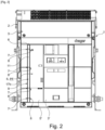
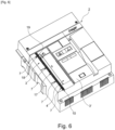
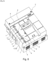
- this configuration of the hinge subassembly 6 with the two axes of rotation A1 and A2 included in a plane P parallel to the external face 3' of the front wall 3 makes it possible to propose a hinge subassembly 6 which has the advantage of being able to be integrated into the geometry of the front wall 3. parallel to the external face 3' in the closed position PF of the access door 5 as illustrated by figures 1 , 2 , 8 And 10 and therefore with a restricted footprint.
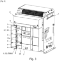
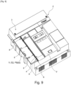
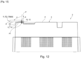
- This configuration also makes it possible to provide an access door 5 which is parallel to the external face 3' in the closed position PF of the access door 5 as illustrated by figures 1 , 2 , 8 And 10 and in the maximum opening position PO as illustrated by the figures 3 , 4 , 9 And 12 .
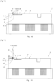
- THE figures 1 , 2 , 8 And 10 show the access door 5 in the closed position PF. More particularly, the Figure 10 illustrates that the movable connection portion 9 is received in the receiving housing 10 and that the plane P is parallel to the external face 3' of the front wall 3 and is contained in the receiving housing 10 or in other words that the first axis of rotation A1 of the first pivot connection 7 and the second axis of rotation A2 of the second pivot connection 8 are contained in the receiving housing 10.
- FIG 11 shows the access door 5 open in the intermediate position PINT.
- the movable connection portion 9 is partially received in the receiving housing 10, the plane P is perpendicular to the external face 3' of the front wall 3 and only the first axis of rotation A1 of the first pivot connection 7 is contained in the receiving housing 10.
- FIGS. 10 and 11 illustrate the first rotational movement of the access door 5 between the closed position PF and the intermediate position PINT.
- the first pivot connection 7 allows the rotation of the movable connection portion 9 and thus of the access door 5 with the first pivot angle ⁇ between 0 and 90 degrees.
- THE figures 11 And 12 illustrate the second rotational movement of the access door 5 between the intermediate position PINT and the maximum opening position PMAX.
- the second pivot connection 8 directly allows the rotation of the access door 5 with the second pivot angle ⁇ ' between 0 and 90 degrees.
- the movable connecting portion 9 is not movable in rotation and remains fixed.
- the movable connecting portion 9 comprises an external surface 11 which is parallel to the plane P and the external surface 11 is parallel to the external face 3' of the front wall 3 in the closed position PF of the access door 5.
- the external surface 11 of the movable connecting portion 9 and the external face 3' of the front wall 3 are parallel in the closed position PF of the access door 5 which improves the integration of the movable connecting portion 9 in the geometry of the front wall 3.
- the external surface 11 of the movable connecting portion 9 is perpendicular to the external face 3' of the front wall 3 in the intermediate position PINT and in the maximum opening position PMAX of the access door 5.
- the front wall 3 comprises a shoulder 12 forming the receiving housing 10 and comprising an edge 13 of depth p located along at least a height h of said opening 4 and the shape of said shoulder 12 is configured to receive the movable connecting portion 9 by shape complementarity.
- a thickness e of the movable connecting portion 9 is equal to the depth p of the shoulder 12.
- the thickness e is for example equal to 4.2 millimeters.
- the external surface 11 of the movable connecting portion 9 and the external face 3' of the front wall 3 can be flush in the closed position PF of the access door 5.
- the width La1 of the shoulder 12 is preferably equal to the width La2 of the movable connecting portion 9.
- the width La2 is for example equal to 9.5 millimeters.
- the length lo1 of the shoulder 12 is preferably equal to the length L of the movable connecting portion 9.
- the external surface 11 of the movable connecting portion 9, the external face 3' of the front wall 3, the external face 5' of the access door 5 can be flush, in the closed position PF of the access door 5. This results in a harmonious integration of the movable connecting portion 9 and the access door 5 in the geometry of the front wall 3.
- said hinge subassembly 6 comprises at least two first cylindrical portions 15 extending longitudinally along the first axis of rotation A1 and being arranged in the receiving housing 10, at least two second cylindrical portions 16 extending longitudinally along the second axis of rotation A2 and being mounted on the access door 5,
- the movable connecting portion 9 comprises a first hinge element 17a and a second hinge element 17b.
- the first hinge element 17a extends longitudinally along the first axis of rotation A1 and the second axis of rotation A2 and contains the plane P and comprises at least two first receiving zones 18 of said at least two first cylindrical portions 15 and at least two second receiving zones 19 of said two second cylindrical portions 16.
- the second hinge element 17b is configured to be assembled to the first hinge element 17a in an assembled position PA by assembly means 20.
- this configuration makes it possible to simplify the design of the movable connecting portion 9 which comprises two parts to be assembled, namely the first hinge element 17a and the second hinge element 17b, to minimize the number of apparent technical functions and to strengthen the resistance to deformations in particular by bending the movable connection portion 9 compared to a design comprising a single part which is less resistant to deformations and which reveals the technical functions.
- the second hinge element 17b makes it possible to cover the first cylindrical portions 15 and second cylindrical portions 16 to form the first and second pivot connections 7, 8 and to cover the technical forms of the first hinge element 17a and in particular the first receiving zones 18 and the second receiving zones 19.
- the assembly means 20 are configured to allow the assembly of the second hinge element 17b with the first hinge element 17a by translational movement of the second hinge element 17b relative to the first hinge element 17a in a translational direction DT parallel to the first axis of rotation A1 and to the second axis of rotation A2.
- this design makes it easier to assemble the first hinge element 17a and the second hinge element 17b together, which has the advantage of being done without the use of tools.
- the assembly means 20 comprise at least one groove 23 provided on the first hinge element 17a and a tongue 24 provided on the second hinge element 17b which extend longitudinally in the translation direction DT so as to allow said translation movement.
- the assembly means 20 comprise at least a first locking member to prevent the withdrawal of the tongue 24 from the groove 23 in a withdrawal direction DR substantially perpendicular to the translation direction DT.
- said first locking member makes it possible to lock the assembly of the first hinge element 17a and the second hinge element 17b together in the assembled position PA.
- the first locking member comprises at least one narrowing segment 25 located on the groove 23 and at least one segment thickening segment 26 located on the tab 24 and the narrowing segment 25 and the thickening segment 26 are aligned in the assembled position PA.
- the first locking member preferably comprises five spaced apart narrowing segments 25 and five spaced apart thickening segments 26. This number of narrowing segments 25 and thickening segments 26 is not limiting.
- the assembly means 20 comprise at least one second locking member for stopping the translation movement in the translation direction DT at the end of the stroke, that is to say when said at least one narrowing segment 25 and said at least one thickening segment 26 are aligned.
- the second locking member comprises a locking hook 40 and a locking notch 41, the locking hook 40 inserting into the locking notch 41 in a locking position PV in which no translational movement DT is possible.
- a first end 42 of the first hinge element 17a comprises said locking notch 41 and a second end 43 of the second hinge element 17b which is arranged opposite the first end 42 of the first hinge element 17a in the assembled position PA and in the locking position PV comprises said locking hook 40 or vice versa.
- first hinge element 17a may be in the form of a first elongated element of first length l1 preferably made of plastic material or equivalent.
- the first assembly face 30 further comprises, on either side of the central groove 23, two first and second receiving grooves 33, 34 provided with a plurality of reinforcing ribs 35.
- the first hinge element 17a comprises four first receiving zones 18 formed by the first receiving groove 33 and the four first receiving notches 18a which make it possible to receive four first cylindrical portions 15.
- the first hinge element 17a comprises four second receiving zones 19 formed by the second receiving groove 34 and the four second receiving notches 19a which make it possible to receive four second cylindrical portions 16.
- the first hinge element 17a further comprises a first external face opposite the first assembly face 30 and which corresponds to the external surface 11 of the movable connecting portion 9.
- the second hinge element 17b may be in the form of a second elongated element of second length l2 preferably made of plastic or equivalent material.
- the second length l2 is equal to the first length 11.
- the second hinge element 17b comprises a second assembly face 36 which comprises another part of the assembly means 20 since it is provided with the tongue 24 which extends in the direction of the second length l2.
- this tongue 24 is arranged centrally.
- the second assembly face 36 further comprises four third receiving notches 22 which are arranged at the third longitudinal edge 37 and spaced from each other.
- the second assembly face 36 further comprises fourth receiving notches 21 which are arranged at the fourth longitudinal edge 38 and spaced from each other.
- the four third receiving notches 22 are arranged opposite the four fourth receiving notches 21.
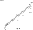
- the second hinge element 17b further comprises a second outer face 39 opposite the second assembly face 36 and which is visible for example at figure 16 .
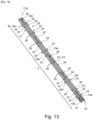
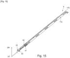
- FIG. 15 illustrates the assembly of the first hinge element 17a and the second hinge element 17b.
- FIG 16 illustrates the movable connecting portion 9 in the assembled position PA.
- the first hinge element 17a and the second hinge element 17b whose second length l2 is equal to the first length l1 are aligned and facing each other by the first assembly face 30 and the second assembly face 36.
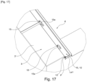
- FIG. 17 illustrates that the first cylindrical portions 15 are connected to the edge 13 of the shoulder 12 by a first connecting part 15a projecting perpendicular to the edge 13.
- the subassembly formed by the first cylindrical portion 15 and the first connecting part 15a has a general T or L shape.
- FIG. 18 illustrates that the second cylindrical portions 16 are connected to the access door 5 by a second connecting part 16a projecting perpendicularly from the edge 5a of the access door 5.
- the subassembly formed by the second cylindrical portion 16 and the second connecting part 16a has a general T or L shape.
- the first cylindrical portions 15 are received in the first receiving groove 33 and the first connecting part 15a is received in the first receiving notch 18a.
- the second cylindrical portions 16 are received in the second receiving groove 34 and the second connecting part 16a is received in the second receiving notch 19a.
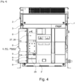
- the electrical protection apparatus further comprises an electronic trip device 27 mounted removably from the chassis 1 and comprising a housing 28 whose front face 29 is made accessible by said opening 4 in the open position PO of the access door 5 and is covered by the access door 5 in the closed position PF.
- an electronic trip device 27 mounted removably from the chassis 1 and comprising a housing 28 whose front face 29 is made accessible by said opening 4 in the open position PO of the access door 5 and is covered by the access door 5 in the closed position PF.
- the protective electrical apparatus is a circuit breaker, for example an air circuit breaker.
- the invention also relates to a method of assembling the access door 5 on the front face 2.
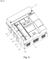
- THE figures 5 to 8 illustrate a method of assembling the access door 5 on the front face 2 according to the invention.
- This assembly process has the advantage of being done without the use of tools.
- the assembly is carried out by translational movement of the second hinge element 17b relative to the first hinge element 17a in the translation direction DT parallel to the first axis of rotation A1 and to the second axis of rotation A2, the groove 23 formed on the first hinge element 17a slides in the tab 24 formed on the second hinge element 17b in the translation direction DT.
- the first hinge element 17a and the second hinge element 17b whose second length l2 is equal to the first length l1 are aligned and opposite each other by the first assembly face 30 and the second assembly face 36.
Landscapes
- Engineering & Computer Science (AREA)
- Mechanical Engineering (AREA)
- Casings For Electric Apparatus (AREA)
- Patch Boards (AREA)
Claims (14)
- Frontseite (2) für ein elektrisches Schutzgerät, umfassend mindestens:- eine vordere Wand (3), die eine Öffnung (4) umfasst,- eine Zugangstür (5), die durch eine Scharnierbaugruppe (6) relativ zu der vorderen Wand (3) schwenkbar montiert ist und dazu ausgestaltet ist, die Öffnung (4) in einer geöffneten Stellung (PF) zu verschließen und in einer geöffneten Stellung (PO) Zugang zu der Öffnung (4) zu gewähren,wobei die Scharnierbaugruppe (6) umfasst:- eine erste Schwenkverbindung (7), um eine erste Drehbewegung der Zugangstür (5) relativ zu der vorderen Wand (3) um eine erste Drehachse (A1) zu ermöglichen, und- eine zweite Schwenkverbindung (8), um eine zweite Drehbewegung der Zugangstür (5) relativ zu der vorderen Wand (3) um eine zweite Drehachse (A2) zu ermöglichen,
die erste Drehachse (A1) und die zweite Drehachse (A2) sind parallel zueinander und in einer Ebene (P) um einen Abstand (d) beabstandet,- die Scharnierbaugruppe (6) umfasst einen beweglichen Verbindungsabschnitt (9),- die erste Schwenkverbindung (7) verbindet die vordere Wand (3) und den beweglichen Verbindungsabschnitt (9) und ist dazu ausgestaltet, die erste Drehbewegung um die erste Drehachse (A1) zu ermöglichen, deren erster Schwenkwinkel (α) zwischen 0 Grad und 90 Grad zwischen der geschlossenen Stellung (PF) und einer Zwischenstellung (PINT) der Zugangstür (5) beträgt,- die zweite Schwenkverbindung (8) verbindet den beweglichen Verbindungsabschnitt (9) und die Zugangstür (5) und ist dazu ausgestaltet, die zweite Drehbewegung um die zweite Drehachse (A2) zu ermöglichen, deren zweiter Schwenkwinkel (α') zwischen 0 Grad und 90 Grad zwischen der Zwischenstellung (PINT) und einer maximalen Stellung (PMAX) der Zugangstür (5) beträgt, und- die vordere Wand (3) umfasst einen Aufnahmesitz (10), der dazu ausgestaltet ist, den beweglichen Verbindungsabschnitt (9) mindestens teilweise aufzunehmen, und- in der geschlossenen Stellung (PF) der Zugangstür (5) ist die Ebene (P) parallel zu einer Außenseite (3') der vorderen Wand (3) und in dem Aufnahmesitz (10) enthalten,- in der maximalen Öffnungsstellung (PMAX) der Zugangstür (5) ist die Ebene (P) senkrecht zu der Außenseite (3') der vorderen Wand (3); die Frontseite (2) ist dadurch gekennzeichnet, dass:- die vordere Wand (3) eine Schulter (12) umfasst, die den Aufnahmesitz (10) bildet und einen Rand (13) mit der Tiefe (p) umfasst, der entlang mindestens einer Höhe (h) der Öffnung (4) gelegen ist, und- die Form der Schulter (12) dazu ausgestaltet ist, den beweglichen Verbindungsabschnitt (9) durch Formschluss aufzunehmen. - Frontseite nach Anspruch 1, dadurch gekennzeichnet, dass der bewegliche Verbindungsabschnitt (9) eine Außenfläche (11) umfasst, die parallel zu der Ebene (P) ist, und dass die Außenfläche (11) parallel zu der Außenseite (3') der vorderen Wand (3) in der geschlossenen Stellung (PF) der Zugangstür (5) ist.
- Frontseite nach Anspruch 2, dadurch gekennzeichnet, dass die Außenfläche (11) des beweglichen Verbindungsabschnitts (9) senkrecht zu der Außenseite (3') der vorderen Wand (3) in der Zwischenstellung (PINT) und in der maximalen Öffnungsstellung (PMAX) der Zugangstür (5) ist.
- Frontseite nach einem der Ansprüche 1 bis 3, dadurch gekennzeichnet, dass eine Dicke (e) des beweglichen Verbindungsabschnitts (9) gleich der Tiefe (p) der Schulter (12) ist.
- Frontseite nach einem der Ansprüche 1 bis 4, dadurch gekennzeichnet, dass der Rand (13) der Schulter (12) einen ersten Stoppanschlag (14) bildet, der dazu eingerichtet ist, die erste Drehbewegung auf einen ersten maximalen Schwenkwinkel (α) von 90 Grad zu begrenzen.
- Frontseite nach einem der Ansprüche 1 bis 5, dadurch gekennzeichnet, dass die Scharnierbaugruppe (6) mindestens zwei erste zylindrische Abschnitte (15) umfasst, die sich längs entlang der ersten Drehachse (A1) erstrecken und in dem Aufnahmesitz (10) angeordnet sind, wobei sich mindestens zwei zweite zylindrische Abschnitte (16) längs entlang der zweiten Drehachse (A2) erstrecken und an der Zugangstür (5) angebracht sind, der bewegliche Verbindungsabschnitt (9) ein erstes Scharnierelement (17a) und ein zweites Scharnierelement (17b) umfasst, wobei sich das erste Scharnierelement (17a) längs entlang der ersten Drehachse (A1) und der zweiten Drehachse (A2) erstreckt und die Ebene (P) enthält und mindestens zwei erste Aufnahmebereiche (18) für die mindestens zwei ersten zylindrischen Abschnitte (15) und mindestens zwei zweite Aufnahmebereiche (19) für die zwei zweiten zylindrischen Abschnitte (16) umfasst, wobei das zweite Scharnierelement (17b) dazu ausgestaltet ist, an das erste Scharnierelement (17a) in einer gefügten Stellung (PA) durch Fügemittel (20) gefügt zu sein.
- Frontseite nach Anspruch 6, dadurch gekennzeichnet, dass die Fügemittel (20) dazu ausgestaltet sind, das Fügen des zweiten Scharnierelements (17b) mit dem ersten Scharnierelement (17a) durch Translationsbewegung des zweiten Scharnierelements (17b) relativ zu dem ersten Scharnierelement (17a) entlang einer Translationsrichtung (DT) parallel zu der ersten Drehachse (A1) und der zweiten Drehachse (A2) zu ermöglichen.
- Frontseite nach Anspruch 7, dadurch gekennzeichnet, dass die Fügemittel (20) mindestens eine an dem ersten Scharnierelement (17a) ausgebildete Nut (23) und eine an dem zweiten Scharnierelement (17b) ausgebildete Feder (24) beinhalten, die sich längs entlang der Translationsrichtung (DT) erstrecken, so dass sie die Translationsbewegung ermöglichen.
- Frontseite nach Anspruch 8, dadurch gekennzeichnet, dass die Fügemittel (20) mindestens ein erstes Verriegelungsorgan beinhalten, um das Herausziehen der Feder (24) aus der Nut (23) in einer Ausziehrichtung (DR) zu verhindern, die im Wesentlichen senkrecht zu der Translationsrichtung (DT) ist.
- Frontseite nach Anspruch 9, dadurch gekennzeichnet, dass das erste Verriegelungsorgan mindestens ein an der Nut (23) gelegenes Verengungssegment (25) und mindestens ein an der Feder (24) gelegenes Verdickungssegment (26) umfasst und dass das Verengungssegment (25) und das Verdickungssegment (26) in der gefügten Stellung (PA) fluchten.
- Elektrisches Schutzgerät, umfassend mindestens:- einen Rahmen (1),- eine Frontseite (2), die von dem Rahmen (1) abnehmbar angebracht ist, wobei das elektrische Schutzgerät dadurch gekennzeichnet ist, dass es eine Frontseite (2) nach einem der Ansprüche 1 bis 10 umfasst.
- Elektrisches Schutzgerät nach Anspruch 11, dadurch gekennzeichnet, dass es ferner einen elektronischen Auslöser (27) umfasst, der von dem Rahmen (1) abnehmbar angebracht ist und ein Gehäuse (28) umfasst, dessen Frontwand (29) durch die Öffnung (4) in der geöffneten Stellung (PO) der Zugangstür (5) zugänglich gemacht wird und durch die Zugangstür (5) in der geschlossenen Stellung (PF) abgedeckt wird.
- Verfahren zum Fügen der Zugangstür (5) an die Frontseite (2), dadurch gekennzeichnet, dass die Frontseite (2) einem der Ansprüche 6 bis 10 entspricht, wobei das Verfahren zum Fügen umfasst:einen ersten Schritt des Bereitstellens der Frontseite (2),einen zweiten Schritt des Fügens des ersten Scharnierelements (17a) mit der Frontseite (2), bei dem das erste Scharnierelement (17a) durch Fügen der mindestens zwei zylindrischen Abschnitte (15) und der mindestens zwei ersten Aufnahmebereiche (18) untereinander an die Frontseite (2) gefügt wird,einen dritten Schritt des Fügens der Zugangstür (5) mit dem ersten Scharnierelement (17a), bei dem die Zugangstür (5) durch Fügen der mindestens zwei zweiten zylindrischen Abschnitte (16) und der mindestens zwei zweiten Aufnahmebereiche (19) untereinander mit dem ersten Scharnierelement (17a) gefügt wird,einen vierten Schritt des Fügens des zweiten Scharnierelements (17b) mit dem ersten Scharnierelement (17a), bei dem das erste Scharnierelement (17a) und das zweite Scharnierelement (17b) durch Fügen der Fügemittel (20) untereinander gefügt werden.
- Verfahren zur Fügen nach Anspruch 13, dadurch gekennzeichnet, dass bei dem vierten Schritt des Fügens das Fügen durch eine Translationsbewegung des zweiten Scharnierelements (17b) relativ zu dem ersten Scharnierelement (17a) entlang der Translationsrichtung (DT) parallel zu der ersten Drehachse (A1) und zu der zweiten Drehachse (A2) erfolgt und die an dem ersten Scharnierelement (17a) ausgebildete Nut (23) entlang der Translationsrichtung (DT) in die an dem zweiten Scharnierelement (17b) ausgebildete Feder (24) gleitet.
Applications Claiming Priority (1)
| Application Number | Priority Date | Filing Date | Title |
|---|---|---|---|
| FR2209799A FR3140239B1 (fr) | 2022-09-27 | 2022-09-27 | Face avant pour un appareillage électrique de protection et appareil électrique de protection |
Publications (2)
| Publication Number | Publication Date |
|---|---|
| EP4345857A1 EP4345857A1 (de) | 2024-04-03 |
| EP4345857B1 true EP4345857B1 (de) | 2025-06-04 |
Family
ID=84370514
Family Applications (1)
| Application Number | Title | Priority Date | Filing Date |
|---|---|---|---|
| EP23199773.5A Active EP4345857B1 (de) | 2022-09-27 | 2023-09-26 | Frontseite für ein elektrisches schutzgerät und elektrisches schutzgerät |
Country Status (3)
| Country | Link |
|---|---|
| EP (1) | EP4345857B1 (de) |
| CN (1) | CN117790247A (de) |
| FR (1) | FR3140239B1 (de) |
Family Cites Families (3)
| Publication number | Priority date | Publication date | Assignee | Title |
|---|---|---|---|---|
| DE6804119U (de) * | 1968-10-26 | 1969-01-30 | Karl W Lotz | Scharnier fuer die schwenkbare befestigung von tueren |
| JP2978129B2 (ja) * | 1997-02-21 | 1999-11-15 | タキゲン製造株式会社 | 2軸型裏蝶番 |
| CN105756490A (zh) * | 2016-04-27 | 2016-07-13 | 成都尤立科电器有限公司 | 配电箱面板 |
-
2022
- 2022-09-27 FR FR2209799A patent/FR3140239B1/fr active Active
-
2023
- 2023-09-26 EP EP23199773.5A patent/EP4345857B1/de active Active
- 2023-09-27 CN CN202311261043.0A patent/CN117790247A/zh active Pending
Also Published As
| Publication number | Publication date |
|---|---|
| FR3140239A1 (fr) | 2024-03-29 |
| CN117790247A (zh) | 2024-03-29 |
| EP4345857A1 (de) | 2024-04-03 |
| FR3140239B1 (fr) | 2025-02-14 |
Similar Documents
| Publication | Publication Date | Title |
|---|---|---|
| EP2456024B1 (de) | Stromsteckdose mit Verschlussvorrichtung | |
| EP1604085B1 (de) | Schlüsselgehäuse | |
| EP3393294B1 (de) | Gepäckstück mit einer vorrichtung zum verriegeln eines reissverschlusses | |
| FR2774221A1 (fr) | Boitier a encastrer dans une quelconque paroi, notamment pour appareil electrique | |
| EP2456021B1 (de) | Stromsteckdose mit seitlichen verschiebbaren Balken | |
| EP4345857B1 (de) | Frontseite für ein elektrisches schutzgerät und elektrisches schutzgerät | |
| EP3840151B1 (de) | Schaltkasten und zugehörige elektrische ausrüstung | |
| EP2926535B1 (de) | Anschlussgehäuse | |
| EP3840152B1 (de) | Gerätehalterung für die montage in eine wand geringer dicke, und gerätemodul, das eine solche hatlerung umfasst | |
| EP2784885B1 (de) | Abnehmbare Element für modulares elektrisches Gerät mit schwenkbarem Griff | |
| EP1139537A1 (de) | Einbaudose für elektrisches Gerät zur Montage entlang einem Kabelkanal | |
| EP4258499A2 (de) | Abgedichtetes elektrisches gerät | |
| EP1865579A1 (de) | Selbstabisolierende Verbindungsanschluss und elektrisches Gerät mit einem solchen Anschluss | |
| FR2936656A1 (fr) | Borne de connexion electrique automatique | |
| FR3115483A1 (fr) | Couteau a lame retractable coulissante | |
| EP2539722B1 (de) | Gehäuse mit mitteln zum befestigen auf einer trägerplatte | |
| EP2824785B1 (de) | Gelenkeinheit eines Gehäuses für Elektrogerät, und Bodendose, die eine solche Einheit umfasst | |
| EP3686058B1 (de) | Abdeckvorrichtung eines kofferraumfachs eines kraftfahrzeugs | |
| FR2901068A1 (fr) | Panneau support d'appareillage electrique | |
| FR3001835A1 (fr) | Boite d'encastrement en deux parties | |
| EP3581739B1 (de) | Schutzvorrichtung für entriegelungsmechanismus eines türschlosses vom typ mit flächenbündigem griff | |
| WO2025032114A1 (fr) | Volet battant a panneau pivotant | |
| EP3073304B1 (de) | Lichtleitfaser-steckverbinder | |
| EP4625465A1 (de) | Steuereinheit für einen elektrischen leistungsschalter und zugehöriger elektrischer leistungsschalter | |
| EP4346036A1 (de) | Schutzzubehör für die tür eines schaltschranks, tür und schaltschrank mit solchem schutzzubehör |
Legal Events
| Date | Code | Title | Description |
|---|---|---|---|
| PUAI | Public reference made under article 153(3) epc to a published international application that has entered the european phase |
Free format text: ORIGINAL CODE: 0009012 |
|
| STAA | Information on the status of an ep patent application or granted ep patent |
Free format text: STATUS: THE APPLICATION HAS BEEN PUBLISHED |
|
| AK | Designated contracting states |
Kind code of ref document: A1 Designated state(s): AL AT BE BG CH CY CZ DE DK EE ES FI FR GB GR HR HU IE IS IT LI LT LU LV MC ME MK MT NL NO PL PT RO RS SE SI SK SM TR |
|
| STAA | Information on the status of an ep patent application or granted ep patent |
Free format text: STATUS: REQUEST FOR EXAMINATION WAS MADE |
|
| 17P | Request for examination filed |
Effective date: 20240926 |
|
| RBV | Designated contracting states (corrected) |
Designated state(s): AL AT BE BG CH CY CZ DE DK EE ES FI FR GB GR HR HU IE IS IT LI LT LU LV MC ME MK MT NL NO PL PT RO RS SE SI SK SM TR |
|
| GRAP | Despatch of communication of intention to grant a patent |
Free format text: ORIGINAL CODE: EPIDOSNIGR1 |
|
| STAA | Information on the status of an ep patent application or granted ep patent |
Free format text: STATUS: GRANT OF PATENT IS INTENDED |
|
| INTG | Intention to grant announced |
Effective date: 20250107 |
|
| GRAS | Grant fee paid |
Free format text: ORIGINAL CODE: EPIDOSNIGR3 |
|
| GRAA | (expected) grant |
Free format text: ORIGINAL CODE: 0009210 |
|
| STAA | Information on the status of an ep patent application or granted ep patent |
Free format text: STATUS: THE PATENT HAS BEEN GRANTED |
|
| AK | Designated contracting states |
Kind code of ref document: B1 Designated state(s): AL AT BE BG CH CY CZ DE DK EE ES FI FR GB GR HR HU IE IS IT LI LT LU LV MC ME MK MT NL NO PL PT RO RS SE SI SK SM TR |
|
| REG | Reference to a national code |
Ref country code: GB Ref legal event code: FG4D Free format text: NOT ENGLISH |
|
| REG | Reference to a national code |
Ref country code: CH Ref legal event code: EP |
|
| REG | Reference to a national code |
Ref country code: DE Ref legal event code: R096 Ref document number: 602023003827 Country of ref document: DE |
|
| REG | Reference to a national code |
Ref country code: IE Ref legal event code: FG4D Free format text: LANGUAGE OF EP DOCUMENT: FRENCH |
|
| REG | Reference to a national code |
Ref country code: NL Ref legal event code: MP Effective date: 20250604 |
|
| PG25 | Lapsed in a contracting state [announced via postgrant information from national office to epo] |
Ref country code: ES Free format text: LAPSE BECAUSE OF FAILURE TO SUBMIT A TRANSLATION OF THE DESCRIPTION OR TO PAY THE FEE WITHIN THE PRESCRIBED TIME-LIMIT Effective date: 20250604 Ref country code: FI Free format text: LAPSE BECAUSE OF FAILURE TO SUBMIT A TRANSLATION OF THE DESCRIPTION OR TO PAY THE FEE WITHIN THE PRESCRIBED TIME-LIMIT Effective date: 20250604 |
|
| PGFP | Annual fee paid to national office [announced via postgrant information from national office to epo] |
Ref country code: DE Payment date: 20250929 Year of fee payment: 3 |
|
| REG | Reference to a national code |
Ref country code: LT Ref legal event code: MG9D |
|
| PG25 | Lapsed in a contracting state [announced via postgrant information from national office to epo] |
Ref country code: GR Free format text: LAPSE BECAUSE OF FAILURE TO SUBMIT A TRANSLATION OF THE DESCRIPTION OR TO PAY THE FEE WITHIN THE PRESCRIBED TIME-LIMIT Effective date: 20250905 Ref country code: NO Free format text: LAPSE BECAUSE OF FAILURE TO SUBMIT A TRANSLATION OF THE DESCRIPTION OR TO PAY THE FEE WITHIN THE PRESCRIBED TIME-LIMIT Effective date: 20250904 |
|
| PG25 | Lapsed in a contracting state [announced via postgrant information from national office to epo] |
Ref country code: PL Free format text: LAPSE BECAUSE OF FAILURE TO SUBMIT A TRANSLATION OF THE DESCRIPTION OR TO PAY THE FEE WITHIN THE PRESCRIBED TIME-LIMIT Effective date: 20250604 |
|
| PG25 | Lapsed in a contracting state [announced via postgrant information from national office to epo] |
Ref country code: BG Free format text: LAPSE BECAUSE OF FAILURE TO SUBMIT A TRANSLATION OF THE DESCRIPTION OR TO PAY THE FEE WITHIN THE PRESCRIBED TIME-LIMIT Effective date: 20250604 |
|
| PG25 | Lapsed in a contracting state [announced via postgrant information from national office to epo] |
Ref country code: HR Free format text: LAPSE BECAUSE OF FAILURE TO SUBMIT A TRANSLATION OF THE DESCRIPTION OR TO PAY THE FEE WITHIN THE PRESCRIBED TIME-LIMIT Effective date: 20250604 |
|
| PGFP | Annual fee paid to national office [announced via postgrant information from national office to epo] |
Ref country code: FR Payment date: 20250925 Year of fee payment: 3 Ref country code: AT Payment date: 20251020 Year of fee payment: 3 |
|
| PG25 | Lapsed in a contracting state [announced via postgrant information from national office to epo] |
Ref country code: RS Free format text: LAPSE BECAUSE OF FAILURE TO SUBMIT A TRANSLATION OF THE DESCRIPTION OR TO PAY THE FEE WITHIN THE PRESCRIBED TIME-LIMIT Effective date: 20250904 |
|
| PG25 | Lapsed in a contracting state [announced via postgrant information from national office to epo] |
Ref country code: LV Free format text: LAPSE BECAUSE OF FAILURE TO SUBMIT A TRANSLATION OF THE DESCRIPTION OR TO PAY THE FEE WITHIN THE PRESCRIBED TIME-LIMIT Effective date: 20250604 |
|
| PG25 | Lapsed in a contracting state [announced via postgrant information from national office to epo] |
Ref country code: NL Free format text: LAPSE BECAUSE OF FAILURE TO SUBMIT A TRANSLATION OF THE DESCRIPTION OR TO PAY THE FEE WITHIN THE PRESCRIBED TIME-LIMIT Effective date: 20250604 |
|
| PG25 | Lapsed in a contracting state [announced via postgrant information from national office to epo] |
Ref country code: PT Free format text: LAPSE BECAUSE OF FAILURE TO SUBMIT A TRANSLATION OF THE DESCRIPTION OR TO PAY THE FEE WITHIN THE PRESCRIBED TIME-LIMIT Effective date: 20251006 |
|
| REG | Reference to a national code |
Ref country code: AT Ref legal event code: MK05 Ref document number: 1801224 Country of ref document: AT Kind code of ref document: T Effective date: 20250604 |
|
| PG25 | Lapsed in a contracting state [announced via postgrant information from national office to epo] |
Ref country code: IS Free format text: LAPSE BECAUSE OF FAILURE TO SUBMIT A TRANSLATION OF THE DESCRIPTION OR TO PAY THE FEE WITHIN THE PRESCRIBED TIME-LIMIT Effective date: 20251004 |
|
| PG25 | Lapsed in a contracting state [announced via postgrant information from national office to epo] |
Ref country code: SM Free format text: LAPSE BECAUSE OF FAILURE TO SUBMIT A TRANSLATION OF THE DESCRIPTION OR TO PAY THE FEE WITHIN THE PRESCRIBED TIME-LIMIT Effective date: 20250604 Ref country code: AT Free format text: LAPSE BECAUSE OF FAILURE TO SUBMIT A TRANSLATION OF THE DESCRIPTION OR TO PAY THE FEE WITHIN THE PRESCRIBED TIME-LIMIT Effective date: 20250604 |
|
| PG25 | Lapsed in a contracting state [announced via postgrant information from national office to epo] |
Ref country code: CZ Free format text: LAPSE BECAUSE OF FAILURE TO SUBMIT A TRANSLATION OF THE DESCRIPTION OR TO PAY THE FEE WITHIN THE PRESCRIBED TIME-LIMIT Effective date: 20250604 |
|
| PG25 | Lapsed in a contracting state [announced via postgrant information from national office to epo] |
Ref country code: EE Free format text: LAPSE BECAUSE OF FAILURE TO SUBMIT A TRANSLATION OF THE DESCRIPTION OR TO PAY THE FEE WITHIN THE PRESCRIBED TIME-LIMIT Effective date: 20250604 |
|
| PG25 | Lapsed in a contracting state [announced via postgrant information from national office to epo] |
Ref country code: SK Free format text: LAPSE BECAUSE OF FAILURE TO SUBMIT A TRANSLATION OF THE DESCRIPTION OR TO PAY THE FEE WITHIN THE PRESCRIBED TIME-LIMIT Effective date: 20250604 |
|
| PG25 | Lapsed in a contracting state [announced via postgrant information from national office to epo] |
Ref country code: IT Free format text: LAPSE BECAUSE OF FAILURE TO SUBMIT A TRANSLATION OF THE DESCRIPTION OR TO PAY THE FEE WITHIN THE PRESCRIBED TIME-LIMIT Effective date: 20250604 |
|
| PG25 | Lapsed in a contracting state [announced via postgrant information from national office to epo] |
Ref country code: RO Free format text: LAPSE BECAUSE OF FAILURE TO SUBMIT A TRANSLATION OF THE DESCRIPTION OR TO PAY THE FEE WITHIN THE PRESCRIBED TIME-LIMIT Effective date: 20250604 |