EP3073304B1 - Lichtleitfaser-steckverbinder - Google Patents
Lichtleitfaser-steckverbinder Download PDFInfo
- Publication number
- EP3073304B1 EP3073304B1 EP16162093.5A EP16162093A EP3073304B1 EP 3073304 B1 EP3073304 B1 EP 3073304B1 EP 16162093 A EP16162093 A EP 16162093A EP 3073304 B1 EP3073304 B1 EP 3073304B1
- Authority
- EP
- European Patent Office
- Prior art keywords
- plug
- connector
- edge
- extension
- box
- Prior art date
- Legal status (The legal status is an assumption and is not a legal conclusion. Google has not performed a legal analysis and makes no representation as to the accuracy of the status listed.)
- Active
Links
Images

Classifications
-
- G—PHYSICS
- G02—OPTICS
- G02B—OPTICAL ELEMENTS, SYSTEMS OR APPARATUS
- G02B6/00—Light guides; Structural details of arrangements comprising light guides and other optical elements, e.g. couplings
- G02B6/24—Coupling light guides
- G02B6/36—Mechanical coupling means
- G02B6/38—Mechanical coupling means having fibre to fibre mating means
- G02B6/3807—Dismountable connectors, i.e. comprising plugs
- G02B6/3833—Details of mounting fibres in ferrules; Assembly methods; Manufacture
- G02B6/3847—Details of mounting fibres in ferrules; Assembly methods; Manufacture with means preventing fibre end damage, e.g. recessed fibre surfaces
- G02B6/3849—Details of mounting fibres in ferrules; Assembly methods; Manufacture with means preventing fibre end damage, e.g. recessed fibre surfaces using mechanical protective elements, e.g. caps, hoods, sealing membranes
-
- G—PHYSICS
- G02—OPTICS
- G02B—OPTICAL ELEMENTS, SYSTEMS OR APPARATUS
- G02B6/00—Light guides; Structural details of arrangements comprising light guides and other optical elements, e.g. couplings
- G02B6/24—Coupling light guides
- G02B6/36—Mechanical coupling means
- G02B6/38—Mechanical coupling means having fibre to fibre mating means
- G02B6/3807—Dismountable connectors, i.e. comprising plugs
- G02B6/381—Dismountable connectors, i.e. comprising plugs of the ferrule type, e.g. fibre ends embedded in ferrules, connecting a pair of fibres
- G02B6/3825—Dismountable connectors, i.e. comprising plugs of the ferrule type, e.g. fibre ends embedded in ferrules, connecting a pair of fibres with an intermediate part, e.g. adapter, receptacle, linking two plugs
-
- G—PHYSICS
- G02—OPTICS
- G02B—OPTICAL ELEMENTS, SYSTEMS OR APPARATUS
- G02B6/00—Light guides; Structural details of arrangements comprising light guides and other optical elements, e.g. couplings
- G02B6/24—Coupling light guides
- G02B6/36—Mechanical coupling means
- G02B6/38—Mechanical coupling means having fibre to fibre mating means
- G02B6/3807—Dismountable connectors, i.e. comprising plugs
- G02B6/389—Dismountable connectors, i.e. comprising plugs characterised by the method of fastening connecting plugs and sockets, e.g. screw- or nut-lock, snap-in, bayonet type
- G02B6/3893—Push-pull type, e.g. snap-in, push-on
Definitions
- the present invention relates to an optical fiber connector.
- connection of an optical fiber involves avoiding any contact of the end of the optical fiber with any dirt, failing which the connection is bad, or not done.
- connection box that is to say the part of the connector delimiting the connection cavity
- plug also called a “ferrule”
- the connection box that is to say the part of the connector delimiting the connection cavity
- plug also called a “ferrule”
- pivoting or tilting flap which must be lifted when the connection is made.
- a similar type of connector includes means for opening the shutter (s) automatically upon connection.
- connectors of this type have the drawback of having structures that are complex and expensive to manufacture.
- the connector housing comprises a first edge delimiting the opening of said connection cavity, at which the pivoting flap is mounted, inclined lateral edges, straight or concave, laterally delimiting said opening, and a second edge, opposite to said first edge , set back from this first edge; the end of the optical fiber protrudes from the end of the plug and is surrounded by a protective tubular casing forming a connection end.
- IEC international standard
- a connector of this type is advantageous in that it allows, thanks to the shape of the aforementioned edges delimiting the opening of the cavity, an inclined engagement of the plug, that is to say an engagement during which the The longitudinal axis of the plug is not parallel to the longitudinal axis of the cavity.
- Such an inclined engagement can in fact be made necessary when the space involved by a focused engagement of the plug is lacking.
- This connector also has a significantly simpler structure than that of the previous type of connector. However, it has the disadvantage of not ensure perfect protection of the optical fiber against dirt during connection.
- Patent Application Publication No. WO 2014/107922 A1 describes a connector whose flap 22, as seen on the figure 2 of this document, is flat and comprises a central rib 221 flat.
- the connector according to this document does not make it possible to solve the aforementioned drawback.
- the present invention aims to remedy this drawback by providing a connector conforming to said "SC" standard, ensuring perfect protection of the end of the optical fiber during connection while having a structure that remains relatively simple.
- the connector concerned comprises, in a manner known per se, a connection box defining an elongated connection cavity and a plug intended to be engaged in this connection cavity;
- the housing comprises a first edge delimiting the opening of said connection cavity, at the level of which is mounted a pivoting flap, inclined side edges, straight or concave, laterally delimiting said opening, and a second edge delimiting the opening, opposite to said first edge and set back from the latter;
- the end of the optical fiber protrudes from the end of the body of the plug and is surrounded by a protective tubular envelope, forming a connection end.
- width refers to the dimension presented by said main part of the shutter in a direction parallel to the pivot axis of the shutter.
- the plug could be presented vis-à-vis the housing at any inclination, making it possible, in a wide range of inclinations, to contact the end. optical fiber with the shutter, and thus inducing a significant risk of soiling of this end; the inventor has therefore designed to provide said extension, which renders inoperative a presentation of the card at a significant inclination, greater than about 35 degrees, given that beyond this angle of inclination, said tubular protective casing or the body of the plug meets the housing below the pivot axis of the shutter; said extension also imposes, so that the insertion of the plug into the housing is possible, a maximum angle of inclination of the plug, of the order of about thirty degrees, below which the body of the plug comes press against the shutter above the pivot axis of this shutter and therefore allows this shutter to be pivoted with a view to inserting the plug into the connection cavity.
- the combination of the already sufficiently reduced inclination of the plug and the concave shape of the shutter means that it is the tubular casing surrounding the end of the optical fiber that comes into contact with the shutter, not this end itself.
- the connector according to the present invention ensures perfect protection of the end of the optical fiber during connection while having a structure according to the “SC” standard, remaining relatively simple.
- the flap comprises, at its aforementioned base marginal part, a portion of convex shape extending over a height of the order of one tenth or one fifth of the total height of the flap.
- the term “height” refers to the dimension that the shutter has in a direction going from the wall of the box forming said first edge to the wall of the box forming said second edge, perpendicular to these walls.
- This portion of convex shape promotes the rapid removal of the shutter when the tubular casing is supported against this shutter, then that of the body of the plug, and therefore contributes to reducing the risk of soiling the end. fiber optic through the shutter.
- the plug comprises a boss on its side intended to be located on the same side as said extension, and this extension, as well as the housing, comprises a longitudinal groove in which said boss is intended to be engaged and to slide during the inserting the plug into the cavity.
- This boss is placed in front of the entry of the groove when the plug is presented in front of the housing, and more or less guides the plug during the progressive alignment of the longitudinal axis of the plug with the longitudinal axis of the cavity ; when this alignment is done, the boss engages in said groove.
- the boss advantageously has an elongated shape, which promotes guiding of the plug during the insertion of the boss in the groove.
- said extension has, at its free edge, a width less than the width that it has at said second side of the housing and has curved and convex lateral edges.
- This form of the extension proves to favor the positioning of the plug in the axis of the cavity when this plug is presented laterally with respect to the housing.
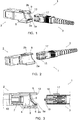
- the figures 1 to 3 show an optical fiber connector 1 comprising a connection box 2 and a plug 3 intended to be engaged in an elongated connection cavity 4 defined by the box 2.
- This connector 1 conforms to the international standard (IEC) called "SC”.
- the opening of the cavity 4 is delimited by a first edge 2a (located in the lower position in the figures), by concave lateral edges and by a second edge 2b, opposite to said first edge 2a, located behind this first edge 2a .
- the housing 2 comprises a flap 5 mounted to pivot on it, at the level of the edge 2a, which is biased by a spring 6 in a normal closed position of the cavity 4, shown in the figures. figures 1 to 3 .
- the flap 5 protects the end of the optical fiber 10 connected to the housing 2, which opens into the bottom of a connection end piece 7 located in the cavity 4.
- the shutter 5 is completely retracted into a receiving housing 8 formed by the housing 2, as visible on the figure 7 .
- the shutter 5 presents, when viewed according to the figure 3 , that is to say in a lateral direction parallel to its pivot axis, a curved shape on a main part extending over most of its height.
- the concavity of this curved main part extends over the entire width of said main part (visible on the figure 1 ) and is turned on the outside of the housing.
- the concavity of this main part bends close to the pivot axis of the shutter, to form, at the level of a base marginal part 5a close to the pivot axis, a reverse curvature, therefore convex on the side exterior of the shutter, extending over a height of the order of one tenth or one fifth of the total height of the shutter 5.
- the shutter 5 is therefore arranged on the housing 2 such that the concavity of its main part is turned on the outside of the housing 2, and that the convexity of its marginal portion 5a faces the outside of this housing.
- the housing 2 also comprises an extension 9 projecting from the edge 2b in a direction parallel to the longitudinal axis of the cavity 4. As shown in particular by figure 3 , this extension 9 projects over a distance such that its free edge is located beyond the pivot axis of the shutter 5. In the example shown, this free edge is substantially in line with the end face of the housing 2 forming the edge 2a.
- the extension 9 has, at its free edge, a width less than the width that it has at the edge 2b of the housing 2, and it has curved and convex side edges. It defines, like the housing 2 at the level of the cavity 4, a longitudinal groove 13.
- the plug 3 does not include a shutter, as results from the "SC" standard, but has a tubular envelope 15 surrounding the optical fiber 16, which protrudes from the end of the body of this plug.
- This tubular casing 15 forms a connection end piece, able to come into engagement with the end piece 7, as visible on the figure. figure 7 , and its peripheral end edge is chamfered in order to promote this engagement.
- the plug 3 also comprises an elongated boss 17 on its side intended to be located on the same side as the extension 9, this boss 17 being intended to be engaged and to slide in the groove 13 during the insertion of the plug 3 in cavity 4.
- the relative positions of the free edge of the extension 9 and of the axis of the shutter 5 are such that the extension 9 renders inoperative a presentation of the sheet 3 at a significant inclination, greater than the inclination of approximately 35 degrees shown (this inclination is the acute angle formed by the longitudinal axis of the plug 3 and by the longitudinal axis of the cavity 4). In fact, beyond this angle of 35 degrees, the tubular casing 15 or the body of the plug 3 meets the housing 2 below the pivot axis of the shutter 5. Such an inclination of the plug 3 will be therefore excluded by a user, thus greatly limiting the risk of soiling of the optical fiber 16.
- the body of the plug 3 also bears against the part 5a of the shutter then against the main part of this shutter, also protecting the end of the fiber 16 from dirt.
- the boss 17 engages the groove 13, favoring the guiding of the plug 3 towards the cavity 4, and, in the position of complete insertion shown on the figure. figure 7 , the tubular casing 15 is inserted into the end piece 7.
- the end of the fiber 16 is then brought opposite and in close proximity to the corresponding end of the fiber 10 connected to the housing 2, making the connection of these fibers .
- the invention provides a connector 1 ensuring perfect protection of the end of the optical fiber 16 during connection while having a structure according to the “SC” standard, remaining relatively simple.
Landscapes
- Physics & Mathematics (AREA)
- General Physics & Mathematics (AREA)
- Optics & Photonics (AREA)
- Mechanical Coupling Of Light Guides (AREA)
Claims (5)
- Lichtleiterfaser-Steckverbinder (1), umfassend ein Verbindungsgehäuse (2), das einen langgezogenen Verbindungshohlraum (4) definiert, und einen Stecker (3), der dazu bestimmt ist, in diesem Verbindungshohlraum in Eingriff gebracht zu werden; wobei das Gehäuse (2) einen ersten Rand (2a), der die Öffnung des Verbindungshohlraums (4) begrenzt, und im Bereich von dem eine schwenkbare Klappe (5) montiert ist, konkave seitliche Ränder, welche die Öffnung seitlich begrenzen, und einen zweiten Rand (2b), der die Öffnung begrenzt, dem ersten Rand (2a) gegenüberliegt und sich von diesem letzten zurückgezogen befindet, umfasst; wobei das Ende der Lichtleiterfaser (16) über das Ende des Körpers des Steckers (3) vorsteht und von einer rohrförmigen Schutzhülle (15), die einen Verbindungsstutzen bildet, umgeben ist;
dadurch gekennzeichnet, dass:- das Gehäuse (2) einen Fortsatz (9) umfasst, der von dem zweiten Rand (2b) gemäß einer Richtung parallel zu der Längsachse des Verbindungsgehäuses (4) über eine derartige Entfernung vorspringt, dass der freie Rand dieses Fortsatzes (9) sich jenseits der Schwenkachse der Klappe (5) befindet; und- die Klappe (5), gemäß einer seitlichen Richtung parallel zu ihrer Schwenkachse gesehen, einen Hauptteil mit gekrümmter Form aufweist, der sich über deren gesamte Höhe von einem Basisrandteil (5a) nahe der Schwenkachse aus erstreckt, wobei die Konkavität dieses Hauptteils mit gekrümmter Form sich über die gesamte Breite des Hauptteils erstreckt und auf die Außenseite des Gehäuses (2) gedreht ist. - Steckverbinder (1) nach Anspruch 1, dadurch gekennzeichnet, dass die Klappe (5), im Bereich ihres Basisrandteils (5a), einen konvexen Teil aufweist, der sich über eine Höhe in der Größenordnung von einem Zehntel oder einem Fünftel der Gesamthöhe der Klappe (5) erstreckt.
- Steckverbinder nach Anspruch 1 oder Anspruch 2, dadurch gekennzeichnet, dass der Stecker (3) einen Höcker (17) auf seiner Seite aufweist, die dazu bestimmt ist, sich auf derselben Höhe wie der Fortsatz (9) zu befinden, und dieser Fortsatz (9), sowie das Gehäuse (2), eine längliche Nut (13) aufweist, in welcher der Höcker (17) dazu bestimmt ist, beim Einbringen des Steckers (3) in den Hohlraum (4) in Eingriff gebracht zu werden und zu gleiten.
- Steckverbinder (1) nach Anspruch 3, dadurch gekennzeichnet, dass der Höcker (17) eine langgezogene Form aufweist.
- Steckverbinder (1) nach einem der Ansprüche 1 bis 4, dadurch gekennzeichnet, dass der Fortsatz (9), im Bereich seines freien Randes, eine Breite aufweist, die kleiner ist als die Breite, die er im Bereich der zweiten Seite des Gehäuses (2) hat, und gekrümmte und konvexe seitliche Ränder aufweist.
Priority Applications (1)
| Application Number | Priority Date | Filing Date | Title |
|---|---|---|---|
| PL16162093T PL3073304T3 (pl) | 2015-03-24 | 2016-03-23 | Złącze światłowodowe |
Applications Claiming Priority (1)
| Application Number | Priority Date | Filing Date | Title |
|---|---|---|---|
| FR1552465A FR3034208B1 (fr) | 2015-03-24 | 2015-03-24 | Connecteur de fibre optique |
Publications (2)
| Publication Number | Publication Date |
|---|---|
| EP3073304A1 EP3073304A1 (de) | 2016-09-28 |
| EP3073304B1 true EP3073304B1 (de) | 2020-08-05 |
Family
ID=53008792
Family Applications (1)
| Application Number | Title | Priority Date | Filing Date |
|---|---|---|---|
| EP16162093.5A Active EP3073304B1 (de) | 2015-03-24 | 2016-03-23 | Lichtleitfaser-steckverbinder |
Country Status (4)
| Country | Link |
|---|---|
| EP (1) | EP3073304B1 (de) |
| ES (1) | ES2833415T3 (de) |
| FR (1) | FR3034208B1 (de) |
| PL (1) | PL3073304T3 (de) |
Family Cites Families (5)
| Publication number | Priority date | Publication date | Assignee | Title |
|---|---|---|---|---|
| US6644868B2 (en) * | 1997-11-13 | 2003-11-11 | Diamond Sa | Plug construction for an optical plug-and-socket connection |
| DE10219892A1 (de) * | 2002-05-03 | 2004-02-05 | Krone Gmbh | Kupplung für Glasfaserverbinder |
| JP5202586B2 (ja) * | 2010-07-30 | 2013-06-05 | 株式会社精工技研 | 光通信用アダプタ |
| CN203149153U (zh) * | 2013-01-14 | 2013-08-21 | 深圳日海通讯技术股份有限公司 | 光纤适配器 |
| JP6400892B2 (ja) * | 2013-09-17 | 2018-10-03 | 三和電気工業株式会社 | Lc形光コネクタの防塵シャッタ内蔵アダプタ |
-
2015
- 2015-03-24 FR FR1552465A patent/FR3034208B1/fr not_active Expired - Fee Related
-
2016
- 2016-03-23 ES ES16162093T patent/ES2833415T3/es active Active
- 2016-03-23 EP EP16162093.5A patent/EP3073304B1/de active Active
- 2016-03-23 PL PL16162093T patent/PL3073304T3/pl unknown
Non-Patent Citations (1)
| Title |
|---|
| None * |
Also Published As
| Publication number | Publication date |
|---|---|
| PL3073304T3 (pl) | 2021-05-17 |
| ES2833415T3 (es) | 2021-06-15 |
| EP3073304A1 (de) | 2016-09-28 |
| FR3034208A1 (fr) | 2016-09-30 |
| FR3034208B1 (fr) | 2017-03-24 |
Similar Documents
| Publication | Publication Date | Title |
|---|---|---|
| FR3041114A1 (fr) | Articulation de lunettes et lunettes correspondantes | |
| FR2967830A1 (fr) | Prise electrique comportant un obturateur | |
| FR2460640A1 (fr) | Etui a lunettes | |
| FR3066457A1 (fr) | Adaptateur destine a relier un balai d'essuyage a un bras d'entrainement d'un systeme d'essuyage | |
| FR3023773A1 (fr) | Ressort a lame pour un balai d'essuie-glace de vehicule | |
| EP3073304B1 (de) | Lichtleitfaser-steckverbinder | |
| WO2023247465A1 (fr) | Adaptateur pour balai d'essuie-glace et dispositif d'essuyage | |
| EP3045357A1 (de) | Abdeckung eines scheibenwischers, die für die abdeckung des endteils eines scheibenwischerarms konfiguriert ist | |
| FR2702573A1 (fr) | Dispositif de verrouillage pour une charnière élastique de lunettes. | |
| EP4345857B1 (de) | Frontseite für ein elektrisches schutzgerät und elektrisches schutzgerät | |
| FR2782195A1 (fr) | Piece de connexion auto-denudante | |
| WO2017211571A1 (fr) | Charniere pour monture de lunettes comprenant au moins une butee interne | |
| EP4296760A1 (de) | Brille mit verriegelungsstift und montageverfahren dafür | |
| FR3021125A1 (fr) | Dispositif de jonction des branches sur le cadre d'une paire de lunettes | |
| WO2020135960A1 (fr) | Adaptateur pour balai d'essuie-glace de vehicule automobile | |
| EP3615390B1 (de) | Endstück für ein wischerblatt | |
| EP0834098B1 (de) | Brillengestell | |
| FR3091236A1 (fr) | Adaptateur pour balai d’essuie-glace de véhicule automobile | |
| FR2974457A1 (fr) | Bloc multi-appareillages equipe d'un connecteur mobile en translation | |
| EP3801371B1 (de) | Vorrichtung zur aufbewahrung von orthodontischen zangen | |
| FR3085514A1 (fr) | Terminal de lecture de carte a memoire comprenant un moyen de compensation d'inclinaison | |
| FR2716014A1 (fr) | Monture de lunettes à trois positions des branches. | |
| FR3102576A1 (fr) | Porte-plaquette optimisé et monture de lunettes comportant au moins un tel porte-plaquette optimisé | |
| EP1131770B1 (de) | Lesevorrichtung für eine chipkarte | |
| FR3120215A1 (fr) | Dispositif de maintien d’un dispositif électronique comprenant deux parties et ensemble associé |
Legal Events
| Date | Code | Title | Description |
|---|---|---|---|
| PUAI | Public reference made under article 153(3) epc to a published international application that has entered the european phase |
Free format text: ORIGINAL CODE: 0009012 |
|
| AK | Designated contracting states |
Kind code of ref document: A1 Designated state(s): AL AT BE BG CH CY CZ DE DK EE ES FI FR GB GR HR HU IE IS IT LI LT LU LV MC MK MT NL NO PL PT RO RS SE SI SK SM TR |
|
| AX | Request for extension of the european patent |
Extension state: BA ME |
|
| STAA | Information on the status of an ep patent application or granted ep patent |
Free format text: STATUS: REQUEST FOR EXAMINATION WAS MADE |
|
| 17P | Request for examination filed |
Effective date: 20170315 |
|
| RBV | Designated contracting states (corrected) |
Designated state(s): AL AT BE BG CH CY CZ DE DK EE ES FI FR GB GR HR HU IE IS IT LI LT LU LV MC MK MT NL NO PL PT RO RS SE SI SK SM TR |
|
| GRAP | Despatch of communication of intention to grant a patent |
Free format text: ORIGINAL CODE: EPIDOSNIGR1 |
|
| STAA | Information on the status of an ep patent application or granted ep patent |
Free format text: STATUS: GRANT OF PATENT IS INTENDED |
|
| INTG | Intention to grant announced |
Effective date: 20200225 |
|
| GRAS | Grant fee paid |
Free format text: ORIGINAL CODE: EPIDOSNIGR3 |
|
| GRAA | (expected) grant |
Free format text: ORIGINAL CODE: 0009210 |
|
| STAA | Information on the status of an ep patent application or granted ep patent |
Free format text: STATUS: THE PATENT HAS BEEN GRANTED |
|
| AK | Designated contracting states |
Kind code of ref document: B1 Designated state(s): AL AT BE BG CH CY CZ DE DK EE ES FI FR GB GR HR HU IE IS IT LI LT LU LV MC MK MT NL NO PL PT RO RS SE SI SK SM TR |
|
| REG | Reference to a national code |
Ref country code: GB Ref legal event code: FG4D Free format text: NOT ENGLISH |
|
| REG | Reference to a national code |
Ref country code: CH Ref legal event code: EP |
|
| REG | Reference to a national code |
Ref country code: AT Ref legal event code: REF Ref document number: 1299520 Country of ref document: AT Kind code of ref document: T Effective date: 20200815 |
|
| REG | Reference to a national code |
Ref country code: DE Ref legal event code: R096 Ref document number: 602016041167 Country of ref document: DE |
|
| REG | Reference to a national code |
Ref country code: IE Ref legal event code: FG4D Free format text: LANGUAGE OF EP DOCUMENT: FRENCH |
|
| REG | Reference to a national code |
Ref country code: RO Ref legal event code: EPE |
|
| RAP2 | Party data changed (patent owner data changed or rights of a patent transferred) |
Owner name: FOLAN |
|
| REG | Reference to a national code |
Ref country code: LT Ref legal event code: MG4D |
|
| REG | Reference to a national code |
Ref country code: NL Ref legal event code: MP Effective date: 20200805 |
|
| REG | Reference to a national code |
Ref country code: AT Ref legal event code: MK05 Ref document number: 1299520 Country of ref document: AT Kind code of ref document: T Effective date: 20200805 |
|
| REG | Reference to a national code |
Ref country code: DE Ref legal event code: R082 Ref document number: 602016041167 Country of ref document: DE Representative=s name: MAIWALD PATENTANWALTS- UND RECHTSANWALTSGESELL, DE Ref country code: DE Ref legal event code: R081 Ref document number: 602016041167 Country of ref document: DE Owner name: FOLAN, FR Free format text: FORMER OWNER: FOLAN, VAULX-EN-VELIN, FR |
|
| PG25 | Lapsed in a contracting state [announced via postgrant information from national office to epo] |
Ref country code: PT Free format text: LAPSE BECAUSE OF FAILURE TO SUBMIT A TRANSLATION OF THE DESCRIPTION OR TO PAY THE FEE WITHIN THE PRESCRIBED TIME-LIMIT Effective date: 20201207 Ref country code: NO Free format text: LAPSE BECAUSE OF FAILURE TO SUBMIT A TRANSLATION OF THE DESCRIPTION OR TO PAY THE FEE WITHIN THE PRESCRIBED TIME-LIMIT Effective date: 20201105 Ref country code: GR Free format text: LAPSE BECAUSE OF FAILURE TO SUBMIT A TRANSLATION OF THE DESCRIPTION OR TO PAY THE FEE WITHIN THE PRESCRIBED TIME-LIMIT Effective date: 20201106 Ref country code: HR Free format text: LAPSE BECAUSE OF FAILURE TO SUBMIT A TRANSLATION OF THE DESCRIPTION OR TO PAY THE FEE WITHIN THE PRESCRIBED TIME-LIMIT Effective date: 20200805 Ref country code: SE Free format text: LAPSE BECAUSE OF FAILURE TO SUBMIT A TRANSLATION OF THE DESCRIPTION OR TO PAY THE FEE WITHIN THE PRESCRIBED TIME-LIMIT Effective date: 20200805 Ref country code: FI Free format text: LAPSE BECAUSE OF FAILURE TO SUBMIT A TRANSLATION OF THE DESCRIPTION OR TO PAY THE FEE WITHIN THE PRESCRIBED TIME-LIMIT Effective date: 20200805 Ref country code: LT Free format text: LAPSE BECAUSE OF FAILURE TO SUBMIT A TRANSLATION OF THE DESCRIPTION OR TO PAY THE FEE WITHIN THE PRESCRIBED TIME-LIMIT Effective date: 20200805 Ref country code: AT Free format text: LAPSE BECAUSE OF FAILURE TO SUBMIT A TRANSLATION OF THE DESCRIPTION OR TO PAY THE FEE WITHIN THE PRESCRIBED TIME-LIMIT Effective date: 20200805 Ref country code: BG Free format text: LAPSE BECAUSE OF FAILURE TO SUBMIT A TRANSLATION OF THE DESCRIPTION OR TO PAY THE FEE WITHIN THE PRESCRIBED TIME-LIMIT Effective date: 20201105 |
|
| PG25 | Lapsed in a contracting state [announced via postgrant information from national office to epo] |
Ref country code: NL Free format text: LAPSE BECAUSE OF FAILURE TO SUBMIT A TRANSLATION OF THE DESCRIPTION OR TO PAY THE FEE WITHIN THE PRESCRIBED TIME-LIMIT Effective date: 20200805 Ref country code: RS Free format text: LAPSE BECAUSE OF FAILURE TO SUBMIT A TRANSLATION OF THE DESCRIPTION OR TO PAY THE FEE WITHIN THE PRESCRIBED TIME-LIMIT Effective date: 20200805 Ref country code: LV Free format text: LAPSE BECAUSE OF FAILURE TO SUBMIT A TRANSLATION OF THE DESCRIPTION OR TO PAY THE FEE WITHIN THE PRESCRIBED TIME-LIMIT Effective date: 20200805 Ref country code: IS Free format text: LAPSE BECAUSE OF FAILURE TO SUBMIT A TRANSLATION OF THE DESCRIPTION OR TO PAY THE FEE WITHIN THE PRESCRIBED TIME-LIMIT Effective date: 20201205 |
|
| PG25 | Lapsed in a contracting state [announced via postgrant information from national office to epo] |
Ref country code: DK Free format text: LAPSE BECAUSE OF FAILURE TO SUBMIT A TRANSLATION OF THE DESCRIPTION OR TO PAY THE FEE WITHIN THE PRESCRIBED TIME-LIMIT Effective date: 20200805 Ref country code: CZ Free format text: LAPSE BECAUSE OF FAILURE TO SUBMIT A TRANSLATION OF THE DESCRIPTION OR TO PAY THE FEE WITHIN THE PRESCRIBED TIME-LIMIT Effective date: 20200805 Ref country code: SM Free format text: LAPSE BECAUSE OF FAILURE TO SUBMIT A TRANSLATION OF THE DESCRIPTION OR TO PAY THE FEE WITHIN THE PRESCRIBED TIME-LIMIT Effective date: 20200805 Ref country code: EE Free format text: LAPSE BECAUSE OF FAILURE TO SUBMIT A TRANSLATION OF THE DESCRIPTION OR TO PAY THE FEE WITHIN THE PRESCRIBED TIME-LIMIT Effective date: 20200805 |
|
| REG | Reference to a national code |
Ref country code: DE Ref legal event code: R097 Ref document number: 602016041167 Country of ref document: DE |
|
| PG25 | Lapsed in a contracting state [announced via postgrant information from national office to epo] |
Ref country code: AL Free format text: LAPSE BECAUSE OF FAILURE TO SUBMIT A TRANSLATION OF THE DESCRIPTION OR TO PAY THE FEE WITHIN THE PRESCRIBED TIME-LIMIT Effective date: 20200805 |
|
| PLBE | No opposition filed within time limit |
Free format text: ORIGINAL CODE: 0009261 |
|
| STAA | Information on the status of an ep patent application or granted ep patent |
Free format text: STATUS: NO OPPOSITION FILED WITHIN TIME LIMIT |
|
| REG | Reference to a national code |
Ref country code: ES Ref legal event code: FG2A Ref document number: 2833415 Country of ref document: ES Kind code of ref document: T3 Effective date: 20210615 |
|
| PG25 | Lapsed in a contracting state [announced via postgrant information from national office to epo] |
Ref country code: SK Free format text: LAPSE BECAUSE OF FAILURE TO SUBMIT A TRANSLATION OF THE DESCRIPTION OR TO PAY THE FEE WITHIN THE PRESCRIBED TIME-LIMIT Effective date: 20200805 |
|
| 26N | No opposition filed |
Effective date: 20210507 |
|
| PG25 | Lapsed in a contracting state [announced via postgrant information from national office to epo] |
Ref country code: SI Free format text: LAPSE BECAUSE OF FAILURE TO SUBMIT A TRANSLATION OF THE DESCRIPTION OR TO PAY THE FEE WITHIN THE PRESCRIBED TIME-LIMIT Effective date: 20200805 |
|
| PG25 | Lapsed in a contracting state [announced via postgrant information from national office to epo] |
Ref country code: MC Free format text: LAPSE BECAUSE OF FAILURE TO SUBMIT A TRANSLATION OF THE DESCRIPTION OR TO PAY THE FEE WITHIN THE PRESCRIBED TIME-LIMIT Effective date: 20200805 |
|
| REG | Reference to a national code |
Ref country code: CH Ref legal event code: PL |
|
| GBPC | Gb: european patent ceased through non-payment of renewal fee |
Effective date: 20210323 |
|
| REG | Reference to a national code |
Ref country code: BE Ref legal event code: MM Effective date: 20210331 |
|
| PG25 | Lapsed in a contracting state [announced via postgrant information from national office to epo] |
Ref country code: LI Free format text: LAPSE BECAUSE OF NON-PAYMENT OF DUE FEES Effective date: 20210331 Ref country code: LU Free format text: LAPSE BECAUSE OF NON-PAYMENT OF DUE FEES Effective date: 20210323 Ref country code: CH Free format text: LAPSE BECAUSE OF NON-PAYMENT OF DUE FEES Effective date: 20210331 Ref country code: GB Free format text: LAPSE BECAUSE OF NON-PAYMENT OF DUE FEES Effective date: 20210323 Ref country code: IE Free format text: LAPSE BECAUSE OF NON-PAYMENT OF DUE FEES Effective date: 20210323 |
|
| PG25 | Lapsed in a contracting state [announced via postgrant information from national office to epo] |
Ref country code: BE Free format text: LAPSE BECAUSE OF NON-PAYMENT OF DUE FEES Effective date: 20210331 |
|
| PG25 | Lapsed in a contracting state [announced via postgrant information from national office to epo] |
Ref country code: HU Free format text: LAPSE BECAUSE OF FAILURE TO SUBMIT A TRANSLATION OF THE DESCRIPTION OR TO PAY THE FEE WITHIN THE PRESCRIBED TIME-LIMIT; INVALID AB INITIO Effective date: 20160323 |
|
| P01 | Opt-out of the competence of the unified patent court (upc) registered |
Effective date: 20230517 |
|
| PG25 | Lapsed in a contracting state [announced via postgrant information from national office to epo] |
Ref country code: CY Free format text: LAPSE BECAUSE OF FAILURE TO SUBMIT A TRANSLATION OF THE DESCRIPTION OR TO PAY THE FEE WITHIN THE PRESCRIBED TIME-LIMIT Effective date: 20200805 |
|
| PG25 | Lapsed in a contracting state [announced via postgrant information from national office to epo] |
Ref country code: MK Free format text: LAPSE BECAUSE OF FAILURE TO SUBMIT A TRANSLATION OF THE DESCRIPTION OR TO PAY THE FEE WITHIN THE PRESCRIBED TIME-LIMIT Effective date: 20200805 |
|
| PGFP | Annual fee paid to national office [announced via postgrant information from national office to epo] |
Ref country code: RO Payment date: 20240319 Year of fee payment: 9 Ref country code: DE Payment date: 20240320 Year of fee payment: 9 |
|
| PGFP | Annual fee paid to national office [announced via postgrant information from national office to epo] |
Ref country code: PL Payment date: 20240220 Year of fee payment: 9 Ref country code: IT Payment date: 20240329 Year of fee payment: 9 |
|
| PG25 | Lapsed in a contracting state [announced via postgrant information from national office to epo] |
Ref country code: TR Free format text: LAPSE BECAUSE OF FAILURE TO SUBMIT A TRANSLATION OF THE DESCRIPTION OR TO PAY THE FEE WITHIN THE PRESCRIBED TIME-LIMIT Effective date: 20200805 |
|
| PGFP | Annual fee paid to national office [announced via postgrant information from national office to epo] |
Ref country code: ES Payment date: 20240429 Year of fee payment: 9 |
|
| PG25 | Lapsed in a contracting state [announced via postgrant information from national office to epo] |
Ref country code: MT Free format text: LAPSE BECAUSE OF FAILURE TO SUBMIT A TRANSLATION OF THE DESCRIPTION OR TO PAY THE FEE WITHIN THE PRESCRIBED TIME-LIMIT Effective date: 20200805 |
|
| PGFP | Annual fee paid to national office [announced via postgrant information from national office to epo] |
Ref country code: FR Payment date: 20250327 Year of fee payment: 10 |
|
| REG | Reference to a national code |
Ref country code: DE Ref legal event code: R119 Ref document number: 602016041167 Country of ref document: DE |
|
| PG25 | Lapsed in a contracting state [announced via postgrant information from national office to epo] |
Ref country code: RO Free format text: LAPSE BECAUSE OF NON-PAYMENT OF DUE FEES Effective date: 20250323 |
|
| PG25 | Lapsed in a contracting state [announced via postgrant information from national office to epo] |
Ref country code: DE Free format text: LAPSE BECAUSE OF NON-PAYMENT OF DUE FEES Effective date: 20251001 |
|
| PG25 | Lapsed in a contracting state [announced via postgrant information from national office to epo] |
Ref country code: IT Free format text: LAPSE BECAUSE OF NON-PAYMENT OF DUE FEES Effective date: 20250323 |