EP4345524A2 - Linsenanordnung für bildgebungssystem, bildgebungsvorrichtung und elektronische vorrichtung - Google Patents
Linsenanordnung für bildgebungssystem, bildgebungsvorrichtung und elektronische vorrichtung Download PDFInfo
- Publication number
- EP4345524A2 EP4345524A2 EP23200337.6A EP23200337A EP4345524A2 EP 4345524 A2 EP4345524 A2 EP 4345524A2 EP 23200337 A EP23200337 A EP 23200337A EP 4345524 A2 EP4345524 A2 EP 4345524A2
- Authority
- EP
- European Patent Office
- Prior art keywords
- lens element
- image
- lens
- imaging system
- catadioptric
- Prior art date
- Legal status (The legal status is an assumption and is not a legal conclusion. Google has not performed a legal analysis and makes no representation as to the accuracy of the status listed.)
- Pending
Links
- 238000003384 imaging method Methods 0.000 title claims abstract description 340
- 230000002093 peripheral effect Effects 0.000 claims abstract description 160
- 239000004033 plastic Substances 0.000 claims description 145
- 239000000463 material Substances 0.000 claims description 80
- 230000003287 optical effect Effects 0.000 claims description 43
- 230000000903 blocking effect Effects 0.000 claims description 10
- 238000006073 displacement reaction Methods 0.000 claims description 5
- 230000002349 favourable effect Effects 0.000 description 41
- 230000004075 alteration Effects 0.000 description 31
- 239000011521 glass Substances 0.000 description 28
- 230000000875 corresponding effect Effects 0.000 description 12
- 230000001276 controlling effect Effects 0.000 description 11
- 239000010410 layer Substances 0.000 description 9
- 239000000654 additive Substances 0.000 description 6
- 238000013461 design Methods 0.000 description 6
- 238000004519 manufacturing process Methods 0.000 description 6
- 238000000429 assembly Methods 0.000 description 5
- 230000000712 assembly Effects 0.000 description 5
- 230000000694 effects Effects 0.000 description 4
- 230000002708 enhancing effect Effects 0.000 description 4
- 230000006641 stabilisation Effects 0.000 description 4
- 238000011105 stabilization Methods 0.000 description 4
- 239000011248 coating agent Substances 0.000 description 3
- 239000011247 coating layer Substances 0.000 description 3
- 238000000576 coating method Methods 0.000 description 3
- 230000006870 function Effects 0.000 description 3
- 230000001965 increasing effect Effects 0.000 description 3
- 210000001747 pupil Anatomy 0.000 description 3
- 238000010521 absorption reaction Methods 0.000 description 2
- 238000005516 engineering process Methods 0.000 description 2
- 239000010408 film Substances 0.000 description 2
- 238000005286 illumination Methods 0.000 description 2
- 238000001746 injection moulding Methods 0.000 description 2
- 238000000034 method Methods 0.000 description 2
- 238000000465 moulding Methods 0.000 description 2
- 230000005355 Hall effect Effects 0.000 description 1
- 206010034972 Photosensitivity reaction Diseases 0.000 description 1
- 229920006222 acrylic ester polymer Polymers 0.000 description 1
- 230000005540 biological transmission Effects 0.000 description 1
- 238000004364 calculation method Methods 0.000 description 1
- 230000008859 change Effects 0.000 description 1
- 238000005229 chemical vapour deposition Methods 0.000 description 1
- 239000002131 composite material Substances 0.000 description 1
- 238000012937 correction Methods 0.000 description 1
- 239000006059 cover glass Substances 0.000 description 1
- 238000011161 development Methods 0.000 description 1
- 230000018109 developmental process Effects 0.000 description 1
- 238000009826 distribution Methods 0.000 description 1
- 238000001035 drying Methods 0.000 description 1
- 239000003822 epoxy resin Substances 0.000 description 1
- 230000004313 glare Effects 0.000 description 1
- 238000000227 grinding Methods 0.000 description 1
- 230000002452 interceptive effect Effects 0.000 description 1
- 239000004973 liquid crystal related substance Substances 0.000 description 1
- 239000002184 metal Substances 0.000 description 1
- 230000036211 photosensitivity Effects 0.000 description 1
- 229920000647 polyepoxide Polymers 0.000 description 1
- 230000008569 process Effects 0.000 description 1
- 238000012545 processing Methods 0.000 description 1
- 102220049405 rs147669920 Human genes 0.000 description 1
- 239000004065 semiconductor Substances 0.000 description 1
- 230000035945 sensitivity Effects 0.000 description 1
- 229910001285 shape-memory alloy Inorganic materials 0.000 description 1
- 238000005549 size reduction Methods 0.000 description 1
- 125000006850 spacer group Chemical group 0.000 description 1
- 238000005507 spraying Methods 0.000 description 1
- 238000003860 storage Methods 0.000 description 1
- 239000000758 substrate Substances 0.000 description 1
- 239000010409 thin film Substances 0.000 description 1
- 238000002834 transmittance Methods 0.000 description 1
Images


Classifications
-
- G—PHYSICS
- G02—OPTICS
- G02B—OPTICAL ELEMENTS, SYSTEMS OR APPARATUS
- G02B13/00—Optical objectives specially designed for the purposes specified below
- G02B13/001—Miniaturised objectives for electronic devices, e.g. portable telephones, webcams, PDAs, small digital cameras
- G02B13/0015—Miniaturised objectives for electronic devices, e.g. portable telephones, webcams, PDAs, small digital cameras characterised by the lens design
- G02B13/002—Miniaturised objectives for electronic devices, e.g. portable telephones, webcams, PDAs, small digital cameras characterised by the lens design having at least one aspherical surface
- G02B13/004—Miniaturised objectives for electronic devices, e.g. portable telephones, webcams, PDAs, small digital cameras characterised by the lens design having at least one aspherical surface having four lenses
-
- G—PHYSICS
- G02—OPTICS
- G02B—OPTICAL ELEMENTS, SYSTEMS OR APPARATUS
- G02B13/00—Optical objectives specially designed for the purposes specified below
- G02B13/001—Miniaturised objectives for electronic devices, e.g. portable telephones, webcams, PDAs, small digital cameras
- G02B13/0015—Miniaturised objectives for electronic devices, e.g. portable telephones, webcams, PDAs, small digital cameras characterised by the lens design
- G02B13/002—Miniaturised objectives for electronic devices, e.g. portable telephones, webcams, PDAs, small digital cameras characterised by the lens design having at least one aspherical surface
- G02B13/0045—Miniaturised objectives for electronic devices, e.g. portable telephones, webcams, PDAs, small digital cameras characterised by the lens design having at least one aspherical surface having five or more lenses
-
- G—PHYSICS
- G02—OPTICS
- G02B—OPTICAL ELEMENTS, SYSTEMS OR APPARATUS
- G02B17/00—Systems with reflecting surfaces, with or without refracting elements
- G02B17/08—Catadioptric systems
- G02B17/0804—Catadioptric systems using two curved mirrors
- G02B17/0808—Catadioptric systems using two curved mirrors on-axis systems with at least one of the mirrors having a central aperture
-
- G—PHYSICS
- G02—OPTICS
- G02B—OPTICAL ELEMENTS, SYSTEMS OR APPARATUS
- G02B17/00—Systems with reflecting surfaces, with or without refracting elements
- G02B17/08—Catadioptric systems
- G02B17/0856—Catadioptric systems comprising a refractive element with a reflective surface, the reflection taking place inside the element, e.g. Mangin mirrors
-
- G—PHYSICS
- G02—OPTICS
- G02B—OPTICAL ELEMENTS, SYSTEMS OR APPARATUS
- G02B13/00—Optical objectives specially designed for the purposes specified below
- G02B13/001—Miniaturised objectives for electronic devices, e.g. portable telephones, webcams, PDAs, small digital cameras
- G02B13/0055—Miniaturised objectives for electronic devices, e.g. portable telephones, webcams, PDAs, small digital cameras employing a special optical element
- G02B13/0065—Miniaturised objectives for electronic devices, e.g. portable telephones, webcams, PDAs, small digital cameras employing a special optical element having a beam-folding prism or mirror
- G02B13/007—Miniaturised objectives for electronic devices, e.g. portable telephones, webcams, PDAs, small digital cameras employing a special optical element having a beam-folding prism or mirror the beam folding prism having at least one curved surface
Definitions
- the present disclosure relates to an imaging system lens assembly and an imaging apparatus. More particularly, the present disclosure relates to an imaging system lens assembly and an imaging apparatus with compact size applicable to the electronic devices.
- optical lens assemblies with high image quality have become an indispensable part of many modern electronics.
- applications of electronic devices equipped with optical lens assemblies increase and there is a wide variety of requirements for optical lens assemblies.
- it is hard to balance among image quality, sensitivity, aperture size, volume or field of view.
- an imaging system lens assembly includes two lens groups, the two lens groups are, in order from an object side to an image side along a light path, a first lens group and a second lens group.
- the first lens group includes a first catadioptric lens element and a second catadioptric lens element
- the second lens group includes at least one lens element.
- Each of the first catadioptric lens element and the second catadioptric lens element has an object-side surface facing towards the object side and an image-side surface facing towards the image side.
- the object-side surface of the first catadioptric lens element includes a central region and a peripheral region, and the image-side surface of the first catadioptric lens element includes a central region and a peripheral region.
- the object-side surface of the second catadioptric lens element includes a central region and a peripheral region, and the image-side surface of the second catadioptric lens element includes a central region and a peripheral region.
- the peripheral region of the object-side surface of the first catadioptric lens element preferably includes a first refracting surface.
- the peripheral region of the image-side surface of the second catadioptric lens element preferably includes a first reflecting surface.
- the central region of the object-side surface of the first catadioptric lens element preferably includes a second reflecting surface.
- the central region of the image-side surface of the second catadioptric lens element preferably includes a last refracting surface.
- the imaging system lens assembly of the aforementioned aspect when the axial distance between the second reflecting surface and the image surface is TL, and the maximum image height of the imaging system lens assembly is ImgH, the following condition is satisfied: 1.0 ⁇ TL/ImgH ⁇ 3.0.
- the lens element of the second lens group closest to the object side has the object-side surface being convex in a paraxial region thereof.
- a central curvature radius of the second reflecting surface is RM2
- a central curvature radius of the object-side surface of the second catadioptric lens element is R9
- a central curvature radius of the second reflecting surface is RM2
- a central curvature radius of the object-side surface of the lens element of the second lens group closest to the object side is R11
- the following condition is satisfied: -10.0 ⁇ (RM2+R11)/(RM2-R11) ⁇ -0.01.
- a central thickness of the first catadioptric lens element is CT1
- a central thickness of the second catadioptric lens element is CT2
- the axial distance between the second reflecting surface and the image surface is TL
- the imaging system lens assembly of the aforementioned aspect when a half of a maximum field of view of the imaging system lens assembly is HFOV, and an f-number of the imaging system lens assembly is Fno, the following conditions are satisfied: 7.0 degrees ⁇ HFOV ⁇ 20.0 degrees; and 1.3 ⁇ Fno ⁇ 2.5.
- At least one surface of the at least one lens element of the second lens group includes at least one inflection point; when a central thickness of the first catadioptric lens element is CT1, and the axial distance between the second reflecting surface and the image surface is TL, the following condition is satisfied: 0.06 ⁇ CT1/TL ⁇ 0.15.
- the imaging system lens assembly further includes an aperture stop.
- the aperture stop is disposed between the first catadioptric lens element and the second catadioptric lens element, when a maximum effective radius of the peripheral region of the object-side surface of the first catadioptric lens element is YR1o, a minimum effective radius of the peripheral region of the object-side surface of the first catadioptric lens element is YR1i, a maximum effective radius of the peripheral region of the image-side surface of the second catadioptric lens element is YM1o, and a minimum effective radius of the peripheral region of the image-side surface of the second catadioptric lens element is YM1i, the following condition is satisfied: 0.5 ⁇ (YR1o-YR1i)/(YM1o-YM1i) ⁇ 1.2.
- a maximum effective radius of the central region of the object-side surface of the first catadioptric lens element is YM2
- a maximum effective radius of the central region of the image-side surface of the second catadioptric lens element is YRL
- a minimum effective radius of the peripheral region of the object-side surface of the first catadioptric lens element is YR1i
- a maximum effective radius of the central region of the image-side surface of the second catadioptric lens element is YRL
- an axial distance between the image-side surface of the first catadioptric lens element and the object-side surface of the second catadioptric lens element is T12
- the first catadioptric lens element is made of plastic material; when an Abbe number of a lens element is V, and a refractive index of the lens element is N, at least one lens element of the imaging system lens assembly satisfies the following condition: V/N ⁇ 12.0.
- each of the object-side surface and the image-side surface of the first catadioptric lens element includes a light blocking area between the central region and the peripheral region thereof.
- each of the object-side surface and the image-side surface of the second catadioptric lens element includes a light blocking area between the central region and the peripheral region thereof.
- an imaging apparatus includes the imaging system lens assembly according to the aforementioned aspect and an image sensor disposed on the image surface of the imaging system lens assembly.
- an electronic device includes the imaging apparatus according to the aforementioned aspect.
- an imaging system lens assembly includes two lens groups, the two lens groups are, in order from an object side to an image side along a light path, a first lens group and a second lens group.
- the first lens group includes a first catadioptric lens element and a second catadioptric lens element
- the second lens group includes at least one lens element.
- Each of the first catadioptric lens element and the second catadioptric lens element has an object-side surface facing towards the object side and an image-side surface facing towards the image side.
- the object-side surface of the first catadioptric lens element includes a central region and a peripheral region, and the image-side surface of the first catadioptric lens element includes a central region and a peripheral region.
- the object-side surface of the second catadioptric lens element includes a central region and a peripheral region, and the image-side surface of the second catadioptric lens element includes a central region and a peripheral region.
- the peripheral region of the object-side surface of the first catadioptric lens element preferably includes a first refracting surface.
- the peripheral region of the image-side surface of the second catadioptric lens element preferably includes a first reflecting surface.
- the central region of the object-side surface of the first catadioptric lens element preferably includes a second reflecting surface.
- the central region of the image-side surface of the second catadioptric lens element preferably includes a last refracting surface.
- the second catadioptric lens element has the object-side surface being convex in a paraxial region thereof.
- the peripheral region of the image-side surface of the first catadioptric lens element has a concave shape
- the second catadioptric lens element has the image-side surface being concave in a paraxial region thereof.
- the lens element of the second lens group closest to an image surface has negative refractive power
- at least one surface of the lens element of the second lens group closest to the object side includes at least one inflection point.
- the imaging system lens assembly of the aforementioned aspect when an axial distance between the last refracting surface and an image surface is TRLI, and a maximum image height of the imaging system lens assembly is ImgH, the following condition is satisfied: 1.0 ⁇ TRLI/ImgH ⁇ 2.1.
- the imaging system lens assembly of the aforementioned aspect when an axial distance between the image-side surface of the lens element closest to an image surface of the second lens group and the image surface is BL, a maximum image height of the imaging system lens assembly is ImgH, a focal length of the imaging system lens assembly is f, and an axial distance between the second reflecting surface and the image surface is TL, the following conditions are satisfied: 0.01 ⁇ BL/ImgH ⁇ 1.0; 0.01 ⁇ ImgH/f ⁇ 0.30; and 0.2 ⁇ TL/f ⁇ 0.7.
- the second lens group includes at least two lens elements; when a displacement in parallel with a central axis from an axial vertex on the object-side surface of the lens element closest to an image surface of the second lens group to a maximum optical effective radius position on the object-side surface of the lens element closest to the image surface of the second lens group is SagLNR1, and a central thickness of the lens element closest to the image surface of the second lens group is CTN, the following condition is satisfied: -5.0 ⁇ SagLNR1/CTN ⁇ -0.3.
- the imaging system lens assembly of the aforementioned aspect when a maximum effective radius of the peripheral region of the object-side surface of the first catadioptric lens element is YR1o, and a maximum image height of the imaging system lens assembly is ImgH, the following condition is satisfied: 1.80 ⁇ YR1o/ImgH ⁇ 3.10.
- a maximum effective radius of the peripheral region of the object-side surface of the first catadioptric lens element is YR1o
- a minimum effective radius of the peripheral region of the object-side surface of the first catadioptric lens element is YR1i
- a maximum effective radius of the peripheral region of the image-side surface of the second catadioptric lens element is YM1o
- a minimum effective radius of the peripheral region of the image-side surface of the second catadioptric lens element is YM1i
- a minimum Abbe number of all of the lens elements of the imaging system lens assembly is Vmin, the following condition is satisfied: 5.0 ⁇ Vmin ⁇ 24.0.
- An imaging system lens assembly includes two lens groups, the two lens groups are, in order from an object side to an image side along a light path, a first lens group and a second lens group.
- the first lens group includes a first catadioptric lens element and a second catadioptric lens element
- the second lens group includes at least one lens element.
- Each of the first catadioptric lens element and the second catadioptric lens element has an object-side surface facing towards the object side and an image-side surface facing towards the image side.
- the object-side surface of the first catadioptric lens element includes a central region and a peripheral region
- the image-side surface of the first catadioptric lens element includes a central region and a peripheral region.
- the object-side surface of the second catadioptric lens element includes a central region and a peripheral region, and the image-side surface of the second catadioptric lens element includes a central region and a peripheral region. Therefore, the space utilization of the imaging system lens assembly can be improved under the split-plot design of the lens element in different heights.
- the peripheral region of the object-side surface of the first catadioptric lens element includes a first refracting surface.
- the peripheral region of the image-side surface of the second catadioptric lens element includes a first reflecting surface.
- the central region of the object-side surface of the first catadioptric lens element includes a second reflecting surface.
- the central region of the image-side surface of the second catadioptric lens element includes a last refracting surface. Therefore, it is favorable for eliminating the need of disposing an additional reflector so as to reduce the required quantity of components and the manufacturing costs.
- the configuration of the reflecting surface in different lens elements can enhance the design flexibility of the reflecting region and decrease the assembling tolerance.
- TL/ImgH ⁇ 6.0 When an axial distance between the second reflecting surface and an image surface is TL, and a maximum image height of the imaging system lens assembly is ImgH, the following condition is satisfied: TL/ImgH ⁇ 6.0. Therefore, it is favorable for balancing the total track length and the image height of the imaging system lens assembly so as to satisfy the need of compactness. Moreover, the following condition can be satisfied: 0.1 ⁇ TL/ImgH ⁇ 5.0. Further, the following condition can be satisfied: 0.5 ⁇ TL/ImgH ⁇ 4.0. Moreover, the following condition can be satisfied: 1.0 ⁇ TL/ImgH ⁇ 3.0. Further, the following condition can be satisfied: 1.5 ⁇ TL/ImgH ⁇ 2.5.
- the second catadioptric lens element has the object-side surface being convex in a paraxial region thereof. Therefore, it is favorable for converging the light from the second reflecting surface so as to increase the amount of the incident light.
- the lens element of the second lens group closest to the object side has the object-side surface being convex in the paraxial region thereof. Therefore, it is favorable for enhancing the symmetry of the imaging system lens assembly so as to improve the image quality.
- the peripheral region of the object-side surface of the second catadioptric lens element being concave, so that it is favorable for the first reflecting surface receiving wider range of the light.
- a central curvature radius of the second reflecting surface is RM2
- a central curvature radius of the object-side surface of the second catadioptric lens element is R9
- the following condition is satisfied: RM2/R9 ⁇ -0.3. Therefore, it is favorable for converging the light so as to compress the volume of the lens element by effectively balancing the light refraction ability of the second reflecting surface and the central region of the object-side surface of the second catadioptric lens element.
- the following condition can be satisfied: -10.0 ⁇ RM2/R9 ⁇ -0.5.
- the following condition can be satisfied: -5.0 ⁇ RM2/R9 ⁇ -0.6.
- the following condition can be satisfied: -2.5 ⁇ RM2/R9 ⁇ -1.0.
- the central curvature radius of the second reflecting surface is RM2
- a central curvature radius of the object-side surface of the lens element of the second lens group closest to the object side is R11
- the following condition is satisfied: -10.0 ⁇ (RM2+R11)/(RM2-R11) ⁇ -0.01. Therefore, it is favorable for maintaining the light traveling direction from the second reflecting surface into the second lens group so as to enhance the symmetry of the imaging system lens assembly and improve the image quality.
- the following condition can be satisfied: -5.0 ⁇ (RM2+R11)/(RM2-R11) ⁇ -0.02.
- the following condition can be satisfied: -1.0 ⁇ (RM2+R11)/(RM2-R11) ⁇ -0.025.
- a central thickness of the first catadioptric lens element is CT1
- a central thickness of the second catadioptric lens element is CT2
- the axial distance between the second reflecting surface and the image surface is TL
- the following condition is satisfied: 0 ⁇ (CT1+CT2)/TL ⁇ 0.3. Therefore, it is favorable for controlling the path length of light between the first reflecting surface and the second reflecting surface so as to increase the space utilization and compress the volume of the imaging system lens assembly.
- the following condition can be satisfied: 0.1 ⁇ (CT1+CT2)/TL ⁇ 0.29.
- the following condition can be satisfied: 0.15 ⁇ (CT1+CT2)/TL ⁇ 0.28.
- an f-number of the imaging system lens assembly is Fno
- the following condition is satisfied: 1.3 ⁇ Fno ⁇ 2.5. Therefore, it is favorable for balancing illumination and depth of field of the imaging system lens assembly and increasing the amount of the incident light so as to improve the image quality.
- the following condition can be satisfied: 1.4 ⁇ Fno ⁇ 2.2.
- the following condition can be satisfied: 1.5 ⁇ Fno ⁇ 2.0.
- At least one surface of the at least one lens element of the second lens group can include at least one inflection point. Therefore, it is favorable for correcting and compensating aberrations on the peripheral image.
- at least one surface of the lens element of the second lens group closest to the object side can include at least one inflection point. Therefore, it is favorable for enhancing the ability of the second lens group to correct the peripheral aberration.
- the central thickness of the first catadioptric lens element is CT1
- the axial distance between the second reflecting surface and the image surface is TL
- the following condition is satisfied: 0.06 ⁇ CT1/TL ⁇ 0.15. Therefore, it is favorable for controlling the thickness of the first catadioptric lens element so as to provide better size reduction of the imaging system lens assembly. Moreover, the following condition can be satisfied: 0.1 ⁇ CT1/TL ⁇ 0.14.
- the imaging system lens assembly can further include an aperture stop disposed between the first catadioptric lens element and the second catadioptric lens element. Therefore, the imaging range and the angle of the incident light on the image surface can be limited so as to provide telephoto photographic functionality with high image brightness, simultaneously.
- the aperture stop can be disposed between the peripheral region of the first catadioptric lens element and the peripheral region of the second catadioptric lens element.
- a maximum effective radius of the peripheral region of the object-side surface of the first catadioptric lens element is YR1o
- a minimum effective radius of the peripheral region of the object-side surface of the first catadioptric lens element is YR1i
- a maximum effective radius of the peripheral region of the image-side surface of the second catadioptric lens element is YM1o
- a minimum effective radius of the peripheral region of the image-side surface of the second catadioptric lens element is YM1i
- the entrance pupil of the first catadioptric lens element is favorable for balancing the entrance pupil of the first catadioptric lens element and the range of the light received by the first reflecting surface.
- the following condition can be satisfied: 0.6 ⁇ (YR1o-YR1i)/(YM1o-YM1i) ⁇ 1.0.
- the following condition can be satisfied: 0.7 ⁇ (YR1o-YR1i)/(YM1o-YM1i) ⁇ 0.95.
- a maximum effective radius of the central region of the object-side surface of the first catadioptric lens element is YM2
- a maximum effective radius of the central region of the image-side surface of the second catadioptric lens element is YRL
- the following condition is satisfied: 1.0 ⁇ YM2/YRL ⁇ 2.0. Therefore, it is favorable for maintaining the entrance pupil of the second lens group and eliminating the stray light in the peripheral region by balancing the ratio of the effective radius of the second reflecting surface and the last refracting surface.
- the following condition can be satisfied: 1.2 ⁇ YM2/YRL ⁇ 1.8.
- the minimum effective radius of the peripheral region of the object-side surface of the first catadioptric lens element is YR1i
- the maximum effective radius of the central region of the image-side surface of the second catadioptric lens element is YRL
- an axial distance between the image-side surface of the first catadioptric lens element and the object-side surface of the second catadioptric lens element is T12
- the following condition is satisfied: 0.60 ⁇ (YR1i-YRL)/T12 ⁇ 8.0. Therefore, it is favorable for controlling the incident light with larger incident angle directly enters the image surface so as to prevent the image ghosting.
- the following condition can be satisfied: 1.0 ⁇ (YR1i-YRL)/T12 ⁇ 7.0.
- the following condition can be satisfied: 1.5 ⁇ (YR1i-YRL)/T12 ⁇ 5.5.
- the first catadioptric lens element is made of plastic material. Therefore, it is favorable for manufacturing the lens element and correcting aberrations by enhancing the design flexibility of the shape of the first catadioptric lens element.
- At least one lens element of the imaging system lens assembly satisfies the following condition: V/N ⁇ 12.0. Therefore, it is favorable for correcting chromatic aberration of the imaging system lens assembly. Moreover, at least two lens elements of the imaging system lens assembly satisfy the following condition: V/N ⁇ 12.0.
- the object-side surface and the image-side surface of the first catadioptric lens element can include a light blocking area between the central region and the peripheral region thereof. Therefore, it is favorable for preventing the external light entering the imaging system from the non-effective light path area so as to reduce the generation of unnecessary light spots that affect the image quality.
- the light blocking area can include a matt film layer or an optical coating.
- the matt film layer can be a coating layer composed of metal layer and oxide layer.
- the optical coating can be a black ink spraying layer formed by a fast-drying ink based on epoxy resin and acrylic ester polymer, a dark coating layer having a light-absorbing ability formed by chemical vapor deposition, photoresistive coating layer.
- the optical coating has a property of being easily coated and adhered to the surface of elements, so that it is favorable for mass production.
- Each of the object-side surface and the image-side surface of the second catadioptric lens element can include a light blocking area between the central region and the peripheral region thereof. Therefore, it is favorable for preventing the stray light formed in the non-effective optical path area after the light is reflected multiple times so as to reduce the generation of unnecessary light spots that affect the image quality.
- the peripheral region of the image-side surface of the first catadioptric lens element can have a concave shape. Therefore, it is favorable for receiving light in a larger range into the imaging system lens assembly so as to enhance the image illuminances.
- the second catadioptric lens element has the image-side surface being concave in the paraxial region thereof. Therefore, it is favorable for avoiding the effect of the aberration correction in the peripheral region of the image side of the imaging system lens assembly by balancing and adjusting the light which passes through the reflecting region.
- the lens element of the second lens group closest to the image surface has negative refractive power. Therefore, it is favorable for effectively correcting the angle of incident light on the image surface so as to prevent distortion.
- the following condition can be satisfied: 0.01 ⁇ BL/ImgH ⁇ 1.0. Therefore, it is favorable for controlling the relationship between the back focal length and the image height so as to effectively reduce the total track length of the imaging system lens assembly. Moreover, the following condition can be satisfied: 0.1 ⁇ BL/ImgH ⁇ 0.6.
- the maximum image height of the imaging system lens assembly is ImgH
- a focal length of the imaging system lens assembly is f
- the following condition is satisfied: 0.01 ⁇ ImgH/f ⁇ 0.30. Therefore, it is favorable for controlling the field of view of the imaging system lens assembly so as to achieve a telephoto configuration and meet various application fields.
- the following condition can be satisfied: 0.1 ⁇ ImgH/f ⁇ 0.25.
- the focal length of the imaging system lens assembly is f
- the axial distance between the second reflecting surface and the image surface is TL
- the following condition is satisfied: 0.2 ⁇ TL/f ⁇ 0.7. Therefore, it is favorable for achieving an ultra-thin optical system under a telephoto specification so as to compress the volume of the imaging system lens assembly.
- the following condition can be satisfied: 0.25 ⁇ TL/f ⁇ 0.6. Further, the following condition can be satisfied: 0.3 ⁇ TL/f ⁇ 0.5.
- the second lens group can include at least two lens elements, so that it is favorable for improving the image quality. Moreover, the second lens group can include at least three lens elements.
- the maximum effective radius of the peripheral region of the object-side surface of the first catadioptric lens element is YR1o
- the maximum image height of the imaging system lens assembly is ImgH
- the following condition can be satisfied: 1.80 ⁇ YR1o/ImgH ⁇ 3.10. Therefore, it is favorable for receiving a wide range of the amount of the incident light so as to maintain sufficient image illuminances by balancing the ratio of the first refracting surface to the image surface.
- the following condition can be satisfied: 1.90 ⁇ YR1o/ImgH ⁇ 2.50.
- the maximum effective radius of the peripheral region of the object-side surface of the first catadioptric lens element is YR1o
- the minimum effective radius of the peripheral region of the object-side surface of the first catadioptric lens element is YR1i
- the following condition is satisfied: 1.0 ⁇ YR1o/YR1i ⁇ 2.0. Therefore, it is favorable for effectively controlling the ratio of the light transmission area of the first refracting surface so as to maintain sufficient image brightness and also avoid the stray light.
- the following condition can be satisfied: 1.2 ⁇ YR1o/YR1i ⁇ 1.8.
- the following condition can be satisfied: 1.3 ⁇ YR1o/YR1i ⁇ 1.6.
- the maximum effective radius of the peripheral region of the image-side surface of the second catadioptric lens element is YM1o
- the minimum effective radius of the peripheral region of the image-side surface of the second catadioptric lens element is YM1i
- the following condition is satisfied: 1.0 ⁇ YM1o/YM1i ⁇ 2.0. Therefore, it is favorable for balancing the reflected light range of the first reflecting surface so as to ensure the lens assembly can receive enough light for reflection.
- the following condition can be satisfied: 1.3 ⁇ YM1o/YM1i ⁇ 1.95.
- the following condition can be satisfied: 1.5 ⁇ YM1o/YM1i ⁇ 1.9.
- the effective optical path area is defined based on the incident light passing through the imaging system lens assembly from the object side and then imaging on the image surface.
- the effective optical path area can be in order along an optical path to the image surface, the peripheral region of the object-side surface of the first catadioptric lens element, the peripheral region of the image-side surface of the first catadioptric lens element, the peripheral region of the object-side surface of the second catadioptric lens element, the peripheral region of the image-side surface of the second catadioptric lens element, the peripheral region of the object-side surface of the second catadioptric lens element, the central region of the image-side surface of the first catadioptric lens element, the central region of the object-side surface of the first catadioptric lens element, the central region of the image-side surface of the first catadioptric lens element, the central region of the image-side surface of the first catadioptric lens element, the central region of the object-side surface of the first cat
- the f-number Fno of the imaging system lens assembly is an equivalent f-number, the calculation of the equivalent f-number is listed as follow: 0.5 ⁇ f/(SQRT((Ro 2 )-(Ri 2 ))); wherein the focal length of the imaging system lens assembly is f, a maximum light aperture radius of the incident light at an aperture position when the incident light incident in parallel with the central axis is Ro, a minimum light aperture radius of the incident light at the aperture position when the incident light incident in parallel with the central axis is Ri.
- the lens elements thereof can be made of glass or plastic materials.
- the glass lens element can either be made by grinding or molding.
- manufacturing costs can be effectively reduced.
- surfaces of each lens element can be arranged to be aspheric (ASP), since the aspheric surface of the lens element is easy to form a shape other than a spherical surface so as to have more controllable variables for eliminating aberrations thereof, and to further decrease the required amount of lens elements in the imaging system lens assembly. Therefore, the total track length of the imaging system lens assembly can also be reduced.
- the aspheric surfaces may be formed by a plastic injection molding method, a glass molding method or other manufacturing methods.
- additives can be selectively added into any one (or more) material of the lens elements so as to change the transmittance of the lens element in a particular wavelength range. Therefore, the stray light and chromatic aberration can be reduced.
- the additives can have the absorption ability for light in a wavelength range of 600 nm - 800 nm in the imaging system lens assembly so as to reduce extra red light or infrared light, or the additives can have the absorption ability for light in a wavelength range of 350 nm - 450 nm in the imaging system lens assembly so as to reduce blue light or ultraviolet light. Therefore, additives can prevent the image from interfering by light in a particular wavelength range.
- the additives can be homogeneously mixed with the plastic material, and the lens elements can be made by the injection molding method.
- the additives can be coated on the lens surfaces to provide the aforementioned effects.
- the imaging system lens assembly can include at least one optical lens element, an optical element or a carrier.
- a low reflection layer is disposed on at least one surface of at least one optical lens element, the optical element or the carrier, wherein the low reflection layer is favorable for effectively reducing the stray light formed by the reflection of light on the interface.
- the low reflection layer can be disposed on the non-optically effective area of the object-side surface or the image-side surface of the optical lens element, or can be disposed on the connecting surface between the object-side surface or the image-side surface;
- the optical element can be at least one of a light blocking element, an annular spacer element, a barrel element, a cover glass, a blue glass, a filter or a color filter, a light path folding element, a prism or a mirror, etc.
- the carrier can be a lens group lens mount, a micro lens disposed on the image sensor, the peripheral of the image sensor substrate or a glass sheet for protecting the image sensor, etc.
- the imaging system lens assembly of the present disclosure when a surface of the lens element is aspheric, it indicates that entire optical effective region of the surface of the lens element or a part thereof is aspheric.
- the imaging system lens assembly of the present disclosure when the lens elements have surfaces being convex and the convex surface position is not defined, it indicates that the aforementioned surfaces of the lens elements can be convex in the paraxial region thereof. When the lens elements have surfaces being concave and the concave surface position is not been defined, it indicates that the aforementioned surfaces of the lens elements can be concave in the paraxial region thereof.
- the lens element has positive refractive power or negative refractive power, or the focal length of the lens element, all can be referred to the refractive power, or the focal length, in the paraxial region of the lens element.
- an inflection point is a point on a lens surface with a curvature changing from positive to negative or from negative to positive.
- the image surface thereof based on the corresponding image sensor, can be flat or curved.
- the image surface can be a concave curved surface facing towards the object side.
- the imaging system lens assembly of the present disclosure can selectively include at least one image correcting element (such as a field flattener) inserted between the lens element closest to the image surface and the image surface, thus the effect of correcting image aberrations (such as field curvature) can be achieved.
- image correcting element such as a field flattener
- the optical properties of the aforementioned image correcting element can be adjusted corresponding to the demands of the imaging apparatus.
- a preferred configuration of the image correcting element is to dispose a thin plano-concave element having a concave surface toward the object side on the position closed to the image surface.
- the imaging system lens assembly can include at least one stop, such as an aperture stop, a glare stop or a field stop, for eliminating stray light and thereby improving image resolution thereof.
- at least one stop such as an aperture stop, a glare stop or a field stop, for eliminating stray light and thereby improving image resolution thereof.
- the aperture stop can be configured as a front stop or a middle stop, wherein the front stop indicates that the aperture stop is disposed between an object and the first lens element, and the middle stop indicates that the aperture stop is disposed between the first lens element and the image surface.
- the aperture stop is a front stop
- a longer distance between an exit pupil of the imaging system lens assembly and the image surface can be obtained, and thereby obtains a telecentric effect and improves the image-sensing efficiency of the image sensor, such as CCD or CMOS.
- the middle stop is favorable for enlarging the field of view of the imaging system lens assembly and thereby provides a wider field of view for the same.
- an aperture control unit can be properly configured.
- the aperture control unit can be a mechanical element or a light controlling element, and the dimension and the shape of the aperture control unit can be electrically controlled.
- the mechanical element can include a moveable component such a blade group or a shielding plate.
- the light controlling element can include a screen component such as a light filter, an electrochromic material, a liquid crystal layer or the like.
- the amount of incident light or the exposure time of the image can be controlled by the aperture control unit to enhance the image moderation ability.
- the aperture control unit can be the aperture stop of the imaging system lens assembly according to the present disclosure, so as to moderate the image quality by changing f-number such as changing the depth of field or the exposure speed.
- one or more optical elements may be suitably disposed on the imaging system lens assembly so as to limit the way light passes through the imaging system lens assembly.
- the optical elements can be a filter, a polarizer, etc., but is not limited thereto.
- the optical elements can be a monolithic component element, a composite component or a thin film, but is not limited thereto.
- the optical elements can be disposed between an object end, an image end or the lens element of the imaging system lens assembly so as to control the passage of specific light to meet application requirements.
- the imaging system lens assembly of the present disclosure can be applied to 3D (three-dimensional) image capturing applications, in products such as digital cameras, mobile devices, digital tablets, smart TVs, surveillance systems, motion sensing input devices, driving recording systems, rearview camera systems, wearable devices, unmanned aerial vehicles, and other electronic imaging products.
- products such as digital cameras, mobile devices, digital tablets, smart TVs, surveillance systems, motion sensing input devices, driving recording systems, rearview camera systems, wearable devices, unmanned aerial vehicles, and other electronic imaging products.
- an imaging apparatus including the aforementioned imaging system lens assembly and an image sensor is provided, wherein the image sensor is disposed on the image surface of the imaging system lens assembly. Therefore, it is favorable for eliminating the need of disposing an additional reflector so as to reduce the required quantity of components and the manufacturing costs.
- the configuration of the reflecting surface in different lens elements can enhance the design flexibility of the reflecting region and decrease the assembling tolerance.
- the imaging apparatus can further include a barrel member, a holder member or a combination thereof.
- an electronic device including the aforementioned imaging apparatus is provided. Therefore, the image quality can be increased.
- the electronic device can further include a control unit, a display, a storage unit, a random-access memory unit (RAM) or a combination thereof.
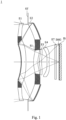
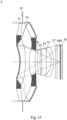
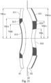
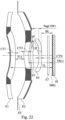
- Fig. 1 is a schematic view of an imaging apparatus 1 according to the 1st embodiment of the present disclosure.
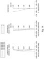
- Fig. 2 shows, in order from left to right, spherical aberration curves, astigmatic field curves and a distortion curve of the imaging apparatus 1 according to the 1st embodiment.
- the imaging apparatus 1 according to the 1st embodiment includes an imaging system lens assembly (reference number is omitted) and an image sensor IS.
- the imaging system lens assembly includes, in order from an object side to an image side, a first lens element E1, an aperture stop ST, a stop S1, a second lens element E2, a third lens element E3, a fourth lens element E4, a filter E7 and an image surface IMG, wherein the image sensor IS is disposed on the image surface IMG of the imaging system lens assembly.
- the imaging system lens assembly includes four lens elements (E1, E2, E3, E4) without additional one or more lens elements inserted between the first lens element E1 and the fourth lens element E4.
- the first lens element E1 and the second lens element E2 belong to a first lens group
- the third lens element E3, the fourth lens element E4 belong to a second lens group.
- Fig. 21 is a schematic view of the first lens element E1 and the second lens element E2 according to the 1st embodiment of Fig. 1 .
- the first lens element E1 is a first catadioptric lens element, and has an object-side surface facing towards the object side and an image-side surface facing towards the image side.
- the object-side surface of the first catadioptric lens element includes a central region and a peripheral region
- the image-side surface of the first catadioptric lens element includes a central region and a peripheral region.
- the peripheral region of the object-side surface of the first catadioptric lens element includes a first refracting surface E11.
- the central region of the object-side surface of the first catadioptric lens element includes a second reflecting surface E12.
- Each of the object-side surface and the image-side surface of the first catadioptric lens element includes a light blocking area E13 between the central region and the peripheral region thereof.
- the first lens element E1 is made of a plastic material, and has the peripheral region of the object-side surface (i.e. the first refracting surface E11) being convex, the central region of the object-side surface (i.e. the second reflecting surface E12) being concave, the peripheral region of the image-side surface being concave, the central region of the image-side surface being convex, and all being aspheric.
- the second lens element E2 is a second catadioptric lens element, and has an object-side surface facing towards the object side and an image-side surface facing towards the image side.
- the object-side surface of the second catadioptric lens element includes a central region and a peripheral region
- the image-side surface of the second catadioptric lens element includes a central region and a peripheral region.
- the peripheral region of the image-side surface of the second catadioptric lens element includes a first reflecting surface E21.
- the central region of the image-side surface of the second catadioptric lens element includes a last refracting surface E22.
- Each of the object-side surface and the image-side surface of the second catadioptric lens element includes a light blocking area E23 between the central region and the peripheral region thereof.
- the second lens element E2 is made of a plastic material, and has the peripheral region of the object-side surface being concave, the central region of the object-side surface being convex, the peripheral region of the image-side surface (i.e. the first reflecting surface E21) being convex, the central region of the image-side surface (i.e. the last refracting surface E22) being concave, and all being aspheric.
- the third lens element E3 with positive refractive power has the object-side surface being convex in a paraxial region thereof and the image-side surface being concave in a paraxial region thereof.
- the third lens element E3 is made of a plastic material, and has the object-side surface and the image-side surface being both aspheric.
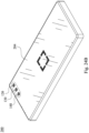
- Fig. 22 is a schematic view of partial parameters and the inflection points IP of the third lens element E3 according to the 1st embodiment of Fig. 1 . As shown in Fig. 22 , the object-side surface of the third lens element E3 includes two inflection points IP (as shown in Fig. 22 ), and the image-side surface of the third lens element E3 includes three inflection points IP (as shown in Fig. 22 ).
- the fourth lens element E4 with negative refractive power has the object-side surface being convex in a paraxial region thereof and the image-side surface being concave in a paraxial region thereof.
- the fourth lens element E4 is made of a plastic material, and has the object-side surface and the image-side surface being both aspheric. Further, the object-side surface of the fourth lens element E4 includes two inflection points IP (as shown in Fig. 22 ), and the image-side surface of the fourth lens element E4 includes one inflection point IP (as shown in Fig. 22 ).
- the filter E7 is made of a glass material, which is located between the fourth lens element E4 and the image surface IMG in order, and will not affect the focal length of the imaging system lens assembly.
- f 13.04 mm
- Fno 1.68
- HFOV 10.9 degrees
- a maximum image height of the imaging system lens assembly is ImgH
- the focal length of the imaging system lens assembly is f
- an axial distance between the image-side surface of the lens element of the second lens group closest to the image surface IMG is BL
- a maximum effective radius of the peripheral region of the object-side surface of the first catadioptric lens element i.e. the first lens element E1
- a minimum effective radius of the peripheral region of the object-side surface of the first catadioptric lens element i.e. the first lens element E1
- a maximum effective radius of the peripheral region of the image-side surface of the second catadioptric lens element i.e. the second lens element E2
- a minimum effective radius of the peripheral region of the image-side surface of the second catadioptric lens element i.e.
- the second lens element E2) is YM1i
- a maximum effective radius of the central region of the object-side surface of the first catadioptric lens element (i.e. the first lens element E1) is YM2
- a maximum effective radius of the central region of the image-side surface of the second catadioptric lens element (i.e. the second lens element E2) is YRL
- an axial distance between the image-side surface of the first catadioptric lens element (i.e. the first lens element E1) and the object-side surface of the second catadioptric lens element i.e.
- Table 1A The detailed optical data of the 1st embodiment are shown in Table 1A and the aspheric surface data are shown in Table 1B below.
- Effective radius of Surface 10 (stop S1) is 1.626 mm.
- Table 1A shows the detailed optical data of Fig. 1 of the 1st embodiment, wherein the curvature radius, thickness and the focal length are shown in millimeters (mm), Surface numbers 0-19 represent the surfaces sequentially arranged from the object side to the image side, the Index is the refractive index measured at the Reference wavelength.
- Table 1B shows the aspheric surface data of the 1st embodiment, wherein k represents the conic coefficient of the equation of the aspheric surface profiles, and A4-A20 represent the aspheric coefficients of each surface ranging from the 4th order to the 20th order.
- the tables presented below for each embodiment correspond to the schematic view and aberration curves of each embodiment, and term definitions of the tables are the same as those in Table 1A and Table 1B of the 1st embodiment. Therefore, an explanation in this regard will not be provided again.
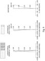
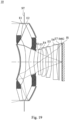
- Fig. 3 is a schematic view of an imaging apparatus 2 according to the 2nd embodiment of the present disclosure.
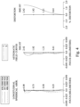
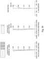
- Fig. 4 shows, in order from left to right, spherical aberration curves, astigmatic field curves and a distortion curve of the imaging apparatus 2 according to the 2nd embodiment.
- the imaging apparatus 2 according to the 2nd embodiment includes an imaging system lens assembly (reference number is omitted) and an image sensor IS.
- the imaging system lens assembly includes, in order from an object side to an image side, a first lens element E1, an aperture stop ST, a stop S1, a second lens element E2, a third lens element E3, a fourth lens element E4, a filter E7 and an image surface IMG, wherein the image sensor IS is disposed on the image surface IMG of the imaging system lens assembly.
- the imaging system lens assembly includes four lens elements (E1, E2, E3, E4) without additional one or more lens elements inserted between the first lens element E1 and the fourth lens element E4.
- the first lens element E1 and the second lens element E2 belong to a first lens group
- the third lens element E3, the fourth lens element E4 belong to a second lens group.
- the first lens element E1 is a first catadioptric lens element, and can be the same as or similar to the first lens element E1 of the 1st embodiment in Fig. 21 and will not be described again herein.
- the first lens element E1 is made of a plastic material, and has the peripheral region of the object-side surface (i.e. the first refracting surface) being convex, the central region of the object-side surface (i.e. the second reflecting surface) being concave, the peripheral region of the image-side surface being concave, the central region of the image-side surface being convex, and all being aspheric.
- the second lens element E2 is a second catadioptric lens element, and can be the same as or similar to the second lens element E2 of the 1st embodiment in Fig. 21 and will not be described again herein.
- the second lens element E2 is made of a plastic material, and has the peripheral region of the object-side surface being concave, the central region of the object-side surface being convex, the peripheral region of the image-side surface (i.e. the first reflecting surface) being convex, the central region of the image-side surface (i.e. the last refracting surface) being convex, and all being aspheric.
- the third lens element E3 with negative refractive power has the object-side surface being convex in a paraxial region thereof and the image-side surface being concave in a paraxial region thereof.
- the third lens element E3 is made of a plastic material, and has the object-side surface and the image-side surface being both aspheric. Further, the object-side surface of the third lens element E3 includes one inflection point, and the image-side surface of the third lens element E3 includes one inflection point.
- the fourth lens element E4 with negative refractive power has the object-side surface being concave in a paraxial region thereof and the image-side surface being convex in a paraxial region thereof.
- the fourth lens element E4 is made of a plastic material, and has the object-side surface and the image-side surface being both aspheric.
- the filter E7 is made of a glass material, which is located between the fourth lens element E4 and the image surface IMG in order, and will not affect the focal length of the imaging system lens assembly.
- Table 2A The detailed optical data of the 2nd embodiment are shown in Table 2A and the aspheric surface data are shown in Table 2B below.
- Effective radius of Surface 10 (stop S1) is 1.626 mm.
- the equation of the aspheric surface profiles of the aforementioned lens elements is the same as the equation of the 1st embodiment. Also, the definitions of these parameters shown in the following table are the same as those stated in the 1st embodiment with corresponding values for the 2nd embodiment, so an explanation in this regard will not be provided again.
- Table 2C can be calculated from Table 2A and Table 2B as the following values and satisfy the following conditions: Table 2C - 2nd Embodiment f [mm] 12.95 YM1i [mm] 3.23 Fno 1.94 YM2 [mm] 2.51 HFOV [deg.] 10.4 YRL [mm] 1.66 TL/ImgH 2.33 YR1o/ImgH 2.08 TL/f 0.43 (YR1i-YRL)/T12 2.35 ImgH/f 0.19 YM2/YRL 1.51 BL/ImgH 0.80 (YR1o-YR1i)/(YM1o-YM1i) 0.75 (R8-R9)/(R8+R9) 2.51 YR1o/YR1i 1.38 (RM2+R11)/(RM2-R11) -0.50 YM1o/YM1i 1.57 RM2/R9 -0.86 SagLNR1/CTN -1
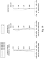
- Fig. 5 is a schematic view of an imaging apparatus 3 according to the 3rd embodiment of the present disclosure.
- Fig. 6 shows, in order from left to right, spherical aberration curves, astigmatic field curves and a distortion curve of the imaging apparatus 3 according to the 3rd embodiment.
- the imaging apparatus 3 according to the 3rd embodiment includes an imaging system lens assembly (reference number is omitted) and an image sensor IS.
- the imaging system lens assembly includes, in order from an object side to an image side, a first lens element E1, an aperture stop ST, a second lens element E2, a third lens element E3, a fourth lens element E4, a fifth lens element E5, a filter E7 and an image surface IMG, wherein the image sensor IS is disposed on the image surface IMG of the imaging system lens assembly.
- the imaging system lens assembly includes five lens elements (E1, E2, E3, E4, E5) without additional one or more lens elements inserted between the first lens element E1 and the fifth lens element E5.
- the first lens element E1 and the second lens element E2 belong to a first lens group
- the third lens element E3, the fourth lens element E4 and the fifth lens element E5 belong to a second lens group.
- the first lens element E1 is a first catadioptric lens element, and can be the same as or similar to the first lens element E1 of the 1st embodiment in Fig. 21 and will not be described again herein.
- the first lens element E1 is made of a plastic material, and has the peripheral region of the object-side surface (i.e. the first refracting surface) being convex, the central region of the object-side surface (i.e. the second reflecting surface) being concave, the peripheral region of the image-side surface being concave, the central region of the image-side surface being convex, and all being aspheric.
- the second lens element E2 is a second catadioptric lens element, and can be the same as or similar to the second lens element E2 of the 1st embodiment in Fig. 21 and will not be described again herein.
- the second lens element E2 is made of a plastic material, and has the peripheral region of the object-side surface being concave, the central region of the object-side surface being convex, the peripheral region of the image-side surface (i.e. the first reflecting surface) being convex, the central region of the image-side surface (i.e. the last refracting surface) being concave, and all being aspheric.
- the third lens element E3 with positive refractive power has the object-side surface being convex in a paraxial region thereof and the image-side surface being concave in a paraxial region thereof.
- the third lens element E3 is made of a plastic material, and has the object-side surface and the image-side surface being both aspheric. Further, the object-side surface of the third lens element E3 includes one inflection point, and the image-side surface of the third lens element E3 includes one inflection point.
- the fourth lens element E4 with positive refractive power has the object-side surface being convex in a paraxial region thereof and the image-side surface being convex in a paraxial region thereof.
- the fourth lens element E4 is made of a plastic material, and has the object-side surface and the image-side surface being both aspheric. Further, the object-side surface of the fourth lens element E4 includes two inflection points, and the image-side surface of the fourth lens element E4 includes three inflection points.
- the fifth lens element E5 with negative refractive power has the object-side surface being concave in a paraxial region thereof and the image-side surface being concave in a paraxial region thereof.
- the fifth lens element E5 is made of a plastic material, and has the object-side surface and the image-side surface being both aspheric. Further, the object-side surface of the fifth lens element E5 includes one inflection point, and the image-side surface of the fifth lens element E5 includes one inflection point.
- the filter E7 is made of a glass material, which is located between the fifth lens element E5 and the image surface IMG in order, and will not affect the focal length of the imaging system lens assembly.
- Table 3A The detailed optical data of the 3rd embodiment are shown in Table 3A and the aspheric surface data are shown in Table 3B below.
- the equation of the aspheric surface profiles of the aforementioned lens elements is the same as the equation of the 1st embodiment. Also, the definitions of these parameters shown in the following table are the same as those stated in the 1st embodiment with corresponding values for the 3rd embodiment, so an explanation in this regard will not be provided again.
- Table 3C can be calculated from Table 3A and Table 3B as the following values and satisfy the following conditions: Table 3C - 3rd Embodiment f [mm] 14.00 YM1i [mm] 2.93 Fno 1.80 YM2 [mm] 2.49 HFOV [deg.] 9.6 YRL [mm] 2.16 TL/ImgH 2.36 YR1o/ImgH 2.15 TL/f 0.40 (YR1i-YRL)/T12 0.84 ImgH/f 0.17 YM2/YRL 1.15 BL/ImgH 0.38 (YR1o-YR1i)/(YM1o-YM1i) 0.85 (R8-R9)/(R8+R9) 1.38 YR1o/YR1i 1.59 (RM2+R11)/(RM2-R11) 0.17 YM1o/YM1i 1.76 RM2/R9 -1.54 SagLNR1/CTN -1.
- Fig. 7 is a schematic view of an imaging apparatus 4 according to the 4th embodiment of the present disclosure.
- Fig. 8 shows, in order from left to right, spherical aberration curves, astigmatic field curves and a distortion curve of the imaging apparatus 4 according to the 4th embodiment.
- the imaging apparatus 4 according to the 4th embodiment includes an imaging system lens assembly (reference number is omitted) and an image sensor IS.
- the imaging system lens assembly includes, in order from an object side to an image side, a first lens element E1, an aperture stop ST, a stop S1, a second lens element E2, a third lens element E3, a fourth lens element E4, a fifth lens element E5, a filter E7 and an image surface IMG, wherein the image sensor IS is disposed on the image surface IMG of the imaging system lens assembly.
- the imaging system lens assembly includes five lens elements (E1, E2, E3, E4, E5) without additional one or more lens elements inserted between the first lens element E1 and the fifth lens element E5.
- the first lens element E1 and the second lens element E2 belong to a first lens group
- the third lens element E3, the fourth lens element E4 and the fifth lens element E5 belong to a second lens group.
- the first lens element E1 is a first catadioptric lens element, and can be the same as or similar to the first lens element E1 of the 1st embodiment in Fig. 21 and will not be described again herein.
- the first lens element E1 is made of a plastic material, and has the peripheral region of the object-side surface (i.e. the first refracting surface) being convex, the central region of the object-side surface (i.e. the second reflecting surface) being concave, the peripheral region of the image-side surface being concave, the central region of the image-side surface being convex, and all being aspheric.
- the second lens element E2 is a second catadioptric lens element, and can be the same as or similar to the second lens element E2 of the 1st embodiment in Fig. 21 and will not be described again herein.
- the second lens element E2 is made of a plastic material, and has the peripheral region of the object-side surface being concave, the central region of the object-side surface being convex, the peripheral region of the image-side surface (i.e. the first reflecting surface) being convex, the central region of the image-side surface (i.e. the last refracting surface) being concave, and all being aspheric.
- the third lens element E3 with negative refractive power has the object-side surface being convex in a paraxial region thereof and the image-side surface being concave in a paraxial region thereof.
- the third lens element E3 is made of a plastic material, and has the object-side surface and the image-side surface being both aspheric. Further, the object-side surface of the third lens element E3 includes one inflection point, and the image-side surface of the third lens element E3 includes one inflection point.
- the fourth lens element E4 with negative refractive power has the object-side surface being convex in a paraxial region thereof and the image-side surface being concave in a paraxial region thereof.
- the fourth lens element E4 is made of a plastic material, and has the object-side surface and the image-side surface being both aspheric. Further, the object-side surface of the fourth lens element E4 includes two inflection points, and the image-side surface of the fourth lens element E4 includes two inflection points.
- the fifth lens element E5 with negative refractive power has the object-side surface being convex in a paraxial region thereof and the image-side surface being concave in a paraxial region thereof.
- the fifth lens element E5 is made of a plastic material, and has the object-side surface and the image-side surface being both aspheric. Further, the object-side surface of the fifth lens element E5 includes two inflection points, and the image-side surface of the fifth lens element E5 includes one inflection point.
- the filter E7 is made of a glass material, which is located between the fifth lens element E5 and the image surface IMG in order, and will not affect the focal length of the imaging system lens assembly.
- Table 4A The detailed optical data of the 4th embodiment are shown in Table 4A and the aspheric surface data are shown in Table 4B below.
- Effective radius of Surface 10 (stop S1) is 1.646 mm.
- the equation of the aspheric surface profiles of the aforementioned lens elements is the same as the equation of the 1st embodiment. Also, the definitions of these parameters shown in the following table are the same as those stated in the 1st embodiment with corresponding values for the 4th embodiment, so an explanation in this regard will not be provided again.
- Table 4C can be calculated from Table 4A and Table 4B as the following values and satisfy the following conditions: Table 4C - 4th Embodiment f [mm] 15.66 YM1i [mm] 3.25 Fno 1.76 YM2 [mm] 2.52 HFOV [deg.] 9.0 YRL [mm] 1.67 TL/ImgH 2.36 YR1o/ImgH 2.40 TL/f 0.38 (YR1i-YRL)/T12 2.28 ImgH/f 0.16 YM2/YRL 1.51 BL/ImgH 0.42 (YR1o-YR1i)/(YM1o-YM1i) 0.75 (R8-R9)/(R8+R9) 1.20 YR1o/YR1i 1.54 (RM2+R11)/(RM2-R11) 0.00 YM1o/YM1i 1.86 RM2/R9 -1.60 SagLNR1/CTN -1.48
- Fig. 9 is a schematic view of an imaging apparatus 5 according to the 5th embodiment of the present disclosure.
- Fig. 10 shows, in order from left to right, spherical aberration curves, astigmatic field curves and a distortion curve of the imaging apparatus 5 according to the 5th embodiment.
- the imaging apparatus 5 according to the 5th embodiment includes an imaging system lens assembly (reference number is omitted) and an image sensor IS.
- the imaging system lens assembly includes, in order from an object side to an image side, a first lens element E1, an aperture stop ST, a stop S1, a second lens element E2, a third lens element E3, a fourth lens element E4, a fifth lens element E5, a filter E7 and an image surface IMG, wherein the image sensor IS is disposed on the image surface IMG of the imaging system lens assembly.
- the imaging system lens assembly includes five lens elements (E1, E2, E3, E4, E5) without additional one or more lens elements inserted between the first lens element E1 and the fifth lens element E5.
- the first lens element E1 and the second lens element E2 belong to a first lens group
- the third lens element E3, the fourth lens element E4 and the fifth lens element E5 belong to a second lens group.
- the first lens element E1 is a first catadioptric lens element, and can be the same as or similar to the first lens element E1 of the 1st embodiment in Fig. 21 and will not be described again herein.
- the first lens element E1 is made of a plastic material, and has the peripheral region of the object-side surface (i.e. the first refracting surface) being convex, the central region of the object-side surface (i.e. the second reflecting surface) being concave, the peripheral region of the image-side surface being concave, the central region of the image-side surface being convex, and all being aspheric.
- the second lens element E2 is a second catadioptric lens element, and can be the same as or similar to the second lens element E2 of the 1st embodiment in Fig. 21 and will not be described again herein.
- the second lens element E2 is made of a plastic material, and has the peripheral region of the object-side surface being concave, the central region of the object-side surface being convex, the peripheral region of the image-side surface (i.e. the first reflecting surface) being convex, the central region of the image-side surface (i.e. the last refracting surface) being concave, and all being aspheric.
- the third lens element E3 with negative refractive power has the object-side surface being convex in a paraxial region thereof and the image-side surface being concave in a paraxial region thereof.
- the third lens element E3 is made of a plastic material, and has the object-side surface and the image-side surface being both aspheric. Further, the object-side surface of the third lens element E3 includes one inflection point, and the image-side surface of the third lens element E3 includes one inflection point.
- the fourth lens element E4 with positive refractive power has the object-side surface being convex in a paraxial region thereof and the image-side surface being concave in a paraxial region thereof.
- the fourth lens element E4 is made of a plastic material, and has the object-side surface and the image-side surface being both aspheric. Further, the object-side surface of the fourth lens element E4 includes one inflection point, and the image-side surface of the fourth lens element E4 includes one inflection point.
- the fifth lens element E5 with negative refractive power has the object-side surface being concave in a paraxial region thereof and the image-side surface being convex in a paraxial region thereof.
- the fifth lens element E5 is made of a plastic material, and has the object-side surface and the image-side surface being both aspheric. Further, the object-side surface of the fifth lens element E5 includes one inflection point.
- the filter E7 is made of a glass material, which is located between the fifth lens element E5 and the image surface IMG in order, and will not affect the focal length of the imaging system lens assembly.
- Table 5A The detailed optical data of the 5th embodiment are shown in Table 5A and the aspheric surface data are shown in Table 5B below.
- Effective radius of Surface 10 (stop S1) is 1.646 mm.
- the equation of the aspheric surface profiles of the aforementioned lens elements is the same as the equation of the 1st embodiment. Also, the definitions of these parameters shown in the following table are the same as those stated in the 1st embodiment with corresponding values for the 5th embodiment, so an explanation in this regard will not be provided again.
- Table 5C can be calculated from Table 5A and Table 5B as the following values and satisfy the following conditions: Table 5C - 5th Embodiment f [mm] 14.34 YM1i [mm] 3.40 Fno 1.81 YM2 [mm] 2.44 HFOV [deg.] 9.6 YRL [mm] 1.66 TL/ImgH 2.37 YR1o/ImgH 2.30 TL/f 0.40 (YR1i-YRL)/T12 2.61 ImgH/f 0.17 YM2/YRL 1.47 BL/ImgH 0.37 (YR1o-YR1i)/(YM1o-YM1i) 0.85 (R8-R9)/(R8+R9) 1.28 YR1o/YR1i 1.48 (RM2+R11)/(RM2-R11) -0.03 YM1o/YM1i 1.63 RM2/R9 -1.29 SagLNR1/CTN -2
- Fig. 11 is a schematic view of an imaging apparatus 6 according to the 6th embodiment of the present disclosure.
- Fig. 12 shows, in order from left to right, spherical aberration curves, astigmatic field curves and a distortion curve of the imaging apparatus 6 according to the 6th embodiment.
- the imaging apparatus 6 according to the 6th embodiment includes an imaging system lens assembly (reference number is omitted) and an image sensor IS.
- the imaging system lens assembly includes, in order from an object side to an image side, a first lens element E1, an aperture stop ST, a second lens element E2, a stop S1, a third lens element E3, a fourth lens element E4, a fifth lens element E5, a filter E7 and an image surface IMG, wherein the image sensor IS is disposed on the image surface IMG of the imaging system lens assembly.
- the imaging system lens assembly includes five lens elements (E1, E2, E3, E4, E5) without additional one or more lens elements inserted between the first lens element E1 and the fifth lens element E5.
- the first lens element E1 and the second lens element E2 belong to a first lens group
- the third lens element E3, the fourth lens element E4 and the fifth lens element E5 belong to a second lens group.
- the first lens element E1 is a first catadioptric lens element, and can be the same as or similar to the first lens element E1 of the 1st embodiment in Fig. 21 and will not be described again herein.
- the first lens element E1 is made of a plastic material, and has the peripheral region of the object-side surface (i.e. the first refracting surface) being convex, the central region of the object-side surface (i.e. the second reflecting surface) being concave, the peripheral region of the image-side surface being concave, the central region of the image-side surface being convex, and all being aspheric.
- the second lens element E2 is a second catadioptric lens element, and can be the same as or similar to the second lens element E2 of the 1st embodiment in Fig. 21 and will not be described again herein.
- the second lens element E2 is made of a plastic material, and has the peripheral region of the object-side surface being concave, the central region of the object-side surface being convex, the peripheral region of the image-side surface (i.e. the first reflecting surface) being convex, the central region of the image-side surface (i.e. the last refracting surface) being concave, and all being aspheric.
- the third lens element E3 with positive refractive power has the object-side surface being convex in a paraxial region thereof and the image-side surface being convex in a paraxial region thereof.
- the third lens element E3 is made of a plastic material, and has the object-side surface and the image-side surface being both aspheric. Further, the object-side surface of the third lens element E3 includes one inflection point, and the image-side surface of the third lens element E3 includes two inflection points.
- the fourth lens element E4 with negative refractive power has the object-side surface being convex in a paraxial region thereof and the image-side surface being concave in a paraxial region thereof.
- the fourth lens element E4 is made of a plastic material, and has the object-side surface and the image-side surface being both aspheric. Further, the object-side surface of the fourth lens element E4 includes one inflection point, and the image-side surface of the fourth lens element E4 includes one inflection point.
- the fifth lens element E5 with negative refractive power has the object-side surface being concave in a paraxial region thereof and the image-side surface being concave in a paraxial region thereof.
- the fifth lens element E5 is made of a plastic material, and has the object-side surface and the image-side surface being both aspheric. Further, the object-side surface of the fifth lens element E5 includes one inflection point, and the image-side surface of the fifth lens element E5 includes two inflection points.
- the filter E7 is made of a glass material, which is located between the fifth lens element E5 and the image surface IMG in order, and will not affect the focal length of the imaging system lens assembly.
- Table 6A The detailed optical data of the 6th embodiment are shown in Table 6A and the aspheric surface data are shown in Table 6B below.
- Effective radius of Surface 12 (stop S1) is 1.605 mm.
- the equation of the aspheric surface profiles of the aforementioned lens elements is the same as the equation of the 1st embodiment. Also, the definitions of these parameters shown in the following table are the same as those stated in the 1st embodiment with corresponding values for the 6th embodiment, so an explanation in this regard will not be provided again.
- Table 6C can be calculated from Table 6A and Table 6B as the following values and satisfy the following conditions: Table 6C - 6th Embodiment f [mm] 14.34 YM1i [mm] 3.40 Fno 1.82 YM2 [mm] 2.47 HFOV [deg.] 9.6 YRL [mm] 1.63 TL/ImgH 2.34 YR1o/ImgH 2.29 TL/f 0.39 (YR1i-YRL)/T12 4.07 ImgH/f 0.17 YM2/YRL 1.52 BL/ImgH 0.39 (YR1o-YR1i)/(YM1o-YM1i) 0.82 (R8-R9)/(R8+R9) 1.25 YR1o/YR1i 1.48 (RM2+R11)/(RM2-R11) -0.12 YM1o/YM1i 1.63 RM2/R9 -1.54 SagLNR1/CTN -1
- Fig. 13 is a schematic view of an imaging apparatus 7 according to the 7th embodiment of the present disclosure.
- Fig. 14 shows, in order from left to right, spherical aberration curves, astigmatic field curves and a distortion curve of the imaging apparatus 7 according to the 7th embodiment.
- the imaging apparatus 7 according to the 7th embodiment includes an imaging system lens assembly (reference number is omitted) and an image sensor IS.
- the imaging system lens assembly includes, in order from an object side to an image side, a first lens element E1, an aperture stop ST, a second lens element E2, a stop S1, a third lens element E3, a fourth lens element E4, a fifth lens element E5, a filter E7 and an image surface IMG, wherein the image sensor IS is disposed on the image surface IMG of the imaging system lens assembly.
- the imaging system lens assembly includes five lens elements (E1, E2, E3, E4, E5) without additional one or more lens elements inserted between the first lens element E1 and the fifth lens element E5.
- the first lens element E1 and the second lens element E2 belong to a first lens group
- the third lens element E3, the fourth lens element E4 and the fifth lens element E5 belong to a second lens group.
- the first lens element E1 is a first catadioptric lens element, and can be the same as or similar to the first lens element E1 of the 1st embodiment in Fig. 21 and will not be described again herein.
- the first lens element E1 is made of a plastic material, and has the peripheral region of the object-side surface (i.e. the first refracting surface) being convex, the central region of the object-side surface (i.e. the second reflecting surface) being concave, the peripheral region of the image-side surface being concave, the central region of the image-side surface being convex, and all being aspheric.
- the second lens element E2 is a second catadioptric lens element, and can be the same as or similar to the second lens element E2 of the 1st embodiment in Fig. 21 and will not be described again herein.
- the second lens element E2 is made of a plastic material, and has the peripheral region of the object-side surface being concave, the central region of the object-side surface being convex, the peripheral region of the image-side surface (i.e. the first reflecting surface) being convex, the central region of the image-side surface (i.e. the last refracting surface) being concave, and all being aspheric.
- the third lens element E3 with positive refractive power has the object-side surface being convex in a paraxial region thereof and the image-side surface being convex in a paraxial region thereof.
- the third lens element E3 is made of a plastic material, and has the object-side surface and the image-side surface being both aspheric. Further, the object-side surface of the third lens element E3 includes one inflection point, and the image-side surface of the third lens element E3 includes two inflection points.
- the fourth lens element E4 with negative refractive power has the object-side surface being convex in a paraxial region thereof and the image-side surface being concave in a paraxial region thereof.
- the fourth lens element E4 is made of a plastic material, and has the object-side surface and the image-side surface being both aspheric. Further, the object-side surface of the fourth lens element E4 includes one inflection point, and the image-side surface of the fourth lens element E4 includes one inflection point.
- the fifth lens element E5 with negative refractive power has the object-side surface being convex in a paraxial region thereof and the image-side surface being concave in a paraxial region thereof.
- the fifth lens element E5 is made of a plastic material, and has the object-side surface and the image-side surface being both aspheric. Further, the object-side surface of the fifth lens element E5 includes two inflection points, and the image-side surface of the fifth lens element E5 includes two inflection points.
- the filter E7 is made of a glass material, which is located between the fifth lens element E5 and the image surface IMG in order, and will not affect the focal length of the imaging system lens assembly.
- Table 7A The detailed optical data of the 7th embodiment are shown in Table 7A and the aspheric surface data are shown in Table 7B below.
- Effective radius of Surface 12 (stop S1) is 1.608 mm.
- the equation of the aspheric surface profiles of the aforementioned lens elements is the same as the equation of the 1st embodiment. Also, the definitions of these parameters shown in the following table are the same as those stated in the 1st embodiment with corresponding values for the 7th embodiment, so an explanation in this regard will not be provided again.
- Table 7C can be calculated from Table 7A and Table 7B as the following values and satisfy the following conditions: Table 7C - 7th Embodiment f [mm] 13.33 YM1i [mm] 3.40 Fno 1.81 YM2 [mm] 2.50 HFOV [deg.] 10.2 YRL [mm] 1.63 TL/ImgH 2.37 YR1o/ImgH 2.20 TL/f 0.43 (YR1i-YRL)/T12 4.80 ImgH/f 0.18 YM2/YRL 1.53 BL/ImgH 0.54 (YR1o-YR1i)/(YM1o-YM1i) 0.81 (R8-R9)/(R8+R9) 1.33 YR1o/YR1i 1.43 (RM2+R11)/(RM2-R11) -0.18 YM1o/YM1i 1.58 RM2/R9 -1.61 SagLNR1/CTN -
- Fig. 15 is a schematic view of an imaging apparatus 8 according to the 8th embodiment of the present disclosure.
- Fig. 16 shows, in order from left to right, spherical aberration curves, astigmatic field curves and a distortion curve of the imaging apparatus 8 according to the 8th embodiment.
- the imaging apparatus 8 according to the 8th embodiment includes an imaging system lens assembly (reference number is omitted) and an image sensor IS.
- the imaging system lens assembly includes, in order from an object side to an image side, a first lens element E1, an aperture stop ST, a second lens element E2, a stop S1, a third lens element E3, a fourth lens element E4, a fifth lens element E5, a filter E7 and an image surface IMG, wherein the image sensor IS is disposed on the image surface IMG of the imaging system lens assembly.
- the imaging system lens assembly includes five lens elements (E1, E2, E3, E4, E5) without additional one or more lens elements inserted between the first lens element E1 and the fifth lens element E5.
- the first lens element E1 and the second lens element E2 belong to a first lens group
- the third lens element E3, the fourth lens element E4 and the fifth lens element E5 belong to a second lens group.
- the first lens element E1 is a first catadioptric lens element, and can be the same as or similar to the first lens element E1 of the 1st embodiment in Fig. 21 and will not be described again herein.
- the first lens element E1 is made of a plastic material, and has the peripheral region of the object-side surface (i.e. the first refracting surface) being convex, the central region of the object-side surface (i.e. the second reflecting surface) being concave, the peripheral region of the image-side surface being concave, the central region of the image-side surface being convex, and all being aspheric.
- the second lens element E2 is a second catadioptric lens element, and can be the same as or similar to the second lens element E2 of the 1st embodiment in Fig. 21 and will not be described again herein.
- the second lens element E2 is made of a plastic material, and has the peripheral region of the object-side surface being concave, the central region of the object-side surface being convex, the peripheral region of the image-side surface (i.e. the first reflecting surface) being convex, the central region of the image-side surface (i.e. the last refracting surface) being concave, and all being aspheric.
- the third lens element E3 with positive refractive power has the object-side surface being convex in a paraxial region thereof and the image-side surface being concave in a paraxial region thereof.
- the third lens element E3 is made of a plastic material, and has the object-side surface and the image-side surface being both aspheric. Further, the object-side surface of the third lens element E3 includes one inflection point, and the image-side surface of the third lens element E3 includes one inflection point.
- the fourth lens element E4 with positive refractive power has the object-side surface being convex in a paraxial region thereof and the image-side surface being concave in a paraxial region thereof.
- the fourth lens element E4 is made of a plastic material, and has the object-side surface and the image-side surface being both aspheric. Further, the object-side surface of the fourth lens element E4 includes one inflection point, and the image-side surface of the fourth lens element E4 includes one inflection point.
- the fifth lens element E5 with negative refractive power has the object-side surface being concave in a paraxial region thereof and the image-side surface being concave in a paraxial region thereof.
- the fifth lens element E5 is made of a plastic material, and has the object-side surface and the image-side surface being both aspheric. Further, the image-side surface of the fifth lens element E5 includes one inflection point.
- the filter E7 is made of a glass material, which is located between the fifth lens element E5 and the image surface IMG in order, and will not affect the focal length of the imaging system lens assembly.
- Table 8A The detailed optical data of the 8th embodiment are shown in Table 8A and the aspheric surface data are shown in Table 8B below.
- Effective radius of Surface 12 (stop S1) is 1.605 mm.
- the equation of the aspheric surface profiles of the aforementioned lens elements is the same as the equation of the 1st embodiment. Also, the definitions of these parameters shown in the following table are the same as those stated in the 1st embodiment with corresponding values for the 8th embodiment, so an explanation in this regard will not be provided again.
- Table 8C can be calculated from Table 8A and Table 8B as the following values and satisfy the following conditions: Table 8C - 8th Embodiment f [mm] 14.39 YM1i [mm] 3.40 Fno 1.83 YM2 [mm] 2.40 HFOV [deg.] 9.6 YRL [mm] 1.62 TL/ImgH 2.35 YR1o/ImgH 2.28 TL/f 0.39 (YR1i-YRL)/T12 4.08 ImgH/f 0.17 YM2/YRL 1.48 BL/ImgH 0.41 (YR1o-YR1i)/(YM1o-YM1i) 0.81 (R8-R9)/(R8+R9) 1.21 YR1o/YR1i 1.46 (RM2+R11)/(RM2-R11) -0.02 YM1o/YM1i 1.63 RM2/R9 -1.46 SagLNR1/CTN -2
- Fig. 17 is a schematic view of an imaging apparatus 9 according to the 9th embodiment of the present disclosure.
- Fig. 18 shows, in order from left to right, spherical aberration curves, astigmatic field curves and a distortion curve of the imaging apparatus 9 according to the 9th embodiment.
- the imaging apparatus 9 according to the 9th embodiment includes an imaging system lens assembly (reference number is omitted) and an image sensor IS.
- the imaging system lens assembly includes, in order from an object side to an image side, a first lens element E1, an aperture stop ST, a stop S1, a second lens element E2, a third lens element E3, a fourth lens element E4, a fifth lens element E5, a sixth lens element E6, a filter E7 and an image surface IMG, wherein the image sensor IS is disposed on the image surface IMG of the imaging system lens assembly.
- the imaging system lens assembly includes six lens elements (E1, E2, E3, E4, E5, E6) without additional one or more lens elements inserted between the first lens element E1 and the sixth lens element E6.
- the first lens element E1 and the second lens element E2 belong to a first lens group
- the third lens element E3, the fourth lens element E4, the fifth lens element E5 and the sixth lens element E6 belong to a second lens group.
- the first lens element E1 is a first catadioptric lens element, and can be the same as or similar to the first lens element E1 of the 1st embodiment in Fig. 21 and will not be described again herein.
- the first lens element E1 is made of a plastic material, and has the peripheral region of the object-side surface (i.e. the first refracting surface) being convex, the central region of the object-side surface (i.e. the second reflecting surface) being concave, the peripheral region of the image-side surface being concave, the central region of the image-side surface being convex, and all being aspheric.
- the second lens element E2 is a second catadioptric lens element, and can be the same as or similar to the second lens element E2 of the 1st embodiment in Fig. 21 and will not be described again herein.
- the second lens element E2 is made of a plastic material, and has the peripheral region of the object-side surface being concave, the central region of the object-side surface being convex, the peripheral region of the image-side surface (i.e. the first reflecting surface) being convex, the central region of the image-side surface (i.e. the last refracting surface) being concave, and all being aspheric.
- the third lens element E3 with negative refractive power has the object-side surface being convex in a paraxial region thereof and the image-side surface being concave in a paraxial region thereof.
- the third lens element E3 is made of a plastic material, and has the object-side surface and the image-side surface being both aspheric. Further, the object-side surface of the third lens element E3 includes one inflection point, and the image-side surface of the third lens element E3 includes three inflection points.
- the fourth lens element E4 with positive refractive power has the object-side surface being convex in a paraxial region thereof and the image-side surface being concave in a paraxial region thereof.
- the fourth lens element E4 is made of a plastic material, and has the object-side surface and the image-side surface being both aspheric. Further, the object-side surface of the fourth lens element E4 includes two inflection points, and the image-side surface of the fourth lens element E4 includes two inflection points.
- the fifth lens element E5 with negative refractive power has the object-side surface being concave in a paraxial region thereof and the image-side surface being concave in a paraxial region thereof.
- the fifth lens element E5 is made of a plastic material, and has the object-side surface and the image-side surface being both aspheric. Further, the object-side surface of the fifth lens element E5 includes one inflection point, and the image-side surface of the fifth lens element E5 includes one inflection point.
- the sixth lens element E6 with positive refractive power has the object-side surface being concave in a paraxial region thereof and the image-side surface being convex in a paraxial region thereof.
- the sixth lens element E6 is made of a glass material, and has the object-side surface and the image-side surface being both aspheric. Further, the image-side surface of the sixth lens element E6 includes two inflection points.
- the filter E7 is made of a glass material, which is located between the sixth lens element E6 and the image surface IMG in order, and will not affect the focal length of the imaging system lens assembly.
- Table 9A The detailed optical data of the 9th embodiment are shown in Table 9A and the aspheric surface data are shown in Table 9B below.
- Effective radius of Surface 10 (stop S1) is 1.672 mm.
- the equation of the aspheric surface profiles of the aforementioned lens elements is the same as the equation of the 1st embodiment. Also, the definitions of these parameters shown in the following table are the same as those stated in the 1st embodiment with corresponding values for the 9th embodiment, so an explanation in this regard will not be provided again.
- Table 9C can be calculated from Table 9A and Table 9B as the following values and satisfy the following conditions: Table 9C - 9th Embodiment f [mm] 12.86 YM2 [mm] 2.58 Fno 1.77 YRL [mm] 1.70 HFOV [deg.] 11.2 YR1o/ImgH 2.06 TL/ImgH 2.18 (YR1i-YRL)/T12 3.45 TL/f 0.44 YM2/YRL 1.52 ImgH/f 0.20 (YR1o-YR1i)/(YM1o-YM1i) 0.82 BL/ImgH 0.18 YR1o/YR1i 1.42 (R8-R9)/(R8+R9) 1.40 YM1o/YM1i 1.57 (RM2+R11)/(RM2-R11) 0.04 SagLNR1/CTN -1.07 RM2/R9 -1.83 Vmin 18.4 CT1 /TL 0.
- Fig. 19 is a schematic view of an imaging apparatus 10 according to the 10th embodiment of the present disclosure.
- Fig. 20 shows, in order from left to right, spherical aberration curves, astigmatic field curves and a distortion curve of the imaging apparatus 10 according to the 10th embodiment.
- the imaging apparatus 10 according to the 10th embodiment includes an imaging system lens assembly (reference number is omitted) and an image sensor IS.
- the imaging system lens assembly includes, in order from an object side to an image side, a first lens element E1, an aperture stop ST, a second lens element E2, a stop S1, a third lens element E3, a fourth lens element E4, a fifth lens element E5, a sixth lens element E6, a filter E7 and an image surface IMG, wherein the image sensor IS is disposed on the image surface IMG of the imaging system lens assembly.
- the imaging system lens assembly includes six lens elements (E1, E2, E3, E4, E5, E6) without additional one or more lens elements inserted between the first lens element E1 and the sixth lens element E6.
- the first lens element E1 and the second lens element E2 belong to a first lens group
- the third lens element E3, the fourth lens element E4, the fifth lens element E5 and the sixth lens element E6 belong to a second lens group.
- the first lens element E1 is a first catadioptric lens element, and can be the same as or similar to the first lens element E1 of the 1st embodiment in Fig. 21 and will not be described again herein.
- the first lens element E1 is made of a plastic material, and has the peripheral region of the object-side surface (i.e. the first refracting surface) being convex, the central region of the object-side surface (i.e. the second reflecting surface) being concave, the peripheral region of the image-side surface being concave, the central region of the image-side surface being convex, and all being aspheric.
- the second lens element E2 is a second catadioptric lens element, and can be the same as or similar to the second lens element E2 of the 1st embodiment in Fig. 21 and will not be described again herein.
- the second lens element E2 is made of a plastic material, and has the peripheral region of the object-side surface being concave, the central region of the object-side surface being convex, the peripheral region of the image-side surface (i.e. the first reflecting surface) being convex, the central region of the image-side surface (i.e. the last refracting surface) being concave, and all being aspheric.
- the third lens element E3 with positive refractive power has the object-side surface being convex in a paraxial region thereof and the image-side surface being convex in a paraxial region thereof.
- the third lens element E3 is made of a plastic material, and has the object-side surface and the image-side surface being both aspheric. Further, the object-side surface of the third lens element E3 includes one inflection point, and the image-side surface of the third lens element E3 includes two inflection points.
- the fourth lens element E4 with negative refractive power has the object-side surface being convex in a paraxial region thereof and the image-side surface being concave in a paraxial region thereof.
- the fourth lens element E4 is made of a plastic material, and has the object-side surface and the image-side surface being both aspheric. Further, the object-side surface of the fourth lens element E4 includes one inflection point, and the image-side surface of the fourth lens element E4 includes one inflection point.
- the fifth lens element E5 with negative refractive power has the object-side surface being convex in a paraxial region thereof and the image-side surface being concave in a paraxial region thereof.
- the fifth lens element E5 is made of a plastic material, and has the object-side surface and the image-side surface being both aspheric. Further, the object-side surface of the fifth lens element E5 includes two inflection points, and the image-side surface of the fifth lens element E5 includes two inflection points.
- the sixth lens element E6 with negative refractive power has the object-side surface being convex in a paraxial region thereof and the image-side surface being concave in a paraxial region thereof.
- the sixth lens element E6 is made of a plastic material, and has the object-side surface and the image-side surface being both aspheric. Further, the object-side surface of the sixth lens element E6 includes three inflection points, and the image-side surface of the sixth lens element E6 includes one inflection point.
- the filter E7 is made of a glass material, which is located between the sixth lens element E6 and the image surface IMG in order, and will not affect the focal length of the imaging system lens assembly.
- Table 10A The detailed optical data of the 10th embodiment are shown in Table 10A and the aspheric surface data are shown in Table 10B below.
- Effective radius of Surface 12 (stop S1) is 1.608 mm.
- the equation of the aspheric surface profiles of the aforementioned lens elements is the same as the equation of the 1st embodiment. Also, the definitions of these parameters shown in the following table are the same as those stated in the 1st embodiment with corresponding values for the 10th embodiment, so an explanation in this regard will not be provided again.
- Table 10C can be calculated from Table 10A and Table 10B as the following values and satisfy the following conditions: Table 10C - 10th Embodiment f [mm] 13.59 YM2 [mm] 2.47 Fno 1.77 YRL [mm] 1.63 HFOV [deg.] 11.0 YR1o/ImgH 2.04 TL/ImgH 2.15 (YR1i-YRL)/T12 4.69 TL/f 0.42 YM2/YRL 1.51 ImgH/f 0.20 (YR1o-YR1i)/(YM1o-YM1i) 0.84 BL/lmgH 0.29 YR1o/YR1i 1.46 (R8-R9)/(R8+R9) 1.30 YM1o/YM1i 1.60 (RM2+R11)/(RM2-R11) -0.26 SagLNR1/CTN 0.00 RM2/R9 -1.76 Vmin 18.2 CT1 /TL 0.
- Fig. 23 is a schematic view of an imaging apparatus 100 according to the 11th embodiment of the present disclosure.
- the imaging apparatus 100 according to the 11th embodiment is a camera module, and the imaging apparatus 100 includes an imaging lens assembly 101, a driving apparatus 102 and an image sensor 103, wherein the imaging lens assembly 101 includes the imaging system lens assembly of the present disclosure and a lens barrel (reference number is omitted) for carrying the imaging system lens assembly.
- the imaging apparatus 100 can focus light from an imaged object via the imaging lens assembly 101, perform image focusing by the driving apparatus 102, and generate an image on the image sensor 103, so that the imaging information can be transmitted.
- the driving apparatus 102 can be an auto-focus module, and it can be driven by driving systems, such as voice coil motors (VCM), micro electro-mechanical systems (MEMS), piezoelectric systems, and shape memory alloys etc.
- VCM voice coil motors
- MEMS micro electro-mechanical systems
- the imaging system lens assembly can obtain a favorable imaging position by the driving apparatus 102 so as to capture clear images when the imaged object is disposed at different object distances.
- the imaging apparatus 100 can include the image sensor 103 with superior photosensitivity and low noise (such as CMOS, CCD), and the image sensor 103 is disposed on the image surface of the imaging system lens assembly. Thus, it is favorable for truly presenting the good imaging quality of the imaging system lens assembly. Further, the imaging apparatus 100 can further include an image stabilization module 104, which can be a kinetic energy sensor, such as an accelerometer, a gyro sensor, and a Hall Effect sensor, the image stabilization module 104 in the 11th embodiment is the gyro sensor, but it is not limited thereto.
- an image stabilization module 104 which can be a kinetic energy sensor, such as an accelerometer, a gyro sensor, and a Hall Effect sensor, the image stabilization module 104 in the 11th embodiment is the gyro sensor, but it is not limited thereto.
- the variation of different axial directions of the imaging system lens assembly can be adjusted so as to compensate the blurry image generated by motion at the moment of exposure, and it is further favorable for enhancing the image quality while photographing in motion and low light situation.
- advanced image compensation functions such as optical image stabilizations (OIS) and electronic image stabilizations (EIS) etc., can be provided.
- Fig. 24A is a schematic view of one side of an electronic device 200 according to the 12th embodiment of the present disclosure.
- Fig. 24B is a schematic view of another side of the electronic device 200 of Fig. 24A .
- Fig. 24C is a system schematic view of the electronic device 200 of Fig. 24A .
- the electronic device 200 in the 12th embodiment can be a smart phone, and includes the imaging apparatus 100, 110, 120, 130, 140, a flash module 201, a focusing assisting module 202, an image signal processor (ISP) 203, a user interface 204 and an image software processor 205, wherein the imaging apparatus 120, 130, 140 can be a front camera.
- ISP image signal processor
- the electronic device 200 When the user captures images of an imaged object 206 via the user interface 204, the electronic device 200 focuses and generates an image via the imaging apparatus 100, 110, 120, 130, 140, while compensating for low illumination via the flash module 201. Then, the electronic device 200 quickly focuses on the imaged object 206 according to its object distance information provided by the focusing assisting module 202 and optimizes the image via the image signal processor 203 and the image software processor 205, so that the image quality can be further enhanced. Further, the focusing assisting module 202 can adopt conventional infrared or laser for obtaining quick focusing, and the user interface 204 can utilize a touch screen or a physical button for capturing and processing the image with various functions of the image processing software.
- At least one of the imaging apparatus 100, 110, 120, 130, 140 of the 12th embodiment can include the imaging system lens assembly of the present disclosure, and can be the same as or similar to the imaging apparatus 100 of the 11th embodiment, and will not be described again herein.
- the imaging apparatus 100, 110 can respectively be a wide-angle imaging apparatus and an ultra-wide angle imaging apparatus, also can respectively be the wide-angle imaging apparatus and a telephoto imaging apparatus.
- the imaging apparatus 120, 130, 140 can be the wide-angle imaging apparatus, the ultra-wide angle imaging apparatus and a TOF module (Time-Of-Flight), but it is not limited thereto.
- the connecting relationships between the imaging apparatus 110, 120, 130, 140 and other elements can be the same as to the imaging apparatus 100 in the Fig. 24C , or can be adaptively adjusted according to the type of the imaging apparatuses, which will not be shown and detailed descripted again.
- Fig. 25 is a schematic view of one side of an electronic device 300 according to the 13th embodiment of the present disclosure.
- the electronic device 300 is a smartphone, and includes imaging apparatuses 310, 320, 330 and a flash module 301.
- the electronic device 300 of the 13th embodiment can include the element same as or similar in the 12th embodiment, and the connecting relationships between the imaging apparatuses 310, 320, 330 and other elements can be the same as or similar to the 12th embodiment, and will not be described again herein.
- the imaging apparatuses 310, 320, 330 of the 13th embodiment can include the imaging system lens assembly of the present disclosure, and can be the same as or similar to the imaging apparatus 100 of the 11th embodiment, and will not be described again herein.
- the imaging apparatus 310 can be an ultra-wide angle imaging apparatus
- the imaging apparatus 320 can be an wide-angle imaging apparatus
- the imaging apparatus 330 can be a telephoto imaging apparatus (which can include light path folding elements), or can be adaptively adjusted according to the type of the imaging apparatuses, and the present disclosure will not be limited to the aforementioned arrangement.
- Fig. 26 is a schematic view of one side of an electronic device 400 according to the 14th embodiment of the present disclosure.
- the electronic device 400 is a smartphone, and includes imaging apparatuses 410, 420, 430, 440, 450, 460, 470, 480, 490 and a flash module 401.
- the electronic device 400 of the 14th embodiment can include the element same as or similar in the 12th embodiment, and the connecting relationships between the imaging apparatuses 410, 420, 430, 440, 450, 460, 470, 480, 490, the flash module 401 and other elements can be the same as or similar to the 12th embodiment, and will not be described again herein.
- the imaging apparatuses 410, 420, 430, 440, 450, 460, 470, 480, 490 of the 14th embodiment can include the imaging system lens assembly of the present disclosure, and can be the same as or similar to the imaging apparatus 100 of the 11th embodiment, and will not be described again herein.
- each of the imaging apparatuses 410, 420 can be an ultra-wide angle imaging apparatus
- each of the imaging apparatuses 430, 440 can be a wide-angle imaging apparatus
- each of the imaging apparatuses 450, 460 can be a telephoto imaging apparatus
- each of the imaging apparatuses 470, 480 can be a telephoto imaging apparatus (which can include light path folding elements)
- the imaging apparatus 490 can be a TOF module, or can be adaptively adjusted according to the type of the imaging apparatuses, and the present disclosure will not be limited to the aforementioned arrangement.
- Fig. 27A is a schematic view of one side of an electronic device 500 according to the 15th embodiment of the present disclosure.
- Fig. 27B is a schematic view of another side of the electronic device 500 of Fig. 27A .
- the electronic device 500 is a smartphone, and includes imaging apparatuses 510, 520, 530, 540 and a user interface 504.
- the electronic device 500 of the 15th embodiment can include the element same as or similar in the 12th embodiment, and the connecting relationships between the imaging apparatuses 510, 520, 530, 540, the user interface 504 and other elements can be the same as or similar to the 12th embodiment, and will not be described again herein.
- the imaging apparatus 510 corresponds to a non-circular opening located on an outer side of the electronic device 500 for capturing the image.
- the imaging apparatuses 520, 530, 540 can respectively be a telephoto imaging apparatus, a wide angle imaging apparatus and an ultra-wide angle imaging apparatus, or can be adaptively adjusted according to the type of the imaging apparatuses, and the present disclosure will not be limited to the aforementioned arrangement.
Applications Claiming Priority (1)
| Application Number | Priority Date | Filing Date | Title |
|---|---|---|---|
| TW111137398A TW202415999A (zh) | 2022-09-30 | 成像系統透鏡組、取像裝置及電子裝置 |
Publications (1)
| Publication Number | Publication Date |
|---|---|
| EP4345524A2 true EP4345524A2 (de) | 2024-04-03 |
Family
ID=88236461
Family Applications (1)
| Application Number | Title | Priority Date | Filing Date |
|---|---|---|---|
| EP23200337.6A Pending EP4345524A2 (de) | 2022-09-30 | 2023-09-28 | Linsenanordnung für bildgebungssystem, bildgebungsvorrichtung und elektronische vorrichtung |
Country Status (3)
| Country | Link |
|---|---|
| US (1) | US20240118526A1 (de) |
| EP (1) | EP4345524A2 (de) |
| CN (1) | CN117806004A (de) |
-
2023
- 2023-06-09 CN CN202310686178.5A patent/CN117806004A/zh active Pending
- 2023-09-26 US US18/474,335 patent/US20240118526A1/en active Pending
- 2023-09-28 EP EP23200337.6A patent/EP4345524A2/de active Pending
Also Published As
| Publication number | Publication date |
|---|---|
| CN117806004A (zh) | 2024-04-02 |
| US20240118526A1 (en) | 2024-04-11 |
Similar Documents
| Publication | Publication Date | Title |
|---|---|---|
| US11506872B2 (en) | Imaging lens assembly, imaging apparatus and electronic device | |
| US11525981B2 (en) | Optical photographing lens assembly, image capturing unit and electronic device | |
| US11262540B2 (en) | Imaging lens system, image capturing unit and electronic device | |
| US11137577B2 (en) | Photographing optical lens assembly, imaging apparatus and electronic device | |
| US11099358B2 (en) | Photographing lens assembly, image capturing unit and electronic device | |
| US11953657B2 (en) | Photographing optical lens assembly including eight lenses of +−+−−++−, +−++−++−, ++++−++− or +−+−+−+− refractive powers, imaging apparatus and electronic device | |
| US10698178B2 (en) | Imaging optical lens assembly, image capturing unit and electronic device | |
| US11262545B2 (en) | Imaging lens assembly, image capturing unit and electronic device | |
| US11467376B2 (en) | Image capturing optical lens assembly, imaging apparatus and electronic device | |
| US10942335B2 (en) | Photographing optical system, image capturing unit and electronic device | |
| US20240045180A1 (en) | Image lens assembly, imaging apparatus and electronic device | |
| US11774728B2 (en) | Photographing optical lens system, image capturing unit and electronic device | |
| US11966031B2 (en) | Image lens assembly, zoom imaging apparatus and electronic device | |
| EP4209818A1 (de) | Bildaufnahmeobjektiv mit sechs linsen | |
| US20220035135A1 (en) | Image capturing lens assembly, imaging apparatus and electronic device | |
| US11899172B2 (en) | Imaging optical lens assembly including five lenses +−++−, −++−, −−++−, +−+++, +++−+, +−+−+, +−+−−, or −++−+ of refractive powers, imaging apparatus and electronic device | |
| EP4345524A2 (de) | Linsenanordnung für bildgebungssystem, bildgebungsvorrichtung und elektronische vorrichtung | |
| EP4279974A2 (de) | Linsenanordnung für bildgebungssystem, bildgebungsvorrichtung und elektronische vorrichtung | |
| US20230141883A1 (en) | Image capturing system lens assembly, imaging apparatus and electronic device | |
| EP4293407A2 (de) | Linsenanordnung für bildgebungssystem, bildgebungsvorrichtung und elektronische vorrichtung | |
| US11982875B2 (en) | Image capturing lens assembly, imaging apparatus and electronic device | |
| EP4148478A1 (de) | Optische abbildungssystemanordnung, abbildungsgerät und elektronische vorrichtung | |
| US20220276468A1 (en) | Optical image capturing lens assembly, imaging apparatus and electronic device | |
| EP4296743A1 (de) | Bildgebungslinsenanordnung, bildaufnahmeeinheit und elektronische vorrichtung | |
| EP4040207B1 (de) | Optisches bildgebungssystem, bildaufnahmeeinheit und elektronische vorrichtung |
Legal Events
| Date | Code | Title | Description |
|---|---|---|---|
| PUAI | Public reference made under article 153(3) epc to a published international application that has entered the european phase |
Free format text: ORIGINAL CODE: 0009012 |
|
| STAA | Information on the status of an ep patent application or granted ep patent |
Free format text: STATUS: REQUEST FOR EXAMINATION WAS MADE |
|
| 17P | Request for examination filed |
Effective date: 20231026 |
|
| AK | Designated contracting states |
Kind code of ref document: A2 Designated state(s): AL AT BE BG CH CY CZ DE DK EE ES FI FR GB GR HR HU IE IS IT LI LT LU LV MC ME MK MT NL NO PL PT RO RS SE SI SK SM TR |