EP4148478A1 - Optische abbildungssystemanordnung, abbildungsgerät und elektronische vorrichtung - Google Patents
Optische abbildungssystemanordnung, abbildungsgerät und elektronische vorrichtung Download PDFInfo
- Publication number
- EP4148478A1 EP4148478A1 EP22177853.3A EP22177853A EP4148478A1 EP 4148478 A1 EP4148478 A1 EP 4148478A1 EP 22177853 A EP22177853 A EP 22177853A EP 4148478 A1 EP4148478 A1 EP 4148478A1
- Authority
- EP
- European Patent Office
- Prior art keywords
- lens element
- image
- imaging system
- system assembly
- optical imaging
- Prior art date
- Legal status (The legal status is an assumption and is not a legal conclusion. Google has not performed a legal analysis and makes no representation as to the accuracy of the status listed.)
- Pending
Links
Images


Classifications
-
- G—PHYSICS
- G02—OPTICS
- G02B—OPTICAL ELEMENTS, SYSTEMS OR APPARATUS
- G02B13/00—Optical objectives specially designed for the purposes specified below
- G02B13/001—Miniaturised objectives for electronic devices, e.g. portable telephones, webcams, PDAs, small digital cameras
- G02B13/0015—Miniaturised objectives for electronic devices, e.g. portable telephones, webcams, PDAs, small digital cameras characterised by the lens design
- G02B13/002—Miniaturised objectives for electronic devices, e.g. portable telephones, webcams, PDAs, small digital cameras characterised by the lens design having at least one aspherical surface
- G02B13/0045—Miniaturised objectives for electronic devices, e.g. portable telephones, webcams, PDAs, small digital cameras characterised by the lens design having at least one aspherical surface having five or more lenses
-
- G—PHYSICS
- G02—OPTICS
- G02B—OPTICAL ELEMENTS, SYSTEMS OR APPARATUS
- G02B13/00—Optical objectives specially designed for the purposes specified below
- G02B13/18—Optical objectives specially designed for the purposes specified below with lenses having one or more non-spherical faces, e.g. for reducing geometrical aberration
-
- G—PHYSICS
- G02—OPTICS
- G02B—OPTICAL ELEMENTS, SYSTEMS OR APPARATUS
- G02B9/00—Optical objectives characterised both by the number of the components and their arrangements according to their sign, i.e. + or -
- G02B9/64—Optical objectives characterised both by the number of the components and their arrangements according to their sign, i.e. + or - having more than six components
Definitions
- the present disclosure relates to an optical imaging system assembly and an imaging apparatus. More particularly, the present disclosure relates to an optical imaging system assembly and an imaging apparatus with compact size applicable to electronic devices.
- optical lens assemblies with high image quality have become an indispensable part of many modern electronics.
- applications of electronic devices equipped with optical lens assemblies increase and there is a wide variety of requirements for optical lens assemblies.
- it is hard to balance among image quality, sensitivity, aperture size, volume or field of view.
- an optical imaging system assembly includes seven lens elements, the seven lens elements being, in order from an object side to an image side along an optical path, a first lens element, a second lens element, a third lens element, a fourth lens element, a fifth lens element, a sixth lens element and a seventh lens element.
- Each of the seven lens elements has an object-side surface towards the object side and an image-side surface towards the image side.
- the second lens element has negative refractive power.
- the object-side surface of the third lens element is convex in a paraxial region thereof.
- the image-side surface of the fifth lens element is convex in a paraxial region thereof.
- the sixth lens element has negative refractive power
- the object-side surface of the sixth lens element is convex in a paraxial region thereof
- the image-side surface of the sixth lens element is concave in a paraxial region thereof.
- the seventh lens element has negative refractive power. At least one of the object-side surface and the image-side surface of at least one of the first lens element to the seventh lens element includes at least one inflection point.
- an Abbe number of the fourth lens element is V4
- an Abbe number of the fifth lens element is V5
- an Abbe number of the sixth lens element is V6
- an axial distance between the first lens element and the second lens element is T12
- an axial distance between the second lens element and the third lens element is T23
- the following conditions are satisfied: 4.4 ⁇ (V5+V6)/V4 ⁇ 12; and 0.70 ⁇ T23/T12 ⁇ 3.6.
- the Abbe number of the fourth lens element is V4
- the Abbe number of the fifth lens element is V5
- the Abbe number of the sixth lens element is V6
- the following condition is satisfied: 4.9 ⁇ (V5+V6)/V4 ⁇ 11.
- the optical imaging system assembly of the foregoing aspect when the axial distance between the first lens element and the second lens element is T12, and the axial distance between the second lens element and the third lens element is T23, the following condition is satisfied: 1.1 ⁇ T23/T12 ⁇ 1.8.
- a sum of all axial distances between adjacent lens elements of the optical imaging system assembly is ⁇ AT
- the axial distance between the second lens element and the third lens element is T23
- a sum of central thicknesses of all lens elements of the optical imaging system assembly is ⁇ CT
- the following conditions are satisfied: 5.5 ⁇ ⁇ AT/T23 ⁇ 14; and 1.3 ⁇ ⁇ CT/ ⁇ AT ⁇ 1.6.
- a focal length of the optical imaging system assembly is f
- a focal length of the second lens element is f2
- a focal length of the sixth lens element is f6
- a curvature radius of the object-side surface of the sixth lens element is R11
- a curvature radius of the image-side surface of the sixth lens element is R12
- optical imaging system assembly when an f-number of the optical imaging system assembly is Fno, and half of a maximum field of view of the optical imaging system assembly is HFOV, the following conditions are satisfied: 1.3 ⁇ Fno ⁇ 2.4; and 35.0 degrees ⁇ HFOV ⁇ 50.0 degrees.
- the first lens element has positive refractive power; when a focal length of the first lens element is f1, and a focal length of the sixth lens element is f6, the following condition is satisfied: -13 ⁇ f6/f1 ⁇ -6.7.
- the object-side surface of the first lens element is convex in a paraxial region thereof; when a distance between at least one critical point of the image-side surface of the sixth lens element and an optical axis is Yc62, and a maximum distance between an optical effective region of the image-side surface of the sixth lens element and the optical axis is Y62, the following condition is satisfied: 0.25 ⁇ Yc62/Y62 ⁇ 0.70.
- an optical imaging system assembly includes seven lens elements, the seven lens elements being, in order from an object side to an image side along an optical path, a first lens element, a second lens element, a third lens element, a fourth lens element, a fifth lens element, a sixth lens element and a seventh lens element.
- Each of the seven lens elements has an object-side surface towards the object side and an image-side surface towards the image side.
- the first lens element has positive refractive power.
- the object-side surface of the third lens element is convex in a paraxial region thereof.
- the fifth lens element has positive refractive power, the object-side surface of the fifth lens element is concave in a paraxial region thereof, the image-side surface of the fifth lens element is convex in a paraxial region thereof.
- the object-side surface of the seventh lens element is concave in a paraxial region thereof. At least one of the object-side surface and the image-side surface of at least one of the first lens element to the seventh lens element includes at least one inflection point.
- an Abbe number of the fourth lens element is V4
- an Abbe number of the fifth lens element is V5
- an Abbe number of the sixth lens element is V6
- an axial distance between the second lens element and the third lens element is T23
- an axial distance between the sixth lens element and the seventh lens element is T67
- the following conditions are satisfied: 5.3 ⁇ (V5+V6)/V4 ⁇ 10; and 2.1 ⁇ T67/T23 ⁇ 5.4.
- the Abbe number of the fourth lens element is V4
- the Abbe number of the fifth lens element is V5
- the Abbe number of the sixth lens element is V6
- the following condition is satisfied: 5.7 ⁇ (V5+V6)/V4 ⁇ 9.0.
- the optical imaging system assembly of the foregoing aspect when the axial distance between the second lens element and the third lens element is T23, the axial distance between the sixth lens element and the seventh lens element is T67, a focal length of the optical imaging system assembly is f, a focal length of the third lens element is f3, and a focal length of the fourth lens element is f4, the following conditions are satisfied: 2.4 ⁇ T67/T23 ⁇ 4.8; and
- an entrance pupil diameter of the optical imaging system assembly is EPD
- a maximum image height of the optical imaging system assembly is ImgH
- a focal length of the first lens element is f1
- a curvature radius of the object-side surface of the first lens element is R1
- a curvature radius of the image-side surface of the first lens element is R2
- the object-side surface of the first lens element is convex in a paraxial region thereof, the image-side surface of the first lens element is concave in a paraxial region thereof; the sixth lens element has negative refractive power.
- the sixth lens element has negative refractive power; when a focal length of the first lens element is f1, and a focal length of the sixth lens element is f6, the following condition is satisfied: -13 ⁇ f6/f1 ⁇ -6.7.
- the seventh lens element has negative refractive power
- the image-side surface of the seventh lens element is concave in a paraxial region thereof; when a distance between at least one critical point of the image-side surface of the seventh lens element and an optical axis is Yc72, and a maximum distance between an optical effective region of the image-side surface of the seventh lens element and the optical axis is Y72, the following condition is satisfied: 0.10 ⁇ Yc72/Y72 ⁇ 0.50.
- an optical imaging system assembly includes seven lens elements, the seven lens elements being, in order from an object side to an image side along an optical path, a first lens element, a second lens element, a third lens element, a fourth lens element, a fifth lens element, a sixth lens element and a seventh lens element.
- Each of the seven lens elements has an object-side surface towards the object side and an image-side surface towards the image side.
- the object-side surface of the first lens element is convex in a paraxial region thereof, the image-side surface of the first lens element is concave in a paraxial region thereof.
- the object-side surface of the third lens element is convex in a paraxial region thereof.
- the fifth lens element has positive refractive power.
- the sixth lens element has negative refractive power.
- the seventh lens element has negative refractive power.
- At least one of the object-side surface and the image-side surface of at least one of the first lens element to the seventh lens element includes at least one inflection point.
- an Abbe number of the fourth lens element is V4
- an Abbe number of the fifth lens element is V5
- an Abbe number of the sixth lens element is V6
- a central thickness of the first lens element is CT1
- a central thickness of the second lens element is CT2
- a central thickness of the third lens element is CT3
- a central thickness of the fourth lens element is CT4
- a central thickness of the fifth lens element is CT5
- CT6 an axial distance between the sixth lens element and the seventh lens element is T67
- the following conditions are satisfied: 4.4 ⁇ (V5+V6)/V4 ⁇ 12; and 1.0 ⁇ (CT1+CT2+CT3+CT4+CT5+CT6)/T67 ⁇ 3.5.
- the Abbe number of the fourth lens element is V4
- the Abbe number of the fifth lens element is V5
- the Abbe number of the sixth lens element is V6
- the central thickness of the first lens element is CT1
- the central thickness of the second lens element is CT2
- the central thickness of the third lens element is CT3
- the central thickness of the fourth lens element is CT4
- the central thickness of the fifth lens element is CT5
- the central thickness of the sixth lens element is CT6
- the axial distance between the sixth lens element and the seventh lens element is T67
- the following conditions are satisfied: 4.9 ⁇ (V5+V6)/V4 ⁇ 11; and 2.0 ⁇ (CT1+CT2+CT3+CT4+CT5+CT6)/T67 ⁇ 3.2.
- a focal length of the optical imaging system assembly is f
- a focal length of the fifth lens element is f5
- the following conditions are satisfied: 1.1 ⁇ TL/f ⁇ 1.4; and 0.90 ⁇ f5/f ⁇ 1.4.
- a focal length of the seventh lens element is f7
- a curvature radius of the object-side surface of the seventh lens element is R13
- a curvature radius of the image-side surface of the seventh lens element is R14
- the first lens element has positive refractive power; when a focal length of the first lens element is f1, and a focal length of the sixth lens element is f6, the following condition is satisfied: -13 ⁇ f6/f1 ⁇ -6.7.
- the second lens element has negative refractive power
- the image-side surface of the second lens element is concave in a paraxial region thereof
- the object-side surface of the fifth lens element is concave in a paraxial region thereof
- the image-side surface of the fifth lens element is convex in a paraxial region thereof.
- the object-side surface of the sixth lens element is convex in a paraxial region thereof; when a distance between at least one critical point of the object-side surface of the sixth lens element and an optical axis is Yc61, a maximum distance between an optical effective region of the object-side surface of the sixth lens element and the optical axis is Y61, and the following condition is satisfied: 0.30 ⁇ Yc61/Y61 ⁇ 0.75.
- At least one of the object-side surface and the image-side surface of each of at least two of the first lens element to the seventh lens element includes at least one inflection point; a maximum distance between an optical effective region of the object-side surface of the first lens element and an optical axis is Y11, a maximum distance between an optical effective region of the image-side surface of the seventh lens element and the optical axis is Y72, and the following condition is satisfied: 2.0 ⁇ Y72/Y11 ⁇ 4.0.
- an imaging apparatus includes the optical imaging system assembly of the aforementioned aspect and an image sensor, wherein the image sensor is disposed on an image surface of the optical imaging system assembly.
- an electronic device includes the imaging apparatus of the aforementioned aspect.
- An optical imaging system assembly includes seven lens elements, the seven lens elements being, in order from an object side to an image side along an optical path, a first lens element, a second lens element, a third lens element, a fourth lens element, a fifth lens element, a sixth lens element and a seventh lens element.
- Each of the seven lens elements has an object-side surface towards the object side and an image-side surface towards the image side.
- the first lens element can have positive refractive power, which is favorable for compressing the volume of the object side of the optical imaging system assembly.
- the object-side surface of the first lens element can be convex in a paraxial region thereof, so that the direction of the light entering into the optical imaging system assembly can be adjusted so as to enlarge field of view.
- the image-side surface of the first lens element can be concave in a paraxial region thereof, so that it is favorable for correcting aberrations, such as astigmatism etc., by adjusting the surface shape of the first lens element.
- the second lens element can have negative refractive power, which can be cooperated with the first lens element so as to correct aberrations, such as spherical aberrations etc.
- the image-side surface of the second lens element can be concave in a paraxial region thereof, so that it is favorable for correcting aberrations by adjusting the surface shape and refractive power of the second lens element.
- the object-side surface of the third lens element is convex in a paraxial region thereof, so that it is favorable for correcting aberrations, such as spherical aberrations etc., by adjusting the surface shape of the third lens element.
- the fifth lens element can have positive refractive power, which is favorable for compressing the volume of the image side of the optical imaging system assembly.
- the object-side surface of the fifth lens element can be concave in a paraxial region thereof, so that it is favorable for balancing the volume arrangement of the optical imaging system assembly by adjusting the traveling direction of the light.
- the image-side surface of the fifth lens element can be convex in a paraxial region thereof, so that it is favorable for enlarging the image surface by adjusting the traveling direction of the light.
- the sixth lens element can have negative refractive power, which can be cooperated with the fifth lens element so as to correct aberrations.
- the object-side surface of the sixth lens element can be convex in a paraxial region thereof, so that it is favorable for correcting aberrations by adjusting the surface shape of the sixth lens element.
- the image-side surface of the sixth lens element can be concave in a paraxial region thereof, which can be cooperated with the seventh lens element so as to correct aberrations.
- the seventh lens element can have negative refractive power, so that it is favorable for correcting aberrations by balancing the refractive power of the image side of the optical imaging system assembly.
- the object-side surface of the seventh lens element can be concave in a paraxial region thereof, so that it is favorable for enlarging the image surface by adjusting the traveling direction of the light.
- the image-side surface of the seventh lens element can be concave in a paraxial region thereof, so that it is favorable for reducing the back focal length.
- At least one of the object-side surface and the image-side surface of at least one of the first lens element to the seventh lens element includes at least one inflection point. Therefore, it is favorable for correcting aberrations and compressing the size of the lens elements by increasing the variation of the surfaces of the lens elements. Further, at least one of the object-side surface and the image-side surface of each of at least two of the first lens element to the seventh lens element can include at least one inflection point. Furthermore, at least one of the object-side surface and the image-side surface of each of at least three of the first lens element to the seventh lens element can include at least one inflection point.
- the object-side surface of the sixth lens element can have at least one critical point in an off-axis region thereof, so that it is favorable for reducing the surface reflection and correcting off-axis aberrations by adjusting the surface shape of the sixth lens element.
- a distance between the at least one critical point of the object-side surface of the sixth lens element and an optical axis is Yc61
- a maximum distance between an optical effective region of the object-side surface of the sixth lens element and the optical axis is Y61
- the surface shape of the sixth lens element can be further adjusted so as to correct aberrations.
- the image-side surface of the sixth lens element can have at least one critical point in an off-axis region thereof, so that it is favorable for correcting off-axis aberrations, such as field curvature etc., by adjusting the surface shape of the sixth lens element.
- a distance between the at least one critical point of the image-side surface of the sixth lens element and the optical axis is Yc62
- a maximum distance between an optical effective region of the image-side surface of the sixth lens element and the optical axis is Y62
- the surface shape of the sixth lens element can be further adjusted so as to correct aberrations.
- the image-side surface of the seventh lens element can have at least one critical point in an off-axis region thereof, so that it is favorable for enhancing the image quality and the response efficiency of the image sensor by adjusting the incident angle of the light on the image surface.
- a distance between the at least one critical point of the image-side surface of the seventh lens element and the optical axis is Yc72
- a maximum distance between an optical effective region of the image-side surface of the seventh lens element and the optical axis is Y72
- an Abbe number of the fourth lens element is V4
- an Abbe number of the fifth lens element is V5
- an Abbe number of the sixth lens element is V6
- the following condition is satisfied: 4.4 ⁇ (V5+V6)/V4 ⁇ 12. Therefore, it is favorable for correcting aberrations, such as chromatic aberrations etc., by cooperating the material of the lens elements. Further, the following condition can be satisfied: 4.9 ⁇ (V5+V6)/V4 ⁇ 11. Furthermore, the following condition can be satisfied: 5.3 ⁇ (V5+V6)/V4 ⁇ 10. Moreover, the following condition can be satisfied: 5.7 ⁇ (V5+V6)/V4 ⁇ 9.0.
- the following condition is satisfied: 2.1 ⁇ T67/T23 ⁇ 5.4. Therefore, it is favorable for compressing the volume of the optical imaging system assembly by adjusting the lens element arrangement thereof. Further, the following condition can be satisfied: 2.4 ⁇ T67/T23 ⁇ 4.8. Furthermore, the following condition can be satisfied: 2.7 ⁇ T67/T23 ⁇ 4.3.
- a central thickness of the first lens element is CT1
- a central thickness of the second lens element is CT2
- a central thickness of the third lens element is CT3
- a central thickness of the fourth lens element is CT4
- a central thickness of the fifth lens element is CT5
- a central thickness of the sixth lens element is CT6, and the axial distance between the sixth lens element and the seventh lens element is T67
- the following condition is satisfied: 1.0 ⁇ (CT1+CT2+CT3+CT4+CT5+CT6)/T67 ⁇ 3.5. Therefore, it is favorable for compressing the volume of the optical imaging system assembly by adjusting the lens element arrangement thereof. Further, the following condition can be satisfied: 2.0 ⁇ (CT1+CT2+CT3+CT4+CT5+CT6)/T67 ⁇ 3.2.
- a focal length of the optical imaging system assembly is f
- a focal length of the second lens element is f2
- the following condition is satisfied: -3.5 ⁇ f2/f ⁇ -2.0. Therefore, it is favorable for correcting aberrations by adjusting the refractive power of the second lens element.
- a focal length of the sixth lens element is f6
- a curvature radius of the object-side surface of the sixth lens element is R11
- a curvature radius of the image-side surface of the sixth lens element is R12
- the optical imaging system assembly When half of a maximum field of view of the optical imaging system assembly is HFOV, the following condition is satisfied: 35.0 degrees ⁇ HFOV ⁇ 50.0 degrees. Therefore, the optical imaging system assembly can obtain characteristic of wide field of view, and aberrations, such as distortion etc., due to the excessive field of view can be reduced. Further, the following condition can be satisfied: 37.5 degrees ⁇ HFOV ⁇ 45.0 degrees.
- the focal length of the first lens element is f1
- the focal length of the sixth lens element is f6
- the following condition is satisfied: -13 ⁇ f6/f1 ⁇ -6.7. Therefore, the arrangement of refractive power of the optical imaging system assembly can be adjusted, so that it is favorable for obtaining the balance among field of view, volume and image quality. Further, the following condition can be satisfied: -10 ⁇ f6/f1 ⁇ -7.1.
- the focal length of the optical imaging system assembly is f
- a focal length of the third lens element is f3
- a focal length of the fourth lens element is f4
- the following condition is satisfied:
- a curvature radius of the object-side surface of the first lens element is R1
- a curvature radius of the image-side surface of the first lens element is R2
- the following condition is satisfied: 2.9 ⁇ f1/R1+f1/R2 ⁇ 3.6. Therefore, it is favorable for compressing the volume and enlarging the field of view by adjusting the surface shape and refractive power of the first lens element.
- a focal length of the seventh lens element is f7
- a curvature radius of the object-side surface of the seventh lens element is R13
- a curvature radius of the image-side surface of the seventh lens element is R14
- the following condition is satisfied: -1.2 ⁇ f7/R13+f7/R14 ⁇ 0. Therefore, it is favorable for correcting aberrations by adjusting the surface shape and the refractive power of the seventh lens element.
- the following condition can be satisfied: -0.80 ⁇ f7/R13+f7/R14 ⁇ -0.10.
- the following condition can be satisfied: -0.50 ⁇ f7/R13+f7/R14 ⁇ -0.20.
- the lens elements thereof can be made of glass or plastic materials.
- the glass lens element can either be made by grinding or molding.
- manufacturing costs can be effectively reduced.
- surfaces of each lens element can be arranged to be aspheric (ASP), since the aspheric surface of the lens element is easy to form a shape other than a spherical surface so as to have more controllable variables for eliminating aberrations thereof, and to further decrease the required amount of lens elements in the optical imaging system assembly. Therefore, the total track length of the optical imaging system assembly can also be reduced.
- the aspheric surfaces may be formed by a plastic injection molding method, a glass molding method or other manufacturing methods.
- additives can be selectively added into any one (or more) material of the lens elements so as to change the transmittance of the lens element in a particular wavelength range. Therefore, the stray light and chromatic aberration can be reduced.
- the additives can have the absorption ability for lights in a wavelength range of 600 nm - 800 nm in the optical imaging system assembly so as to reduce extra red light or infrared lights, or the additives can have the absorption ability for lights in a wavelength range of 350 nm - 450 nm in the optical imaging system assembly so as to reduce blue light or ultraviolet lights. Therefore, additives can prevent the image from interfering by lights in a particular wavelength range.
- the additives can be homogeneously mixed with the plastic material, and the lens elements can be made by the injection molding method.
- the additives can be coated on the lens surfaces to provide the aforementioned effects.
- the optical imaging system assembly of the present disclosure when a surface of the lens element is aspheric, it indicates that entire optical effective region of the surface of the lens element or a part thereof is aspheric.
- the lens elements when the lens elements have surfaces being convex and the convex surface position is not defined, it indicates that the aforementioned surfaces of the lens elements can be convex in the paraxial region thereof.
- the lens elements When the lens elements have surfaces being concave and the concave surface position is not been defined, it indicates that the aforementioned surfaces of the lens elements can be concave in the paraxial region thereof.
- the lens element has positive refractive power or negative refractive power, or the focal length of the lens element, all can be referred to the refractive power, or the focal length, in the paraxial region of the lens element.
- a critical point is a non-axial point of the lens surface where its tangent is perpendicular to the optical axis; an inflection point is a point on a lens surface with a curvature changing from positive to negative or from negative to positive.
- the image surface thereof based on the corresponding image sensor, can be flat or curved.
- the image surface can be a concave curved surface facing towards the object side.
- the optical imaging system assembly of the present disclosure can selectively include at least one image correcting element (such as a field flattener) inserted between the lens element closest to the image surface and the image surface, thus the effect of correcting image aberrations (such as field curvature) can be achieved.
- image correcting element such as a field flattener
- the optical properties of the aforementioned image correcting element can be adjusted corresponding to the demands of the imaging apparatus.
- a preferred configuration of the image correcting element is to dispose a thin plano-concave element having a concave surface toward the object side on the position closed to the image surface.
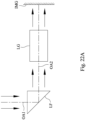
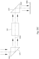
- Fig. 22A is a schematic view of an arrangement of a light path folding element LF in the optical imaging system assembly of the present disclosure.
- Fig. 22B is a schematic view of another arrangement of the light path folding element LF in the optical imaging system assembly of the present disclosure. As shown in Figs.
- the optical imaging system assembly includes, in order from an imaged object (not shown in drawings) to an image surface IMG, a first optical axis OA1, the light path folding element LF and a second optical axis OA2, wherein the light path folding element LF can be disposed between the imaged object and a lens group LG of the optical imaging system assembly as shown in Fig. 22A , or can be disposed between the lens group LG of the optical imaging system assembly and the image surface IMG as shown in Fig. 22B .
- Fig. 22C is a schematic view of an arrangement of two light path folding elements LF1, LF2 in the optical imaging system assembly of the present disclosure. As shown in Fig.
- the optical imaging system assembly includes, in order from an imaged object (not shown in drawings) to an image surface IM, a first optical axis OA1, the light path folding element LF1, a second optical axis OA2, the light path folding element LF2 and a third optical axis OA3, wherein the light path folding element LF1 is disposed between the imaged object and a lens group LG of the optical imaging system assembly, and the light path folding element LF2 is disposed between the lens group LG of the optical imaging system assembly and the image surface IMG.
- the optical imaging system assembly can also be selectively disposed with three or more light path folding element, the type, amount and location of the light path folding element will not be limited to the present disclosure.
- the optical imaging system assembly can include at least one stop, such as an aperture stop, a glare stop or a field stop, for eliminating stray light and thereby improving image resolution thereof.
- at least one stop such as an aperture stop, a glare stop or a field stop, for eliminating stray light and thereby improving image resolution thereof.
- the aperture stop can be configured as a front stop or a middle stop, wherein the front stop indicates that the aperture stop is disposed between an object and the first lens element, and the middle stop indicates that the aperture stop is disposed between the first lens element and the image surface.
- the aperture stop is a front stop
- a longer distance between an exit pupil of the optical imaging system assembly and the image surface can be obtained, and thereby obtains a telecentric effect and improves the image-sensing efficiency of the image sensor, such as CCD or CMOS.
- the middle stop is favorable for enlarging the field of view of the optical imaging system assembly and thereby provides a wider field of view for the same.
- an aperture control unit can be properly configured.
- the aperture control unit can be a mechanical element or a light controlling element, and the dimension and the shape of the aperture control unit can be electrically controlled.
- the mechanical element can include a moveable component such a blade group or a shielding plate.
- the light controlling element can include a screen component such as a light filter, an electrochromic material, a liquid crystal layer or the like.
- the amount of incoming light or the exposure time of the image can be controlled by the aperture control unit to enhance the image moderation ability.
- the aperture control unit can be the aperture stop of the optical imaging system assembly according to the present disclosure, so as to moderate the image quality by changing f-number such as changing the depth of field or the exposure speed.
- the optical imaging system assembly of the present disclosure can be applied to 3D (three-dimensional) image capturing applications, in products such as digital cameras, mobile devices, digital tablets, smart TVs, surveillance systems, motion sensing input devices, driving recording systems, rearview camera systems, wearable devices, unmanned aerial vehicles, and other electronic imaging products.
- products such as digital cameras, mobile devices, digital tablets, smart TVs, surveillance systems, motion sensing input devices, driving recording systems, rearview camera systems, wearable devices, unmanned aerial vehicles, and other electronic imaging products.
- an imaging apparatus including the aforementioned optical imaging system assembly and an image sensor is provided, wherein the image sensor is disposed on the image surface of the optical imaging system assembly.
- the imaging apparatus can further include a barrel member, a holder member or a combination thereof.
- an electronic device including the aforementioned imaging apparatus is provided. Therefore, the image quality can be increased.
- the electronic device can further include a control unit, a display, a storage unit, a random-access memory unit (RAM) or a combination thereof.
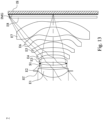
- Fig. 1 is a schematic view of an imaging apparatus 1 according to the 1st embodiment of the present disclosure.
- Fig. 2 shows spherical aberration curves, astigmatic field curves and a distortion curve of the imaging apparatus 1 according to the 1st embodiment.
- the imaging apparatus 1 includes an optical imaging system assembly (its reference numeral is omitted) and an image sensor IS.
- the optical imaging system assembly includes, in order from an object side to an image side along an optical path, an aperture stop ST, a first lens element E1, a second lens element E2, a stop S1, a third lens element E3, a fourth lens element E4, a stop S2, a fifth lens element E5, a sixth lens element E6, a seventh lens element E7, a filter E8 and an image surface IMG, wherein the image sensor IS is disposed on the image surface IMG of the optical imaging system assembly.
- the optical imaging system assembly includes seven lens elements (E1, E2, E3, E4, E5, E6, E7) without additional one or more lens elements inserted between the first lens element E1 and the seventh lens element E7.
- the first lens element E1 with positive refractive power has an object-side surface being convex in a paraxial region thereof and an image-side surface being concave in a paraxial region thereof.
- the first lens element E1 is made of a plastic material, and has the object-side surface and the image-side surface being both aspheric.
- Fig. 17 is a schematic view of partial parameters, the inflection points IP of each lens element and the critical points CP of the sixth lens element E6 and the image-side surface of the seventh lens element E7 according to the 1st embodiment.
- the object-side surface of the first lens element E1 includes one inflection point IP
- the image-side surface of the first lens element E1 includes one inflection point IP.
- the second lens element E2 with negative refractive power has an object-side surface being convex in a paraxial region thereof and an image-side surface being concave in a paraxial region thereof.
- the second lens element E2 is made of a plastic material, and has the object-side surface and the image-side surface being both aspheric. Furthermore, the object-side surface of the second lens element E2 includes two inflection points IP (as shown in Fig. 17 ).
- the third lens element E3 with positive refractive power has an object-side surface being convex in a paraxial region thereof and an image-side surface being concave in a paraxial region thereof.
- the third lens element E3 is made of a plastic material, and has the object-side surface and the image-side surface being both aspheric. Furthermore, the object-side surface of the third lens element E3 includes one inflection point IP (as shown in Fig. 17 ), and the image-side surface of the third lens element E3 includes one inflection point IP (as shown in Fig. 17 ).
- the fourth lens element E4 with negative refractive power has an object-side surface being concave in a paraxial region thereof and an image-side surface being convex in a paraxial region thereof.
- the fourth lens element E4 is made of a plastic material, and has the object-side surface and the image-side surface being both aspheric. Furthermore, the image-side surface of the fourth lens element E4 includes one inflection point IP (as shown in Fig. 17 ).
- the fifth lens element E5 with positive refractive power has an object-side surface being concave in a paraxial region thereof and an image-side surface being convex in a paraxial region thereof.
- the fifth lens element E5 is made of a plastic material, and has the object-side surface and the image-side surface being both aspheric. Furthermore, the object-side surface of the fifth lens element E5 includes two inflection points IP (as shown in Fig. 17 ), and the image-side surface of the fifth lens element E5 includes two inflection points IP (as shown in Fig. 17 ).
- the sixth lens element E6 with negative refractive power has an object-side surface being convex in a paraxial region thereof and an image-side surface being concave in a paraxial region thereof.
- the sixth lens element E6 is made of a plastic material, and has the object-side surface and the image-side surface being both aspheric. Furthermore, the object-side surface of the sixth lens element E6 includes two inflection points IP (as shown in Fig. 17 ) and one critical point CP (as shown in Fig. 17 ) in an off-axis region thereof, and the image-side surface of the sixth lens element E6 includes two inflection points IP (as shown in Fig. 17 ) and one critical point CP (as shown in Fig. 17 ) in an off-axis region thereof.
- the seventh lens element E7 with negative refractive power has an object-side surface being concave in a paraxial region thereof and an image-side surface being concave in a paraxial region thereof.
- the seventh lens element E7 is made of a plastic material, and has the object-side surface and the image-side surface being both aspheric. Furthermore, the object-side surface of the seventh lens element E7 includes one inflection point IP (as shown in Fig. 17 ), and the image-side surface of the seventh lens element E7 includes two inflection points IP (as shown in Fig. 17 ) and one critical point CP (as shown in Fig. 17 ) in an off-axis region thereof.
- the filter E8 is made of a glass material, which is located between the seventh lens element E7 and the image surface IMG in order, and will not affect the focal length of the optical imaging system assembly.
- a central thickness of the first lens element E1 is CT1
- a central thickness of the second lens element E2 is CT2
- a central thickness of the third lens element E3 is CT3
- a central thickness of the fourth lens element E4 is CT4
- a central thickness of the fifth lens element E5 is CT5
- a central thickness of the sixth lens element E6 is CT6
- an axial distance between the first lens element E1 and the second lens element E2 is T12
- an axial distance between the second lens element E2 and the third lens element E3 is T23
- an axial distance between the sixth lens element E6 and the seventh lens element E7 is T67
- an entrance pupil diameter of the optical imaging system assembly is EPD
- the focal length of the optical imaging system assembly is f
- a maximum image height of the optical imaging system assembly is ImgH
- the optical imaging system assembly when the axial distance between the first lens element E1 and the second lens element E2 is T12, the axial distance between the second lens element E2 and the third lens element E3 is T23, an axial distance between the third lens element E3 and the fourth lens element E4 is T34, an axial distance between the fourth lens element E4 and the fifth lens element E5 is T45, an axial distance between the fifth lens element E5 and the sixth lens element E6 is T56, the axial distance between the sixth lens element E6 and the seventh lens element E7 is T67, a sum of all axial distances between adjacent lens elements of the optical imaging system assembly is ⁇ AT, the central thickness of the first lens element E1 is CT1, the central thickness of the second lens element E2 is CT2, the central thickness of the third lens element E3 is CT3, the central thickness of the fourth lens element E4 is CT4, the central thickness of the fifth lens element E5 is CT5, the central thickness of the sixth lens element E6 is CT6, a central thickness of the
- a focal length of the first lens element E1 is f1
- a curvature radius of the object-side surface of the first lens element E1 is R1
- a curvature radius of the image-side surface of the first lens element E1 is R2
- a curvature radius of the object-side surface of the sixth lens element E6 is R11
- a curvature radius of the image-side surface of the sixth lens element E6 is R12
- a focal length of the seventh lens element E7 is f7
- a curvature radius of the object-side surface of the seventh lens element E7 is R13
- a curvature radius of the image-side surface of the seventh lens element E7 is R14
- a distance between the critical point CP of the object-side surface of the sixth lens element E6 and the optical axis is Yc61 (as shown in Fig. 17 )
- a maximum distance between an optical effective region of the object-side surface of the sixth lens element E6 and the optical axis is Y61 (as shown in Fig. 17 )
- a distance between the critical point CP of the image-side surface of the sixth lens element E6 and the optical axis is Yc62 (as shown in Fig. 17 )
- a maximum distance between an optical effective region of the image-side surface of the sixth lens element E6 and the optical axis is Y62 (as shown in Fig.
- Table 1 The detailed optical data of the 1st embodiment are shown in Table 1 and the aspheric surface data are shown in Table 2 below.
- Effective radius of Surface 6 (stop S1) is 1.295 mm. Effective radius of Surface 11 (stop S2) is 2.010 mm.
- Table 2 - Aspheric Coefficients Surface # 2 3 4 5 7 k 1.51234E-01 5.39116E+00 9.46570E+01 2.33650E+00 -9.79790E+01
- Table 1 the curvature radius, the thickness and the focal length are shown in millimeters (mm).
- Surface numbers 0-20 represent the surfaces sequentially arranged from the object side to the image side along the optical axis.
- k represents the conic coefficient of the equation of the aspheric surface profiles.
- A4-A30 represent the aspheric coefficients ranging from the 4th order to the 30th order.
- Fig. 3 is a schematic view of an imaging apparatus 2 according to the 2nd embodiment of the present disclosure.
- Fig. 4 shows spherical aberration curves, astigmatic field curves and a distortion curve of the imaging apparatus 2 according to the 2nd embodiment.
- the imaging apparatus 2 includes an optical imaging system assembly (its reference numeral is omitted) and an image sensor IS.
- the optical imaging system assembly includes, in order from an object side to an image side along an optical path, an aperture stop ST, a first lens element E1, a second lens element E2, a stop S1, a third lens element E3, a fourth lens element E4, a stop S2, a fifth lens element E5, a sixth lens element E6, a seventh lens element E7, a filter E8 and an image surface IMG, wherein the image sensor IS is disposed on the image surface IMG of the optical imaging system assembly.
- the optical imaging system assembly includes seven lens elements (E1, E2, E3, E4, E5, E6, E7) without additional one or more lens elements inserted between the first lens element E1 and the seventh lens element E7.
- the first lens element E1 with positive refractive power has an object-side surface being convex in a paraxial region thereof and an image-side surface being concave in a paraxial region thereof.
- the first lens element E1 is made of a plastic material, and has the object-side surface and the image-side surface being both aspheric. Furthermore, the object-side surface of the first lens element E1 includes one inflection point, and the image-side surface of the first lens element E1 includes one inflection point.
- the second lens element E2 with negative refractive power has an object-side surface being convex in a paraxial region thereof and an image-side surface being concave in a paraxial region thereof.
- the second lens element E2 is made of a plastic material, and has the object-side surface and the image-side surface being both aspheric. Furthermore, the object-side surface of the second lens element E2 includes two inflection points.
- the third lens element E3 with positive refractive power has an object-side surface being convex in a paraxial region thereof and an image-side surface being concave in a paraxial region thereof.
- the third lens element E3 is made of a plastic material, and has the object-side surface and the image-side surface being both aspheric. Furthermore, the object-side surface of the third lens element E3 includes one inflection point, and the image-side surface of the third lens element E3 includes one inflection point.
- the fourth lens element E4 with negative refractive power has an object-side surface being concave in a paraxial region thereof and an image-side surface being convex in a paraxial region thereof.
- the fourth lens element E4 is made of a plastic material, and has the object-side surface and the image-side surface being both aspheric. Furthermore, the image-side surface of the fourth lens element E4 includes one inflection point.
- the fifth lens element E5 with positive refractive power has an object-side surface being concave in a paraxial region thereof and an image-side surface being convex in a paraxial region thereof.
- the fifth lens element E5 is made of a plastic material, and has the object-side surface and the image-side surface being both aspheric. Furthermore, the object-side surface of the fifth lens element E5 includes one inflection point, and the image-side surface of the fifth lens element E5 includes two inflection points.
- the sixth lens element E6 with negative refractive power has an object-side surface being convex in a paraxial region thereof and an image-side surface being concave in a paraxial region thereof.
- the sixth lens element E6 is made of a plastic material, and has the object-side surface and the image-side surface being both aspheric. Furthermore, the object-side surface of the sixth lens element E6 includes two inflection points and one critical point in an off-axis region thereof, and the image-side surface of the sixth lens element E6 includes two inflection points and one critical point in an off-axis region thereof.
- the seventh lens element E7 with negative refractive power has an object-side surface being concave in a paraxial region thereof and an image-side surface being concave in a paraxial region thereof.
- the seventh lens element E7 is made of a plastic material, and has the object-side surface and the image-side surface being both aspheric. Furthermore, the object-side surface of the seventh lens element E7 includes one inflection point, and the image-side surface of the seventh lens element E7 includes two inflection points and one critical point in an off-axis region thereof.
- the filter E8 is made of a glass material, which is located between the seventh lens element E7 and the image surface IMG in order, and will not affect the focal length of the optical imaging system assembly.
- Table 3 The detailed optical data of the 2nd embodiment are shown in Table 3 and the aspheric surface data are shown in Table 4 below.
- Effective radius of Surface 6 (stop S1) is 1.290 mm. Effective radius of Surface 11 (stop S2) is 2.005 mm.
- Table 4 - Aspheric Coefficients Surface # 2 3 4 5 7 k 1.37277E-01 3.84522E+00 9.47611 E+01 4.84260E+00 -8.51358E+01
- A4 1.234039231E-03 -2.104610909E-02 -6.449983813E-02 -5.765899626E-02 -2.974078130E-02
- A6 -6.473681636E-03 1.225595392E-02 8.270002855E-02 5.905345825E-02 -1.362555596E-02
- the equation of the aspheric surface profiles of the aforementioned lens elements is the same as the equation of the 1st embodiment. Also, the definitions of these parameters shown in the following table are the same as those stated in the 1st embodiment with corresponding values for the 2nd embodiment, so an explanation in this regard will not be provided again.
- these parameters can be calculated from Table 3 and Table 4 as the following values and satisfy the following conditions: 2nd Embodiment f [mm] 5.47
- Fig. 5 is a schematic view of an imaging apparatus 3 according to the 3rd embodiment of the present disclosure.
- Fig. 6 shows spherical aberration curves, astigmatic field curves and a distortion curve of the imaging apparatus 3 according to the 3rd embodiment.
- the imaging apparatus 3 includes an optical imaging system assembly (its reference numeral is omitted) and an image sensor IS.
- the optical imaging system assembly includes, in order from an object side to an image side along an optical path, an aperture stop ST, a first lens element E1, a second lens element E2, a stop S1, a third lens element E3, a fourth lens element E4, a stop S2, a fifth lens element E5, a sixth lens element E6, a seventh lens element E7, a filter E8 and an image surface IMG, wherein the image sensor IS is disposed on the image surface IMG of the optical imaging system assembly.
- the optical imaging system assembly includes seven lens elements (E1, E2, E3, E4, E5, E6, E7) without additional one or more lens elements inserted between the first lens element E1 and the seventh lens element E7.
- the first lens element E1 with positive refractive power has an object-side surface being convex in a paraxial region thereof and an image-side surface being concave in a paraxial region thereof.
- the first lens element E1 is made of a glass material, and has the object-side surface and the image-side surface being both aspheric. Furthermore, the image-side surface of the first lens element E1 includes one inflection point.
- the second lens element E2 with negative refractive power has an object-side surface being convex in a paraxial region thereof and an image-side surface being concave in a paraxial region thereof.
- the second lens element E2 is made of a plastic material, and has the object-side surface and the image-side surface being both aspheric. Furthermore, the object-side surface of the second lens element E2 includes two inflection points.
- the third lens element E3 with positive refractive power has an object-side surface being convex in a paraxial region thereof and an image-side surface being convex in a paraxial region thereof.
- the third lens element E3 is made of a plastic material, and has the object-side surface and the image-side surface being both aspheric. Furthermore, the object-side surface of the third lens element E3 includes one inflection point.
- the fourth lens element E4 with negative refractive power has an object-side surface being concave in a paraxial region thereof and an image-side surface being concave in a paraxial region thereof.
- the fourth lens element E4 is made of a plastic material, and has the object-side surface and the image-side surface being both aspheric. Furthermore, the image-side surface of the fourth lens element E4 includes two inflection points.
- the fifth lens element E5 with positive refractive power has an object-side surface being concave in a paraxial region thereof and an image-side surface being convex in a paraxial region thereof.
- the fifth lens element E5 is made of a plastic material, and has the object-side surface and the image-side surface being both aspheric. Furthermore, the object-side surface of the fifth lens element E5 includes one inflection point, and the image-side surface of the fifth lens element E5 includes two inflection points.
- the sixth lens element E6 with negative refractive power has an object-side surface being convex in a paraxial region thereof and an image-side surface being concave in a paraxial region thereof.
- the sixth lens element E6 is made of a plastic material, and has the object-side surface and the image-side surface being both aspheric. Furthermore, the object-side surface of the sixth lens element E6 includes two inflection points and one critical point in an off-axis region thereof, and the image-side surface of the sixth lens element E6 includes two inflection points and one critical point in an off-axis region thereof.
- the seventh lens element E7 with negative refractive power has an object-side surface being concave in a paraxial region thereof and an image-side surface being concave in a paraxial region thereof.
- the seventh lens element E7 is made of a plastic material, and has the object-side surface and the image-side surface being both aspheric. Furthermore, the object-side surface of the seventh lens element E7 includes one inflection point, and the image-side surface of the seventh lens element E7 includes two inflection points and one critical point in an off-axis region thereof.
- the filter E8 is made of a glass material, which is located between the seventh lens element E7 and the image surface IMG in order, and will not affect the focal length of the optical imaging system assembly.
- Table 5 The detailed optical data of the 3rd embodiment are shown in Table 5 and the aspheric surface data are shown in Table 6 below.
- Effective radius of Surface 6 (stop S1) is 1.290 mm. Effective radius of Surface 11 (stop S2) is 2.010 mm.
- Table 6 - Aspheric Coefficients Surface # 2 3 4 5 7 k 1.52001E-01 5.18426E+00 9.53723E+01 3.91520E+00 -9.83524E+01
- A4 4.142552555E-04 -1.727853311E-02 -5.612683107E-02 -4.959720118E-02 -3.639368770E-02
- A6 -2.846351912E-03 1.239138449E-02 7.322828872E-02 5.115420865E-02 -5.255879631E-03
- the equation of the aspheric surface profiles of the aforementioned lens elements is the same as the equation of the 1st embodiment. Also, the definitions of these parameters shown in the following table are the same as those stated in the 1st embodiment with corresponding values for the 3rd embodiment, so an explanation in this regard will not be provided again.
- these parameters can be calculated from Table 5 and Table 6 as the following values and satisfy the following conditions: 3rd Embodiment f [mm] 5.45
- Fig. 7 is a schematic view of an imaging apparatus 4 according to the 4th embodiment of the present disclosure.
- Fig. 8 shows spherical aberration curves, astigmatic field curves and a distortion curve of the imaging apparatus 4 according to the 4th embodiment.
- the imaging apparatus 4 includes an optical imaging system assembly (its reference numeral is omitted) and an image sensor IS.
- the optical imaging system assembly includes, in order from an object side to an image side along an optical path, an aperture stop ST, a first lens element E1, a second lens element E2, a stop S1, a third lens element E3, a fourth lens element E4, a fifth lens element E5, a sixth lens element E6, a seventh lens element E7, a filter E8 and an image surface IMG, wherein the image sensor IS is disposed on the image surface IMG of the optical imaging system assembly.
- the optical imaging system assembly includes seven lens elements (E1, E2, E3, E4, E5, E6, E7) without additional one or more lens elements inserted between the first lens element E1 and the seventh lens element E7.
- the first lens element E1 with positive refractive power has an object-side surface being convex in a paraxial region thereof and an image-side surface being concave in a paraxial region thereof.
- the first lens element E1 is made of a plastic material, and has the object-side surface and the image-side surface being both aspheric.
- the second lens element E2 with negative refractive power has an object-side surface being convex in a paraxial region thereof and an image-side surface being concave in a paraxial region thereof.
- the second lens element E2 is made of a plastic material, and has the object-side surface and the image-side surface being both aspheric. Furthermore, the object-side surface of the second lens element E2 includes two inflection points.
- the third lens element E3 with positive refractive power has an object-side surface being convex in a paraxial region thereof and an image-side surface being concave in a paraxial region thereof.
- the third lens element E3 is made of a plastic material, and has the object-side surface and the image-side surface being both aspheric. Furthermore, the object-side surface of the third lens element E3 includes one inflection point, and the image-side surface of the third lens element E3 includes one inflection point.
- the fourth lens element E4 with negative refractive power has an object-side surface being concave in a paraxial region thereof and an image-side surface being convex in a paraxial region thereof.
- the fourth lens element E4 is made of a plastic material, and has the object-side surface and the image-side surface being both aspheric. Furthermore, the image-side surface of the fourth lens element E4 includes one inflection point.
- the fifth lens element E5 with positive refractive power has an object-side surface being concave in a paraxial region thereof and an image-side surface being convex in a paraxial region thereof.
- the fifth lens element E5 is made of a plastic material, and has the object-side surface and the image-side surface being both aspheric. Furthermore, the object-side surface of the fifth lens element E5 includes two inflection points, and the image-side surface of the fifth lens element E5 includes two inflection points.
- the sixth lens element E6 with negative refractive power has an object-side surface being convex in a paraxial region thereof and an image-side surface being concave in a paraxial region thereof.
- the sixth lens element E6 is made of a plastic material, and has the object-side surface and the image-side surface being both aspheric. Furthermore, the object-side surface of the sixth lens element E6 includes two inflection points and one critical point in an off-axis region thereof, and the image-side surface of the sixth lens element E6 includes two inflection points and one critical point in an off-axis region thereof.
- the seventh lens element E7 with negative refractive power has an object-side surface being concave in a paraxial region thereof and an image-side surface being concave in a paraxial region thereof.
- the seventh lens element E7 is made of a plastic material, and has the object-side surface and the image-side surface being both aspheric. Furthermore, the object-side surface of the seventh lens element E7 includes one inflection point, and the image-side surface of the seventh lens element E7 includes two inflection points and one critical point in an off-axis region thereof.
- the filter E8 is made of a glass material, which is located between the seventh lens element E7 and the image surface IMG in order, and will not affect the focal length of the optical imaging system assembly.
- Table 7 The detailed optical data of the 4th embodiment are shown in Table 7 and the aspheric surface data are shown in Table 8 below.
- Effective radius of Surface 6 (stop S1) is 2.06 mm.
- A4 -2.168082465E-04 -3.763223132E-03 -1.418254226E-02 -1.472000880E-02 -7.581401865E-03
- A6 2.239675357E-04 2.215214259E-04 5.926003575E-03 7.312644566E-03 -1.694524157E-03
- A8 -1.269460556E-04 6.219427978E-04 -1.409847517E-03 -2.491672506E-03 1.599373746E-03
- A10 4.296367941E-05 -4.267013351E-04 3.000800762E-04 8.558709957E-04
- the equation of the aspheric surface profiles of the aforementioned lens elements is the same as the equation of the 1st embodiment. Also, the definitions of these parameters shown in the following table are the same as those stated in the 1st embodiment with corresponding values for the 4th embodiment, so an explanation in this regard will not be provided again.
- these parameters can be calculated from Table 7 and Table 8 as the following values and satisfy the following conditions: 4th Embodiment f [mm] 8.71
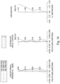
- Fig. 9 is a schematic view of an imaging apparatus 5 according to the 5th embodiment of the present disclosure.
- Fig. 10 shows spherical aberration curves, astigmatic field curves and a distortion curve of the imaging apparatus 5 according to the 5th embodiment.
- the imaging apparatus 5 includes an optical imaging system assembly (its reference numeral is omitted) and an image sensor IS.
- the optical imaging system assembly includes, in order from an object side to an image side along an optical path, an aperture stop ST, a first lens element E1, a second lens element E2, a stop S1, a third lens element E3, a fourth lens element E4, a stop S2, a fifth lens element E5, a sixth lens element E6, a seventh lens element E7, a filter E8 and an image surface IMG, wherein the image sensor IS is disposed on the image surface IMG of the optical imaging system assembly.
- the optical imaging system assembly includes seven lens elements (E1, E2, E3, E4, E5, E6, E7) without additional one or more lens elements inserted between the first lens element E1 and the seventh lens element E7.
- the first lens element E1 with positive refractive power has an object-side surface being convex in a paraxial region thereof and an image-side surface being concave in a paraxial region thereof.
- the first lens element E1 is made of a plastic material, and has the object-side surface and the image-side surface being both aspheric. Furthermore, the object-side surface of the first lens element E1 includes one inflection point, and the image-side surface of the first lens element E1 includes one inflection point.
- the second lens element E2 with negative refractive power has an object-side surface being convex in a paraxial region thereof and an image-side surface being concave in a paraxial region thereof.
- the second lens element E2 is made of a plastic material, and has the object-side surface and the image-side surface being both aspheric. Furthermore, the object-side surface of the second lens element E2 includes two inflection points.
- the third lens element E3 with negative refractive power has an object-side surface being convex in a paraxial region thereof and an image-side surface being concave in a paraxial region thereof.
- the third lens element E3 is made of a plastic material, and has the object-side surface and the image-side surface being both aspheric. Furthermore, the object-side surface of the third lens element E3 includes one inflection point, and the image-side surface of the third lens element E3 includes one inflection point.
- the fourth lens element E4 with positive refractive power has an object-side surface being convex in a paraxial region thereof and an image-side surface being concave in a paraxial region thereof.
- the fourth lens element E4 is made of a plastic material, and has the object-side surface and the image-side surface being both aspheric. Furthermore, the object-side surface of the fourth lens element E4 includes one inflection point, and the image-side surface of the fourth lens element E4 includes two inflection points.
- the fifth lens element E5 with positive refractive power has an object-side surface being concave in a paraxial region thereof and an image-side surface being convex in a paraxial region thereof.
- the fifth lens element E5 is made of a plastic material, and has the object-side surface and the image-side surface being both aspheric. Furthermore, the object-side surface of the fifth lens element E5 includes two inflection points, and the image-side surface of the fifth lens element E5 includes two inflection points.
- the sixth lens element E6 with negative refractive power has an object-side surface being convex in a paraxial region thereof and an image-side surface being concave in a paraxial region thereof.
- the sixth lens element E6 is made of a plastic material, and has the object-side surface and the image-side surface being both aspheric. Furthermore, the object-side surface of the sixth lens element E6 includes two inflection points and one critical point in an off-axis region thereof, and the image-side surface of the sixth lens element E6 includes two inflection points and one critical point in an off-axis region thereof.
- the seventh lens element E7 with negative refractive power has an object-side surface being concave in a paraxial region thereof and an image-side surface being concave in a paraxial region thereof.
- the seventh lens element E7 is made of a plastic material, and has the object-side surface and the image-side surface being both aspheric. Furthermore, the object-side surface of the seventh lens element E7 includes one inflection point, and the image-side surface of the seventh lens element E7 includes one inflection point and one critical point in an off-axis region thereof.
- the filter E8 is made of a glass material, which is located between the seventh lens element E7 and the image surface IMG in order, and will not affect the focal length of the optical imaging system assembly.
- Table 9 The detailed optical data of the 5th embodiment are shown in Table 9 and the aspheric surface data are shown in Table 10 below.
- Effective radius of Surface 6 (stop S1) is 1.285 mm. Effective radius of Surface 11 (stop S2) is 2.000 mm.
- Table 10 - Aspheric Coefficients Surface # 2 3 4 5 7 k 3.88221E-02 -3.85864E+00 9.33827E+01 7.66443E+00 -8.92496E+01
- A4 -1.302602543E-03 -1.843688353E-02 -6.218797748E-02 -5.312952999E-02 -3.509645726E-02
- the equation of the aspheric surface profiles of the aforementioned lens elements is the same as the equation of the 1st embodiment. Also, the definitions of these parameters shown in the following table are the same as those stated in the 1st embodiment with corresponding values for the 5th embodiment, so an explanation in this regard will not be provided again.
- Fig. 11 is a schematic view of an imaging apparatus 6 according to the 6th embodiment of the present disclosure.
- Fig. 12 shows spherical aberration curves, astigmatic field curves and a distortion curve of the imaging apparatus 6 according to the 6th embodiment.
- the imaging apparatus 6 includes an optical imaging system assembly (its reference numeral is omitted) and an image sensor IS.
- the optical imaging system assembly includes, in order from an object side to an image side along an optical path, an aperture stop ST, a first lens element E1, a second lens element E2, a stop S1, a third lens element E3, a fourth lens element E4, a stop S2, a fifth lens element E5, a sixth lens element E6, a seventh lens element E7, a filter E8 and an image surface IMG, wherein the image sensor IS is disposed on the image surface IMG of the optical imaging system assembly.
- the optical imaging system assembly includes seven lens elements (E1, E2, E3, E4, E5, E6, E7) without additional one or more lens elements inserted between the first lens element E1 and the seventh lens element E7.
- the first lens element E1 with positive refractive power has an object-side surface being convex in a paraxial region thereof and an image-side surface being concave in a paraxial region thereof.
- the first lens element E1 is made of a plastic material, and has the object-side surface and the image-side surface being both aspheric. Furthermore, the image-side surface of the first lens element E1 includes one inflection point.
- the second lens element E2 with negative refractive power has an object-side surface being concave in a paraxial region thereof and an image-side surface being concave in a paraxial region thereof.
- the second lens element E2 is made of a plastic material, and has the object-side surface and the image-side surface being both aspheric. Furthermore, the object-side surface of the second lens element E2 includes one inflection point.
- the third lens element E3 with positive refractive power has an object-side surface being convex in a paraxial region thereof and an image-side surface being concave in a paraxial region thereof.
- the third lens element E3 is made of a plastic material, and has the object-side surface and the image-side surface being both aspheric. Furthermore, the object-side surface of the third lens element E3 includes one inflection point, and the image-side surface of the third lens element E3 includes one inflection point.
- the fourth lens element E4 with negative refractive power has an object-side surface being concave in a paraxial region thereof and an image-side surface being convex in a paraxial region thereof.
- the fourth lens element E4 is made of a plastic material, and has the object-side surface and the image-side surface being both aspheric. Furthermore, the image-side surface of the fourth lens element E4 includes one inflection point.
- the fifth lens element E5 with positive refractive power has an object-side surface being concave in a paraxial region thereof and an image-side surface being convex in a paraxial region thereof.
- the fifth lens element E5 is made of a plastic material, and has the object-side surface and the image-side surface being both aspheric. Furthermore, the object-side surface of the fifth lens element E5 includes two inflection points, and the image-side surface of the fifth lens element E5 includes two inflection points.
- the sixth lens element E6 with negative refractive power has an object-side surface being convex in a paraxial region thereof and an image-side surface being concave in a paraxial region thereof.
- the sixth lens element E6 is made of a plastic material, and has the object-side surface and the image-side surface being both aspheric. Furthermore, the object-side surface of the sixth lens element E6 includes two inflection points and one critical point in an off-axis region thereof, and the image-side surface of the sixth lens element E6 includes two inflection points and one critical point in an off-axis region thereof.
- the seventh lens element E7 with negative refractive power has an object-side surface being concave in a paraxial region thereof and an image-side surface being concave in a paraxial region thereof.
- the seventh lens element E7 is made of a plastic material, and has the object-side surface and the image-side surface being both aspheric. Furthermore, the object-side surface of the seventh lens element E7 includes one inflection point, and the image-side surface of the seventh lens element E7 includes two inflection points and one critical point in an off-axis region thereof.
- the filter E8 is made of a glass material, which is located between the seventh lens element E7 and the image surface IMG in order, and will not affect the focal length of the optical imaging system assembly.
- Table 11 The detailed optical data of the 6th embodiment are shown in Table 11 and the aspheric surface data are shown in Table 12 below.
- Effective radius of Surface 6 (stop S1) is 1.290 mm. Effective radius of Surface 11 (stop S2) is 2.000 mm.
- Table 12 - Aspheric Coefficients Surface # 2 3 4 5 7 k 1.53610E-01 2.64119E+00 9.90000E+01 7.61787E+00 -8.60495E+01
- A4 -2.593426927E-03 -1.847536646E-02 -6.666414585E-02 -6.391954072E-02 -3.376492983E-02
- A6 4.239389934E-03 4.382980914E-03 1.000761185E-01 9.261502217E-02 -1.705859464E-02
- the equation of the aspheric surface profiles of the aforementioned lens elements is the same as the equation of the 1st embodiment. Also, the definitions of these parameters shown in the following table are the same as those stated in the 1st embodiment with corresponding values for the 6th embodiment, so an explanation in this regard will not be provided again.
- these parameters can be calculated from Table 11 and Table 12 as the following values and satisfy the following conditions: 6th Embodiment f [mm] 5.34
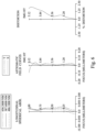
- Fig. 13 is a schematic view of an imaging apparatus 7 according to the 7th embodiment of the present disclosure.
- Fig. 14 shows spherical aberration curves, astigmatic field curves and a distortion curve of the imaging apparatus 7 according to the 7th embodiment.
- the imaging apparatus 7 includes an optical imaging system assembly (its reference numeral is omitted) and an image sensor IS.
- the optical imaging system assembly includes, in order from an object side to an image side along an optical path, an aperture stop ST, a first lens element E1, a second lens element E2, a stop S1, a third lens element E3, a fourth lens element E4, a fifth lens element E5, a sixth lens element E6, a seventh lens element E7, a filter E8 and an image surface IMG, wherein the image sensor IS is disposed on the image surface IMG of the optical imaging system assembly.
- the optical imaging system assembly includes seven lens elements (E1, E2, E3, E4, E5, E6, E7) without additional one or more lens elements inserted between the first lens element E1 and the seventh lens element E7.
- the first lens element E1 with positive refractive power has an object-side surface being convex in a paraxial region thereof and an image-side surface being concave in a paraxial region thereof.
- the first lens element E1 is made of a plastic material, and has the object-side surface and the image-side surface being both aspheric. Furthermore, the object-side surface of the first lens element E1 includes one inflection point, and the image-side surface of the first lens element E1 includes one inflection point.
- the second lens element E2 with negative refractive power has an object-side surface being convex in a paraxial region thereof and an image-side surface being concave in a paraxial region thereof.
- the second lens element E2 is made of a plastic material, and has the object-side surface and the image-side surface being both aspheric. Furthermore, the object-side surface of the second lens element E2 includes two inflection points.
- the third lens element E3 with positive refractive power has an object-side surface being convex in a paraxial region thereof and an image-side surface being concave in a paraxial region thereof.
- the third lens element E3 is made of a plastic material, and has the object-side surface and the image-side surface being both aspheric. Furthermore, the object-side surface of the third lens element E3 includes one inflection point, and the image-side surface of the third lens element E3 includes one inflection point.
- the fourth lens element E4 with negative refractive power has an object-side surface being concave in a paraxial region thereof and an image-side surface being convex in a paraxial region thereof.
- the fourth lens element E4 is made of a plastic material, and has the object-side surface and the image-side surface being both aspheric. Furthermore, the image-side surface of the fourth lens element E4 includes one inflection point.
- the fifth lens element E5 with positive refractive power has an object-side surface being concave in a paraxial region thereof and an image-side surface being convex in a paraxial region thereof.
- the fifth lens element E5 is made of a plastic material, and has the object-side surface and the image-side surface being both aspheric. Furthermore, the object-side surface of the fifth lens element E5 includes one inflection point, and the image-side surface of the fifth lens element E5 includes two inflection points.
- the sixth lens element E6 with negative refractive power has an object-side surface being convex in a paraxial region thereof and an image-side surface being concave in a paraxial region thereof.
- the sixth lens element E6 is made of a plastic material, and has the object-side surface and the image-side surface being both aspheric. Furthermore, the object-side surface of the sixth lens element E6 includes two inflection points and one critical point in an off-axis region thereof, and the image-side surface of the sixth lens element E6 includes two inflection points and one critical point in an off-axis region thereof.
- the seventh lens element E7 with negative refractive power has an object-side surface being concave in a paraxial region thereof and an image-side surface being concave in a paraxial region thereof.
- the seventh lens element E7 is made of a plastic material, and has the object-side surface and the image-side surface being both aspheric. Furthermore, the object-side surface of the seventh lens element E7 includes one inflection point, and the image-side surface of the seventh lens element E7 includes one inflection point and one critical point in an off-axis region thereof.
- the filter E8 is made of a glass material, which is located between the seventh lens element E7 and the image surface IMG in order, and will not affect the focal length of the optical imaging system assembly.
- Table 13 The detailed optical data of the 7th embodiment are shown in Table 13 and the aspheric surface data are shown in Table 14 below.
- Effective radius of Surface 6 (stop S1) is 1.33 mm.
- Table 14 - Aspheric Coefficients Surface # 2 3 4 5 7 k 1.38095E-01 5.73555E+00 9.21025E+01 4.16531E+00 -9.24627E+01
- A4 -4.878668882E-04 -1.561322881E-02 -5.863163019E-02 -5.262760502E-02 -2.841561624E-02
- A6 -1.852439215E-03 5.679142995E-03 8.099605699E-02 5.766597361E-02 -1.593346134E-02
- A8 4.917504139E-03 8.247440783E-04 -8.619898698E-02 -2.515881628E-02 3.186326477E-02
- A10 -4.512382927E-03 -7.989868885E-04 7.673489727E-02
- the equation of the aspheric surface profiles of the aforementioned lens elements is the same as the equation of the 1st embodiment. Also, the definitions of these parameters shown in the following table are the same as those stated in the 1st embodiment with corresponding values for the 7th embodiment, so an explanation in this regard will not be provided again.
- Fig. 15 is a schematic view of an imaging apparatus 8 according to the 8th embodiment of the present disclosure.
- Fig. 16 shows spherical aberration curves, astigmatic field curves and a distortion curve of the imaging apparatus 8 according to the 8th embodiment.
- the imaging apparatus 8 includes an optical imaging system assembly (its reference numeral is omitted) and an image sensor IS.
- the optical imaging system assembly includes, in order from an object side to an image side along an optical path, an aperture stop ST, a first lens element E1, a second lens element E2, a stop S1, a third lens element E3, a fourth lens element E4, a stop S2, a fifth lens element E5, a sixth lens element E6, a seventh lens element E7, a filter E8 and an image surface IMG, wherein the image sensor IS is disposed on the image surface IMG of the optical imaging system assembly.
- the optical imaging system assembly includes seven lens elements (E1, E2, E3, E4, E5, E6, E7) without additional one or more lens elements inserted between the first lens element E1 and the seventh lens element E7.
- the first lens element E1 with positive refractive power has an object-side surface being convex in a paraxial region thereof and an image-side surface being concave in a paraxial region thereof.
- the first lens element E1 is made of a plastic material, and has the object-side surface and the image-side surface being both aspheric. Furthermore, the image-side surface of the first lens element E1 includes one inflection point.
- the second lens element E2 with negative refractive power has an object-side surface being convex in a paraxial region thereof and an image-side surface being concave in a paraxial region thereof.
- the second lens element E2 is made of a plastic material, and has the object-side surface and the image-side surface being both aspheric. Furthermore, the object-side surface of the second lens element E2 includes two inflection points.
- the third lens element E3 with positive refractive power has an object-side surface being convex in a paraxial region thereof and an image-side surface being concave in a paraxial region thereof.
- the third lens element E3 is made of a plastic material, and has the object-side surface and the image-side surface being both aspheric. Furthermore, the object-side surface of the third lens element E3 includes one inflection point, and the image-side surface of the third lens element E3 includes one inflection point.
- the fourth lens element E4 with positive refractive power has an object-side surface being convex in a paraxial region thereof and an image-side surface being convex in a paraxial region thereof.
- the fourth lens element E4 is made of a plastic material, and has the object-side surface and the image-side surface being both aspheric. Furthermore, the object-side surface of the fourth lens element E4 includes one inflection point, and the image-side surface of the fourth lens element E4 includes one inflection point.
- the fifth lens element E5 with positive refractive power has an object-side surface being concave in a paraxial region thereof and an image-side surface being convex in a paraxial region thereof.
- the fifth lens element E5 is made of a plastic material, and has the object-side surface and the image-side surface being both aspheric. Furthermore, the image-side surface of the fifth lens element E5 includes two inflection points.
- the sixth lens element E6 with negative refractive power has an object-side surface being convex in a paraxial region thereof and an image-side surface being concave in a paraxial region thereof.
- the sixth lens element E6 is made of a plastic material, and has the object-side surface and the image-side surface being both aspheric. Furthermore, the object-side surface of the sixth lens element E6 includes two inflection points and one critical point in an off-axis region thereof, and the image-side surface of the sixth lens element E6 includes two inflection points and one critical point in an off-axis region thereof.
- the seventh lens element E7 with negative refractive power has an object-side surface being concave in a paraxial region thereof and an image-side surface being concave in a paraxial region thereof.
- the seventh lens element E7 is made of a plastic material, and has the object-side surface and the image-side surface being both aspheric. Furthermore, the object-side surface of the seventh lens element E7 includes one inflection point, and the image-side surface of the seventh lens element E7 includes two inflection points and one critical point in an off-axis region thereof.
- the filter E8 is made of a glass material, which is located between the seventh lens element E7 and the image surface IMG in order, and will not affect the focal length of the optical imaging system assembly.
- Table 15 The detailed optical data of the 8th embodiment are shown in Table 15 and the aspheric surface data are shown in Table 16 below.
- Effective radius of Surface 6 (stop S1) is 1.300 mm. Effective radius of Surface 11 (stop S2) is 2.000 mm.
- Table 16 - Aspheric Coefficients Surface # 2 3 4 5 7 k 2.03285E-01 8.98050E+00 9.73410E+01 5.84598E+00 -9.27762E+01
- A4 1.738775959E-03 -1.870901198E-02 -5.749579011E-02 -6.154235219E-02 -4.960974924E-02
- A6 -5.954807375E-03 1.816025759E-02 7.104715117E-02 7.731895312E-02 1.588132616E-02
- A8 9.771430160E-03 -2.074197600E-02 -4.791732147E-02 -5.282667387E-02 -2.3370755E-02
- A10 -7.572205566E-03 2.2853517
- the equation of the aspheric surface profiles of the aforementioned lens elements is the same as the equation of the 1st embodiment. Also, the definitions of these parameters shown in the following table are the same as those stated in the 1st embodiment with corresponding values for the 8th embodiment, so an explanation in this regard will not be provided again.
- Fig. 18 is a schematic view of an imaging apparatus 100 according to the 9th embodiment of the present disclosure.
- the imaging apparatus 100 of the 9th embodiment is a camera module
- the imaging apparatus 100 includes an imaging lens assembly 101, a driving apparatus 102 and an image sensor 103
- the imaging lens assembly 101 includes the optical imaging system assembly of the present disclosure and a lens barrel (not shown in drawings) for carrying the optical imaging system assembly.
- the imaging apparatus 100 can focus light from an imaged object via the imaging lens assembly 101, perform image focusing by the driving apparatus 102, and generate an image on the image sensor 103, and the imaging information can be transmitted.
- the driving apparatus 102 can be an auto-focus module, which can be driven by driving systems, such as voice coil motors (VCM), micro electro-mechanical systems (MEMS), piezoelectric systems, and shape memory alloys etc.
- VCM voice coil motors
- MEMS micro electro-mechanical systems
- the optical imaging system assembly can obtain a favorable imaging position by the driving apparatus 102 so as to capture clear images when the imaged object is disposed at different object distances.
- the imaging apparatus 100 can include the image sensor 103 located on the image surface of the optical imaging system assembly, such as CMOS and CCD, with superior photosensitivity and low noise. Thus, it is favorable for providing realistic images with high definition image quality thereof.
- the imaging apparatus 100 can further include an image stabilization module 104, which can be a kinetic energy sensor, such as an accelerometer, a gyro sensor, and a Hall Effect sensor.
- the image stabilization module 104 is a gyro sensor, but is not limited thereto. Therefore, the variation of different axial directions of the optical imaging system assembly can adjusted so as to compensate the image blur generated by motion at the moment of exposure, and it is further favorable for enhancing the image quality while photographing in motion and low light situation.
- advanced image compensation functions such as optical image stabilizations (OIS) and electronic image stabilizations (EIS) etc., can be provided.
- Fig. 19A is a schematic view of one side of an electronic device 200 according to the 10th embodiment of the present disclosure.
- Fig. 19B is a schematic view of another side of the electronic device 200 of Fig. 19A .
- Fig. 19C is a system schematic view of the electronic device 200 of Fig. 19A .
- the electronic device 200 according to the 10th embodiment is a smartphone, which include imaging apparatuses 100, 110, 120, 130, 140, a flash module 201, a focusing assisting module 202, an image signal processor (ISP) 203, a user interface 204 and an image software processor 205, wherein each of the imaging apparatuses 120, 130, 140 is a front camera.
- ISP image signal processor
- the electronic device 200 When the user captures images of an imaged object 206 via the user interface 204, the electronic device 200 focuses and generates an image via at least one of the imaging apparatuses 100, 110, 120, 130, 140, while compensating for low illumination via the flash module 201 when necessary. Then, the electronic device 200 quickly focuses on the imaged object 206 according to its object distance information provided by the focusing assisting module 202, and optimizes the image via the image signal processor 203 and the image software processor 205. Thus, the image quality can be further enhanced.
- the focusing assisting module 202 can adopt conventional infrared or laser for obtaining quick focusing, and the user interface 204 can utilize a touch screen or a physical button for capturing and processing the image with various functions of the image processing software.
- Each of the imaging apparatuses 100, 110, 120, 130, 140 according to the 10th embodiment can include the optical imaging system assembly of the present disclosure, and can be the same or similar to the imaging apparatus 100 according to the aforementioned 9th embodiment, and will not describe again herein.
- the imaging apparatuses 100, 110 can be wide angle imaging apparatus and ultra-wide angle imaging apparatus, respectively.
- the imaging apparatuses 120, 130, 140 can be wide angle imaging apparatus, ultra-wide angle imaging apparatus and TOF (Time-Of-Flight) module, respectively, or can be others imaging apparatuses, which will not be limited thereto.
- the connecting relationships between each of the imaging apparatuses 110, 120, 130, 140 and other elements can be the same as the imaging apparatus 100 in Fig. 19C , or can be adaptively adjusted according to the type of the imaging apparatuses, which will not be shown and detailed descripted again.
- Fig. 20 is a schematic view of one side of an electronic device 300 according to the 11th embodiment of the present disclosure.
- the electronic device 300 is a smartphone, which include imaging apparatuses 310, 320, 330 and a flash module 301.
- the electronic device 300 according to the 11th embodiment can include the same or similar elements to that according to the 10th embodiment, and each of the imaging apparatuses 310, 320, 330 according to the 11th embodiment can have a configuration which is the same or similar to that according to the 10th embodiment, and will not describe again herein.
- each of the imaging apparatuses 310, 320, 330 can include the optical imaging system assembly of the present disclosure, and can be the same or similar to the imaging apparatus 100 according to the aforementioned 9th embodiment, and will not describe again herein.
- the imaging apparatus 310 can be ultra-wide angle imaging apparatus
- the imaging apparatus 320 can be wide angle imaging apparatus
- the imaging apparatus 330 can be telephoto imaging apparatus (which can include light path folding element), or can be adaptively adjusted according to the type of the imaging apparatuses, which will not be limited to the arrangement.
- Fig. 21 is a schematic view of one side of an electronic device 400 according to the 12th embodiment of the present disclosure.
- the electronic device 400 is a smartphone, which include imaging apparatuses 410, 420, 430, 440, 450, 460, 470, 480, 490 and a flash module 401.
- the electronic device 400 according to the 12th embodiment can include the same or similar elements to that according to the 10th embodiment, and each of the imaging apparatuses 410, 420, 430, 440, 450, 460, 470, 480, 490 and the flash module 401 can have a configuration which is the same or similar to that according to the 10th embodiment, and will not describe again herein.
- each of the imaging apparatuses 410, 420, 430, 440, 450, 460, 470, 480, 490 can include the optical imaging system assembly of the present disclosure, and can be the same or similar to the imaging apparatus 100 according to the aforementioned 9th embodiment, and will not describe again herein.
- each of the imaging apparatuses 410, 420 can be ultra-wide angle imaging apparatus
- each of the imaging apparatuses 430, 440 can be wide angle imaging apparatus
- each of the imaging apparatuses 450, 460 can be telephoto imaging apparatus
- each of the imaging apparatuses 470, 480 can be telephoto imaging apparatus (which can include light path folding element)
- the imaging apparatus 490 can be TOF module , or can be adaptively adjusted according to the type of the imaging apparatuses, which will not be limited to the arrangement.
Landscapes
- Physics & Mathematics (AREA)
- General Physics & Mathematics (AREA)
- Optics & Photonics (AREA)
- Lenses (AREA)
Applications Claiming Priority (1)
| Application Number | Priority Date | Filing Date | Title |
|---|---|---|---|
| TW110133479A TWI800919B (zh) | 2021-09-08 | 2021-09-08 | 光學成像系統組、取像裝置及電子裝置 |
Publications (1)
| Publication Number | Publication Date |
|---|---|
| EP4148478A1 true EP4148478A1 (de) | 2023-03-15 |
Family
ID=81984822
Family Applications (1)
| Application Number | Title | Priority Date | Filing Date |
|---|---|---|---|
| EP22177853.3A Pending EP4148478A1 (de) | 2021-09-08 | 2022-06-08 | Optische abbildungssystemanordnung, abbildungsgerät und elektronische vorrichtung |
Country Status (4)
| Country | Link |
|---|---|
| US (1) | US20230070553A1 (de) |
| EP (1) | EP4148478A1 (de) |
| CN (1) | CN115774321A (de) |
| TW (1) | TWI800919B (de) |
Citations (3)
| Publication number | Priority date | Publication date | Assignee | Title |
|---|---|---|---|---|
| US20160241756A1 (en) * | 2015-02-17 | 2016-08-18 | Largan Precision Co., Ltd. | Photographing system, image capturing unit and electronic device |
| US20190154974A1 (en) * | 2017-11-23 | 2019-05-23 | Largan Precision Co.,Ltd. | Optical imaging lens assembly, image capturing unit and electronic device |
| CN112748535A (zh) * | 2020-12-29 | 2021-05-04 | 常州市瑞泰光电有限公司 | 摄像光学镜头 |
Family Cites Families (3)
| Publication number | Priority date | Publication date | Assignee | Title |
|---|---|---|---|---|
| US10018805B2 (en) * | 2013-10-14 | 2018-07-10 | Samsung Electro-Mechanics Co., Ltd. | Lens module |
| TWI631382B (zh) * | 2017-07-19 | 2018-08-01 | 大立光電股份有限公司 | 攝像系統透鏡組、取像裝置及電子裝置 |
| TWI683126B (zh) * | 2019-04-02 | 2020-01-21 | 大陸商信泰光學(深圳)有限公司 | 成像鏡頭(三十五) |
-
2021
- 2021-09-08 TW TW110133479A patent/TWI800919B/zh active
- 2021-11-12 CN CN202111340743.XA patent/CN115774321A/zh active Pending
-
2022
- 2022-04-12 US US17/718,445 patent/US20230070553A1/en active Pending
- 2022-06-08 EP EP22177853.3A patent/EP4148478A1/de active Pending
Patent Citations (3)
| Publication number | Priority date | Publication date | Assignee | Title |
|---|---|---|---|---|
| US20160241756A1 (en) * | 2015-02-17 | 2016-08-18 | Largan Precision Co., Ltd. | Photographing system, image capturing unit and electronic device |
| US20190154974A1 (en) * | 2017-11-23 | 2019-05-23 | Largan Precision Co.,Ltd. | Optical imaging lens assembly, image capturing unit and electronic device |
| CN112748535A (zh) * | 2020-12-29 | 2021-05-04 | 常州市瑞泰光电有限公司 | 摄像光学镜头 |
Also Published As
| Publication number | Publication date |
|---|---|
| US20230070553A1 (en) | 2023-03-09 |
| CN115774321A (zh) | 2023-03-10 |
| TW202311796A (zh) | 2023-03-16 |
| TWI800919B (zh) | 2023-05-01 |
Similar Documents
| Publication | Publication Date | Title |
|---|---|---|
| US20240061216A1 (en) | Photographing lens assembly, image capturing unit and electronic device | |
| US11249282B2 (en) | Photographing optical lens assembly, imaging apparatus and electronic device | |
| US11789236B2 (en) | Photographing optical lens assembly, imaging apparatus and electronic device | |
| US11953657B2 (en) | Photographing optical lens assembly including eight lenses of +−+−−++−, +−++−++−, ++++−++− or +−+−+−+− refractive powers, imaging apparatus and electronic device | |
| US11982875B2 (en) | Image capturing lens assembly, imaging apparatus and electronic device | |
| EP3961281A2 (de) | Optische bildlinsenanordnung, bildaufnahmeeinheit und elektronische vorrichtung | |
| EP3995878B1 (de) | Optisches bildaufnahmesystem, bildaufnahmeeinheit und elektronische vorrichtung | |
| US10942335B2 (en) | Photographing optical system, image capturing unit and electronic device | |
| US11487089B2 (en) | Image capturing optical lens assembly including five lenses of +−++− or +−−+− refractive powers, imaging apparatus and electronic device | |
| US20240045180A1 (en) | Image lens assembly, imaging apparatus and electronic device | |
| US11966031B2 (en) | Image lens assembly, zoom imaging apparatus and electronic device | |
| EP4184232A1 (de) | Optische linsenanordnung, bildaufnahmeeinheit und elektronische vorrichtung | |
| EP4209818A1 (de) | Bildaufnahmeobjektiv mit sechs linsen | |
| US20220035135A1 (en) | Image capturing lens assembly, imaging apparatus and electronic device | |
| US11899172B2 (en) | Imaging optical lens assembly including five lenses +−++−, −++−, −−++−, +−+++, +++−+, +−+−+, +−+−−, or −++−+ of refractive powers, imaging apparatus and electronic device | |
| EP4148478A1 (de) | Optische abbildungssystemanordnung, abbildungsgerät und elektronische vorrichtung | |
| US12000991B2 (en) | Optical image capturing lens assembly, imaging apparatus and electronic device | |
| EP4177656A1 (de) | Bildaufnahmes objektiv mit fünf einzellinsen | |
| EP4224234A2 (de) | Linsenanordnung für ein optisches bildgebungssystem, bildgebungsvorrichtung und elektronische vorrichtung | |
| US20220276468A1 (en) | Optical image capturing lens assembly, imaging apparatus and electronic device | |
| EP4071534B1 (de) | Optische bildgebungslinsenanordnung, bildaufnahmeeinheit und elektronische vorrichtung | |
| EP4177658A1 (de) | Optisches fotografiesystem, bildaufnahmeeinheit und elektronische vorrichtung | |
| EP4296743A1 (de) | Bildgebungslinsenanordnung, bildaufnahmeeinheit und elektronische vorrichtung | |
| US20230121630A1 (en) | Imaging system lens assembly, imaging apparatus and electronic device | |
| EP4152072A1 (de) | Optisches fotografiesystem und bildaufnahmeeinheit |
Legal Events
| Date | Code | Title | Description |
|---|---|---|---|
| PUAI | Public reference made under article 153(3) epc to a published international application that has entered the european phase |
Free format text: ORIGINAL CODE: 0009012 |
|
| STAA | Information on the status of an ep patent application or granted ep patent |
Free format text: STATUS: REQUEST FOR EXAMINATION WAS MADE |
|
| 17P | Request for examination filed |
Effective date: 20220608 |
|
| AK | Designated contracting states |
Kind code of ref document: A1 Designated state(s): AL AT BE BG CH CY CZ DE DK EE ES FI FR GB GR HR HU IE IS IT LI LT LU LV MC MK MT NL NO PL PT RO RS SE SI SK SM TR |