EP4344663A1 - Générateur électrochirurgical avec douille de sortie modulaire pour instrument électrochirurgical - Google Patents
Générateur électrochirurgical avec douille de sortie modulaire pour instrument électrochirurgical Download PDFInfo
- Publication number
- EP4344663A1 EP4344663A1 EP23200133.9A EP23200133A EP4344663A1 EP 4344663 A1 EP4344663 A1 EP 4344663A1 EP 23200133 A EP23200133 A EP 23200133A EP 4344663 A1 EP4344663 A1 EP 4344663A1
- Authority
- EP
- European Patent Office
- Prior art keywords
- light
- conductor
- electrosurgical
- conductor board
- connector
- Prior art date
- Legal status (The legal status is an assumption and is not a legal conclusion. Google has not performed a legal analysis and makes no representation as to the accuracy of the status listed.)
- Pending
Links
- 239000004020 conductor Substances 0.000 claims abstract description 179
- 238000000034 method Methods 0.000 claims description 8
- 230000008569 process Effects 0.000 claims description 8
- 230000011664 signaling Effects 0.000 claims description 8
- 239000003086 colorant Substances 0.000 claims description 5
- 230000004913 activation Effects 0.000 claims description 4
- 238000012545 processing Methods 0.000 claims description 3
- 238000007789 sealing Methods 0.000 description 14
- 230000008901 benefit Effects 0.000 description 12
- 238000005286 illumination Methods 0.000 description 8
- 230000009286 beneficial effect Effects 0.000 description 7
- 230000001965 increasing effect Effects 0.000 description 7
- 238000004519 manufacturing process Methods 0.000 description 7
- 238000001356 surgical procedure Methods 0.000 description 5
- 238000004040 coloring Methods 0.000 description 4
- 238000004891 communication Methods 0.000 description 4
- 230000000873 masking effect Effects 0.000 description 4
- 238000003780 insertion Methods 0.000 description 3
- 230000037431 insertion Effects 0.000 description 3
- 230000005855 radiation Effects 0.000 description 3
- 238000000926 separation method Methods 0.000 description 3
- 230000009471 action Effects 0.000 description 2
- 230000005540 biological transmission Effects 0.000 description 2
- 238000010276 construction Methods 0.000 description 2
- 230000001419 dependent effect Effects 0.000 description 2
- 238000001514 detection method Methods 0.000 description 2
- 238000010586 diagram Methods 0.000 description 2
- 230000000694 effects Effects 0.000 description 2
- 230000003993 interaction Effects 0.000 description 2
- 230000004048 modification Effects 0.000 description 2
- 238000012986 modification Methods 0.000 description 2
- 230000007935 neutral effect Effects 0.000 description 2
- 230000003287 optical effect Effects 0.000 description 2
- 238000002604 ultrasonography Methods 0.000 description 2
- 230000002411 adverse Effects 0.000 description 1
- 230000004075 alteration Effects 0.000 description 1
- 238000013459 approach Methods 0.000 description 1
- 208000003464 asthenopia Diseases 0.000 description 1
- 230000000903 blocking effect Effects 0.000 description 1
- 239000003990 capacitor Substances 0.000 description 1
- 230000015556 catabolic process Effects 0.000 description 1
- 238000001816 cooling Methods 0.000 description 1
- 230000008878 coupling Effects 0.000 description 1
- 238000010168 coupling process Methods 0.000 description 1
- 238000005859 coupling reaction Methods 0.000 description 1
- 238000013497 data interchange Methods 0.000 description 1
- 238000006731 degradation reaction Methods 0.000 description 1
- 230000001627 detrimental effect Effects 0.000 description 1
- 238000011161 development Methods 0.000 description 1
- 230000018109 developmental process Effects 0.000 description 1
- 238000009792 diffusion process Methods 0.000 description 1
- 238000009826 distribution Methods 0.000 description 1
- 230000005611 electricity Effects 0.000 description 1
- 238000005516 engineering process Methods 0.000 description 1
- 230000002708 enhancing effect Effects 0.000 description 1
- 238000009432 framing Methods 0.000 description 1
- 230000004941 influx Effects 0.000 description 1
- 230000010354 integration Effects 0.000 description 1
- 238000002955 isolation Methods 0.000 description 1
- 238000005259 measurement Methods 0.000 description 1
- 230000000644 propagated effect Effects 0.000 description 1
- 230000009467 reduction Effects 0.000 description 1
- 230000003252 repetitive effect Effects 0.000 description 1
- 230000000630 rising effect Effects 0.000 description 1
- 239000007787 solid Substances 0.000 description 1
- 230000000087 stabilizing effect Effects 0.000 description 1
- 230000000153 supplemental effect Effects 0.000 description 1
- 230000000007 visual effect Effects 0.000 description 1
Images


Classifications
-
- A—HUMAN NECESSITIES
- A61—MEDICAL OR VETERINARY SCIENCE; HYGIENE
- A61B—DIAGNOSIS; SURGERY; IDENTIFICATION
- A61B18/00—Surgical instruments, devices or methods for transferring non-mechanical forms of energy to or from the body
- A61B18/04—Surgical instruments, devices or methods for transferring non-mechanical forms of energy to or from the body by heating
- A61B18/12—Surgical instruments, devices or methods for transferring non-mechanical forms of energy to or from the body by heating by passing a current through the tissue to be heated, e.g. high-frequency current
- A61B18/1206—Generators therefor
- A61B18/1233—Generators therefor with circuits for assuring patient safety
-
- A—HUMAN NECESSITIES
- A61—MEDICAL OR VETERINARY SCIENCE; HYGIENE
- A61B—DIAGNOSIS; SURGERY; IDENTIFICATION
- A61B18/00—Surgical instruments, devices or methods for transferring non-mechanical forms of energy to or from the body
- A61B18/04—Surgical instruments, devices or methods for transferring non-mechanical forms of energy to or from the body by heating
- A61B18/12—Surgical instruments, devices or methods for transferring non-mechanical forms of energy to or from the body by heating by passing a current through the tissue to be heated, e.g. high-frequency current
- A61B18/1206—Generators therefor
-
- H—ELECTRICITY
- H01—ELECTRIC ELEMENTS
- H01R—ELECTRICALLY-CONDUCTIVE CONNECTIONS; STRUCTURAL ASSOCIATIONS OF A PLURALITY OF MUTUALLY-INSULATED ELECTRICAL CONNECTING ELEMENTS; COUPLING DEVICES; CURRENT COLLECTORS
- H01R13/00—Details of coupling devices of the kinds covered by groups H01R12/70 or H01R24/00 - H01R33/00
- H01R13/66—Structural association with built-in electrical component
- H01R13/665—Structural association with built-in electrical component with built-in electronic circuit
-
- A—HUMAN NECESSITIES
- A61—MEDICAL OR VETERINARY SCIENCE; HYGIENE
- A61B—DIAGNOSIS; SURGERY; IDENTIFICATION
- A61B18/00—Surgical instruments, devices or methods for transferring non-mechanical forms of energy to or from the body
- A61B18/04—Surgical instruments, devices or methods for transferring non-mechanical forms of energy to or from the body by heating
- A61B18/12—Surgical instruments, devices or methods for transferring non-mechanical forms of energy to or from the body by heating by passing a current through the tissue to be heated, e.g. high-frequency current
- A61B18/14—Probes or electrodes therefor
- A61B18/1402—Probes for open surgery
-
- A—HUMAN NECESSITIES
- A61—MEDICAL OR VETERINARY SCIENCE; HYGIENE
- A61B—DIAGNOSIS; SURGERY; IDENTIFICATION
- A61B18/00—Surgical instruments, devices or methods for transferring non-mechanical forms of energy to or from the body
- A61B2018/00053—Mechanical features of the instrument of device
- A61B2018/00059—Material properties
- A61B2018/00071—Electrical conductivity
- A61B2018/00077—Electrical conductivity high, i.e. electrically conducting
-
- A—HUMAN NECESSITIES
- A61—MEDICAL OR VETERINARY SCIENCE; HYGIENE
- A61B—DIAGNOSIS; SURGERY; IDENTIFICATION
- A61B18/00—Surgical instruments, devices or methods for transferring non-mechanical forms of energy to or from the body
- A61B2018/00053—Mechanical features of the instrument of device
- A61B2018/00172—Connectors and adapters therefor
- A61B2018/00178—Electrical connectors
-
- A—HUMAN NECESSITIES
- A61—MEDICAL OR VETERINARY SCIENCE; HYGIENE
- A61B—DIAGNOSIS; SURGERY; IDENTIFICATION
- A61B2217/00—General characteristics of surgical instruments
- A61B2217/002—Auxiliary appliance
-
- H—ELECTRICITY
- H01—ELECTRIC ELEMENTS
- H01R—ELECTRICALLY-CONDUCTIVE CONNECTIONS; STRUCTURAL ASSOCIATIONS OF A PLURALITY OF MUTUALLY-INSULATED ELECTRICAL CONNECTING ELEMENTS; COUPLING DEVICES; CURRENT COLLECTORS
- H01R13/00—Details of coupling devices of the kinds covered by groups H01R12/70 or H01R24/00 - H01R33/00
- H01R13/66—Structural association with built-in electrical component
- H01R13/665—Structural association with built-in electrical component with built-in electronic circuit
- H01R13/6691—Structural association with built-in electrical component with built-in electronic circuit with built-in signalling means
-
- H—ELECTRICITY
- H01—ELECTRIC ELEMENTS
- H01R—ELECTRICALLY-CONDUCTIVE CONNECTIONS; STRUCTURAL ASSOCIATIONS OF A PLURALITY OF MUTUALLY-INSULATED ELECTRICAL CONNECTING ELEMENTS; COUPLING DEVICES; CURRENT COLLECTORS
- H01R13/00—Details of coupling devices of the kinds covered by groups H01R12/70 or H01R24/00 - H01R33/00
- H01R13/66—Structural association with built-in electrical component
- H01R13/717—Structural association with built-in electrical component with built-in light source
- H01R13/7175—Light emitting diodes (LEDs)
-
- H—ELECTRICITY
- H01—ELECTRIC ELEMENTS
- H01R—ELECTRICALLY-CONDUCTIVE CONNECTIONS; STRUCTURAL ASSOCIATIONS OF A PLURALITY OF MUTUALLY-INSULATED ELECTRICAL CONNECTING ELEMENTS; COUPLING DEVICES; CURRENT COLLECTORS
- H01R27/00—Coupling parts adapted for co-operation with two or more dissimilar counterparts
- H01R27/02—Coupling parts adapted for co-operation with two or more dissimilar counterparts for simultaneous co-operation with two or more dissimilar counterparts
Definitions
- the invention concerns an electrosurgical generator.
- the electrosurgical generator comprises an internal circuitry designed to generate a high-frequency voltage and to output the generated high-frequency voltage to an electrosurgical instrument. It comprises at least one output socket for connection of a plug of the electrosurgical instrument.
- Electrosurgical generators find widespread use in surgery. They are used for a variety of tasks in different fields of surgery, and various kinds and types of instruments are connected to the electrosurgical generator, said instruments being designed and configured specially for the surgical task to be accomplished. For this reason, depending on the functionality desired, different kinds of electrosurgical instruments are provided that require different output sockets. For example, there are monopolar and bipolar instruments requiring monopolar and bipolar output sockets. Moreover, there are also universal output sockets being specially configured as to accept monopolar as well as bipolar electrosurgical instruments. Conventionally, these output sockets are individually mounted to a front plate of the electrosurgical generator and wired individually in single conductor technology. This provides for a rather laborious assembly which is, due to the traditional single-conductor wiring, also prone to errors in performing the wiring. This is even more relevant for modern electrosurgical generators which tend to have more than one output socket, e.g. three or more.
- An electrosurgical generator is known that is equipped with modular units for output sockets which are exchangeable in the field (EP 3 758 157 A1 ).
- Said modular unit for an output socket may be exchanged against a service module which is provided at its rear side with a mechanical cover of the HF supply and further allows access to an internal service interface (USB-Port), thereby increasing operational safety for servicing.
- USB-Port internal service interface
- an electrosurgical generator comprising a housing and an internal circuitry designed to generate a high-frequency voltage and to output the generated high-frequency voltage to an electrosurgical instrument, further comprising at least one output socket for connection of a plug of an electrosurgical instrument, said at least one output socket is configured as a self-contained unit comprising a casing configured for mounting at a front plate of the housing, and a plug socket mounted at a frontal face of the casing for plugging of the electrosurgical instrument; according to the invention the at least one output socket is further provided with a conductor board being inserted into the casing and being configured to provide internal connections of the output socket; and a connector provided at the conductor board for a connection to the internal circuitry of the electrosurgical generator.
- high frequency refers to frequencies typically in the range between 100 kHz and 4000 kHz.
- High voltage typically refers to voltages up to 10 kV, preferably up to 4000 V.
- the core of the invention is to provide an output socket that is self-contained, in particular features its own casing carrying the actual plug socket and conductor board. It is modularly exchangeable. Accordingly, the output socket can be easily exchanged against another output socket having a different functionality. Thereby, the electrosurgical generator can be easily adapted to a different functionality by inserting a different output socket to the front of the housing. This allows for an increased efficiency in manufacturing a range of different electrosurgical generators having a variety of different output sockets. By the connector being a part of the output socket, it is always ensured that the required connections are to be made without the risk of confusion or incomplete connection as it is inherent with a plurality of single conductor connections according to the prior art.
- the invention thus provides a self-contained output socket having defined mechanical and electrical/functional boundaries. This increases exchangeability between output socket having different functionality while maintaining ease of manufacture, requiring less adaption of the front plate of the electrosurgical generator to which the output sockets are to be mounted, and further minimizes the risk of incomplete or wrongly made electrical connections from the output socket to the internal circuitry of the electrosurgical generator.
- the at least one output socket being selected from a group of output sockets being configured differently, in particular configured differently for accepting different electrosurgical instruments, and the casings of the output sockets of said group having an identically sized and contoured external perimeter.
- the different output sockets have casings featuring the same external perimeter, thereby allowing the casings of the various output sockets to be placed into identically shaped cutouts of the frontal plate of the electrosurgical generator.
- the term "contoured" is understood to relate to the external contour, in particular along a perimeter defined by bottom, top and both lateral sides of the casing as it is to be used for placing the casing in a cutout.
- the connector is mounted directly on the conductor board. However, this is not a necessity as an indirect mounting, e.g. via a multi-stranded cable, may suffice.
- the conductor board is selected from a plurality of conductor boards having different functionality, said conductor boards being mechanically exchangeable in the casing.
- a different conductor board having a different functionality can be inserted into the casing without any additional mechanical alterations, thereby enabling a modular exchange of the conductor boards.
- the conductor board is provided with a control electronic component, in particular (but not limited to) for light emitting devices and/or contactless interface.
- Said control electronic component may in particular be a microprocessor.
- the output socket gains processing facility on its own.
- the output socket can e.g. independently check and verify whether it may properly be used in said specific electrosurgical generator, or whether it was illegitimately put in and thus will block itself for the sake of surgical safety; likewise it can perform corresponding checks on the actual electrosurgical instrument plugged into said output socket.
- the output socket is thus enabled to provide signaling, be it to the main control unit, to the electrosurgical instrument or to the user (e.g. by lighting signals), as will be detailed later.
- control electronic component is communicatively connected to a control unit of the internal circuitry, wherein preferably the control electronic component is configured to perform instrument related data processing as a substation to the control unit, and/or to control the electrosurgical instrument by means of a prescribed process, said prescribed process comprising a sequence of activation steps for the electrosurgical instrument.
- a prescribed process comprising a sequence of activation steps for the electrosurgical instrument.
- the conductor board is further provided with a signaling device, preferably a light-emitting device like a LED, interacting with the control electronic component for signaling status information to a user, preferably status information of the internal circuitry, the electrosurgical instrument, and/or the prescribed process.
- a signaling device preferably a light-emitting device like a LED
- the control electronic component for signaling status information to a user, preferably status information of the internal circuitry, the electrosurgical instrument, and/or the prescribed process.
- a useful communication link to the user can be established which aids the user in performing the right steps of the surgical procedure at the right time, e.g. as prescribed by said process. This is another valuable contribution to surgical effectiveness as well as patient safety.
- the conductor board is provided with a module identifying unit configured to communicate with the internal circuitry, the module identifying unit being further configured to identify type and/or functionality of the output socket.
- the actual conductor board inserted into the output socket can identify itself and therefore provide the internal circuitry of the electrosurgical generator, in particular its control unit, with information about the output sockets and their respective functionality as they are actually mounted in that electrosurgical generator.
- This allows for an integrity check of the electrosurgical generator and its output sockets, thereby increasing safety against mismatched output sockets. Thereby it can be ensured that the electrosurgical generator only interacts with the output sockets and electrosurgical instruments for which said electrosurgical generator was designed, configured and has been officially approved.
- the conductor board is provided with a contactless interface configured to communicate with the electrosurgical instrument, in particular its plug.
- a communicating functionality with the electrosurgical instrument can be achieved by the conductor board.
- the interface can be configured to be operated in various different kinds.
- the interface may comprise a proximity sensor configured to detect presence of the plug to be plugged-in to the output socket, thereby it can be established whether an electrosurgical instrument is actually plugged into the output socket or not. It thus can serve as a kind of presence detector and report the status of being plugged-in to the internal circuitry of the electrosurgical generator via the connector.
- the contactless interface may be configured as a data interface to the plug, thereby enabling communication with the electrosurgical instrument. This can be realized e.g. by RFID. Thereby data stored on the electrosurgical instrument can be read out to the electrosurgical generator, like specific modes or parameters to be employed for usage of said specific electrosurgical instrument, and/or data can be written to the electrosurgical instrument, like usage time of number of usage cycles.
- a supplementary data interface is provided on the conductor board and is configured to communicate with signaling devices on the electrosurgical instruments, in particular a hand switch and/or a data source of the electrosurgical instrument.
- the supplementary data interfaces may be contactless or may have contacts.
- signals created at a certain electrosurgical instrument like activation of a hand switch, can be communicated to the conductor board.
- another option is provided to read out a data source of the electrosurgical instrument.
- the conductor board can also be provided with driving electronic components for light-emitting devices and/or contactless interface, said contactless interface being configured to communicate with the electrosurgical instrument, in particular its plug, preferably comprising a proximity sensor configured to detect presence of the plug to be plugged-in to the output socket, and/or a data interface to the plug.
- the output socket with its conductor board becomes independent of the internal circuitry of the electrosurgical generator. This further enhances the self-contained philosophy of the output socket according to the present invention.
- the conductor board and the output socket not only become independent from the electrosurgical generator, but it is also ensured that always the correct driving/control components for their respective output socket are provided on the conductor board. This reduces the risk of any mismatch between driver component and driven functionality as it could be encountered if the driver component were present centrally in the internal circuitry of the electrosurgical generator. Accordingly, ease of assembly as well as operational safety are increased.
- control electronic component configured to interact with at least one of the group comprising module identifying unit, supplementary data interface, driving components for light emitting devices and contactless interface.
- the casing is provided with a light guide configured for illuminating a front portion of the casing.
- the casing does not only provide mechanical support and protection for the output socket and its conductor board as well as plug socket, but also actively participates in functionality.
- the light guide in a front portion of the casing the actual plug socket into which the electrosurgical instrument is to be plugged in can be illuminated, thereby facilitating usage.
- the light guide is provided with an extension being configured for a remote light feed, preferably a light-emitting device forming a part of the internal circuitry.
- a remote light feed preferably a light-emitting device forming a part of the internal circuitry.
- the term "remote” is to be understood such as to refer to a light feed which is external to the output socket, i.e. is not part of the output socket.
- said remote light feed will be within the housing of the electrosurgical generator, preferably it is a part of its internal circuitry.
- the casing is provided with a receptacle for a light-emitting device, preferably a LED, and/or the conductor board is provided with a light-emitting device, in particular LED.
- a light-emitting device preferably a LED
- the conductor board is provided with a light-emitting device, in particular LED.
- the lighting can be achieved passively in particular by employing a light guide with a remote located light-emitting device, e.g. LED mounted at a fixed location within the housing of the electrosurgical generator.
- the lighting can be achieved actively by providing a light-emitting device, in particular an LED, at the output socket, preferably at the conductor board thereof. This further increases the self-sufficiency of the output socket.
- the light-emitting device is configured for supplying light into the light guide, preferably it is covered by the light guide, and/or into a translucent insert which is preferably colored.
- a translucent insert which is preferably colored.
- the light from the light-emitting device particularly a LED
- the light emitted from the LED can be can be radiated directly to the frontal face and therefore into the field of vision of the user.
- a translucent element may be used for protection of the light-emitting device, as well as for achieving an effective and inexpensive coloring of the radiated light.
- the casing is provided with a surrounding frame carrying at least one light-emitting device, said frame being configured for attachment to the frontal plate of the casing.
- the light-emitting device and the board on which it is attached can doubly serve also as a frame for a proper mounting the output socket.
- the light-emitting device may radiate its light directly towards the user.
- a translucent front cover is provided for the frame with its at least one light-emitting device, said translucent front cover and/or the frame being provided with a sealing configured to interact with the frontal plate. This provides for more diffuse lighting as well as highlighting the contour of the output socket to the user.
- the sealing shields against influx of unwanted matter and/or reduces leakage of HF radiation, as further explained subsequently with respect to HF-sealing.
- said translucent front cover may be configured for indirect lighting by having the at least one light-emitting device offset such as to be at least partly covered by the frontal plate. This avoids direct radiation of light into the user's eye and therefore achieves with minimal effort an indirect lighting which has a benefit as being less straining for the eyes of the surgeon.
- the conductor board which is an integral part of the output socket provides the necessary lighting by means of a light-emitting device, preferably a LED, thereby ensuring supply of the necessary lighting at the place where it is needed.
- a light-emitting device preferably a LED
- the light-emitting device is configured for emitting light of different colors.
- the light provided by the light guide not only serves the purpose of illumination but also can be used for optical signaling, like communicating ready states (“green light”), caution warnings (“orange light”) and/or danger or fault states (“red light”).
- At least one cutout is provided at an edge of the casing, said cutout having an opening to a frontal face of the casing and being configured as receptacle for a light guide or a light emitting device, preferably a series of cutouts is provided.
- Such cutouts can be efficiently manufactured and therefore receptacles for lighting elements, be it passive or active, as well as proper positioning of the lighting elements can be achieved.
- the cutouts are preferably integrated into the casing of the output socket, thereby leaving the external surfaces of the socket's casing untouched, thus avoiding any sealing difficulties which may otherwise occur.
- a seating for an illumination board is provided at the cutout, the illumination board carrying at least one light-emitting device, preferably at least one LED, further preferably a plurality of LEDs being spaced to match a spacing of the series of cutouts.
- the illumination board carrying at least one light-emitting device, preferably at least one LED, further preferably a plurality of LEDs being spaced to match a spacing of the series of cutouts.
- a light guide can be positioned within the cutout or series of cutouts such as to emit light therethrough to the frontal face.
- This provides for passive lighting, enabling use of a remote light source, e.g. fixed within the housing of the electrosurgical generator, and therefore obviates the need for an own lighting element at the output socket. This allows for free positioning of the remote light source, thereby giving a further degree of freedom.
- the cutouts of the series are in line with each other, preferably enabling a single light guide to be threaded through them. Thereby, proper manufacturing as well as ease of proper positioning can be achieved with minimum effort.
- the frontal face of the casing is formed by a planar light guide, preferably being provided with a masking having a masking hole around the plug socket.
- a planar light guide preferably being provided with a masking having a masking hole around the plug socket.
- the planar light guide is oriented perpendicular to a plugging direction of the plug socket, and light is provided by a light-emitting device positioned at an edge of the planar light guide and/or by a second light guide connecting to said planar light guide.
- a light-emitting device positioned at an edge of the planar light guide and/or by a second light guide connecting to said planar light guide.
- the plug socket comprises a hollow interior and an opening is provided at a rear end of the plug socket, wherein a light-emitting device is positioned at said opening and being configured to emit light through the hollow interior to the frontal face of the casing.
- a light-emitting device is positioned at said opening and being configured to emit light through the hollow interior to the frontal face of the casing.
- the plug socket is preferably provided with a sleeve as an internal contact for the plug of the electrosurgical instrument, and optionally a translucent element is positioned within said sleeve. The translucent element provides for additional protection against any risk of direct contacting of the sleeve and a high-voltage, and additionally allows for coloring of the light emitted.
- the casing is provided with a circumferential HF sealing, preferably configured such as to bear on the frontal plate in its mounted state.
- the casing is equipped with its own sealing and therefore can be affixed in a HF-tight manner to the frontal plate of the electrosurgical generator automatically by mounting the output socket.
- any need for additional sealing is avoided, thus further increasing ease of assembly as well as operational safety.
- the at least one output socket comprises an integrated high-frequency conductor line.
- the distribution of the high-frequency voltage as generated by the inverter of the electrosurgical generator can be achieved at the output socket, thereby obviating the traditional need for a separate connection from the inverter to the output socket.
- This further facilitates assembling and increases modularity.
- This can be further enhanced by having the high-frequency conductor line being comprised in the connector, preferably with a separator or in a dedicated sub-connector for protection of the signal lines, and terminating at the plug socket.
- the conductor line for the high-frequency voltage can be placed in the same conductor as other supply and signal lines to and from the output socket.
- the separator may be a structural element but may also be a spatial separation by a predefined minimum distance (as appropriate for the relevant high voltage in the kilovolt range). Having high-voltage and other lines combined in one connector further facilitates assembly and reduces any risk of incomplete or wrongly made wiring.
- the at least one output socket comprises a casing for affixing a printed circuit board at a predefined position and a front face for the plug socket, wherein said printed circuit board is configured as an angled printed circuit board assembly comprising a vertically extending conductor board located adjacent to a front of the casing, a horizontally extending conductor board being located rearward of the vertically extending conductor board and being oriented such as to point rearward, and an inter-connector providing electrical connections between said conductor boards, the horizontally extending conductor board is provided with a connector for connection to the internal circuitry and with conductors for conveying electrical energy to the vertically extending conductor board.
- the conductor board is preferably being configured as an angled assembly.
- the horizontally extending board utilizes space just below and particularly behind and around the plug socket, thereby making use of dead space behind the plug socket which was hitherto largely unused apart from the high-frequency cable supplying the plug socket.
- the horizontally and vertically extending conductor boards can be connected prior to insertion, thereby facilitating assembly.
- the horizontally extending conductor board comprises conductors that deliver electrical power to the vertically extending board, thereby accomplishing power supply of the vertically extending board without requiring additional assembly steps. Therefore, a beneficial combination is realized of a space-saving concept and a concept that facilitates assembly.
- the angled configuration provides unhindered access to the plug socket, such that it allows for a direct routing of the high-frequency high voltage to the plug socket, in particular to a back side of the plug socket where its contacts are usually located. Consequently, assembling of the power connection is further facilitated.
- any high-frequency high-power routed via the horizontally extending conductor board to the plug socket can be kept away from the vertically extending board and any sensors, in particular proximity sensors, which may be placed on the vertically extending board.
- this allows for a rather short distance to be travelled by the high-frequency high voltage and therefore minimizes electromagnetic emission. This results in a minimization of unwanted interference that may adversely affect sensors placed on the vertically extending board.
- the preferred angled arrangement combines benefits in electrical configuration, in particular minimizing HF emission, with ease of manufacturing due to lessened space requirements and improved access.
- the vertically extending conductor board is provided with at least one light source configured to emitting light for illuminating the plug socket.
- the light source By placing the light source on the vertically extending conductor board optical transmission losses for illumination of the output socket and its plug socket are minimized, and the electric power required for supply of the light can be conveyed by means of the conductors of the horizontally extending board via the inter-connector without requiring additional assembly work.
- said light guide comprises a light entry portion, in front of which the light source mounted on the vertically extended conductor board is positioned. Due to the light entry portion at this location, it can be ensured that in an assembled state when the vertically extending conductor board is put in its place then automatically the light source is located such as to be in a correct position relative to the light entry, so that the light emitted from the light source can directly and effectively enter the light guide.
- the vertically extending conductor board is further provided with a sensor configured to detect if the plug is positioned in the plug socket.
- the sensor By having the sensor placed on that board, the sensor will be automatically in a position close to the plug to be detected without requiring any additional mounting or laborious manual position adjustments of the sensor. Thereby a more reliable detection as well as lesser effort on assembly can be achieved.
- the sensor is a proximity sensor, in particular of a RFID type.
- a proximity sensor allows for contactless detection which provides more freedom in positioning than a sensor of a physical contact type, and further avoids sensor degradation due to wear as it would be inevitably encountered with a sensor of the physical contact type.
- the inter-connector between the conductor boards is a flexible inter-connector.
- the flexible inter-connector is attached in a fixed, in particular plugless, manner at one or both of said conductor boards. Thereby the number of joint connections can be reduced which is beneficial for reliability and longevity for safeguarding electrical continuity.
- the horizontally extending conductor board, the flexible inter-connector and the vertically extending conductor board are formed as a unitary piece, preferably by a rigid-flex printed circuit board (PCB).
- PCB rigid-flex printed circuit board
- Such rigid-flex printed circuit board offer the possibility of a secure connection with the additional benefit of contact reliability as well as a reduction in plug and connector components.
- the flexible inter-connector being affixed to the conductor boards guarantees that polarity reversal or wrong inter-board connections cannot happen. Even complex connections can be made in a reliable and robust manner.
- Said rigid-flex printed circuit board may have its flexible inter-connector arranged symmetrically with inwardly located flexible layer (usually at the middle of a thickness of the PCB) or asymmetrically with outwardly located flexible layer, the latter being preferred for usage at the confined space of the output socket.
- conductors of the conductor boards are configured as impedance-controlled conductors, preferably conductors of the inter-connector are also configured as being impedance-controlled.
- Such impedance-controlled conductors allow for a precise control of apparent impedance and characteristic wave impedance. Thereby even fast signals and high-frequency voltages can be conveyed with a minimum of losses and a minimum of reflections.
- Such impedance-controlled conductors not only feature rather low values for losses and reflection, but they also have the benefit that the impedance is rather constant along the line. This ensures signal stability and further reduces electromagnetic emissions, which is a valuable advantage in the context of electrosurgical generators used in a sensitive environment.
- the connector is mounted directly on the horizontally extending conductor board, preferably along its rear edge. Assembly is facilitated by not having to deal with a movable connector. However, this is not a must as there may be cases where an indirect mounting of the connector to the horizontally extending conductor board suffices, e.g. by a multi-stranded cable.
- a high-frequency line supplying the high-frequency voltage to the output socket comprises a direct connection from the connector to the plug socket, said direct connection bypassing the inter-connector between the conductor boards.
- This is particularly useful for conveying the high-power high-frequency voltage signal directly to the plug sockets, thereby unloading the inter-connector between the conductor boards from the associated high-voltages and high power.
- a shorter wiring can be used, thereby contributing to reducing electromagnetic emissions.
- the vertically extending board is provided with a clearance hole for the plug socket, the clearance hole being configured for allowing passage of a body of the plug socket.
- the plug socket can with its body reach through the vertically extending conductor board, thereby allowing contacting from behind and allowing fixation of the plug socket at the front face.
- the front face plate is preferably a plate affixed to the casing, advantageously said front face plate and the casing are formed as a unitary piece.
- the plug socket may be affixed at the vertically extending conductor board.
- a clamping device may be provided that is configured to affix the vertically extending conductor board at the plug socket.
- a mechanical connection between the plug socket and the vertically extending conductor board is achieved, which helps stabilizing the position of said conductor board and protecting it from dislocation, e.g. if the electrosurgical generator is transported.
- the horizontally extending conductor board is positioned adjacent to a lower or upper edge of the vertically extending conductor board. This has a benefit of providing sufficient space for placing additional components on the horizontally extending conductor board, e.g. for providing additional advanced functionality. However, it may also be possible to position the horizontally extending conductor board along the left or right lateral edge of the vertically extending conductor board. This has the benefit of creating a large free center space behind the plug socket. This improves accessibility to the plug socket itself and further helps in removing heat. In particular if the electrosurgical generator is a rather complex one having several output sockets stacked on top of each other, the free center space allows for an unrestricted upward rising of warm air and thereby removal of heat.
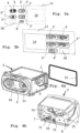
- the electrosurgical generator comprises a housing 10 having at least one output socket 3 (in the depicted exemplary embodiment a total of four output sockets 3', 3', 3") for connection of an electrosurgical instrument 9.
- a power supply cable 13 with a mains plug 12 is provided which is connectable to an electrical power source which may be an electricity grid, like AC mains in a building, or an off-grid source of electric energy, like a 12 Volt or 24 Volt battery in a vehicle or mobile hospital.
- a user interface 14 is provided comprising a display 15 and an input device like knobs 16 for inputs by the user.
- the display 15 shows information concerning the inputs made by the user and the status of the electrosurgical generator 1.
- the user interface 14 the user can issue directions and commands to a control unit 20 which controls operation of the electrosurgical generator 1 and its components, including frequency and voltage of the AC voltage emitted by the output socket 3 as well as modes of operation.
- Said electrosurgical instrument comprises a cable 93 with a high voltage plug 94 which is to be plugged-in into the output socket 3 in order to supply the high-frequency alternating voltage for operation of the electrosurgical instrument 9.
- Fig. 2 shows a schematic functional diagram of an internal circuitry 2 of the electrosurgical generator 1. It comprises a power supply unit 21 that is fed with electrical energy by the supply cable 13, the power supply unit 21 feeding a DC bus 22 connected to an inverter 23 configured for generating high-frequency alternating current in a high-voltage range of a few kilovolts. Operation of the inverter 23 is governed by the control unit 20 which in turn is connected with the user interface 14 such that the user can issue directions and commands for operation of the electrosurgical generator 1.
- the control unit 20 generates corresponding control signals and governs the relevant components of the internal circuitry 2 according to these instructions and commands. According to this, the inverter 23 generates high-frequency alternating voltage which is to be supplied to the electrosurgical instrument 19.
- the high-frequency high-voltage output emitted by the inverter 23 is routed via an output connection 24 to the output socket 3.
- the output connection 24 typically comprises two conductors, one for a neutral electrode NE and one other for an active electrode AE, which comprises a DC blocking capacitor 25 in its conductor.
- the electrosurgical instrument 9 with its cable 93 and attached plug 94 can be plugged into the output socket 3. Actual voltage and current of the high-frequency alternating voltage as being supplied to the output socket 3 are measured by a voltage/current sensor 28. Its measurement signals are fed back by a feedback unit 29 to the control unit 20 of the electrosurgical generator 1.
- the output socket 3 comprises a casing 4 having a plug socket 5 configured to receive the plug 94 of the electrosurgical instrument 9, the plug socket 5 being positioned at a frontal face of the casing 4 in order to be readily accessible.
- Attached to this connector 7 are the high-power high-frequency alternating voltage lines, namely the power delivered via the output connection 24 to the output socket 3, and other data and/or signal lines which are symbolized by a dashed line 26 for communication and data interchange with the output socket 3 and preferably also with the instrument 9 connected via its plug 94.
- electrosurgical instruments 9 of different kinds being differently configured, e.g. unipolar or bipolar, and having different plugs 94 to be attached into one of a variety of different output socket 3, 3', 3".
- the plugs 94 may be differently configured, in particular they may have one or two prongs 95 for the high-frequency alternating voltage, depending on whether it is a unipolar or bipolar electrosurgical instrument 9. Further, an additional prong 96 may be provided for data signals but data transmission may also be contactless.
- a front and a back view of a front plate 11 of the housing 10 are shown.
- the front plate 11 is configured with various examples of such different output sockets 3, 3', 3".
- the output sockets 3, 3', 3" all have the same size and share the same external contour, thereby enabling them to be placed in identical cutouts.
- an output socket 8 of a second group which is smaller and is configured for providing neutral earth potential.
- a spare cutout 18 is depicted in Fig. 3a, 3b by a dashed line. Accordingly, any of the output sockets can be placed into one of the cutouts without requiring any further modification. This facilitates equipping the electrosurgical generator 1 with different output sockets 3, 3', 3".
- the configuration of the output socket 3 with its conductor board 6 is shown in Fig. 4a, 4b and Fig. 5 .
- the conductor board 6 is inserted exchangeable into the casing 4.
- Alternative embodiments of the conductor board 6', 6" that may exchangeably be inserted into the casing 4 are shown in Fig. 6a, 6b .
- the casing 4 features a general box-like construction and is shown in partly cutaway perspective views in Fig. 4a, 4b .
- the plug socket 5 is positioned at the frontal face of the casing 4 .
- the plug socket 5 is configured to receive the plug 94 with its prongs 95 of the electrosurgical instrument 9.
- Various alternative embodiments of the plug sockets 5', 5", 5 can be seen in Fig. 1 and 3a .
- a light guide 44 is further provided at the front face and is framing the external perimeter of the plug socket 5. Accordingly, the plug socket 5 framed by the light guide 44 is illuminated, and further color-coded status signals can be conveyed to the user if the illumination is made in various colors.
- the rear face of the casing 4, as shown in Fig. 4b features a generally open construction. From this opening the conductor board 6 is to be inserted into the casing 4 and affixed therein. At the rear end of the conductor board 6 the connector 7 is provided configured for connecting the casing 4 with its conductor board 6 to the internal circuitry 2 of the electrosurgical generator 1. It conveys the high-frequency high voltage power as well as data and signal lines. To this end a separator 70 is provided which delimits two portions 71, 72 of the connector 7.
- the separator 70 may be a structural element or it may be a predefined spacing having a predefined minimum distance for proper spatial separation to high-voltage lines.
- the portion 71 is configured for accepting data and signal lines and connecting these to conductors of the conductor board 6, whereas the portion 72 is configured for connecting the high-power high-frequency alternating voltage as generated by the inverter 23 and conveyed to the output socket 3 by the output connection 24.
- the portion 72 may connect the high-power lines, in particular the output connection 24 of the inverter 23, likewise to conductors of the conductor board 6; but in a preferred alternative as depicted in Fig. 4b , this portion 72 of the connector 7 is connected via direct high-voltage wiring 74, 75 to the respective contacts of the plug socket 5 accepting the prongs 95 of the plug 94 of the electrosurgical instrument 9.
- the conductor board 6 with its components will be explained in more detail with reference to Fig. 5 . Further, the plug socket 5 with its surrounding light guide 44 is shown. At a rear side (lower portion in the figure) of the conductor board 6 the connector 7 is shown that is mounted directly on the conductor board 6. At a front side close to a lateral edge of the conductor board 6, a light emitting device 81 is mounted. The light-emitting device 81 is located at a unitary position 82 in front of an appendage 45 of the light guide 44, the appendage 45 functioning as an entrance for light emitted by the light emitting device 81.
- the light emitting device 81 features a plurality of LEDs having different colors, in particular red, green and yellow; however, a multi-color LED may also be used.
- a proper coupling of the light as emitted by the light-emitting device 81 into the light guide 44 can be achieved regardless of the actual configuration of the conductor board 6 and/or the light-emitting device 81, thereby facilitating usage of a different conductor board.
- the conductor board 6 is equipped with a contactless interface 64, in particular a RFID device. It may further be equipped with a proximity sensor 65 which is configured to detect whether or not a plug 94 is plugged into the plug socket 5. Further, the contactless interface 64 may be provided with a data interface 66. Two purposes can be realized by means of the proximity sensor 65 and/or the data interface 66: firstly, it can be detected whether or not an electrosurgical instrument 9 is plugged into the output socket 3, and secondly - if the electrosurgical instrument 9 is plugged in - it can be determined which kind or type of electrosurgical instrument 9 is connected.
- an internal memory 92 of the electrosurgical instrument 9 may be read out thereby providing additional data about the type, kind of the electrosurgical instrument 9 and/or of specifics about usage of the electrosurgical instrument 9. Further by means of said interface it may be possible to read certain modes of operation (“modes") from the internal memory 92 of the electrosurgical instrument 9 and to convey this information via the connector 7 to the control unit 20 of the electrosurgical generator 1 such that the electrosurgical generator 1 can be operated according to said mode.
- modes modes of operation
- driving electronic components 60 can be provided on the conductor board 6, and further a control electronic component 68 can be provided for controlling the various components of the conductor board 6 including the contactless interface 64.
- a supplemental data interface 69 may be provided on the conductor board 6 that is configured to communicate with certain devices on the electrosurgical instrument 9, like a hand switch 91 provided on the body of the electrosurgical instrument 9.
- the data interface 69 may also be configured to communicate with a data source of the electrosurgical instrument 9, for example the internal memory 92. Thereby activities of the user, like actuating the hand switch 91 can be detected and the information can be propagated via the connector 7 and the data line 26 to the control unit 20 of the electrosurgical generator.
- a modular identifying unit 67 is provided on the conductor board 6. It is configured to identify type of the output socket 3 and functionality of its conductor board 6. This modular identifying unit 67 communicates with the internal circuitry 2 of the electrosurgical generator 1, in particular its control unit 20. By virtue of this modular identifying unit 67, the control unit 20 can determine 9 which kind of output socket 3 are installed and which are their capabilities, and based thereon the control unit 20 can (self) configure the electrosurgical generator 1 and/or adjust operation of the electrosurgical generator 1.
- the modular identifying unit 67 may be configured as an passive or active unit, like having a resistor or R/C network, or being active, like being equipped with a microprocessor or (E)EPROM for more granular or complex identification.
- FIG. 6a and 6b Alternative embodiments of the conductor board 6' and 6" are shown in Fig. 6a and 6b . These are conductor boards having different functionality and which can be inserted into the same casing 4 to form a different output socket 3', 3", if required with a different plug socket 5', 5", without requiring any mechanical modifications, thereby maintaining the benefits and ease of mounting and connecting.
- Conductor board 6' is a simplified version having fewer components.
- the light-emitting device 81' is equipped with a single multicolor LED. However, as opposed to the embodiment shown in Fig. 5 the connector 7 features in its portion 72 two pairs of direct cabling connection 74, 75 to the plug socket 5.
- Conductor board 6" is another simplified version. Its light-emitting device 81" is equipped with two single color LEDs and therefore communicates a lesser number of different color-coded information. Owing to the light-emitting device 81', 81" being located at the unitary position 82 no adaption of the light guide 44 with its appendage 45 is necessary.
- either of the conductor boards 6', 6" can be placed in the same casing 4 using the same type of connector 7 for connection to the internal circuitry 2 of the electrosurgical generator. Providing a variety of output socket set 3, 3', 3" is thereby much facilitated.
- a first simple but effective variant is shown having a through hole 42 at the casing 4.
- Said through hole 42 runs from a rear side to a front side of the casing 4.
- An LED 81 I is provided at the rear end of the through hole 42 for lighting.
- a filter 49 is mounted at a front side of the through hole, thereby enabling coloring of the light emitted by the LED 81 I .
- the through hole 45 needs to be manufactured for an efficient and space saving mounting of the LED 81 I , and the filter 49 may be applied if a need for coloring is to be met but might be omitted in other cases for further simplification. Any driving electronics may be placed at will, thereby further reducing spatial requirements of this variant.
- Fig. 8a-c shows a second variant employing a light guide 44 which is placed in a notch 43 running along three sides of a frontal face 41 of the casing 4. Said three sides are the two lateral as well the top side of the frontal face 41, however other configurations are possible, too.
- the outer perimeter of the structure of the casing 4 provided with the notch 43 is affixed into a hole of the frontal plate 11 of the generator housing 10.
- an HF sealing 31 is provided (shown in Fig. 4a in a exploded view). It runs circumferentially around the perimeter of the casing 4 and will be located between the frontal plate 11 and said perimeter of the casing 4 in its mounted state.
- a translucent element 47 is to be placed in addition to the light guide 44.
- the light guide 44 sits at a bottom of the notch 43, and the translucent 47 covers the light guide. Thereby protection of the light guide 44 as well as a smooth diffusion of the light can be achieved. Owing to the light guide 44 and the translucent element 47 both being positioned in the notch 43, the perimeter of the casing 4 is not affected and therefore no additional or more complicated sealing will be required.
- the light guide 44 can be provided with an optional extension 46, as shown in Fig. 8c . Accordingly, the light-emitting device does not need to be placed at the casing 4 but rather can be located at a more remote place, somewhere in the housing 10 of the electrosurgical generator 1. This frees up valuable space at the casing 4 and allows for a rather free positioning of the light-emitting device within the housing.
- FIG. 9a-c An alternative approach for providing lighting according to a third variant is shown in Fig. 9a-c .
- the casing 4 is provided with a surrounding frame 80 carrying at least one light-emitting device, in particular an LED 81.
- the frame 80 thus forms the outer perimeter of the casing 4 and will be connected to the frontal plate 11, again optionally by using a sealing 31 between said frame 80 and the frontal plate 31.
- the frame 80 with the LED 81 is covered by a translucent front cover 47. Thereby, the additional functionalities "sealing” and "lighting" are integrated into the frame package.
- the LED 81 is offset towards the perimeter such as to be covered by the frontal plate 11 in the mounted state. No direct light from the LED 81 will be radiated into the eyes of the user, thereby reducing eye strain.
- a series of cutouts 40 is provided along a top edge of the frontal face 41 of the casing 4.
- the cutouts 40 are arranged in line with each other.
- a LED 81 is positioned, the LEDs 81 being arranged on a LED board 80 with a spacing matching the spacing of the cutouts 40.
- Light from the LEDs 81 thus can be directly radiated from the cutouts 40 to the frontal face 41 of the casing 4.
- the dashed ellipse symbolizes the radiation of the light.
- the LED board 80 is close to the cutouts 40 it is flush within the perimeter of the casing 4, thereby avoiding any need for additional sealing.
- a series of cutouts 40 is provided along a top edge of the frontal face 41, similar to the fourth variant.
- a light guide 44 will be used instead of LEDs in the cutouts.
- the light guide 44 is placed such as to radiate light through the openings for direct illumination of the frontal face 41, similar to the fourth variant.
- due to the flush mounted light guide no additional sealing will be required.
- no LED is required at the casing, rather the light-emitting device can be placed anywhere in the housing 10 of the generator, wherever is a convenient location.
- the light guide 44 is provided with an extension 46, as already explained.
- a planar light guide 44 VI is provided in the casing 4 and forming the frontal face in the region of the plug 5. Further, the planar light guide 44 VI is provided with a masking 48 having a masking hole 48' around the plug socket 5. The planar light guide 44 VI is thus positioned approximately perpendicular to the direction of inserting the plug of the electrosurgical instrument 9 into the plug socket. This allows for an efficient pinpointed lighting of the actual plug, thereby facilitating insertion of the plug of the electrosurgical instrument 9.
- a seventh variant as depicted in Fig. 12b contacting within the plug 5 is performed by means of a contact sleeve being contacted by a rear mounted contact ring 53.
- a socket through hole 51 is formed leading from the frontal face 41 all the way to a rear opening of the plug.
- a LED 81 is mounted in the rear opening of the socket through hole 51, being enabled to radiate light through said through hole 51 towards the frontal face 41.
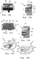
- the conductor board 6 is configured as an angled printed circuit board assembly 6*, comprising a horizontally extending conductor board 62 and a vertically extending conductor board 61.
- the connector 7 is mounted on a rear end of the horizontally extending conductor board 62 .
- the angled printed circuit board assembly 6* with its components will be explained in more detail with reference to Fig. 13a, b and Fig. 14a , b.
- the connector 7 is shown at a rear edge 628 of the horizontally extending conductor board 62 .
- the vertically arranged conductor board 61 is arranged.
- FIG. 13a A bottom view of the circuit board assembly 6* in a non-angled state is shown in Fig. 13a , and in Fig. 13b a perspective view of the assembly being transferred in its angled state is shown.
- the conductors 625 can be seen connecting the area where the connector 7 (symbolized by dashed lines) is to be mounted with the vertically extending conductor board 61 via a flexible inter-connector 65.
- Conductor board 61 is provided with electric components, like a plurality of light sources 612 and/or a proximity sensor 611 of an RFID type which is configured to detect whether or not a plug 94 is plugged into the plug socket 5.
- the horizontally extending conductor board 62 can be provided with electric components, like a contactless interface 622 which is configured to determine which kind or type of electrosurgical instrument 9 is plugged in and forwards corresponding data by the data lines of the connector 7 and the data line 26 to the control unit 20 of the electrosurgical generator 1.
- the conductor board 61 is provided with two clearance holes 60, 60' which are being shaped and dimensioned such as to allow for passage of a body 56 of each of the plug socket 5, 5'.
- the light sources 612 are arranged along the perimeter of the clearance holes 60, 60'.
- the horizontally extending conductor board 62 is attached to a lower edge 617 of the vertically extending conductor board 61; attaching to an upper edge 616 would also be possible.
- This provides for a flat orientation and a rather large surface of the horizontally extending conductor board 62, thereby facilitating positioning of even complex electrical circuits with many components.
- the horizontally extending conductor board 62' may also be attached to a lateral side of the vertically extending conductor board 61, in the depicted embodiment to the left lateral side 618. Thereby an alternative angled printed circuit assembly 6** can be formed.
- FIG. 15a , b A preferred embodiment of the angled printed circuit board assembly 6* being a rigid-flex printed circuit board having the flexible inter-connector formed as a unitary piece is shown in detail in Fig. 15a , b. These figures show the flexible inter-connector 65 in an original flat state in Fig. 15a and in an operative angled state are shown in Fig. 15b .
- the flexible inter-connector 65 is a unitary piece that features extensions arranged on one of the main surfaces of either conductor board 61, 62.
- the conductor board 61 is moved into a vertical position which requires no further action than just tilting this board 61 into the appropriate position as the flexible inter-connector 65 will follow as needed.
- FIG. 16a and b A perspective view and a cross-section of the casing 4 with the angled printed circuit conductor board assembly 6* in its assembled position are shown in Fig. 16a and b.
- Two socket plugs 5, 5' are shown which are positioned in the clearance holes 60, 60' having their body 56 placed in the large space behind the front face 41 of the casing 4.
- At the rear of the body 56 of either socket plugs 5, 5' having contact tabs 55 are shown which are configured to receive the direct wiring 74, 75 (as shown in Fig. 4b ) for supply of the high-frequency high voltage from the connector 7.
- a clamping device 54 which is configured as a nut. It is to be tightened such as to force the plug socket 5 into a defined position with respect to the front face 41.
- the vertically extending conductor board 61 is placed under the nut of the clamping device 54, thereby also affixing the conductor board 61 to the frontal face 41 and thereby increasing stability.
- an appendage 45 having an entry portion of the light guide 44 is shown. Due to the angled position of the vertically extending conductor board 61, the light source 612 mounted thereon is automatically positioned in front of said entry portion of the appendage 45 upon inserting and assembling of the angled printed circuit board assembly 6* into the casing 4. This allows for efficient manufacturing and assembly of the output socket 3.
- the other output sockets 3', 3" are likewise configured and assembled; they mainly differ in number and kind of the plug sockets 5, 5'.
- Final assembly can be achieved just by placing the output socket 3, 3' with its casing 4 into its position at the front face 11 of the housing 10 of the electrosurgical generator 1 and to connect the connector 7 to the internal circuitry 2 of the electrosurgical generator 1.
Landscapes
- Health & Medical Sciences (AREA)
- Engineering & Computer Science (AREA)
- Surgery (AREA)
- Life Sciences & Earth Sciences (AREA)
- Biomedical Technology (AREA)
- Molecular Biology (AREA)
- Nuclear Medicine, Radiotherapy & Molecular Imaging (AREA)
- Plasma & Fusion (AREA)
- Physics & Mathematics (AREA)
- Heart & Thoracic Surgery (AREA)
- Medical Informatics (AREA)
- Otolaryngology (AREA)
- Animal Behavior & Ethology (AREA)
- General Health & Medical Sciences (AREA)
- Public Health (AREA)
- Veterinary Medicine (AREA)
- Microelectronics & Electronic Packaging (AREA)
- Surgical Instruments (AREA)
Applications Claiming Priority (2)
| Application Number | Priority Date | Filing Date | Title |
|---|---|---|---|
| US202263411374P | 2022-09-29 | 2022-09-29 | |
| US202263411232P | 2022-09-29 | 2022-09-29 |
Publications (1)
| Publication Number | Publication Date |
|---|---|
| EP4344663A1 true EP4344663A1 (fr) | 2024-04-03 |
Family
ID=88207576
Family Applications (1)
| Application Number | Title | Priority Date | Filing Date |
|---|---|---|---|
| EP23200133.9A Pending EP4344663A1 (fr) | 2022-09-29 | 2023-09-27 | Générateur électrochirurgical avec douille de sortie modulaire pour instrument électrochirurgical |
Country Status (3)
| Country | Link |
|---|---|
| US (1) | US20240108395A1 (fr) |
| EP (1) | EP4344663A1 (fr) |
| JP (1) | JP2024050491A (fr) |
Citations (2)
| Publication number | Priority date | Publication date | Assignee | Title |
|---|---|---|---|---|
| US20150229083A1 (en) * | 2014-02-10 | 2015-08-13 | Erbe Elektromedizin Gmbh | Socket Insert For An Electrosurgical Device, Electrosurgical Device With A Socket Insert And Set With A Removal Tool |
| EP3758157A1 (fr) | 2019-06-27 | 2020-12-30 | Erbe Elektromedizin GmbH | Appareil pourvu d'interface de service et procédé d'entretien de l'appareil |
-
2023
- 2023-09-27 EP EP23200133.9A patent/EP4344663A1/fr active Pending
- 2023-09-27 US US18/373,907 patent/US20240108395A1/en active Pending
- 2023-09-27 JP JP2023164182A patent/JP2024050491A/ja active Pending
Patent Citations (3)
| Publication number | Priority date | Publication date | Assignee | Title |
|---|---|---|---|---|
| US20150229083A1 (en) * | 2014-02-10 | 2015-08-13 | Erbe Elektromedizin Gmbh | Socket Insert For An Electrosurgical Device, Electrosurgical Device With A Socket Insert And Set With A Removal Tool |
| EP3758157A1 (fr) | 2019-06-27 | 2020-12-30 | Erbe Elektromedizin GmbH | Appareil pourvu d'interface de service et procédé d'entretien de l'appareil |
| US20200412668A1 (en) * | 2019-06-27 | 2020-12-31 | Erbe Elektromedizin Gmbh | Apparatus with Service Interface and Method for Servicing the Apparatus |
Also Published As
| Publication number | Publication date |
|---|---|
| JP2024050491A (ja) | 2024-04-10 |
| US20240108395A1 (en) | 2024-04-04 |
Similar Documents
| Publication | Publication Date | Title |
|---|---|---|
| US9112321B2 (en) | Illuminated receptacle | |
| US6149288A (en) | Vehicle light assembly with detachable and replaceable circuit board having plug-in terminal connectors | |
| CN101960204B (zh) | 用于led插座的集成led驱动器 | |
| US20080205059A1 (en) | Lighting apparatus cable and lighting apparatus using the same | |
| US20070038024A1 (en) | Endoscope electric connection device | |
| EP2792026B1 (fr) | Connecteurs électriques destinés à être utilisés conjointement avec des cartes de circuit imprimé | |
| KR101744511B1 (ko) | 터미널블록을 위한 인디케이터 장치 | |
| CN112787171B (zh) | 底座连接器 | |
| CN112787148A (zh) | 用于工作表面的电力单元 | |
| US8680958B2 (en) | Housing for an electrically powered device | |
| ES2428721T3 (es) | Enchufe hembra eléctrico con tapa abatible | |
| EP4344663A1 (fr) | Générateur électrochirurgical avec douille de sortie modulaire pour instrument électrochirurgical | |
| US20030185003A1 (en) | Overhead lighting splitter | |
| KR20140100875A (ko) | 발광모듈, 직관형 램프 및 조명 장치 | |
| CN117770937A (zh) | 电外科发生器 | |
| US20190234602A1 (en) | Illumination module assembly | |
| US6164797A (en) | End mount ballast- socket bridge | |
| EP2448071A1 (fr) | Dispositif de connexion de télécommunication | |
| US6429593B1 (en) | Lighting device | |
| US20030139074A1 (en) | Electrical adapter | |
| DE102022125312B3 (de) | Elektrochirurgischer Generator mit Ausgangsbuchse für elektrochirurgisches Instrument | |
| KR200315021Y1 (ko) | 신호기용 2중 전원장치 | |
| CN219014231U (zh) | 一种灯具 | |
| JPH10305009A (ja) | 医用電気機器 | |
| CN212187476U (zh) | 射频治疗仪的电极设备 |
Legal Events
| Date | Code | Title | Description |
|---|---|---|---|
| PUAI | Public reference made under article 153(3) epc to a published international application that has entered the european phase |
Free format text: ORIGINAL CODE: 0009012 |
|
| STAA | Information on the status of an ep patent application or granted ep patent |
Free format text: STATUS: THE APPLICATION HAS BEEN PUBLISHED |
|
| AK | Designated contracting states |
Kind code of ref document: A1 Designated state(s): AL AT BE BG CH CY CZ DE DK EE ES FI FR GB GR HR HU IE IS IT LI LT LU LV MC ME MK MT NL NO PL PT RO RS SE SI SK SM TR |