US6164797A - End mount ballast- socket bridge - Google Patents
End mount ballast- socket bridge Download PDFInfo
- Publication number
- US6164797A US6164797A US09/135,156 US13515698A US6164797A US 6164797 A US6164797 A US 6164797A US 13515698 A US13515698 A US 13515698A US 6164797 A US6164797 A US 6164797A
- Authority
- US
- United States
- Prior art keywords
- ballast
- lampholders
- lighting fixture
- fluorescent lighting
- circuit board
- Prior art date
- Legal status (The legal status is an assumption and is not a legal conclusion. Google has not performed a legal analysis and makes no representation as to the accuracy of the status listed.)
- Expired - Lifetime
Links
Images


Classifications
-
- H—ELECTRICITY
- H01—ELECTRIC ELEMENTS
- H01R—ELECTRICALLY-CONDUCTIVE CONNECTIONS; STRUCTURAL ASSOCIATIONS OF A PLURALITY OF MUTUALLY-INSULATED ELECTRICAL CONNECTING ELEMENTS; COUPLING DEVICES; CURRENT COLLECTORS
- H01R33/00—Coupling devices specially adapted for supporting apparatus and having one part acting as a holder providing support and electrical connection via a counterpart which is structurally associated with the apparatus, e.g. lamp holders; Separate parts thereof
- H01R33/74—Devices having four or more poles, e.g. holders for compact fluorescent lamps
- H01R33/76—Holders with sockets, clips, or analogous contacts adapted for axially-sliding engagement with parallely-arranged pins, blades, or analogous contacts on counterpart, e.g. electronic tube socket
- H01R33/7607—Holders with sockets, clips, or analogous contacts adapted for axially-sliding engagement with parallely-arranged pins, blades, or analogous contacts on counterpart, e.g. electronic tube socket the parallel terminal pins having a circular disposition
- H01R33/7635—Holders with sockets, clips, or analogous contacts adapted for axially-sliding engagement with parallely-arranged pins, blades, or analogous contacts on counterpart, e.g. electronic tube socket the parallel terminal pins having a circular disposition the terminals being collectively connected, e.g. to a PCB
-
- F—MECHANICAL ENGINEERING; LIGHTING; HEATING; WEAPONS; BLASTING
- F21—LIGHTING
- F21V—FUNCTIONAL FEATURES OR DETAILS OF LIGHTING DEVICES OR SYSTEMS THEREOF; STRUCTURAL COMBINATIONS OF LIGHTING DEVICES WITH OTHER ARTICLES, NOT OTHERWISE PROVIDED FOR
- F21V23/00—Arrangement of electric circuit elements in or on lighting devices
- F21V23/003—Arrangement of electric circuit elements in or on lighting devices the elements being electronics drivers or controllers for operating the light source, e.g. for a LED array
- F21V23/004—Arrangement of electric circuit elements in or on lighting devices the elements being electronics drivers or controllers for operating the light source, e.g. for a LED array arranged on a substrate, e.g. a printed circuit board
- F21V23/006—Arrangement of electric circuit elements in or on lighting devices the elements being electronics drivers or controllers for operating the light source, e.g. for a LED array arranged on a substrate, e.g. a printed circuit board the substrate being distinct from the light source holder
-
- F—MECHANICAL ENGINEERING; LIGHTING; HEATING; WEAPONS; BLASTING
- F21—LIGHTING
- F21V—FUNCTIONAL FEATURES OR DETAILS OF LIGHTING DEVICES OR SYSTEMS THEREOF; STRUCTURAL COMBINATIONS OF LIGHTING DEVICES WITH OTHER ARTICLES, NOT OTHERWISE PROVIDED FOR
- F21V23/00—Arrangement of electric circuit elements in or on lighting devices
- F21V23/02—Arrangement of electric circuit elements in or on lighting devices the elements being transformers, impedances or power supply units, e.g. a transformer with a rectifier
-
- H—ELECTRICITY
- H01—ELECTRIC ELEMENTS
- H01R—ELECTRICALLY-CONDUCTIVE CONNECTIONS; STRUCTURAL ASSOCIATIONS OF A PLURALITY OF MUTUALLY-INSULATED ELECTRICAL CONNECTING ELEMENTS; COUPLING DEVICES; CURRENT COLLECTORS
- H01R33/00—Coupling devices specially adapted for supporting apparatus and having one part acting as a holder providing support and electrical connection via a counterpart which is structurally associated with the apparatus, e.g. lamp holders; Separate parts thereof
- H01R33/05—Two-pole devices
- H01R33/06—Two-pole devices with two current-carrying pins, blades or analogous contacts, having their axes parallel to each other
- H01R33/08—Two-pole devices with two current-carrying pins, blades or analogous contacts, having their axes parallel to each other for supporting tubular fluorescent lamp
- H01R33/089—Two-pole devices with two current-carrying pins, blades or analogous contacts, having their axes parallel to each other for supporting tubular fluorescent lamp integral with starter holding structure
-
- H—ELECTRICITY
- H05—ELECTRIC TECHNIQUES NOT OTHERWISE PROVIDED FOR
- H05K—PRINTED CIRCUITS; CASINGS OR CONSTRUCTIONAL DETAILS OF ELECTRIC APPARATUS; MANUFACTURE OF ASSEMBLAGES OF ELECTRICAL COMPONENTS
- H05K1/00—Printed circuits
- H05K1/18—Printed circuits structurally associated with non-printed electric components
Definitions
- the present invention relates generally to fluorescent lighting fixtures, and more particularly to an improved manner of connecting the internal ballast in a fluorescent lighting fixture to the fluorescent lamp holders.
- the use of fluorescent lighting is widespread in both residential and commercial establishments, primarily because of its low operating costs and the pleasant light it provides.
- the conventional fluorescent lighting fixture includes a generally rectangular or square housing that includes one or more pairs of lamp holders in which a corresponding number of fluorescent lamps are mounted.
- An electrical ballast also mounted in the housing controls the amount of current that is supplied to the fluorescent lamps and provides the proper operating voltage to start the lamps.
- the electromagnetic ballast includes a transformer and usually a capacitor
- the electronic ballast includes a plurality of electrical components mounted on a printed circuit board to establish the requisite circuitry to rectify the incoming 60 cycle a.c. voltage, and then to create a high-frequency voltage, typically above 20 kHz, to operate the fluorescent lamps.
- the ballast In a conventional fluorescent lighting fixture, the ballast is enclosed in a ballast enclosure that runs the length of the fixture.
- a plurality of wires extend from the ballast to the lamp holders to supply the operating voltage to the lamps.
- four long lead wires extend from the ballast to make electrical connection to the lamp holders. The need to run these wires and to plug them into the lampholders adds materially to the time and the cost of assembling the fixture, which, in turn, adds to the cost of the fixture to the consumers.
- the fluorescent lighting fixture of the invention employs an electronic ballast, the elements of which are mounted on a printed circuit board.
- the output connectors on the board are connected to the lampholders through output pins of the printed circuit board which are mounted directly into the lampholders.
- the present invention relates to a fluorescent lighting fixture substantially as defined in the appended claims, as considered with the following detailed specification and the accompanying drawings, in which
- FIG. 1 is a plan view of a conventional fluorescent lighting fixture
- FIG. 2 is an elevation of the fluorescent lighting fixture of FIG. 1;
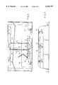
- FIG. 3 is a plan view of a fluorescent lighting fixture in accordance with a first embodiment of the invention.
- FIG. 4 is an elevation of the fixture of FIG. 3;
- FIG. 5 is a plan view of a fluorescent lighting fixture in accordance with a second embodiment of the invention.
- FIG. 6 is an elevation of the fixture of FIG. 5.
- a conventional fluorescent lighting fixture as illustrated in FIGS. 1 and 2, includes a rectangular fixture housing 10, in which are mounted a plurality, here three, of pairs of axially aligned spaced lamp holders 12, 14 and 16 each of which receives the opposite ends of a conventional fluorescent lamp (not shown).
- the opposing lampholders in each pair are respectively mounted on a pair of socket bridge covers 18, 20.
- ballast 24 Electrical operating voltage and current are supplied to the fluorescent lamps by means of a conventional ballast 24 mounted to the fixture housing by a mounting bracket 26.
- the ballast 24 receives a supply voltage via feed wires 28.
- Ballast 24, which may be, as is conventional, in the form of electronic components mounted on a printed circuit board (not shown in FIG. 1) produces the requisite high-voltage supply for the fluorescent lamps on four wires 30, 32, 34, 36. Wires 30, 36 are respectively connected to the lampholders 12, wire 32 is connected to the lampholders 14, and wire 34 is connected to the lampholders 16.
- a jumper wire 38 is run between the lampholders 12 and 14, and another jumper wire 42 is run between the lampholders 14 and 16.
- ballast 24 is enclosed within a ballast wireway cover 40, which extends across substantially the entire length of the fixture.
- the circuit board or ballast 24 in the conventional fixture is typically covered with an enclosure to limit the radiation of radio-frequency interference.
- the fluorescent lighting fixture of the present invention reduces the number of internal wires required to operate the fixture, and more specifically the number of such internal wires that are run between the ballast and the lamp holders.
- the embodiment of the invention illustrated in FIGS. 3 and 4 the number of internal wires needed to operate a three-lamp fixture is reduced from three wires, as in the prior art three-lamp fixture illustrated in FIGS. 1 and 2, to a single wire.
- the ballast is in the form of a printed circuit board 50 on which are mounted a plurality of electronic components 52 that perform the required electrical operations on the input supply a.c. voltage to create at its output the required operating voltage and current for the lamps.
- the printed circuit board 50 receives, as in the conventional fixture, the supply voltage via feed wires 54 at a input contact 55.
- the printed circuit board includes pairs of mounting or wiring output pins 56, 58 and 60 that extend from the lower end of board 50. Output pins 56, 58 and 60 are directly mounted and connected to the lower lampholder in each lampholder pairs 12, 14 and 16, respectively, as seen best in FIG. 3, to supply the operating voltage and wires to the lampholders.
- a single wire 61 extends from an output pad 62 on printed circuit board 50 to one of the upper lampholders 12, 14 and 16, from which jumper wires 62 and 64 are respectively run for connection to the other upper lampholders.
- wire 61 is shown in FIG. 3 extending to upper lampholder 14.
- the other connections from the ballast to the lampholders are made via the output pins 56, 58 and 60 on the printed circuit board 50, which are directly mounted in and directly connected to the lampholders.
- the single wire 61 may be run through a rib 22 running the length of the housing. If desired a wiring cover 68 in the form of strips of insulating tape, or other material, may be placed over the rib 22.
- ballast 50 is enclosed in an enlarged socket bridge 66.
- the enlarged socket bridge 66 combined with the fixture housing, form an enclosure that captures the radio-frequency interference of the ballast. This eliminates the need for a separate enclosure that is typically provided by the ballast manufacturer.
- FIGS. 5 an 6 The embodiment of the invention illustrated in FIGS. 5 an 6 is intended for use with a pair of U-shaped fluorescent lamp (not shown), which extend respectively between two pairs of lampholders 70 and 72.
- a printed circuit board 74 is similar to that used in the embodiment of FIGS. 3 and 4, except that it includes four pairs of lampholder wiring pins 76, 78, 80 and 82, which are respectively mounted directly in and connected to the lamp holders 70 and 72, as shown in FIG. 5. It will be noted that in this embodiment not even a single wire is run between the printed circuit board and any lampholder or between lampholders. Rather, in this embodiment of the invention, all connections to the lampholders are made by the direct connection of the ballast outputs of the printed circuit board to the lampholders. And, as in the embodiment of FIGS. 3 and 4, in the embodiment of FIGS. 5 and 6, only a single enlarged socket bridge 66 is needed to enclose the ballast.
- the present invention provides a fluorescent lighting fixture utilizing an electronic ballast in which the need to run internal wires from the ballast to the lampholders is minimized, and even, as in one embodiment, completely eliminated.
- the present invention also does away with the need for a ballast case while reducing the creation of undesired radio-frequency interference.
- the fluorescent lighting fixture of the invention is thus less costly to assemble both in components and labor, and lends itself to the automatic insertion and mounting of the ballast and lampholder in the fixture housing.
Landscapes
- Engineering & Computer Science (AREA)
- General Engineering & Computer Science (AREA)
- Microelectronics & Electronic Packaging (AREA)
- Power Engineering (AREA)
- Arrangement Of Elements, Cooling, Sealing, Or The Like Of Lighting Devices (AREA)
Abstract
Description
Claims (5)
Priority Applications (2)
| Application Number | Priority Date | Filing Date | Title |
|---|---|---|---|
| US09/135,156 US6164797A (en) | 1998-08-17 | 1998-08-17 | End mount ballast- socket bridge |
| CA002277527A CA2277527C (en) | 1998-08-17 | 1999-07-13 | End mount ballast/socket bridge |
Applications Claiming Priority (1)
| Application Number | Priority Date | Filing Date | Title |
|---|---|---|---|
| US09/135,156 US6164797A (en) | 1998-08-17 | 1998-08-17 | End mount ballast- socket bridge |
Publications (1)
| Publication Number | Publication Date |
|---|---|
| US6164797A true US6164797A (en) | 2000-12-26 |
Family
ID=22466799
Family Applications (1)
| Application Number | Title | Priority Date | Filing Date |
|---|---|---|---|
| US09/135,156 Expired - Lifetime US6164797A (en) | 1998-08-17 | 1998-08-17 | End mount ballast- socket bridge |
Country Status (2)
| Country | Link |
|---|---|
| US (1) | US6164797A (en) |
| CA (1) | CA2277527C (en) |
Cited By (7)
| Publication number | Priority date | Publication date | Assignee | Title |
|---|---|---|---|---|
| US20050012463A1 (en) * | 2003-07-16 | 2005-01-20 | Shanghai Viva Eco Electronics & Technology Co., Ltd. | One-to-many compact fluorescent lamp holder structure |
| US20070164681A1 (en) * | 2006-01-05 | 2007-07-19 | Canlyte Inc. | Sensing Light Fixture Device |
| USRE40619E1 (en) | 2002-12-05 | 2009-01-06 | Genlyte Thomas Group Llc | Efficient fluorescent lighting system |
| EP2020568A1 (en) * | 2007-08-02 | 2009-02-04 | E.R.C. Elettro Radio Costruzioni S.p.A. | Lighting body with quick-connect system |
| US20090034263A1 (en) * | 2007-08-03 | 2009-02-05 | Alumalight, L.L.C. | Fluorescent light fixture |
| US7490960B1 (en) | 2006-12-15 | 2009-02-17 | Genlyte Thomas Group Llc | Add-on sensor module for lighting system |
| US8113684B2 (en) * | 2008-07-15 | 2012-02-14 | Leviton Manufacturing Co., Inc. | Fluorescent lamp support |
Citations (2)
| Publication number | Priority date | Publication date | Assignee | Title |
|---|---|---|---|---|
| US4969070A (en) * | 1989-07-17 | 1990-11-06 | Valmont Industries, Inc. | Fluorescent fixture housing |
| US5720546A (en) * | 1994-09-20 | 1998-02-24 | The Whitaker Corp | Integrated ballast and lamp connector |
-
1998
- 1998-08-17 US US09/135,156 patent/US6164797A/en not_active Expired - Lifetime
-
1999
- 1999-07-13 CA CA002277527A patent/CA2277527C/en not_active Expired - Fee Related
Patent Citations (2)
| Publication number | Priority date | Publication date | Assignee | Title |
|---|---|---|---|---|
| US4969070A (en) * | 1989-07-17 | 1990-11-06 | Valmont Industries, Inc. | Fluorescent fixture housing |
| US5720546A (en) * | 1994-09-20 | 1998-02-24 | The Whitaker Corp | Integrated ballast and lamp connector |
Cited By (9)
| Publication number | Priority date | Publication date | Assignee | Title |
|---|---|---|---|---|
| USRE40619E1 (en) | 2002-12-05 | 2009-01-06 | Genlyte Thomas Group Llc | Efficient fluorescent lighting system |
| US20050012463A1 (en) * | 2003-07-16 | 2005-01-20 | Shanghai Viva Eco Electronics & Technology Co., Ltd. | One-to-many compact fluorescent lamp holder structure |
| US20070164681A1 (en) * | 2006-01-05 | 2007-07-19 | Canlyte Inc. | Sensing Light Fixture Device |
| US7585087B2 (en) | 2006-01-05 | 2009-09-08 | Canlyte Inc. | Sensing light fixture device |
| US7490960B1 (en) | 2006-12-15 | 2009-02-17 | Genlyte Thomas Group Llc | Add-on sensor module for lighting system |
| EP2020568A1 (en) * | 2007-08-02 | 2009-02-04 | E.R.C. Elettro Radio Costruzioni S.p.A. | Lighting body with quick-connect system |
| US20090034263A1 (en) * | 2007-08-03 | 2009-02-05 | Alumalight, L.L.C. | Fluorescent light fixture |
| US7604379B2 (en) | 2007-08-03 | 2009-10-20 | Alumalight, L.L.C. | Fluorescent light fixture |
| US8113684B2 (en) * | 2008-07-15 | 2012-02-14 | Leviton Manufacturing Co., Inc. | Fluorescent lamp support |
Also Published As
| Publication number | Publication date |
|---|---|
| CA2277527C (en) | 2007-05-29 |
| CA2277527A1 (en) | 2000-02-17 |
Similar Documents
| Publication | Publication Date | Title |
|---|---|---|
| US6217190B1 (en) | Lighting assembly for multiple fluorescent lamps | |
| KR0129581Y1 (en) | Compact fluorescent lamp of ballast structure | |
| US5720546A (en) | Integrated ballast and lamp connector | |
| CA1241991A (en) | Compact electric discharge lamp to standard indandescent socket adaptor | |
| US6814462B1 (en) | Under-cabinet lighting system | |
| US6100638A (en) | Kit for converting lighting units employing fluorescent lamps from inductive operation to electronic operation | |
| US3949211A (en) | Luminaire having ballast circuitry in photocontrol housing | |
| US5569981A (en) | Ballast device for compact fluorescent lamp | |
| US6492773B2 (en) | Self-ballasted fluorescent lamp | |
| US6164797A (en) | End mount ballast- socket bridge | |
| EP1142453B1 (en) | Kit for converting lighting units employing fluorescent lamps from inductive operation to electronic operation | |
| US7445353B2 (en) | Distributed lighting system | |
| US5202607A (en) | Adapter for fluorescent lamps | |
| US6048220A (en) | Lampholder connector for multiple fluorescent lamps | |
| US4969070A (en) | Fluorescent fixture housing | |
| JPH07211128A (en) | Luminaire | |
| MXPA99007552A (en) | Balastra bridge / receptacle mounted in extr | |
| US6099336A (en) | Cold cathode lamp lampholder with mains switching | |
| CA2280205C (en) | Multi-lamp assembly for miniature lighting strips | |
| JPS6129082B2 (en) | ||
| US6322381B1 (en) | Cold cathode lamp lampholder with mains switching | |
| JP2004146321A (en) | Fluorescent tube lighting fixture | |
| KR200285824Y1 (en) | Ballast stabilizer for an apparatus of fluorescent lamp | |
| KR200306815Y1 (en) | The ballast for a fluorescent lamp a utensil | |
| CN118517664A (en) | Modular drive unit and luminaire |
Legal Events
| Date | Code | Title | Description |
|---|---|---|---|
| AS | Assignment |
Owner name: LIGHTOLIER DIVISION OF THE GENLYTE GROUP INC., MAS Free format text: ASSIGNMENT OF ASSIGNORS INTEREST;ASSIGNORS:CRANE, ROY B.;METCALF, PAUL T.;FABBRI, WILLIAM C.;REEL/FRAME:009403/0945 Effective date: 19980810 |
|
| AS | Assignment |
Owner name: GENLYTE THOMAS GROUP LLC, A DELAWARE LIMITED LIABI Free format text: ASSIGNMENT OF ASSIGNORS INTEREST;ASSIGNOR:LIGHTOLIER DIVISION OF THE GENLYTE GROUP INC., A DELAWARE CORPORATION;REEL/FRAME:010687/0971 Effective date: 20000214 |
|
| STCF | Information on status: patent grant |
Free format text: PATENTED CASE |
|
| FPAY | Fee payment |
Year of fee payment: 4 |
|
| FPAY | Fee payment |
Year of fee payment: 8 |
|
| FPAY | Fee payment |
Year of fee payment: 12 |
|
| AS | Assignment |
Owner name: PHILIPS LIGHTING NORTH AMERICA CORPORATION, NEW JE Free format text: ASSIGNMENT OF ASSIGNORS INTEREST;ASSIGNOR:GENLYTE THOMAS GROUP LLC;REEL/FRAME:041085/0851 Effective date: 20160810 |