【0001】
【発明の属する技術分野】
本発明は蛍光灯ランプを使用する1灯2連結形照明器具に関する。
【0002】
【従来の技術】
従来の1灯2連結形蛍光灯照明器具は図3に示すように、2灯用点灯装置及び電源端子台を内蔵した器具本体と反射板とランプソケットと蛍光ランプからなる1灯用照明器具と、点灯装置を内蔵しない器具本休と反射板とランプソケットと蛍光ランプからなる1灯用照明器具を隣接するように設置し、両器具間は接続コネクタにより電気的に接続される。
このような器具の場合、電撃防止や雑音電力及び雑音端子電圧の低減のため、両器具間の接地を取る必要があり、従来では図4〜図5に示すように接続コネクタの1線を接地線とし、その両端は両器具の本体に固定する方法としていた。
【0003】
【発明が解決しようとする課題】
前記照明器具は、両照明器具間の接地を取るため、接続コネクタの1線を接地線とするため接続コネクタの極数を増やす必要が有り、また、接地線の両端は両器具本体に丸形端子、ネジ、ナットで固定する必要が有るため作業工数増によるコスト高の問題があつた。
本発明の目的は、電撃防止による安全性の確保及び雑音電力及び雑音端子・電圧の低減による信頼性の向上を図り、低コストの1灯2連結形照明器具を提供することにある。
【0004】
【課題を解決するための手段】
上記目的を達成するため、両器具本体を導電性金具で係合させることにより、接地を取るようにした。これにより、接続コネクタ極数の低減及び接地線固定作業工数の低減により、低コストの1灯2連結形照明器具を提供できる。
【0005】
【発明の実施の形態】
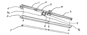
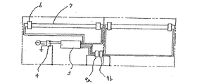
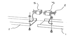
本発明の実施形態を図面で説明する。図1〜図2は、1灯2連結形照明器具の−実施例を示し、2灯用点灯装置3及び電源端子台4を内蔵した器具本体1と反射板5とランプソケット6と蛍光ランプ7からなる1灯用照明器具と、点灯装置を内蔵しない器具本体2と反射板5とランプソケット6と蛍光ランプ7からなる1灯用照明器具を隣接するように設置している。
両器具間はランプ線8が接続された4極の接続コネクタ9A、9Bで接続され2灯用点灯回路が構成される。接地用電線が接続可能な電源端子台4は、器具本体1に取付けることにより器具本体1と導適する接地構造となっている。点灯装置3を内蔵した器具本体1と点灯装置3を内蔵しない器具本体2導電性金具10により係合接続することで電気的に接続され 両器具共接地が可能となる。
このため、万一の電路の地絡による感電を防止することができるため安全性が確保でき、また点灯装置から発生する雑宵電力及び雑音端子電圧のレベルを低減させることができるため信頼性の向上が図られ、さらに接続コネクタの極数・接地線・固定ネジ等の低減及び作業工数低減によるコストダウンを図ることができる。
【0006】
【発明の効果】
本発明によれば,電撃防止による安全性の確保及び膝雑音電力及び雑音端子電圧の低減による信頼性の向上を図り、低コストの1灯2連結形照明器具を提供できる。
【図面の簡単な説明】
【図1】本発明器具の斜視図である。
【図2】その部分斜視図である。
【図3】従来器具を示す断面図である。
【図4】その結線図である。
【図5】同従来器具の部分断面図である。
【符号の説明】
1...点灯装置内蔵器具本体,2...点灯装置無し器具本体,3...2灯用点灯装置、4...電源端子台,5...反射板,6...ランプソケット,7...蛍光ランプ,8...ランプ線、9 A、9 B...接続コネクタ,10...導電性金具[0001]
TECHNICAL FIELD OF THE INVENTION
TECHNICAL FIELD The present invention relates to a one-light / two-link lighting device using a fluorescent lamp.
[0002]
[Prior art]
As shown in FIG. 3, a conventional one-lamp, two-link fluorescent lamp illuminating device includes a two-lamp lighting device, a device body having a built-in power supply terminal block, a reflector, a lamp socket, and a fluorescent lamp. A lighting fixture for lighting without a built-in lighting device, a reflector, a lamp socket, and a fluorescent lamp are installed so as to be adjacent to each other, and the two lighting fixtures are electrically connected by a connection connector.
In the case of such a device, it is necessary to ground the two devices in order to prevent electric shock and reduce noise power and noise terminal voltage. Conventionally, as shown in FIGS. A wire was used, and both ends were fixed to the main body of both devices.
[0003]
[Problems to be solved by the invention]
The lighting equipment needs to increase the number of poles of the connection connector in order to make one wire of the connection connector a ground wire in order to establish grounding between the two lighting equipments. Since it is necessary to fix with terminals, screws and nuts, there is a problem of high cost due to an increase in the number of work steps.
SUMMARY OF THE INVENTION An object of the present invention is to provide a low-cost, one-lamp, two-connection lighting fixture that ensures safety by preventing electric shock and improves reliability by reducing noise power and noise terminals and voltages.
[0004]
[Means for Solving the Problems]
In order to achieve the above object, grounding is performed by engaging both instrument bodies with a conductive metal fitting. Accordingly, a low-cost one-light / two-connection lighting fixture can be provided by reducing the number of connection connector poles and the number of steps for fixing the ground wire.
[0005]
BEST MODE FOR CARRYING OUT THE INVENTION
An embodiment of the present invention will be described with reference to the drawings. FIGS. 1 and 2 show an embodiment of a one-lamp, two-link type luminaire, in which a two-lamp lighting device 3 and a power supply terminal block 4 are incorporated in a luminaire body 1, a reflector 5, a lamp socket 6, and a fluorescent lamp 7. And a single-lamp lighting device including a lighting device, which does not include a lighting device, a reflector plate 5, a lamp socket 6, and a fluorescent lamp 7.
The two appliances are connected by four-pole connection connectors 9A and 9B to which a lamp wire 8 is connected to form a two-lamp lighting circuit. The power supply terminal block 4 to which the grounding wire can be connected has a grounding structure that is adapted to be connected to the instrument body 1 by being attached to the instrument body 1. The fixture main body 1 with the lighting device 3 incorporated therein and the fixture main body 2 without the lighting device 3 engaged and connected by the conductive metal fitting 10 are electrically connected to each other, and both appliances can be grounded.
For this reason, it is possible to prevent an electric shock due to a ground fault in the electric circuit, so that safety can be ensured. Also, since the level of noise power and noise terminal voltage generated from the lighting device can be reduced, reliability can be reduced. It is possible to reduce the number of poles, ground wires, fixing screws, and the like of the connector, and to reduce costs by reducing the number of work steps.
[0006]
【The invention's effect】
ADVANTAGE OF THE INVENTION According to this invention, the safety is ensured by preventing electric shock, and the reliability is improved by reducing the knee noise power and the noise terminal voltage.
[Brief description of the drawings]
FIG. 1 is a perspective view of the device of the present invention.
FIG. 2 is a partial perspective view thereof.
FIG. 3 is a sectional view showing a conventional device.
FIG. 4 is a connection diagram thereof.
FIG. 5 is a partial sectional view of the conventional device.
[Explanation of symbols]
1. . . 1. Lighting device built-in fixture body; . . 2. Instrument body without lighting device, . . 3. Two-light lighting device; . . Power supply terminal block, 5. . . Reflector, 6; . . Lamp socket, 7. . . Fluorescent lamp, 8. . . Lamp wire, 9A, 9B. . . Connector, 10. . . Conductive fitting