EP4343082A1 - Unmanned aerial vehicle base station and unmanned aerial vehicle system - Google Patents
Unmanned aerial vehicle base station and unmanned aerial vehicle system Download PDFInfo
- Publication number
- EP4343082A1 EP4343082A1 EP22930267.4A EP22930267A EP4343082A1 EP 4343082 A1 EP4343082 A1 EP 4343082A1 EP 22930267 A EP22930267 A EP 22930267A EP 4343082 A1 EP4343082 A1 EP 4343082A1
- Authority
- EP
- European Patent Office
- Prior art keywords
- base station
- uav
- protective cover
- blades
- closing mechanism
- Prior art date
- Legal status (The legal status is an assumption and is not a legal conclusion. Google has not performed a legal analysis and makes no representation as to the accuracy of the status listed.)
- Granted
Links
Images



Classifications
-
- B—PERFORMING OPERATIONS; TRANSPORTING
- B64—AIRCRAFT; AVIATION; COSMONAUTICS
- B64U—UNMANNED AERIAL VEHICLES [UAV]; EQUIPMENT THEREFOR
- B64U70/00—Launching, take-off or landing arrangements
- B64U70/90—Launching from or landing on platforms
- B64U70/92—Portable platforms
-
- B—PERFORMING OPERATIONS; TRANSPORTING
- B64—AIRCRAFT; AVIATION; COSMONAUTICS
- B64U—UNMANNED AERIAL VEHICLES [UAV]; EQUIPMENT THEREFOR
- B64U80/00—Transport or storage specially adapted for UAVs
- B64U80/70—Transport or storage specially adapted for UAVs in containers
Definitions
- Some embodiments of the present disclosure relate to the technical field of unmanned aerial vehicle (UAV), and in particular, to an unmanned aerial vehicle base station and an unmanned aerial vehicle system.
- UAV unmanned aerial vehicle
- UAVs have been widely used in many fields. Due to the limitation of the battery life of UAVs, UAVs cannot stay in the air for a long time to perform tasks. Therefore, a kind of UAV base station is usually designed on the ground. The main functions of the UAV base station can be used to charge the UAV, increase the UAV range, etc. In addition, the UAV base station can communicate with the UAV and can be used to control the takeoff and landing of the UAV.
- Embodiments of the present disclosure provide an unmanned aerial vehicle base station and an unmanned aerial vehicle system that can realize product miniaturization and reduce product cost and footprint.
- a UAV base station comprising a base body, a landing pad provided on the base body, and a base station opening and closing mechanism movably provided on the base body.
- the base station opening and closing mechanism comprises an open state and a closed state, wherein when the base station opening and closing mechanism is in the open state, a UAV can land on the landing pad; when the base station opening and closing mechanism is in the closed state, an accommodating space for accommodating the UAV is formed between the base station opening and closing mechanism and the landing pad, and the UAV comprises foldable blades, wherein when the UAV lands on the landing pad, the blades extending at least partially out of the accommodating space, the base station opening and closing mechanism being actuatable to fold the blades within the accommodating space after the UAV has landed on the landing pad, so as to hold the UAV within the accommodating space.
- a UAV system comprises a UAV and a UAV base station as described above.
- the UAV base station 100 includes a base body 10, a landing pad 20 disposed on the base body 10, and a base station opening and closing mechanism 30 movably disposed on the base body 10.
- the base station opening and closing mechanism 30 includes an open state and a closed state. As shown in Figs. 1 and 2 , when the base station opening and closing mechanism 30 is in the open state, the landing pad 20 is fully exposed and the UAV 200 may land on the landing pad 20. As shown in Figs. 3 through 5 , when the base station opening and closing mechanism 30 is in the closed state, an accommodating space 50 that can be used to hold the UAV 200 is formed between the base station opening and closing mechanism 30 and the landing pad 20, and the base station opening and closing mechanism 30 covers the landing pad 20 completely, and the landing pad 20 is fully contained within the accommodating space 50.
- the UAV 200 includes foldable blades 204. and, when the UAV 200 lands on the landing pad 20, the blades of the UAV 200 at least partially protrude outside of the accommodating space 50. In some embodiments, after the UAV 200 lands on the landing pad 20, the base station opening and closing mechanism 30 of an embodiment of the present disclosure may actuate the blades 204 to fold within the accommodating space 50 so that the UAV 200 is housed within the accommodating space 50.
- the UAV base station 100 of the embodiment of the present disclosure can automatically drive the base station opening and closing mechanism 30 to fold the blades 204 in the accommodating space 50 during the process of closing the base station opening and closing mechanism 30 after the UAV 200 lands on the landing pad 20, thereby holding the UAV 200 as a whole in the accommodating space 50.
- the area enclosed by the boundary of the accommodating space 50 formed between the base station opening and closing mechanism 30 and the landing pad 20 during the closed state of the base station opening and closing mechanism 30 can be greatly reduced relative to the projected area of the entire envelope of the UAV 200 as it is in the flight state.
- the area enclosed by the boundary of the accommodating space 50 as described herein refers to the area formed by the projection of the accommodating space 50 on a plane in which the landing pad 20 is located.
- the size of the UAV base station 100 of the embodiment of the disclosure can be greatly reduced relative to the existing UAV base station 100 designed with the projected area of the entire envelope, thereby enabling miniaturization of the product and reduction of the product cost and footprint.
- the UAV 200 comprises a fuselage 201, an arm 202 disposed on the fuselage 201, and a blade drive motor 203 disposed at an end of the arm 202 for driving the blades 204 to rotate.
- a pair of blades 204 is disposed at an end of the arm 202, and the blade drive motor 203 can simultaneously drive the pair of blades 204 to rotate.
- only one blade 204 may be provided at the end of the arm 202, and the blade drive motor 203 may drive the one blade 204 to rotate.
- the area enclosed by the boundary of the accommodating space 50 of the UAV base station 100 may be determined based on the projected area of the blade drive motors 203 on the plane in which the landing pad 20 is located.
- the area enclosed by the boundary of the accommodating space 50 is typically larger than the projected area of the blade drive motors 203 on the plane in which the landing pad 20 is located.
- the UAV base station 100 of the embodiment of the present disclosure is capable of designing the size of the base station based on the projected area of the blades 204 of the UAV 200 on the plane where the landing pad 20 is located, and collapsing the blades 204 in the accommodating space 50 by changing the direction or the shape of the blades 204 or the like, so that the problem of the UAV base station 100 being oversized due to the size of the blades 204 can be avoided, and miniaturization of the base station can be realized.
- the area enclosed by the boundary of the accommodating space 50 of the UAV base station 100 may be determined based on a combination of a projected area of the blade drive motors 203 on the plane where the landing pad 20 is located and the landing accuracy of the UAV 200. If the landing accuracy of the UAV 200 can be made higher, the size of the UAV base station 100 will be able to be made smaller.
- the UAV 200 may include four arms 202, with two arms 202 provided on each of the opposite sides of the fuselage 201.
- a blade drive motor 203 and a blade 204 are provided at the end of each arm 202, respectively.
- Each blade drive motor 203 may, for example, drive a pair of blades 204 to rotate, respectively.
- the boundary extent of the accommodating space 50 of the UAV base station 100 may be determined based on the dimensions of a rectangle enclosed by the four blade drive motors 203.
- the UAV base station 100 of the embodiment of the present disclosure can greatly reduce the size of the base station relative to existing UAV base stations designed with a complete projected envelope area of the entire UAV 200 including the blades 204.
- the blades 204 of the UAV 200 housed in the accommodating space 50 are in a stationary and retracted state while the base station opening and closing mechanism 30 is in a closed state.
- the retracted state described herein may be that the blades 204 are in a fully folded state.
- the retracted state described herein does not necessarily require the blades 204 to be in a fully folded state, and the retracted state described herein may also be that the blades 204 are moved and folded relative to the fully unfolded state of the blades.
- the base station opening and closing mechanism 30 when the base station opening and closing mechanism 30 is in the closed state, it is sufficient to make the blades 204 fold into the rectangle enclosed by the four blade drive motors 203. Thereby, the projected area of the UAV 200 on the plane where the landing pad 20 is located can be reduced, which in turn can reduce the boundary dimensions of the accommodating space 50 of the UAV base station 100.
- FIGS. 6 and 7 reveal a three-dimensional schematic view of the UAV base station 100 of one embodiment of the present disclosure when it is in an intermediate state.
- the base station opening and closing mechanism 30 also has an intermediate state that is located between the open state and the closed state.
- the base station opening and closing mechanism 30 may touch the blade 204 and may push the blade 204 to gradually carry out the retracting.
- the blades 204 of the UAV 200 are in the retracted state as shown in FIG. 3 .
- the UAV base station 100 of this embodiment of the disclosure further comprises a control system (not shown).
- the control system of the UAV base station 100 may control the blades 204 of the UAV 200 to rotate at a low speed, that is, at a first speed, and control the base station opening and closing mechanism 30 to slowly close the cover at a second speed.
- the first speed of the blades 204 is greater than the second speed of the base station opening and closing mechanism 30.
- the control system may control the blades 204 to rotate toward the cover of the base station opening and closing mechanism 30 when the base station opening and closing mechanism 30 is closing the cover.
- the control system drives the blades 204 to rotate towards the direction of the closing cover of the base station opening and closing mechanism 30 by controlling the blade drive motors 203 on each of the arms 202.
- the rotational direction of the blades 204 on the four arms 202 is shown as the direction of the arrows in FIG. 6 .
- the base station opening and closing mechanism 30 may include a pair of protective covers 31, the pair of protective covers 31 being disposed symmetrically on opposite sides of the base body 10.
- each protective cover 31 is substantially in the form of a rectangular frame, the protective cover 31 having a top wall 311, a first sidewall 312, and two opposing second sidewalls 313, the two second sidewalls 313 being attached to opposite sides of the first sidewall 312, and the top wall 311 being attached to the first sidewall 312 and to the two opposing second sidewalls 313, respectively, to thereby enclose a rectangular frame.
- the two protective covers 31 In the process of closing the cover of the base station opening and closing mechanism 30, the two protective covers 31 respectively move relative to each other from the open state towards the closed state, and gradually approach each other. When the two protective covers 31 contact each other, the two protective covers 31 completely close the cover and are in the closed state. In the process of opening the cover of the base station opening and closing mechanism 30, the two protective covers 31 respectively move relative to each other from the closed state toward the open state, and move away from each other.
- an end side surface 3130 of at least one of the two second sidewalls 313 of the protective cover 31 touches the blade 204 and pushes the blade 204 to retract.
- a line may be formed between the motor shaft of the blade drive motor 203 of the UAV 200, the blade 204 and the point at which the second side wall 313 of the protective cover 31 comes into contact with the blade 204, which causes the line of action of the propelling force given by the second side wall 313 of the protective cover 31 to pass through the motor shaft of the blade drive motor 203. Since an initial phase angle of the blade 204 is not restricted, at this time, the propelling force does not play the role of propelling the blade, but gives an additional push to the entire UAV.
- a flexible device 60 may be provided at the end side surface of each second sidewall 313 of the protective cover 31, which may be utilized to change the direction of the propelling force, which may be utilized to solve the problem of kinematic dead point.
- the UAV base station 100 of the embodiment of the present disclosure further comprises a drive mechanism, the drive mechanism comprising a drive motor 41 for driving the movement of the protective cover 31.
- the control system may also determine whether the dead point of the movement is reached by detecting the torque of the drive motor 41, and the control system may control the drive motor 41 to rotate positively or reversely.
- the control system may detect the magnitude of the torque of the drive motor 41 by the magnitude of the current value fed back by the drive motor 41.
- the control system may control the drive motor 41 to first reverse and then forward, so that the movement dead point can be avoided.
- control system may also detect a real-time position of the blade 204 and the protective cover 31, and may control at least one of a rotational speed of the blade 204 or a closing speed of the protective cover 31 based on the real-time position of the blade 204 and the protective cover 31, so as to avoid the protective cover 31 and the blade 204 from reaching a dead point at the same time.
- a top surface of the protective cover 31 may not be higher than the landing pad 20 in order to prevent that the blades 204 of the UAV 200 may touch the protective cover 31 when the UAV 200 lands on the landing pad 20 when the base station opening and closing mechanism 30 is in the open state.
- the drive mechanism for driving the opening and closing motion of the base station opening and closing mechanism 30 of an embodiment of the present disclosure comprises a pair of translational drive mechanisms 40.
- FIG. 8 reveals a schematic diagram of the translational drive mechanisms 40 of an embodiment of the present disclosure. As shown in FIG. 8 , each translational drive mechanism 40 is provided between a side of the base body 10 and a protective cover 31, and can be used to drive the protective cover 31 to translate relative to the base body 10.
- each translational drive mechanism 40 includes a drive motor 41, a motor drive shaft 42, and a pair of rocker arms 43.
- the motor drive shaft 42 is provided on one side of the base body 10, and both ends of the motor drive shaft 42 are respectively fixed to the base body 10 via bearings 44.
- the pair of rocker arms 43 are respectively provided on opposite sides of the protective cover 31, and one end of each rocker arm 43 is fixedly connected to one end of the motor drive shaft 42, and the other end is movably connected to the protective cover 31.
- the translational drive mechanism 40 further includes a protective cover follower shaft 45.
- the protective cover follower shaft 45 is movably disposed on the protective cover 31, for example, the protective cover follower shaft 45 may be fixed to the protective cover 31 by means of a bearing 46.
- both ends of the rocker arm 43 are fixedly connected to the motor drive shaft 42 and the protective cover follower shaft 45, respectively, by means of flange bolt 47 connections.
- the drive motor 41 on each side of the base body 10 can drive the pair of rocker arms 43 to swing by rotating the drive motor drive shaft 42, thereby driving the protective cover 31 on that side to move.
- the translational drive mechanism 40 may maintain an attitude of the top wall 311 of the protective cover 31 facing upward at all times during the opening and closing of the protective cover 31.
- the translational drive mechanism 40 also includes an attitude retention mechanism, and the attitude retention mechanism may be used to maintain the attitude of the protective cover 31.
- a pair of rocker arms 43 of an embodiment of the present disclosure comprises an active side rocker arm 431 and a passive side rocker arm 432.
- FIG. 9 reveals a simplified structural schematic diagram of the active side rocker arm 431 and the passive side rocker arm 432 of an embodiment of the present disclosure.
- the attitude retention mechanism may be provided in the active side rocker arm 431, while the attitude retention mechanism may not be provided in the passive side rocker arm 432.
- the attitude retention mechanism provided in the active side rocker arm 431 will give a holding force to the second side wall 313 of the protective cover 31 located on the side of the active side rocker arm 431 while also giving a holding force to the second side wall 313 of the protective cover 31 located on the side of the passive side rocker arm 432.
- the second side wall 313 of the protective cover 31 on the side of the passive side rocker arm 432 is given a holding force, so that the protective cover 31 always maintains a posture of the top wall 311 of the protective cover 31 facing upward during opening and closing.
- the attitude retention mechanism includes a first sprocket 4311, a second sprocket 4312, and a chain 4313.
- the first sprocket 4311 is secured to the base body 10
- the second sprocket 4312 is secured to the protective cover 31.
- the first sprocket 4311 and the second sprocket 4312 are connected in tension by the chain 4313.
- the first sprocket 4311 and the second sprocket 4312 are respectively co-centered with the ends of the rocker arm 43.
- the second sprocket 4312 can rotate with the rocker arm 43 around the first sprocket 4311, and because of the chain 4313, the second sprocket 4312 can be kept in the same phase with the first sprocket 4311, which can make it possible for the protective cover 31 to keep the attitude consistently the same in the process of opening and closing.
- the translational drive mechanism 40 of the embodiment of the present disclosure can realize a large angle swing of the rocker arm 43, which can make the space above the landing plane of the UAV 200 clear, avoiding the interference of external factors causing the UAV 200 to collide.
- FIG. 9 reveals a schematic view of a structure of the passive side rocker arm 432 of one embodiment of the present disclosure.
- the attitude retention mechanism formed by the first sprocket 4311, the second sprocket 4312, and the chain 4313 is not provided in the passive side rocker arm 432, in some embodiments, the alignments of the electronic components used for the protective cover 31 can be arranged in the internal cavity 4320 of the passive side rocker arm 432.
- the internal space of the protective cover 31 can be saved, the utilization of the space is high, the electronic components for the protective cover 31 can be integrated in the top layout of the product, the product deployment is more convenient, and the product integration is high.
- Electronic components such as antennas, cameras, etc. can be arranged on top of the protective cover 31.
- At least one of an environmental monitoring device such as a rain gauge, an anemometer, a wind gauge, a temperature sensor, a humidity sensor, and the like may be arranged on the top of the protective cover 31.
- the UAV base station 100 may also include a weather station 90 that centralizes the functions of the multiple environmental monitoring devices in a single station, and the weather station 90 may be directly on top of the protective cover 31.
- the UAV base station 100 of an embodiment of the present disclosure may further comprise a heating member 70, wherein the heating member 70 may be used to heat the seams of the pair of protective covers 31.
- FIG. 10 reveals a schematic diagram of an embodiment of the present disclosure in which a heating member 70 is provided on a protective cover 31.
- the top wall 311 of one of the pair of protective covers 31 is provided with a convex bar (not labeled) extending outwardly, and a corresponding groove (not labeled) is provided at the lower end of the top wall 311 of the other protective cover 31, and the convex bar is mated with the groove, and the heating member 70 is provided in the convex bar.
- the heating member 70 is disposed at the seam of the pair of protective covers 31 and can heat the seam of the pair of protective covers 31.
- the heating member 70 is communicatively coupled to a control system, which can be used to control the heating member 70.
- the control system can be used to control the heating member 70 based on the weather station 90 or based on the outdoor temperature read by the temperature sensor.
- the control system may control to turn on the heating member 70, so that the snow and ice at the crevices of the protective cover 31 can be heated and melted so that the protective cover 31 can be opened smoothly to adapt to global unattended deployment.
- the protective cover 31 of the UAV base station 100 may also be manually observed via a camera to see if the protective cover 31 is frozen with ice.
- the heating member 70 may be manually turned on to heat and melt the snow and ice at the seams of the protective cover 31.
- Embodiments of the present disclosure also provide a UAV system.
- the UAV system comprises a UAV 200 and a UAV base station 100 as described in the above embodiments.
- the UAV system of the embodiments of the present disclosure has beneficial technical effects that are substantially similar to those of the UAV base station 100 described in the various embodiments above, and, therefore, will not be repeated herein.
Landscapes
- Engineering & Computer Science (AREA)
- Aviation & Aerospace Engineering (AREA)
- Remote Sensing (AREA)
- Transportation (AREA)
- Toys (AREA)
- Power-Operated Mechanisms For Wings (AREA)
Abstract
Description
- Some embodiments of the present disclosure relate to the technical field of unmanned aerial vehicle (UAV), and in particular, to an unmanned aerial vehicle base station and an unmanned aerial vehicle system.
- With the continuous rapid development of science and technology and UAV technology, UAVs have been widely used in many fields. Due to the limitation of the battery life of UAVs, UAVs cannot stay in the air for a long time to perform tasks. Therefore, a kind of UAV base station is usually designed on the ground. The main functions of the UAV base station can be used to charge the UAV, increase the UAV range, etc. In addition, the UAV base station can communicate with the UAV and can be used to control the takeoff and landing of the UAV.
- However, existing UAV base stations are typically larger in size and less space efficient.
- Embodiments of the present disclosure provide an unmanned aerial vehicle base station and an unmanned aerial vehicle system that can realize product miniaturization and reduce product cost and footprint.
- According to an aspect of embodiments of the present disclosure, there is provided a UAV base station. The UAV base station comprises a base body, a landing pad provided on the base body, and a base station opening and closing mechanism movably provided on the base body. The base station opening and closing mechanism comprises an open state and a closed state, wherein when the base station opening and closing mechanism is in the open state, a UAV can land on the landing pad; when the base station opening and closing mechanism is in the closed state, an accommodating space for accommodating the UAV is formed between the base station opening and closing mechanism and the landing pad, and the UAV comprises foldable blades, wherein when the UAV lands on the landing pad, the blades extending at least partially out of the accommodating space, the base station opening and closing mechanism being actuatable to fold the blades within the accommodating space after the UAV has landed on the landing pad, so as to hold the UAV within the accommodating space.
- According to another aspect of embodiments of the present disclosure, a UAV system is provided. The UAV system comprises a UAV and a UAV base station as described above.
- In order to more clearly illustrate the technical solutions in embodiments of the present disclosure, the accompanying drawings to be used in the description of the embodiments will be briefly introduced below, and it will be obvious that the accompanying drawings in the following description are only some embodiments of the present disclosure, and that for the person of ordinary skill in the field, other accompanying drawings can be obtained according to these drawings without paying creative labor.
-
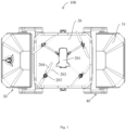
Fig. 1 shows a top view of a UAV base station in an open state according to one embodiment of the present disclosure; -
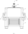
Fig. 2 shows a side view of a UAV base station in an open state according to one embodiment of the present disclosure; -
Fig. 3 shows a side view of a UAV base station in a closed state according to one embodiment of the present disclosure; -
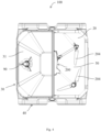
Fig. 4 shows a top view of a UAV base station in a closed state, wherein the protective cover on one side is removed, according to one embodiment of the present disclosure; -
Fig. 5 shows a three-dimensional view of a UAV base station in a closed state, wherein the protective cover on one side is removed, according to one embodiment of the present disclosure; -
Fig. 6 shows a top view of a UAV base station in an intermediate state according to one embodiment of the present disclosure; -
Fig. 7 shows a three-dimensional view of a UAV base station in an intermediate state according to one embodiment of the present disclosure; -
Fig. 8 shows a simplified structural schematic diagram of a translational drive mechanism according to one embodiment of the present disclosure; -
Fig. 9 shows a simplified structural schematic diagram of an active side rocker arm and a passive side rocker arm according to one embodiment of the present disclosure; -
Fig. 10 shows a schematic diagram of an embodiment of the present disclosure in which a heating member is provided on a protective cover. - The technical solutions in the embodiments of the present disclosure will be clearly and completely described below in conjunction with the accompanying drawings in the embodiments of the present disclosure, and it is clear that the described embodiments are only a part of the embodiments of the present disclosure and not all of the embodiments. Based on the embodiments in the present disclosure, all other embodiments obtained by a person of ordinary skill in the art without making creative labor fall within the scope of protection of the present disclosure.
- Exemplary embodiments will be described herein in detail, examples of which are represented in the accompanying drawings. When the following description relates to the accompanying drawings, the same numerals in the different accompanying drawings indicate the same or similar elements unless otherwise indicated. The embodiments described in the following exemplary embodiments do not represent all embodiments consistent with the present disclosure. Rather, they are only examples of devices and methods consistent with some aspects of the present disclosure as detailed in the appended claims.
- The terminology used in the present disclosure is for the sole purpose of describing particular embodiments and is not intended to limit the disclosure. The singular forms of "a" "an," and "the" as used in the present disclosure and appended claims are also intended to encompass the plurality form, unless the context clearly indicates otherwise. It should also be understood that the term "and/or" as used herein refers to and encompasses any or all possible combinations of one or more of the listed items in association. Unless otherwise noted, the terms "front," "rear," "lower," and/or "upper" and similar terms are used for convenience only and are not intended to be limited to a location or a spatial orientation. Words such as "connected" or "coupled" are not limited to physical or mechanical connections, but may include electrical connections, whether direct or indirect. "Capable" in the context of the present disclosure may denote the ability to.
- Various embodiments of the present disclosure are described in detail below in conjunction with the accompanying drawings. The features in the following embodiments and embodiments may be combined with each other without conflict.
- One embodiment of the present disclosure provides a
UAV base station 100.Figs. 1 and2 reveal a top view and a side view, respectively, of theUAV base station 100 in an open state of an embodiment of the present disclosure; andFigs. 3 to 5 reveal a side view, a top view, and a three-dimensional view, respectively, of theUAV base station 100 in a closed state of an embodiment of the present disclosure. InFigs. 4 and5 , in order to show more clearly the state in which the blades are folded in the accommodating space, the protective cover on one side is removed. As shown inFigs. 1 to 5 , theUAV base station 100 of one embodiment of the present disclosure includes abase body 10, alanding pad 20 disposed on thebase body 10, and a base station opening andclosing mechanism 30 movably disposed on thebase body 10. - The base station opening and
closing mechanism 30 includes an open state and a closed state. As shown inFigs. 1 and2 , when the base station opening andclosing mechanism 30 is in the open state, thelanding pad 20 is fully exposed and the UAV 200 may land on thelanding pad 20. As shown inFigs. 3 through 5 , when the base station opening andclosing mechanism 30 is in the closed state, anaccommodating space 50 that can be used to hold theUAV 200 is formed between the base station opening andclosing mechanism 30 and thelanding pad 20, and the base station opening andclosing mechanism 30 covers thelanding pad 20 completely, and thelanding pad 20 is fully contained within theaccommodating space 50. - The UAV 200 includes
foldable blades 204. and, when the UAV 200 lands on thelanding pad 20, the blades of theUAV 200 at least partially protrude outside of theaccommodating space 50. In some embodiments, after the UAV 200 lands on thelanding pad 20, the base station opening andclosing mechanism 30 of an embodiment of the present disclosure may actuate theblades 204 to fold within theaccommodating space 50 so that the UAV 200 is housed within theaccommodating space 50. - The
UAV base station 100 of the embodiment of the present disclosure can automatically drive the base station opening andclosing mechanism 30 to fold theblades 204 in theaccommodating space 50 during the process of closing the base station opening andclosing mechanism 30 after theUAV 200 lands on thelanding pad 20, thereby holding theUAV 200 as a whole in theaccommodating space 50. Thus, the area enclosed by the boundary of theaccommodating space 50 formed between the base station opening andclosing mechanism 30 and thelanding pad 20 during the closed state of the base station opening andclosing mechanism 30 can be greatly reduced relative to the projected area of the entire envelope of theUAV 200 as it is in the flight state. The area enclosed by the boundary of theaccommodating space 50 as described herein refers to the area formed by the projection of theaccommodating space 50 on a plane in which thelanding pad 20 is located. - Therefore, the size of the
UAV base station 100 of the embodiment of the disclosure can be greatly reduced relative to the existingUAV base station 100 designed with the projected area of the entire envelope, thereby enabling miniaturization of the product and reduction of the product cost and footprint. - As shown in
FIG. 1 , in some embodiments of the present disclosure, the UAV 200 comprises afuselage 201, anarm 202 disposed on thefuselage 201, and ablade drive motor 203 disposed at an end of thearm 202 for driving theblades 204 to rotate. In one embodiment, a pair ofblades 204 is disposed at an end of thearm 202, and theblade drive motor 203 can simultaneously drive the pair ofblades 204 to rotate. Of course, in other embodiments, only oneblade 204 may be provided at the end of thearm 202, and theblade drive motor 203 may drive the oneblade 204 to rotate. - Thus, in some embodiments, the area enclosed by the boundary of the
accommodating space 50 of theUAV base station 100 may be determined based on the projected area of theblade drive motors 203 on the plane in which thelanding pad 20 is located. The area enclosed by the boundary of theaccommodating space 50 is typically larger than the projected area of theblade drive motors 203 on the plane in which thelanding pad 20 is located. - The
UAV base station 100 of the embodiment of the present disclosure is capable of designing the size of the base station based on the projected area of theblades 204 of theUAV 200 on the plane where thelanding pad 20 is located, and collapsing theblades 204 in theaccommodating space 50 by changing the direction or the shape of theblades 204 or the like, so that the problem of theUAV base station 100 being oversized due to the size of theblades 204 can be avoided, and miniaturization of the base station can be realized. - In some embodiments, considering that the UAV 200 may not land accurately on the
landing pad 20 of theUAV base station 100 during actual landing, the area enclosed by the boundary of theaccommodating space 50 of theUAV base station 100 may be determined based on a combination of a projected area of theblade drive motors 203 on the plane where thelanding pad 20 is located and the landing accuracy of theUAV 200. If the landing accuracy of theUAV 200 can be made higher, the size of theUAV base station 100 will be able to be made smaller. - With continued reference to
FIG. 1 , it is shown that, in one embodiment, theUAV 200 may include fourarms 202, with twoarms 202 provided on each of the opposite sides of thefuselage 201. Ablade drive motor 203 and ablade 204 are provided at the end of eacharm 202, respectively. Eachblade drive motor 203 may, for example, drive a pair ofblades 204 to rotate, respectively. Thus, in this case, the boundary extent of theaccommodating space 50 of theUAV base station 100 may be determined based on the dimensions of a rectangle enclosed by the fourblade drive motors 203. Thus, theUAV base station 100 of the embodiment of the present disclosure can greatly reduce the size of the base station relative to existing UAV base stations designed with a complete projected envelope area of theentire UAV 200 including theblades 204. - As shown in
FIGS. 4 and5 , in some embodiments, theblades 204 of theUAV 200 housed in theaccommodating space 50 are in a stationary and retracted state while the base station opening andclosing mechanism 30 is in a closed state. In one embodiment, the retracted state described herein may be that theblades 204 are in a fully folded state. Of course, in other embodiments, the retracted state described herein does not necessarily require theblades 204 to be in a fully folded state, and the retracted state described herein may also be that theblades 204 are moved and folded relative to the fully unfolded state of the blades. For example, when the base station opening andclosing mechanism 30 is in the closed state, it is sufficient to make theblades 204 fold into the rectangle enclosed by the fourblade drive motors 203. Thereby, the projected area of theUAV 200 on the plane where thelanding pad 20 is located can be reduced, which in turn can reduce the boundary dimensions of theaccommodating space 50 of theUAV base station 100. - The following will describe in detail, in conjunction with
FIGS. 6 and7 , how the process of closing the cover of the base station opening andclosing mechanism 30 of theUAV base station 100 is accomplished to allow theblades 204 of theUAV 200 to retract after theUAV 200 has landed on thelanding pad 20. -
FIGS. 6 and7 reveal a three-dimensional schematic view of theUAV base station 100 of one embodiment of the present disclosure when it is in an intermediate state. As shown inFIGS. 6 and7 , the base station opening andclosing mechanism 30 also has an intermediate state that is located between the open state and the closed state. During the process of closing the cover of the base station opening andclosing mechanism 30, when the base station opening andclosing mechanism 30 closes the cover from the open state to the intermediate state, the base station opening andclosing mechanism 30 may touch theblade 204 and may push theblade 204 to gradually carry out the retracting. Thereby, when the base station opening andclosing mechanism 30 completely closes the cover in the closed state, theblades 204 of theUAV 200 are in the retracted state as shown inFIG. 3 . - The
UAV base station 100 of this embodiment of the disclosure further comprises a control system (not shown). - In order for the base station opening and
closing mechanism 30 to always be able to touch theblades 204 of theUAV 200 during the process of closing the cover, therefore, in some embodiments, when theUAV 200 lands on thelanding pad 20 and the base station opening andclosing mechanism 30 performs the closing of the cover, the control system of theUAV base station 100 may control theblades 204 of theUAV 200 to rotate at a low speed, that is, at a first speed, and control the base station opening andclosing mechanism 30 to slowly close the cover at a second speed. In one embodiment, the first speed of theblades 204 is greater than the second speed of the base station opening andclosing mechanism 30. Thereby, when the base station opening andclosing mechanism 30 closes the cover to an intermediate state, the base station opening andclosing mechanism 30 can just touch theblades 204 and push theblades 204 to retract. - As shown in
FIG. 6 , the control system may control theblades 204 to rotate toward the cover of the base station opening andclosing mechanism 30 when the base station opening andclosing mechanism 30 is closing the cover. The control system drives theblades 204 to rotate towards the direction of the closing cover of the base station opening andclosing mechanism 30 by controlling theblade drive motors 203 on each of thearms 202. For example, the rotational direction of theblades 204 on the fourarms 202 is shown as the direction of the arrows inFIG. 6 . - In some embodiments, the base station opening and
closing mechanism 30 may include a pair ofprotective covers 31, the pair ofprotective covers 31 being disposed symmetrically on opposite sides of thebase body 10. - In one embodiment, each
protective cover 31 is substantially in the form of a rectangular frame, theprotective cover 31 having atop wall 311, afirst sidewall 312, and two opposingsecond sidewalls 313, the twosecond sidewalls 313 being attached to opposite sides of thefirst sidewall 312, and thetop wall 311 being attached to thefirst sidewall 312 and to the two opposingsecond sidewalls 313, respectively, to thereby enclose a rectangular frame. - In the process of closing the cover of the base station opening and
closing mechanism 30, the twoprotective covers 31 respectively move relative to each other from the open state towards the closed state, and gradually approach each other. When the twoprotective covers 31 contact each other, the twoprotective covers 31 completely close the cover and are in the closed state. In the process of opening the cover of the base station opening andclosing mechanism 30, the twoprotective covers 31 respectively move relative to each other from the closed state toward the open state, and move away from each other. - As shown in
FIGS. 6 and7 , when the base station opening andclosing mechanism 30 is closed to an intermediate state, anend side surface 3130 of at least one of the twosecond sidewalls 313 of theprotective cover 31 touches theblade 204 and pushes theblade 204 to retract. - In the process of contacting between the
protective cover 31 and theblade 204, a line may be formed between the motor shaft of theblade drive motor 203 of theUAV 200, theblade 204 and the point at which thesecond side wall 313 of theprotective cover 31 comes into contact with theblade 204, which causes the line of action of the propelling force given by thesecond side wall 313 of theprotective cover 31 to pass through the motor shaft of theblade drive motor 203. Since an initial phase angle of theblade 204 is not restricted, at this time, the propelling force does not play the role of propelling the blade, but gives an additional push to the entire UAV. If theprotective cover 31 is continued to be driven to close at this time, there is a possibility of damaging theblades 204 or other components of theUAV 200, a situation that is commonly referred to as reaching a dead point of the motion in the mechanics of motion. Therefore, in order to prevent theprotective cover 31 and theblades 204 from reaching a kinematic dead point during the process of theprotective cover 31 touching theblades 204, as shown inFIGS. 6 and7 , in some embodiments, aflexible device 60 may be provided at the end side surface of eachsecond sidewall 313 of theprotective cover 31, which may be utilized to change the direction of the propelling force, which may be utilized to solve the problem of kinematic dead point. - As shown in
FIG. 8 , theUAV base station 100 of the embodiment of the present disclosure further comprises a drive mechanism, the drive mechanism comprising adrive motor 41 for driving the movement of theprotective cover 31. In other embodiments, the control system may also determine whether the dead point of the movement is reached by detecting the torque of thedrive motor 41, and the control system may control thedrive motor 41 to rotate positively or reversely. In one embodiment, the control system may detect the magnitude of the torque of thedrive motor 41 by the magnitude of the current value fed back by thedrive motor 41. If it appears that the current value fed back by thedrive motor 41 is abnormally high, such as the current value fed back by thedrive motor 41 is higher than a predetermined current value, when thesecond sidewall 313 of theprotective cover 31 touches theblade 204, it can be determined that theprotective cover 31 and theblade 204 have reached a dead point of movement in this case. Therefore, at this time, the control system may control thedrive motor 41 to first reverse and then forward, so that the movement dead point can be avoided. - In other embodiments, the control system may also detect a real-time position of the
blade 204 and theprotective cover 31, and may control at least one of a rotational speed of theblade 204 or a closing speed of theprotective cover 31 based on the real-time position of theblade 204 and theprotective cover 31, so as to avoid theprotective cover 31 and theblade 204 from reaching a dead point at the same time. - As shown in
FIG. 2 , a top surface of theprotective cover 31 may not be higher than thelanding pad 20 in order to prevent that theblades 204 of theUAV 200 may touch theprotective cover 31 when theUAV 200 lands on thelanding pad 20 when the base station opening andclosing mechanism 30 is in the open state. - In some embodiments, the drive mechanism for driving the opening and closing motion of the base station opening and
closing mechanism 30 of an embodiment of the present disclosure comprises a pair oftranslational drive mechanisms 40.FIG. 8 reveals a schematic diagram of thetranslational drive mechanisms 40 of an embodiment of the present disclosure. As shown inFIG. 8 , eachtranslational drive mechanism 40 is provided between a side of thebase body 10 and aprotective cover 31, and can be used to drive theprotective cover 31 to translate relative to thebase body 10. - In some embodiments, each
translational drive mechanism 40 includes adrive motor 41, amotor drive shaft 42, and a pair ofrocker arms 43. Themotor drive shaft 42 is provided on one side of thebase body 10, and both ends of themotor drive shaft 42 are respectively fixed to thebase body 10 viabearings 44. The pair ofrocker arms 43 are respectively provided on opposite sides of theprotective cover 31, and one end of eachrocker arm 43 is fixedly connected to one end of themotor drive shaft 42, and the other end is movably connected to theprotective cover 31. Thetranslational drive mechanism 40 further includes a protectivecover follower shaft 45. The protectivecover follower shaft 45 is movably disposed on theprotective cover 31, for example, the protectivecover follower shaft 45 may be fixed to theprotective cover 31 by means of abearing 46. When therocker arm 43 swings, theprotective cover 31 can rotate freely around the protectivecover follower shaft 45. Therein, the other end of therocker arm 43 is fixedly connected to the protectivecover follower shaft 45, thereby, realizing a movable connection between therocker arm 43 and theprotective cover 31. In one embodiment, both ends of therocker arm 43 are fixedly connected to themotor drive shaft 42 and the protectivecover follower shaft 45, respectively, by means offlange bolt 47 connections. - Wherein, the
drive motor 41 on each side of thebase body 10 can drive the pair ofrocker arms 43 to swing by rotating the drivemotor drive shaft 42, thereby driving theprotective cover 31 on that side to move. - In some embodiments, the
translational drive mechanism 40 may maintain an attitude of thetop wall 311 of theprotective cover 31 facing upward at all times during the opening and closing of theprotective cover 31. Thetranslational drive mechanism 40 also includes an attitude retention mechanism, and the attitude retention mechanism may be used to maintain the attitude of theprotective cover 31. - A pair of
rocker arms 43 of an embodiment of the present disclosure comprises an activeside rocker arm 431 and a passiveside rocker arm 432.FIG. 9 reveals a simplified structural schematic diagram of the activeside rocker arm 431 and the passiveside rocker arm 432 of an embodiment of the present disclosure. As shown inFIG. 9 , the attitude retention mechanism may be provided in the activeside rocker arm 431, while the attitude retention mechanism may not be provided in the passiveside rocker arm 432. Since theprotective cover 31 is usually made of a rigid material, the attitude retention mechanism provided in the activeside rocker arm 431 will give a holding force to thesecond side wall 313 of theprotective cover 31 located on the side of the activeside rocker arm 431 while also giving a holding force to thesecond side wall 313 of theprotective cover 31 located on the side of the passiveside rocker arm 432. Thesecond side wall 313 of theprotective cover 31 on the side of the passiveside rocker arm 432 is given a holding force, so that theprotective cover 31 always maintains a posture of thetop wall 311 of theprotective cover 31 facing upward during opening and closing. - In some embodiments, the attitude retention mechanism includes a
first sprocket 4311, asecond sprocket 4312, and achain 4313. Thefirst sprocket 4311 is secured to thebase body 10, and thesecond sprocket 4312 is secured to theprotective cover 31. Thefirst sprocket 4311 and thesecond sprocket 4312 are connected in tension by thechain 4313. Thefirst sprocket 4311 and thesecond sprocket 4312 are respectively co-centered with the ends of therocker arm 43. - When the
drive motor 41 on each side can drive therocker arm 43 to rotate via themotor drive shaft 42, thesecond sprocket 4312 can rotate with therocker arm 43 around thefirst sprocket 4311, and because of thechain 4313, thesecond sprocket 4312 can be kept in the same phase with thefirst sprocket 4311, which can make it possible for theprotective cover 31 to keep the attitude consistently the same in the process of opening and closing. - The
translational drive mechanism 40 of the embodiment of the present disclosure can realize a large angle swing of therocker arm 43, which can make the space above the landing plane of theUAV 200 clear, avoiding the interference of external factors causing theUAV 200 to collide. -
FIG. 9 reveals a schematic view of a structure of the passiveside rocker arm 432 of one embodiment of the present disclosure. As shown inFIG. 9 , since the attitude retention mechanism formed by thefirst sprocket 4311, thesecond sprocket 4312, and thechain 4313 is not provided in the passiveside rocker arm 432, in some embodiments, the alignments of the electronic components used for theprotective cover 31 can be arranged in theinternal cavity 4320 of the passiveside rocker arm 432. Thus, the internal space of theprotective cover 31 can be saved, the utilization of the space is high, the electronic components for theprotective cover 31 can be integrated in the top layout of the product, the product deployment is more convenient, and the product integration is high. - Electronic components such as antennas, cameras, etc. can be arranged on top of the
protective cover 31. - In some embodiments, at least one of an environmental monitoring device such as a rain gauge, an anemometer, a wind gauge, a temperature sensor, a humidity sensor, and the like may be arranged on the top of the
protective cover 31. In other embodiments, theUAV base station 100 may also include aweather station 90 that centralizes the functions of the multiple environmental monitoring devices in a single station, and theweather station 90 may be directly on top of theprotective cover 31. - Considering that when the
UAV base station 100 is deployed in a cold, rainy, or snowy region, theprotective cover 31 of theUAV base station 100 may be susceptible to being frozen by snow and ice and thus unable to be opened and closed, an ice-melting device may be designed around theprotective cover 31 of theUAV base station 100, so that unattended deployment can be realized globally. In some embodiments, theUAV base station 100 of an embodiment of the present disclosure may further comprise aheating member 70, wherein theheating member 70 may be used to heat the seams of the pair of protective covers 31. -
FIG. 10 reveals a schematic diagram of an embodiment of the present disclosure in which aheating member 70 is provided on aprotective cover 31. As shown inFIG. 10 , thetop wall 311 of one of the pair ofprotective covers 31 is provided with a convex bar (not labeled) extending outwardly, and a corresponding groove (not labeled) is provided at the lower end of thetop wall 311 of the otherprotective cover 31, and the convex bar is mated with the groove, and theheating member 70 is provided in the convex bar. - When the pair of
protective covers 31 is in a closed state with the cover completely closed, theheating member 70 is disposed at the seam of the pair ofprotective covers 31 and can heat the seam of the pair of protective covers 31. - The
heating member 70 is communicatively coupled to a control system, which can be used to control theheating member 70. In some embodiments, the control system can be used to control theheating member 70 based on theweather station 90 or based on the outdoor temperature read by the temperature sensor. When the control system determines that theprotective cover 31 is frozen with snow and ice based on theweather station 90 or based on the outdoor temperature read by the temperature sensor, the control system may control to turn on theheating member 70, so that the snow and ice at the crevices of theprotective cover 31 can be heated and melted so that theprotective cover 31 can be opened smoothly to adapt to global unattended deployment. Of course, in other embodiments, theprotective cover 31 of theUAV base station 100 may also be manually observed via a camera to see if theprotective cover 31 is frozen with ice. When theprotective cover 31 of theUAV base station 100 is observed to be iced over and frozen, theheating member 70 may be manually turned on to heat and melt the snow and ice at the seams of theprotective cover 31. - Embodiments of the present disclosure also provide a UAV system. The UAV system comprises a
UAV 200 and aUAV base station 100 as described in the above embodiments. - The UAV system of the embodiments of the present disclosure has beneficial technical effects that are substantially similar to those of the
UAV base station 100 described in the various embodiments above, and, therefore, will not be repeated herein. - It should be noted that, in this document, relational terms such as "first" and "second" are used only to distinguish one entity or operation from another, and do not necessarily require or imply the existence of any such actual relationship or order between those entities or operations. The terms "including", "comprising", or any other variant thereof, are intended to cover non-exclusive inclusion, such that a process, method, article or apparatus comprising a set of elements includes not only those elements, but also other elements not expressly listed. Or it also includes elements that are inherent to such process, method, article or apparatus. Without further limitation, the fact that an element is defined by the phrase "includes a ..." does not preclude the existence of another identical element in the process, method, article or apparatus that includes the element.
- The UAV base station and UAV system provided by the embodiments of the present disclosure are described in detail above, and specific examples are applied herein to illustrate the principles and implementations of the present disclosure, and the description of the above embodiments is only used to help understand the method of the present disclosure and its core ideas, and the contents of this specification shall not be construed as a limitation of the present disclosure. At the same time, for the general technical personnel in the field, based on the idea of the present disclosure, can make any modification, equivalent replacement or improvement on the specific implementation and application scope, which should be included in the scope of the claims of the present disclosure.
Claims (42)
- A UAV base station characterized in that it comprises:a base body;a landing pad, provided on the base body ; anda base station opening and closing mechanism movably disposed on the base body, the base station opening and closing mechanism comprising an open state and a closed state, a UAV capable of landing on the landing pad when the base station opening and closing mechanism is in the open state, and an accommodating space for housing the UAV being formed between the base station opening and closing mechanism and the landing pad when the base station opening and closing mechanism is in the closed state, the UAV comprising foldable blades, the blades at least partially protruding out of the accommodating space when the UAV lands on the landing pad, the base station opening and closing mechanism being actuatable to fold the blades within the accommodating space after the UAV has landed on the landing pad, so as to cause the UAV to be housed within the accommodating space .
- The UAV base station as claimed in claim 1, characterized in that the UAV comprises a fuselage, an arm disposed on the fuselage, and a blade drive motor disposed at an end of the arm for driving the blades to rotate, an area enclosed by a boundary of the accommodating space being determined based on an area of projection of the blade drive motor on a plane where the landing pad is located.
- The UAV base station as claimed in claim 2, characterized in that the area enclosed by the boundary of the accommodating space is greater than a projected area of the blade drive motors on the plane in which the landing pad is located.
- The UAV base station as claimed in claim 2 or 3, characterized in that the area enclosed by the boundary of the accommodating space is determined based on the projected area of the blade drive motors on the plane where the landing pad is located and landing accuracy of the UAV.
- The UAV base station as claimed in claim 2, characterized in that the arms comprise four, two the arms are provided on opposite sides of the fuselage, and the blade drive motors and the blades are provided at an end of each of the arms, and a bounding extent of the accommodating space is determined based on dimensions of a rectangle surrounded by the four the blade drive motors.
- The UAV base station as claimed in claim 5, characterized in that the blade drive motors and a pair of the blades are provided at the end of each the arm, each the blade drive motor driving a pair of the blades to rotate respectively.
- The UAV base station as claimed in claim 1, characterized in that the blades of the UAV housed in the accommodating space are in a stationary and retracted state when the base station opening and closing mechanism is in a closed state.
- The UAV base station as claimed in claim 1, characterized in that the base station opening and closing mechanism further has an intermediate state located between the open state and the closed state, wherein when the base station opening and closing mechanism is closed to the intermediate state, the base station opening and closing mechanism is in contact with the blades and can propel the blades for retracting.
- The UAV base station as claimed in claim 8, characterized in that it further comprises:a control system,wherein, at a time that the UAV of landing on the landing pad and the base station opening and closing mechanism of performing a closing of a cover, the control system controls the blades of the UAV to rotate at a first speed and controls the base station opening and closing mechanism to close the cover at a second speed, the first speed being greater than the second speed.
- The UAV base station as claimed in claim 9, characterized in that the control system controls the blades to rotate in a direction toward the cover of the base station opening and closing mechanism when the base station opening and closing mechanism is closing the cover.
- The UAV base station as claimed in claim 9 or 10, characterized in that the base station opening and closing mechanism comprises a pair of protective covers, the pair of protective covers being disposed symmetrically on opposite sides of the base body.
- The UAV base station as claimed in claim 11, characterized in that the protective cover has a top wall, a first side wall and two second side walls opposite each other, the two second side walls being connected to opposite sides of the first side wall, and the top wall being connected to the first side wall and to the two the second side walls opposite each other, respectively.
- The unmanned aerial vehicle base station as claimed in claim 12, characterized in that when the base station opening and closing mechanism is closed to the intermediate state, an end side surface of at least one of the two the second sidewalls of the protective cover touches the blades and pushes the blades to retract.
- The UAV base station as claimed in claim 13, characterized in that a flexible device for changing direction of a propelling force is provided in the end side surface of the second sidewall.
- The UAV base station as claimed in claim 11, characterized in that it further comprises:a drive mechanism, the drive mechanism comprising a drive motor for driving the protective cover in motion,wherein the control system is further used to detect a torque of the drive motor, and to control the drive motor to rotate forward or reverse based on a magnitude of the detected torque of the drive motor.
- The UAV base station as claimed in claim 15, characterized in that the control system detects the magnitude of the torque of the drive motor by a magnitude of a current value fed back from the drive motor.
- The UAV base station as claimed in claim 16, characterized in that in case the current value fed back by the drive motor is higher than a predetermined current value, then the control system controls the drive motor to reverse and then forward.
- The UAV base station as claimed in claim 11, characterized in that the control system is further used to detect a real-time position of the blades and the protective cover and to control at least one of a rotational speed of the blades and a closing speed of the protective cover based on the real-time position of the blades and the protective cover.
- The UAV base station as claimed in claim 1, characterized in that the base station opening and closing mechanism comprises a pair of protective covers, the pair of protective covers being disposed symmetrically on opposite sides of the base body.
- The UAV base station as claimed in claim 19, characterized in that a top surface of the protective cover is not higher than the landing pad when the base station opening and closing mechanism is in the open state.
- The UAV base station as claimed in claim 19 or 20, characterized in that it further comprises:
a pair of translational drive mechanisms, each the translational drive mechanism provided between a side of the base body and one the protective cover for driving the protective cover to translate relative to the base body. - The UAV base station as claimed in claim 21, characterized in that the translational drive mechanism comprises:a drive motor;a motor drive shaft, provided on one side of the base body; anda pair of rocker arms, each provided on opposite sides of the protective cover, one end of each the rocker arm being fixedly connected to one end of the motor drive shaft and the other end being movably connected to the protective cover,wherein the drive motor drives the pair of the rocker arms to swing by driving the motor drive shaft to rotate.
- The UAV base station as claimed in claim 22, characterized in that each end of the motor drive shaft is secured to the base body by bearings.
- The UAV base station as claimed in claim 22, characterized in that the translational drive mechanism further comprises:a protective cover follower shaft, movably provided on the protective cover, thewherein the other end of the rocker arm is fixedly connected to the protective cover follower shaft.
- The UAV base station as claimed in claim 24, characterized in that the ends of the rocker arm are fixedly connected to the motor drive shaft and the protective cover follower shaft, respectively, by means of flange bolt connections.
- The UAV base station as claimed in claim 24, characterized in that the protective cover follower shaft is secured to the protective cover by a bearing.
- The UAV base station as claimed in claim 22, characterized in that the protective cover has a top wall, a first side wall and two second side walls opposite each other, the two second side walls being connected to opposite sides of the first side wall, and the top wall being connected to the first side wall and to the two the second side walls opposite each other, respectively.
- The UAV base station as claimed in claim 27, characterized in that during the opening and closing of the protective cover, the translational drive mechanism is used to maintain a top wall of the protective cover in an upward facing attitude at all times.
- The UAV base station as claimed in claim 28, characterized in that a pair of the rocker arms comprises an active side rocker arm and a passive side rocker arm, the translational drive mechanism further comprising:
an attitude retention mechanism which is provided in the active side rocker arm for maintaining the attitude of the protective cover. - The UAV base station as claimed in claim 29, characterized in that the attitude retention mechanism comprises:a first sprocket, secured to the base body;a second sprocket, secured to the protective cover; anda chain.wherein the first sprocket and the second sprocket are connected in tension by the chain.
- The UAV base station as claimed in claim 30, characterized in that the second sprocket rotates with the rocker arm around the first sprocket and remains in phase with the first sprocket while the drive motor rotates the rocker arm via the motor drive shaft.
- The UAV base station as claimed in claim 30, characterized in that the first sprocket and the second sprocket are each co-centered with the ends of the rocker arm.
- The UAV base station as claimed in claim 29, characterized in that an alignment for electronic components on the protective cover is arranged in an internal cavity of the passive side rocker arm.
- The UAV base station as claimed in claim 19, characterized in that it further comprises:
a heating member that can be used to heat a seam of a pair of the protective covers. - The UAV base station as claimed in claim 34, characterized in that the top wall of the protective cover of one of the pair of the protective covers is provided with a convex bar extending outwardly, and a corresponding groove is provided at a lower end of the top wall of the other the protective cover, the convex bar mating with the groove, and the heating member being provided in the convex bar.
- The UAV base station as claimed in claim 34, characterized in that it further comprises:
a control system for controlling the heating member. - The UAV base station as claimed in claim 36, characterized in that it further comprises:
a weather station, disposed on top of the protective cover. - The unmanned aerial vehicle base station as claimed in claim 37, characterized in that the control system controls turning on of the heating member based on an outdoor temperature read by the weather station.
- The UAV base station as claimed in claim 19, characterized in that at least one of a rain gauge, an anemometer, a wind gauge, a temperature sensor, or a humidity sensor is arranged at the top of the protective cover.
- The UAV base station as claimed in claim 19, characterized in that an antenna is arranged at the top of the protective cover.
- The UAV base station as claimed in claim 19, characterized in that a camera is arranged at the top of the protective cover.
- A UAV system characterized in that it comprises a UAV and the UAV base station as claimed in any one of claims 1 to 41.
Applications Claiming Priority (1)
| Application Number | Priority Date | Filing Date | Title |
|---|---|---|---|
| PCT/CN2022/079906 WO2023168623A1 (en) | 2022-03-09 | 2022-03-09 | Unmanned aerial vehicle base station and unmanned aerial vehicle system |
Publications (3)
| Publication Number | Publication Date |
|---|---|
| EP4343082A1 true EP4343082A1 (en) | 2024-03-27 |
| EP4343082A4 EP4343082A4 (en) | 2024-07-31 |
| EP4343082B1 EP4343082B1 (en) | 2026-04-29 |
Family
ID=87936977
Family Applications (1)
| Application Number | Title | Priority Date | Filing Date |
|---|---|---|---|
| EP22930267.4A Active EP4343082B1 (en) | 2022-03-09 | 2022-03-09 | Unmanned aerial vehicle base station and unmanned aerial vehicle system |
Country Status (4)
| Country | Link |
|---|---|
| US (1) | US12391414B2 (en) |
| EP (1) | EP4343082B1 (en) |
| CN (1) | CN117897545B (en) |
| WO (1) | WO2023168623A1 (en) |
Families Citing this family (16)
| Publication number | Priority date | Publication date | Assignee | Title |
|---|---|---|---|---|
| US12280901B2 (en) * | 2019-10-15 | 2025-04-22 | Axon Enterprise, Inc. | Drone pod for receiving, storing, and presenting a drone |
| EP4343082B1 (en) * | 2022-03-09 | 2026-04-29 | SZ DJI Technology Co., Ltd. | Unmanned aerial vehicle base station and unmanned aerial vehicle system |
| US11884422B2 (en) | 2022-04-27 | 2024-01-30 | Skydio, Inc. | Base stations for unmanned aerial vehicles (UAVs) |
| CN116166074B (en) * | 2023-02-03 | 2025-08-08 | 深圳市道通智能航空技术股份有限公司 | Mode adjustment method and adjustment device of drone base station and drone base station |
| CN116119064A (en) * | 2023-02-03 | 2023-05-16 | 深圳市道通智能航空技术股份有限公司 | Unmanned aerial vehicle basic station and unmanned aerial vehicle system |
| CN117657505B (en) * | 2023-12-29 | 2025-09-23 | 蜂巢航宇科技(北京)有限公司 | An antifreeze device for drone hangar doors |
| US12344411B1 (en) * | 2024-04-03 | 2025-07-01 | Hoodman Corporation | Foldable launch and landing pad for drones |
| US12545447B1 (en) * | 2024-06-07 | 2026-02-10 | Amazon Technologies, Inc. | Aerial vehicle landing pad with sensors |
| US20260048866A1 (en) * | 2024-08-15 | 2026-02-19 | Skydio, Inc. | Landing platform in a base station for use with unmanned aerial vehicles and including drive brackets |
| US20260048877A1 (en) * | 2024-08-15 | 2026-02-19 | Skydio, Inc. | Base Station For An Unmanned Aerial Vehicle Including A Rotatable Roof Assembly |
| US20260048878A1 (en) * | 2024-08-15 | 2026-02-19 | Skydio, Inc. | Base Stations For Unmanned Aerial Vehicles And Stands For Use Therewith |
| CN119774031B (en) * | 2024-09-19 | 2026-01-06 | 比亚迪股份有限公司 | Unmanned aerial vehicle (UAV) take-off and landing equipment, UAV take-off and landing systems and vehicles |
| CN118850391B (en) * | 2024-09-25 | 2024-12-17 | 浙江华飞智能科技有限公司 | Unmanned aerial vehicle stop device |
| CN118850390B (en) * | 2024-09-25 | 2025-01-03 | 浙江华飞智能科技有限公司 | Blade retracting mechanism and drone parking device |
| CN119460229B (en) * | 2025-01-14 | 2025-04-22 | 泉州圣源警用侦察设备有限公司 | Quick detach formula mounting platform and pass through machine thereof |
| KR102950166B1 (en) * | 2025-07-24 | 2026-04-08 | 주식회사 일신전기 | Drone hangar |
Family Cites Families (322)
| Publication number | Priority date | Publication date | Assignee | Title |
|---|---|---|---|---|
| US3253806A (en) * | 1964-05-20 | 1966-05-31 | Eickmann Karl | Control means in a hydraulic driven helicopter |
| GB1120658A (en) * | 1967-04-20 | 1968-07-24 | Rolls Royce | Power plant for a helicopter |
| US4262712A (en) * | 1978-11-08 | 1981-04-21 | Exxon Research & Engineering Co. | Magnetically latchable liquid dispensing nozzle |
| DE10209881A1 (en) * | 2002-03-06 | 2003-09-18 | Aloys Wobben | aircraft |
| US20160286128A1 (en) * | 2002-10-01 | 2016-09-29 | Dylan TX ZHOU | Amphibious vtol super drone camera in a mobile case (phone case) with multiple aerial and aquatic flight modes for capturing panoramic virtual reality views, selfie and interactive video |
| US7140575B2 (en) * | 2003-01-17 | 2006-11-28 | The Insitu Group, Inc. | Methods and apparatuses for launching unmanned aircraft, including methods and apparatuses for releasably gripping aircraft during launch |
| US7114680B2 (en) * | 2003-01-17 | 2006-10-03 | The Insitu Group, Inc. | Methods and apparatuses for launching and capturing unmanned aircraft, including a combined launch and recovery system |
| US20040256519A1 (en) * | 2003-03-12 | 2004-12-23 | Ellis Stephen C. | System for recovery of aerial vehicles |
| GB2411209A (en) * | 2004-02-20 | 2005-08-24 | Rolls Royce Plc | Wind-driven power generating apparatus |
| US20060249622A1 (en) * | 2005-05-04 | 2006-11-09 | Lockheed Martin Corporation | Autonomous Environmental Control System and Method For Post-Capture and Pre-Launch Management of an Unmanned Air Vehicle |
| US7334755B2 (en) * | 2005-05-25 | 2008-02-26 | The Boeing Company | Tandem rotor wing and tandem fixed wing aircraft |
| US7699261B2 (en) * | 2007-03-05 | 2010-04-20 | Lockheed Martin Corporation | Small unmanned airborne vehicle airframe |
| US8205831B2 (en) * | 2007-09-04 | 2012-06-26 | Helidex Llc | Modular helicopter deck for offshore oil drilling/production platforms |
| US8336807B2 (en) * | 2008-01-09 | 2012-12-25 | Bernard Hanafin | Combined helicopter landing pad and clamshell enclosure |
| US8256172B2 (en) * | 2008-06-03 | 2012-09-04 | Christopher Benson | Modular free standing structure |
| US8052081B2 (en) * | 2008-08-22 | 2011-11-08 | Draganfly Innovations Inc. | Dual rotor helicopter with tilted rotational axes |
| US20100170993A1 (en) * | 2009-01-05 | 2010-07-08 | Kent Paul Misegades | Aerodynamic Fairing for aircraft lift strut |
| US8511606B1 (en) * | 2009-12-09 | 2013-08-20 | The Boeing Company | Unmanned aerial vehicle base station |
| US8297552B2 (en) * | 2010-01-21 | 2012-10-30 | I/O Controls Corporation | Helicopter landing pad |
| DE102010013219A1 (en) * | 2010-03-29 | 2011-09-29 | Airbus Operations Gmbh | Handling system for handling objects in a vehicle, storage device and method for handling objects in a vehicle |
| US8245469B2 (en) * | 2010-05-20 | 2012-08-21 | Aditazz, Inc. | Deck assembly module for a steel framed building |
| US9050997B1 (en) * | 2010-08-31 | 2015-06-09 | Michael R. Schramm | Rollover prevention apparatus |
| US20120080556A1 (en) * | 2010-10-05 | 2012-04-05 | Lockheed Martin Corporation | Systems and Methods for Autonomous Operations of Unmanned Aerial Vehicles |
| US9387940B2 (en) * | 2010-11-09 | 2016-07-12 | Colorado Seminary Which Owns And Operates The University Of Denver | Intelligent self-leveling docking system |
| DE102011014230A1 (en) * | 2011-03-17 | 2012-09-20 | Satisloh Ag | Device for fine machining of optically effective surfaces on in particular spectacle lenses |
| US20130233964A1 (en) * | 2012-03-07 | 2013-09-12 | Aurora Flight Sciences Corporation | Tethered aerial system for data gathering |
| EP2664539B1 (en) * | 2012-05-17 | 2018-07-18 | The Boeing Company | A method of and apparatus for extending the operation of an unmanned aerial vehicle |
| FR3000029B1 (en) * | 2012-12-21 | 2015-03-06 | Eads Europ Aeronautic Defence | INFLATABLE REFUELING DEVICES FOR AN ELECTRONIC STORAGE SYSTEM AND AIRCRAFT EQUIPPED WITH SUCH A DEVICE |
| US9513371B2 (en) * | 2013-02-28 | 2016-12-06 | Identified Technologies Corporation | Ground survey and obstacle detection system |
| US9429425B2 (en) * | 2013-03-05 | 2016-08-30 | Here Global B.V. | Aerial image collection |
| US9290269B2 (en) * | 2013-03-15 | 2016-03-22 | CyPhy Works, Inc. | Spooler for unmanned aerial vehicle system |
| US9852644B2 (en) * | 2013-03-24 | 2017-12-26 | Bee Robotics Corporation | Hybrid airship-drone farm robot system for crop dusting, planting, fertilizing and other field jobs |
| US10583920B2 (en) * | 2013-04-02 | 2020-03-10 | Hood Technology Corporation | Multicopter-assisted system and method for launching and retrieving a fixed-wing aircraft |
| EP2799336B1 (en) * | 2013-04-29 | 2020-03-18 | The Boeing Company | Device and method for use with unmanned aerial vehicles |
| US9457899B2 (en) * | 2013-06-24 | 2016-10-04 | The Boeing Company | Modular vehicle lift system |
| US9577445B2 (en) * | 2013-09-09 | 2017-02-21 | Olaeris, Inc. | Vehicle replenishment |
| US9815684B2 (en) * | 2013-11-01 | 2017-11-14 | Brian Kamradt | Fueling station for unmanned aerial vehicle of the vertical takeoff types |
| US9488487B2 (en) * | 2013-11-01 | 2016-11-08 | Yahoo! Inc. | Route detection in a trip-oriented message data communications system |
| US20150158599A1 (en) * | 2013-12-10 | 2015-06-11 | Michael Sisko | Robotic aerial vehicle delivery system and method |
| KR101842031B1 (en) * | 2013-12-11 | 2018-03-26 | 한화테크윈 주식회사 | Surveillance system |
| US20150175276A1 (en) * | 2013-12-19 | 2015-06-25 | Kenneth Lee Koster | Delivery platform for unmanned aerial vehicles |
| US10839336B2 (en) * | 2013-12-26 | 2020-11-17 | Flir Detection, Inc. | Unmanned delivery |
| US11066186B2 (en) * | 2014-01-02 | 2021-07-20 | Valqari Holdings, Llc | Receiving appliance for automated deliveries |
| EP3878319B1 (en) * | 2014-01-02 | 2025-03-19 | Valqari Holdings, Llc | Landing pad for unmanned aerial vehicle delivery |
| US9790640B2 (en) * | 2014-02-24 | 2017-10-17 | Gary S Selwyn | Composition and process for applying hydrophobic coating to fibrous substrates |
| US9643722B1 (en) * | 2014-02-28 | 2017-05-09 | Lucas J. Myslinski | Drone device security system |
| CN106200681B (en) * | 2014-03-27 | 2020-03-06 | 深圳市大疆创新科技有限公司 | Method and system for assisting take-off of movable object |
| GB2526517A (en) * | 2014-03-27 | 2015-12-02 | Malloy Aeronautics Ltd | Rotor-Lift Aircraft |
| US20150363843A1 (en) * | 2014-04-23 | 2015-12-17 | United Parcel Service Of America, Inc. | Dynamic provisioning of pick-up, delivery, transportation, and/or sortation options |
| US9561871B2 (en) * | 2014-05-07 | 2017-02-07 | Deere & Company | UAV docking system and method |
| US9412279B2 (en) * | 2014-05-20 | 2016-08-09 | Verizon Patent And Licensing Inc. | Unmanned aerial vehicle network-based recharging |
| EP3786742B1 (en) * | 2014-05-30 | 2025-02-19 | SZ DJI Technology Co., Ltd. | Systems and methods for uav docking |
| US9599992B2 (en) * | 2014-06-23 | 2017-03-21 | Nixie Labs, Inc. | Launch-controlled unmanned aerial vehicles, and associated systems and methods |
| US9499265B2 (en) * | 2014-07-02 | 2016-11-22 | Skycatch, Inc. | Unmanned aerial vehicle landing interface |
| US9932110B2 (en) * | 2014-07-22 | 2018-04-03 | Jonathan McNally | Method for installing an object using an unmanned aerial vehicle |
| WO2016015301A1 (en) * | 2014-07-31 | 2016-02-04 | SZ DJI Technology Co., Ltd. | Unmanned aerial vehicle base station system and method |
| US9704409B2 (en) * | 2014-08-05 | 2017-07-11 | Qualcomm Incorporated | Piggybacking unmanned aerial vehicle |
| US9573701B2 (en) * | 2014-08-06 | 2017-02-21 | Disney Enterprises, Inc. | Robust and autonomous docking and recharging of quadrotors |
| US11001358B2 (en) * | 2014-08-10 | 2021-05-11 | Merton W. Pekrul | Paddle wheel apparatus and method of use thereof |
| US10876470B2 (en) * | 2014-08-10 | 2020-12-29 | Merton W. Pekrul | Dynamic rotary engine vane force actuation apparatus including vane with stressed sheet |
| US10202849B2 (en) * | 2014-08-10 | 2019-02-12 | Merton W. Pekrul | Rotary engine vane drive method and apparatus |
| US9359074B2 (en) * | 2014-09-08 | 2016-06-07 | Qualcomm Incorporated | Methods, systems and devices for delivery drone security |
| US10196155B2 (en) * | 2014-09-09 | 2019-02-05 | Joseph Martin | Unmanned aerial delivery system |
| US9731821B2 (en) * | 2014-09-10 | 2017-08-15 | International Business Machines Corporation | Package transport by unmanned aerial vehicles |
| US9446858B2 (en) * | 2014-09-18 | 2016-09-20 | Kevin Hess | Apparatus and methods for tethered aerial platform and system |
| US9545852B2 (en) * | 2014-10-02 | 2017-01-17 | Swift Engineering, Inc. | Transportable ground station for an unmanned aerial vehicle |
| WO2016059555A1 (en) * | 2014-10-13 | 2016-04-21 | Systems Engineering Associates Corporation | Systems and methods for deployment and operation of vertical take-off and landing (vtol) unmanned aerial vehicles |
| US9623968B2 (en) * | 2014-11-11 | 2017-04-18 | Jon RIMANELLI | Unmanned air-ground vehicle |
| WO2016078025A1 (en) * | 2014-11-19 | 2016-05-26 | 深圳市大疆创新科技有限公司 | Positioning mechanism, uav base station using the positioning mechanism, and uav replenishment method |
| US9896202B2 (en) * | 2014-12-03 | 2018-02-20 | X Development Llc | Systems and methods for reliable relative navigation and autonomous following between unmanned aerial vehicle and a target object |
| US9840340B2 (en) * | 2014-12-09 | 2017-12-12 | Dan O'Toole | Drone docking station and delivery system |
| US9527605B1 (en) * | 2014-12-18 | 2016-12-27 | Amazon Technologies, Inc. | Multi-use unmanned aerial vehicle docking station |
| US9387928B1 (en) * | 2014-12-18 | 2016-07-12 | Amazon Technologies, Inc. | Multi-use UAV docking station systems and methods |
| US9984347B2 (en) * | 2014-12-30 | 2018-05-29 | Frank Dreano, JR. | System and method for enhancing distribution logistics and increasing surveillance ranges with unmanned aerial vehicles and a dock network |
| CN105235891B (en) * | 2015-01-04 | 2020-02-14 | 北京零零无限科技有限公司 | Folding unmanned aerial vehicle |
| US10358214B2 (en) * | 2015-01-04 | 2019-07-23 | Hangzhou Zero Zro Technology Co., Ltd. | Aerial vehicle and method of operation |
| US10719080B2 (en) * | 2015-01-04 | 2020-07-21 | Hangzhou Zero Zero Technology Co., Ltd. | Aerial system and detachable housing |
| US9915956B2 (en) * | 2015-01-09 | 2018-03-13 | Workhorse Group Inc. | Package delivery by means of an automated multi-copter UAS/UAV dispatched from a conventional delivery vehicle |
| US10071803B2 (en) * | 2015-01-16 | 2018-09-11 | International Business Machines Corporation | Package transport container and transport operations for an unmanned aerial vehicle |
| CN115158661B (en) * | 2015-01-18 | 2026-04-28 | 基础制造有限公司 | Devices, systems and methods for unmanned aerial vehicles |
| IL237130A0 (en) * | 2015-02-05 | 2015-11-30 | Ran Krauss | Landing and charging system for drones |
| WO2016130847A1 (en) * | 2015-02-11 | 2016-08-18 | Aerovironment, Inc. | Pod launch and landing system for vertical take-off and landing (vtol) unmanned aerial vehicles (uavs) |
| WO2016130721A2 (en) * | 2015-02-11 | 2016-08-18 | Aerovironment, Inc. | Survey migration system for vertical take-off and landing (vtol) unmanned aerial vehicles (uavs) |
| WO2016130797A1 (en) * | 2015-02-11 | 2016-08-18 | Aerovironment, Inc. | Pod cover system for a vertical take-off and landing (vtol) unmanned aerial vehicle (uav) |
| WO2016130711A1 (en) * | 2015-02-11 | 2016-08-18 | Aerovironment, Inc. | Pod operating system for a vertical take-off and landing (vtol) unmanned aerial vehicle (uav) |
| US9880563B2 (en) * | 2015-02-11 | 2018-01-30 | Aerovironment, Inc. | Geographic survey system for vertical take-off and landing (VTOL) unmanned aerial vehicles (UAVs) |
| WO2016130855A1 (en) * | 2015-02-12 | 2016-08-18 | Aerovironment, Inc. | Power and communication interface for vertical take-off and landing (vtol) unmanned aerial vehicles (uavs) |
| US11480958B2 (en) * | 2015-02-19 | 2022-10-25 | Amazon Technologies, Inc. | Collective unmanned aerial vehicle configurations |
| WO2017146685A1 (en) * | 2015-02-23 | 2017-08-31 | Weller Aaron | Enclosed unmanned aerial vehicle |
| US9540121B2 (en) * | 2015-02-25 | 2017-01-10 | Cisco Technology, Inc. | Pre-flight self test for unmanned aerial vehicles (UAVs) |
| US10287034B2 (en) * | 2015-03-02 | 2019-05-14 | American Robotics, Inc. | Drone aircraft landing and docking systems |
| KR20160112252A (en) * | 2015-03-18 | 2016-09-28 | 엘지전자 주식회사 | Unmanned air device and method of controlling the same |
| US9592908B2 (en) * | 2015-03-18 | 2017-03-14 | Amazon Technologies, Inc. | Adjustable landing gear assembly for unmanned aerial vehicles |
| US9714088B2 (en) * | 2015-03-27 | 2017-07-25 | Amazon Technologies, Inc. | Unmanned vehicle rollback |
| US9927682B2 (en) * | 2015-03-31 | 2018-03-27 | Vantage Robotics, Llc | Miniature stabilized unmanned aerial vehicle gimbal |
| WO2016170766A1 (en) * | 2015-04-20 | 2016-10-27 | 日本電気株式会社 | Light irradiation device and light irradiation system |
| US10023057B2 (en) * | 2015-04-22 | 2018-07-17 | Cristian A. Sobota Rodriguez | Contactless charger and battery management |
| GB201507392D0 (en) * | 2015-04-30 | 2015-06-17 | Yearwood Clebert O R | Surveillance vehicle |
| US9944366B2 (en) * | 2015-05-19 | 2018-04-17 | Rujing Tang | Unmanned aerial vehicle system and methods for use |
| WO2016196093A1 (en) * | 2015-06-01 | 2016-12-08 | Stoman Nicolaas | Systems, methods, and apparatuses for managing aerial drone parcel transfers |
| US10179648B2 (en) * | 2015-06-08 | 2019-01-15 | Howard Martin Chin | Airborne drone launch and recovery apparatus |
| US10453348B2 (en) * | 2015-06-15 | 2019-10-22 | ImageKeeper LLC | Unmanned aerial vehicle management |
| US9878787B2 (en) * | 2015-07-15 | 2018-01-30 | Elwha Llc | System and method for operating unmanned aircraft |
| CA2898304C (en) * | 2015-07-23 | 2020-01-07 | Simon Tremblay | Multifunctional motorized box and landing pad for automatic drone package delivery |
| WO2017019728A1 (en) * | 2015-07-27 | 2017-02-02 | Xworks Corporation | Method for unattended operations using autonomous or remotely operated vehicles |
| US20170158353A1 (en) * | 2015-08-07 | 2017-06-08 | Mark Schmick | Remote Aerodrome for UAVs |
| JP6908937B2 (en) * | 2015-08-17 | 2021-07-28 | エイチ3 ダイナミックス ホールディングス プライベート リミテッド | Drone box |
| US10633115B2 (en) * | 2015-08-17 | 2020-04-28 | Skyyfish, LLC | Autonomous system for unmanned aerial vehicle landing, charging and takeoff |
| WO2017049183A1 (en) * | 2015-09-18 | 2017-03-23 | Nixie Labs, Inc. | Stowable unmanned aerial vehicles and associated systems and methods |
| JP2018529571A (en) * | 2015-09-23 | 2018-10-11 | ウォルマート アポロ,エルエルシー | Portable unmanned delivery aircraft launch system and method of delivering product using aircraft launch system |
| US10099561B1 (en) * | 2015-09-25 | 2018-10-16 | Amazon Technologies, Inc. | Airborne unmanned aerial vehicle charging |
| US9421869B1 (en) * | 2015-09-25 | 2016-08-23 | Amazon Technologies, Inc. | Deployment and adjustment of airborne unmanned aerial vehicles |
| US9776717B2 (en) * | 2015-10-02 | 2017-10-03 | The Boeing Company | Aerial agricultural management system |
| WO2017062418A1 (en) * | 2015-10-05 | 2017-04-13 | Asylon, Inc. | Methods and apparatus for reconfigurable power exchange for multiple uav types |
| US11091275B2 (en) * | 2015-10-22 | 2021-08-17 | Droneovation, Inc. | Aerial drone operations support base |
| MX2018005347A (en) * | 2015-10-28 | 2018-09-21 | Walmart Apollo Llc | Apparatus and method for providing package release to unmanned aerial system. |
| US10878362B2 (en) * | 2015-11-05 | 2020-12-29 | United Parcel Service Of America, Inc. | Connection-based or communication-based services and determinations |
| CN108290633A (en) * | 2015-11-10 | 2018-07-17 | 马特耐特公司 | The method and system transported using unmanned aviation carrier |
| US9589448B1 (en) * | 2015-12-08 | 2017-03-07 | Micro Apps Group Inventions, LLC | Autonomous safety and security device on an unmanned platform under command and control of a cellular phone |
| CN105667768B (en) * | 2015-12-31 | 2017-11-14 | 歌尔科技有限公司 | A kind of unmanned plane rising and dropping control system and control method |
| AU2017200186A1 (en) * | 2016-01-16 | 2017-08-03 | Dometic Sweden Ab | Parking cooler |
| WO2017136776A1 (en) * | 2016-02-05 | 2017-08-10 | Vantage Robotics, Llc | Durable modular unmanned aerial vehicle |
| KR101757442B1 (en) * | 2016-02-22 | 2017-07-12 | 하이리움산업(주) | Fuel Cell Power-pack for Multi-copter |
| US10040578B2 (en) * | 2016-02-26 | 2018-08-07 | Skycatch, Inc. | Battery arm sensor assembly |
| US10607026B2 (en) * | 2016-03-21 | 2020-03-31 | Acronis International Gmbh | System and method for data backup using unmanned aerial vehicle (UAV) |
| US12030629B2 (en) * | 2016-03-24 | 2024-07-09 | Teledyne Flir Detection, Inc. | Cellular communication devices and methods |
| US11977395B2 (en) * | 2016-03-24 | 2024-05-07 | Teledyne Flir Defense, Inc. | Persistent aerial communication and control system |
| US20170275025A1 (en) * | 2016-03-24 | 2017-09-28 | GE Lighting Solutions, LLC | Luminaire-mounted landing platform for a drone |
| US20170283090A1 (en) * | 2016-04-04 | 2017-10-05 | Skycatch, Inc. | Unmanned aerial vehicle battery swapping system |
| US10994833B2 (en) * | 2016-04-06 | 2021-05-04 | Harris Aerial Llc | Heavy-lift unmanned aerial vehicle landing gear system |
| US20170308850A1 (en) * | 2016-04-22 | 2017-10-26 | United Parcel Service Of America, Inc. | Generating notifications using logical groupings |
| US20170305575A1 (en) * | 2016-04-24 | 2017-10-26 | Flytrex Aviation Ltd. | Payload funnel |
| US10730626B2 (en) * | 2016-04-29 | 2020-08-04 | United Parcel Service Of America, Inc. | Methods of photo matching and photo confirmation for parcel pickup and delivery |
| CN114228599B (en) * | 2016-04-29 | 2023-11-17 | 深圳市大疆创新科技有限公司 | System and method for unmanned aerial vehicle transportation and data acquisition |
| US10726381B2 (en) * | 2016-04-29 | 2020-07-28 | United Parcel Service Of America, Inc. | Methods for dispatching unmanned aerial delivery vehicles |
| US10417469B2 (en) * | 2016-05-07 | 2019-09-17 | Morgan E. Davidson | Navigation using self-describing fiducials |
| US9873408B2 (en) * | 2016-05-11 | 2018-01-23 | Peter D. Capizzo | Device for refueling, exchanging, and charging power sources on remote controlled vehicles, UAVs, drones, or any type of robotic vehicle or machine with mobility |
| US10773822B2 (en) * | 2016-05-29 | 2020-09-15 | Neoex Systems, Inc. | System and method for the transfer of cryogenic fluids |
| US10710746B2 (en) * | 2016-07-29 | 2020-07-14 | Stabilis Inc. | Ground station and tether for unmanned aerial vehicles |
| US10007272B2 (en) * | 2016-08-04 | 2018-06-26 | Echostar Technologies International Corporation | Midair tethering of an unmanned aerial vehicle with a docking station |
| US11325702B2 (en) * | 2016-08-19 | 2022-05-10 | Motorola Solutions, Inc. | Tethered aerial drone system |
| KR101858619B1 (en) * | 2016-08-24 | 2018-05-17 | 한국과학기술원 | Three-phase AC power wirelessly-chargable unmanned aerial vehicle and three-phase AC power wirelessly-charging apparatus for the same |
| US10176722B1 (en) * | 2016-08-29 | 2019-01-08 | Amazon Technologies, Inc. | Location marker with lights |
| DE102016117611B4 (en) * | 2016-09-19 | 2020-03-05 | Airrobot Gmbh & Co. Kg | Device for the air transport of an object |
| DE112016007161T5 (en) * | 2016-09-26 | 2019-05-09 | Ford Global Technologies, Llc | DRONES CARRIAGES |
| US10467685B1 (en) * | 2016-10-01 | 2019-11-05 | Stuart Brisson | System and device for rental dispensing of UAVs |
| CA3036706A1 (en) * | 2016-10-04 | 2018-04-12 | Walmart Apollo, Llc | Landing pad receptacle for package delivery and receipt |
| KR101851596B1 (en) * | 2016-10-07 | 2018-04-24 | 주식회사 진흥테크 | unmanned aerial vehicle and charging station for unmanned aerial vehicle |
| US20200286034A1 (en) * | 2017-09-25 | 2020-09-10 | Shmuel Ur Innovation Ltd | Drone based delivery system using vehicles |
| US11027595B2 (en) * | 2016-10-13 | 2021-06-08 | Dometic Sweden Ab | Roof fan assembly |
| WO2018076047A1 (en) * | 2016-10-24 | 2018-05-03 | Hybridskys Technology Pty Ltd | Hybrid aircraft |
| US11296522B2 (en) * | 2016-10-28 | 2022-04-05 | Telefonaktiebolaget Lm Ericsson (Publ) | Stackable automated drone charging station |
| JP6571739B2 (en) * | 2016-10-28 | 2019-09-04 | エム ルッソ ジョン | Liquid transport by unmanned aerial vehicle, method and system thereof |
| JP6683587B2 (en) * | 2016-11-07 | 2020-04-22 | 株式会社荏原製作所 | Wired drones |
| US10410105B1 (en) * | 2016-11-11 | 2019-09-10 | Ingar LLC | Containers for aerial drone transport of materials, objects, or products |
| FR3059647B1 (en) * | 2016-12-02 | 2021-11-12 | Elistair | SYSTEM INCLUDING A DRONE, A WIRE, AND A RECEPTION STATION, ALLOWING AUTONOMOUS LANDINGS OF THE DRONE IN DEGRADED CONDITION. |
| EP3568354B1 (en) * | 2017-01-10 | 2023-03-15 | Aurora Flight Sciences Corporation | Vertical lift by series hybrid-propulsion |
| US10127822B2 (en) * | 2017-02-13 | 2018-11-13 | Qualcomm Incorporated | Drone user equipment indication |
| US10310501B2 (en) * | 2017-02-15 | 2019-06-04 | International Business Machines Corporation | Managing available energy among multiple drones |
| US20180237161A1 (en) * | 2017-02-21 | 2018-08-23 | Echostar Technologies L.L.C. | Systems and methods for uav docking and recharging |
| US11294397B2 (en) * | 2017-02-24 | 2022-04-05 | Teledyne Fur Detection, Inc. | Control systems for unmanned aerial vehicles |
| US20180354649A1 (en) * | 2017-03-08 | 2018-12-13 | Mesa Digital, Llc | Drone recovery system |
| US20200398999A1 (en) * | 2017-03-08 | 2020-12-24 | Ip Venue, Llc | Secure recovery system for drone delivered packages |
| US9718564B1 (en) * | 2017-03-16 | 2017-08-01 | Amazon Technologies, Inc. | Ground-based mobile maintenance facilities for unmanned aerial vehicles |
| US10421542B2 (en) * | 2017-03-16 | 2019-09-24 | Amazon Technologies, Inc. | Mobile fulfillment centers with intermodal carriers and unmanned aerial vehicles |
| US10384692B2 (en) * | 2017-03-16 | 2019-08-20 | Amazon Technologies, Inc. | Demand-based distribution of items using intermodal carriers and unmanned aerial vehicles |
| CA3060413A1 (en) * | 2017-04-27 | 2018-11-01 | Ralph Irad Miller | Systems, methods, and devices improving safety and functionality of craft having one or more rotors |
| CN108513685A (en) * | 2017-05-02 | 2018-09-07 | 深圳市大疆创新科技有限公司 | A temperature control system for a base station and a temperature control method for a base station |
| JP6918976B2 (en) * | 2017-05-05 | 2021-08-11 | エスゼット ディージェイアイ テクノロジー カンパニー リミテッドSz Dji Technology Co.,Ltd | Systems and methods for transformable unmanned aerial vehicles |
| US11111033B1 (en) * | 2017-05-12 | 2021-09-07 | Phirst Technologies, Llc | Unmanned aerial vehicle recharging system |
| US11279481B2 (en) * | 2017-05-12 | 2022-03-22 | Phirst Technologies, Llc | Systems and methods for tracking, evaluating and determining a response to emergency situations using unmanned airborne vehicles |
| US10713958B2 (en) * | 2017-06-13 | 2020-07-14 | Benchmark Electronics, Inc. | Automated landing solution systems and methods |
| WO2018236903A1 (en) * | 2017-06-20 | 2018-12-27 | Planck Aerosystems Inc. | Systems and methods for charging unmanned aerial vehicles on a moving platform |
| US10745102B2 (en) * | 2017-07-17 | 2020-08-18 | Griff Aviation As | Swingable arm mount for an aerial vehicle having a lift generating means, and an aerial vehicle, advantageously a multicopter with a swingable arm mount |
| US10899473B2 (en) * | 2017-07-17 | 2021-01-26 | Christopher Julian Scherz | Docking station for unmanned aerial vehicles |
| US10292055B2 (en) * | 2017-07-18 | 2019-05-14 | Centurylink Intellectual Property Llc | Method and system for implementing self organizing mobile network (SOMNET) of drones |
| US10882410B2 (en) * | 2017-07-19 | 2021-01-05 | Wing Aviation Llc | Systems for charging aerial vehicles |
| EP3655324B1 (en) * | 2017-07-21 | 2025-07-23 | Sentien Robotics, Inc. | Uav retrieval and deployment system |
| US10099785B1 (en) * | 2017-07-25 | 2018-10-16 | Oswaldo Gonzalez | Drone with ring assembly |
| CN207029853U (en) * | 2017-07-28 | 2018-02-23 | 长春草莓科技有限公司 | A kind of storage device of unmanned plane propeller |
| EP3661847A1 (en) * | 2017-08-01 | 2020-06-10 | Zipline International Inc. | Unmanned aircraft system with swappable components |
| US9957045B1 (en) * | 2017-09-03 | 2018-05-01 | Brehnden Daly | Stackable drones |
| GB201812471D0 (en) * | 2017-09-13 | 2018-09-12 | Flirtey Holdings Inc | Positioning mechanism |
| US10526094B2 (en) * | 2017-09-29 | 2020-01-07 | Coretronic Intelligent Robotics Corporation | Platform |
| US20190100108A1 (en) * | 2017-09-29 | 2019-04-04 | Qualcomm Incorporated | Robotic Vehicle Renewable Resource Charging Station Management Systems and Methods |
| US10618656B2 (en) * | 2017-10-04 | 2020-04-14 | Textron Innovations Inc. | Tiltrotor aircraft having interchangeable payload modules |
| JP6832265B2 (en) * | 2017-10-05 | 2021-02-24 | 本田技研工業株式会社 | Flying object storage system |
| US11074540B2 (en) * | 2017-10-10 | 2021-07-27 | Uber Technologies, Inc. | Network system including drones |
| DE112017007933B4 (en) * | 2017-10-16 | 2025-06-26 | Ford Global Technologies, Llc | Landing platform and procedures |
| DE102017124351A1 (en) * | 2017-10-18 | 2019-04-18 | Rheinmetall Waffe Munition Gmbh | decoys |
| US10268208B1 (en) * | 2017-10-26 | 2019-04-23 | Amazon Technologies, Inc. | Gust resistant location marker |
| JP6829677B2 (en) * | 2017-11-21 | 2021-02-10 | 本田技研工業株式会社 | Charging device |
| GB2568962A (en) * | 2017-12-04 | 2019-06-05 | Idu Drop Ltd | A package receiving and returning device |
| CA2988156A1 (en) * | 2017-12-08 | 2019-06-08 | Quanta Associates, L.P. | Unmanned aerial vehicle for use near high voltage power lines |
| US10974911B2 (en) * | 2017-12-22 | 2021-04-13 | Wing Aviation Llc | Replenishment station for aerial vehicle with robotic device and conveyor |
| WO2019144080A1 (en) * | 2018-01-22 | 2019-07-25 | Krasnoff Curren | Drone systems and methods |
| US10472064B2 (en) * | 2018-01-29 | 2019-11-12 | Yu Tian | VTOL fixed-wing aerial drone with interchangeable cabins |
| US20190233103A1 (en) * | 2018-01-31 | 2019-08-01 | Walmart Apollo, Llc | Temporary uav delivery tower |
| EP3749578B1 (en) * | 2018-02-05 | 2023-03-15 | H3 Dynamics Holdings Pte. Ltd. | Landing platform with improved charging for unmanned aerial vehicles |
| US20190256202A1 (en) * | 2018-02-19 | 2019-08-22 | Parallel Flight Technologies, Inc. | Method and apparatus for lifting a payload |
| WO2019164554A1 (en) * | 2018-02-20 | 2019-08-29 | Global Energy Transmission, Co. | Rotor assembly with overlapping rotors |
| US11498700B2 (en) * | 2018-03-02 | 2022-11-15 | Verity Ag | Charging system and tray for flying machines |
| US10710716B2 (en) * | 2018-03-15 | 2020-07-14 | T-Mobile Usa, Inc. | Inhibiting cable entanglement in tethered drones |
| US10676284B2 (en) * | 2018-03-23 | 2020-06-09 | Corverity Corporation | Window-based delivery apparatus for packages conveyed by drones |
| US11148805B2 (en) * | 2018-04-10 | 2021-10-19 | Government Of The United States, As Represented By The Secretary Of The Army | Enclosure for an unmanned aerial system |
| TWM567744U (en) * | 2018-04-13 | 2018-10-01 | 龔日鴻 | Shareable energy module replacement system for unmanned aerial vehicle |
| JP7015734B2 (en) * | 2018-05-14 | 2022-02-03 | 株式会社東芝 | Transmission equipment, mobiles and wireless power transmission equipment |
| NO344486B1 (en) * | 2018-06-07 | 2020-01-13 | FLIR Unmanned Aerial Systems AS | System and method for storing and remotely launching unmanned aerial vehicles |
| US11898368B2 (en) * | 2018-06-14 | 2024-02-13 | Wing Aviation Llc | Unmanned aerial vehicle housing including deployable landing pads |
| US11155363B2 (en) * | 2018-06-15 | 2021-10-26 | Michael A. BAKLYCKI | Self-leveling launch and recovery platform for aerial vehicle and method of maintaining a level platform during launch and recovery |
| CN108945502B (en) * | 2018-06-29 | 2020-06-09 | 长春草莓科技有限公司 | An automatic storage device for unmanned aerial vehicles that can reduce the volume |
| US10960988B2 (en) * | 2018-07-16 | 2021-03-30 | The Boeing Company | Delivery landing pads for unmanned aerial vehicles (UAVs) |
| WO2020019109A1 (en) * | 2018-07-23 | 2020-01-30 | 上海峰飞航空科技有限公司 | Landing platform and method for unmanned aerial vehicle, and charging system |
| US11509203B2 (en) * | 2018-07-25 | 2022-11-22 | Moog Inc. | Claw-pole motor with rotor flux concentrators and poles and stator with solenoid coil and alternating stator teeth |
| US20200055613A1 (en) * | 2018-08-20 | 2020-02-20 | Ralph Irad Miller | Systems, methods, and devices for improving safety and functionality of craft having one or more rotors |
| US11079752B1 (en) * | 2018-08-30 | 2021-08-03 | Martin Lombardini | UAV controller device |
| EP3844025A1 (en) * | 2018-08-31 | 2021-07-07 | United Parcel Service Of America, Inc. | Systems, methods, and apparatuses for shifting and staging storage structures and parcels thereon |
| CN110785354A (en) * | 2018-09-12 | 2020-02-11 | 深圳市大疆创新科技有限公司 | Base station, control method of unmanned aerial vehicle and unmanned aerial vehicle system |
| US12162626B2 (en) * | 2018-09-18 | 2024-12-10 | H3 Dynamics Holdings Pte. Ltd. | Unmanned vehicle |
| US11124297B2 (en) * | 2018-09-21 | 2021-09-21 | Ford Global Technologies, Llc | Portable and vehicle-integrated storage and deployment system for unmanned aerial vehicle |
| US20190047462A1 (en) * | 2018-09-25 | 2019-02-14 | Intel Corporation | Modular configurable platform architecture for ca/ad vehicles |
| US11142447B2 (en) * | 2018-12-10 | 2021-10-12 | Textron Innovations Inc. | Mobile autonomous hydrogen refueling station |
| US11106224B2 (en) * | 2019-01-09 | 2021-08-31 | Ford Global Technologies, Llc | Multi-drone automotive systems and methods of use |
| CN111483386A (en) * | 2019-01-28 | 2020-08-04 | 中光电智能机器人股份有限公司 | Monitoring system, base station and control method thereof |
| US20200247540A1 (en) * | 2019-02-04 | 2020-08-06 | The Boeing Company | Self-defense weapons pod systems and methods for aircraft |
| WO2020163270A1 (en) * | 2019-02-06 | 2020-08-13 | Laitram, L.L.C. | Modular conveyor belt with hook hinges |
| US11518542B2 (en) * | 2019-02-15 | 2022-12-06 | Hoverfly Technologies, Inc. | Landing structure for an unmanned aerial vehicle |
| US20200290752A1 (en) * | 2019-03-11 | 2020-09-17 | Igor M. Kolosiuk | Autonomous hanging storage, docking and charging multipurpose station for an unmanned aerial vehicle |
| US11572197B1 (en) * | 2019-03-15 | 2023-02-07 | Alarm.Com Incorporated | Stations for unmanned aerial vehicles |
| US11287835B2 (en) * | 2019-03-21 | 2022-03-29 | Wing Aviation Llc | Geo-fiducials for UAV navigation |
| USD903576S1 (en) * | 2019-03-28 | 2020-12-01 | Sfid Llc | Cockpit |
| US11597516B1 (en) * | 2019-04-25 | 2023-03-07 | The United States Of America As Represented By The Secretary Of The Army | Airborne multi-rotor delivery system |
| US11198504B2 (en) * | 2019-04-30 | 2021-12-14 | Textron Innovations Inc. | Energy absorbing landing systems for aircraft |
| WO2020227247A1 (en) * | 2019-05-03 | 2020-11-12 | Dicosola Michele | Smart drone rooftop and ground airport system |
| US20220169401A1 (en) * | 2019-05-03 | 2022-06-02 | Michele Di Cosola | Smart city smart drone uass/uav/vtol smart mailbox landing pad |
| US11174045B2 (en) * | 2019-05-16 | 2021-11-16 | United Parcel Service Of America, Inc. | Autonomous drone diagnosis |
| US11691761B2 (en) * | 2019-05-17 | 2023-07-04 | FlyFocus Sp. z.o.o. | Detachable power cable for unmanned aerial vehicle |
| US11884175B2 (en) * | 2019-06-26 | 2024-01-30 | Robotic Research Opco, Llc | Self-powered drone tether |
| US10895637B1 (en) * | 2019-07-17 | 2021-01-19 | BGA Technology LLC | Systems and methods for mapping manmade objects buried in subterranean surfaces using an unmanned aerial vehicle integrated with radar sensor equipment |
| KR20190103091A (en) * | 2019-08-16 | 2019-09-04 | 엘지전자 주식회사 | Station for Unmanned Aerial Vehicle |
| US11597515B2 (en) * | 2019-08-19 | 2023-03-07 | Epazz, Inc. | Charging/re-charging drone assembly system and apparatus |
| US11776136B1 (en) * | 2019-08-27 | 2023-10-03 | Sunflower Labs Inc. | Mobile security camera with multiple landing locations |
| US11352148B2 (en) * | 2019-09-05 | 2022-06-07 | Copterpix Pro Ltd. | Ground support station for aerial vehicles |
| US11710092B2 (en) * | 2019-09-06 | 2023-07-25 | United States Postal Service | Movable item receptacles |
| US11636771B2 (en) * | 2019-09-08 | 2023-04-25 | Deere & Company | Stackable housing containers and related systems |
| US11355022B2 (en) * | 2019-09-13 | 2022-06-07 | Honeywell International Inc. | Systems and methods for computing flight controls for vehicle landing |
| US20210086913A1 (en) * | 2019-09-19 | 2021-03-25 | SKyX Limited | Method and system for housing a drone for autonomous long range drone operations |
| US11794894B2 (en) * | 2019-09-30 | 2023-10-24 | Ford Global Technologies, Llc | Landing apparatuses for unmanned aerial vehicles |
| FR3101264B1 (en) * | 2019-09-30 | 2021-10-01 | Solystic | Installation for sorting parcels or postal packages |
| CN110667870B (en) * | 2019-10-12 | 2023-01-20 | 内蒙古工业大学 | Unmanned aerial vehicle is energy autonomous base station of independently taking off and land trading battery based on solar energy power supply |
| US20210107684A1 (en) * | 2019-10-14 | 2021-04-15 | Olivier Le Lann | Modular autonomous aircraft control and resupply station |
| US11897630B2 (en) * | 2019-10-24 | 2024-02-13 | Alarm.Com Incorporated | Drone landing ground station with magnetic fields |
| US12091194B2 (en) * | 2019-10-28 | 2024-09-17 | Beijing Jingdong Qianshi Technology Co., Ltd. | Unmanned aerial vehicle airport, unmanned aerial vehicle system, tour inspection system and unmanned aerial vehicle cruise system |
| US11455894B2 (en) * | 2019-10-28 | 2022-09-27 | Skydio, Inc. | Structure scan using unmanned aerial vehicle |
| CN111776237B (en) * | 2019-10-28 | 2021-11-12 | 北京京东乾石科技有限公司 | Drone airports and drone systems |
| JP6789425B6 (en) * | 2020-01-28 | 2020-12-23 | プロパティエージェント株式会社 | Luggage receiving device and baggage receiving method |
| WO2021154272A1 (en) * | 2020-01-31 | 2021-08-05 | Southeastern Pennsylvania Unmanned Aircraft Systems, Llc | Drone delivery system |
| DE102020102643B4 (en) * | 2020-02-03 | 2024-02-15 | Webasto SE | Roof module to form a vehicle roof |
| IT202000002242A1 (en) * | 2020-02-05 | 2021-08-05 | Roc Group S R L | CONVEYOR DEVICE FOR AN AGRICULTURAL MACHINE AND AGRICULTURAL MACHINE INCLUDING SAID DEVICE |
| CA3175042A1 (en) * | 2020-03-09 | 2021-09-16 | Matternet, Inc. | Ground station for unmanned aerial vehicles |
| US11511885B2 (en) * | 2020-03-13 | 2022-11-29 | Wing Aviation Llc | Adhoc geo-fiducial mats for landing UAVs |
| MX2021009208A (en) * | 2020-04-06 | 2022-01-24 | Workhorse Group Inc | Flying vehicle systems and methods. |
| WO2021216397A1 (en) * | 2020-04-20 | 2021-10-28 | Otoole Daniel S | Expanding floor/accordion drone docking station |
| CN115515460A (en) * | 2020-04-20 | 2022-12-23 | 丹尼尔·S·奥图尔 | Temperature control equipment for drone docking station with hot and cold zones |
| US11548632B2 (en) * | 2020-05-13 | 2023-01-10 | The Boeing Company | Drone data sharing system |
| JP7616699B2 (en) * | 2020-05-18 | 2025-01-17 | サガー ディフェンス エンジニアリング プライベート リミテッド | Method and system for determining drone box location for landing and charging drones |
| CN111691730A (en) * | 2020-05-22 | 2020-09-22 | 上海芝松航空科技有限公司 | Self-melting snow hangar top cover |
| CA3179624A1 (en) * | 2020-06-07 | 2021-12-16 | Valqari, Llc | Security and guidance systems and methods for parcel-receiving devices |
| US11747832B2 (en) * | 2020-07-14 | 2023-09-05 | Easy Aerial Inc. | Unmanned aerial vehicle (UAV) systems and methods for maintaining continuous UAV operation |
| CN111731499A (en) * | 2020-07-21 | 2020-10-02 | 天津航天中为数据系统科技有限公司 | Unmanned aerial vehicle automatic charging unattended system |
| CN212313860U (en) * | 2020-07-22 | 2021-01-08 | 复亚智能科技(南京)有限公司 | Automatic oar device that receive of unmanned aerial vehicle |
| CN213473497U (en) * | 2020-08-04 | 2021-06-18 | 赫星科技有限公司 | Stackable unmanned aerial vehicle and unmanned aerial vehicle cluster marshalling |
| US20220063798A1 (en) * | 2020-08-31 | 2022-03-03 | Tyler Johnnson | Extendable blade for drone systems |
| US11667402B2 (en) * | 2020-09-08 | 2023-06-06 | Wing Aviation Llc | Landing pad with charging and loading functionality for unmanned aerial vehicle |
| USD932369S1 (en) * | 2020-09-16 | 2021-10-05 | ZenaDrone, Inc. | Drone |
| US11905014B2 (en) * | 2020-10-21 | 2024-02-20 | Wing Aviation Llc | Terminal area operation of UAVs for package delivery system |
| US11440679B2 (en) * | 2020-10-27 | 2022-09-13 | Cowden Technologies, Inc. | Drone docking station and docking module |
| US11939046B1 (en) * | 2020-10-29 | 2024-03-26 | Kitty Hawk Corporation | Attachment sub-systems for vertically-stacked multicopters |
| US11939057B2 (en) * | 2020-11-11 | 2024-03-26 | Mark Hamm | UAV enabled vehicle perimeters |
| US12258152B2 (en) * | 2021-11-22 | 2025-03-25 | United Parcel Service Of America, Inc. | Drone delivery system hub for facilitating parcel delivery by unmanned aerial vehicles |
| JP7415897B2 (en) * | 2020-11-30 | 2024-01-17 | トヨタ自動車株式会社 | Transport systems, transport methods and transport programs |
| WO2022125765A1 (en) * | 2020-12-09 | 2022-06-16 | Urbineer Inc. | Compact aerial mission modular material handling system |
| US12059089B1 (en) * | 2020-12-11 | 2024-08-13 | Brian Dunn | Drone landing pad system and related methods |
| US11673690B2 (en) * | 2021-01-22 | 2023-06-13 | Easy Aerial Inc. | Modular collapsible and portable drone in a box |
| US11685558B2 (en) * | 2021-02-01 | 2023-06-27 | Honeywell International Inc. | Marker based smart landing pad |
| CN113479337A (en) * | 2021-05-28 | 2021-10-08 | 苏州臻迪智能科技有限公司 | Unmanned aerial vehicle storage device |
| US12600261B2 (en) * | 2021-04-02 | 2026-04-14 | Asylon, Inc. | Integration between unmanned aerial system and unmanned ground robotic vehicle |
| CN113002798B (en) * | 2021-04-26 | 2022-12-02 | 中国北方车辆研究所 | Portable multi-posture rotor unmanned aerial vehicle system capable of being automatically retracted and extended and design method thereof |
| US12372408B2 (en) * | 2021-06-05 | 2025-07-29 | Omar F Guerra Johansson | Aerial marine drone system and method |
| CN215476898U (en) * | 2021-06-07 | 2022-01-11 | 上海峰飞航空科技有限公司 | A drone transport box |
| CN113247289B (en) * | 2021-07-08 | 2021-10-22 | 西安羚控电子科技有限公司 | Automatic recovery of VTOL fixed wing unmanned aerial vehicle machine nest that charges |
| US12409957B2 (en) * | 2021-07-16 | 2025-09-09 | Skydio, Inc. | Base stations including integrated systems for servicing UAVs |
| US11738867B2 (en) * | 2021-07-30 | 2023-08-29 | Ronan Xavier Ehasoo | Drone routing combining autonomous flight and assist vehicle travel |
| US12043421B2 (en) * | 2021-08-06 | 2024-07-23 | Alarm.Com Incorporated | Landing pad for aerial vehicles |
| US20230042282A1 (en) * | 2021-08-06 | 2023-02-09 | James Tarleton | Hat Sweatband Tape Device |
| KR20230021863A (en) * | 2021-08-06 | 2023-02-14 | 에이치엘만도 주식회사 | Mobile security robot equipped with micro flight device and control method thereof |
| US12080907B2 (en) * | 2021-08-26 | 2024-09-03 | United Parcel Service Of America, Inc. | Locking mechanism and container for delivering items |
| DE102021123990B4 (en) * | 2021-09-16 | 2023-04-06 | HHLA Sky GmbH | landing platform |
| DE102021123992B4 (en) * | 2021-09-16 | 2023-06-22 | HHLA Sky GmbH | Mobile device for sending and receiving drones |
| US20230088830A1 (en) * | 2021-09-17 | 2023-03-23 | HyDaaS Inc. | Hydrogen drone carrying vehicle with hydrogen refueling system and communication system |
| WO2023056516A1 (en) * | 2021-10-07 | 2023-04-13 | Australian Aeronautics Pty Ltd. | Hybrid drone, base station and methods therefor |
| US12214902B2 (en) * | 2021-10-28 | 2025-02-04 | Flir Unmanned Aerial Systems Ulc | Landing systems and methods for unmanned aerial vehicles |
| JP2023095281A (en) * | 2021-12-24 | 2023-07-06 | トヨタ自動車株式会社 | vehicle superstructure |
| JP7517321B2 (en) * | 2021-12-24 | 2024-07-17 | トヨタ自動車株式会社 | Take-off and landing assistance equipment |
| US20230202680A1 (en) * | 2021-12-24 | 2023-06-29 | Abdallah Yehya | Versatile Hybrid Drone and Nest System |
| KR20230118462A (en) * | 2022-02-04 | 2023-08-11 | 현대자동차주식회사 | Freight vehicle to which drones docked and control method for logistics system using the same |
| EP4343082B1 (en) * | 2022-03-09 | 2026-04-29 | SZ DJI Technology Co., Ltd. | Unmanned aerial vehicle base station and unmanned aerial vehicle system |
| US11970293B2 (en) * | 2022-03-26 | 2024-04-30 | Epazz, Inc. | Drone with extendable and rotatable wings and multiple accessory securing panel |
| US11884422B2 (en) * | 2022-04-27 | 2024-01-30 | Skydio, Inc. | Base stations for unmanned aerial vehicles (UAVs) |
| JP7622695B2 (en) * | 2022-05-20 | 2025-01-28 | トヨタ自動車株式会社 | Luggage support device and unmanned luggage transporter |
| US11794922B1 (en) * | 2022-08-04 | 2023-10-24 | Wing Aviation Llc | Mobile UAV nest |
| WO2024091311A2 (en) * | 2022-08-24 | 2024-05-02 | Darkhive, Inc. | Modular drone containment and deployment system |
| JP7697435B2 (en) * | 2022-09-01 | 2025-06-24 | トヨタ自動車株式会社 | Take-off and landing assistance equipment |
| JP7794095B2 (en) * | 2022-09-22 | 2026-01-06 | 株式会社ダイフク | Unmanned aerial vehicle transport system |
| US20240109656A1 (en) * | 2022-09-30 | 2024-04-04 | Continental Automotive Systems, Inc. | Aerial Delivery Apparatus and Method of Constructing and Utilizing Same |
| KR102694219B1 (en) * | 2022-10-28 | 2024-08-09 | 한국항공우주연구원 | Unmanned vtol aircraft station for storage |
| US20240158112A1 (en) * | 2022-11-16 | 2024-05-16 | Olivier Le Lann | Foldable Drone Landing Pad |
| US20240391616A1 (en) * | 2023-01-13 | 2024-11-28 | Easy Aerial Inc. | Unmanned aerial vehicle system including foldable unmanned aerial vehicle |
| US12168533B1 (en) * | 2023-01-18 | 2024-12-17 | Sifly Aviation, Inc. | Autonomous unmanned aircraft system |
| US20250026509A1 (en) * | 2023-01-20 | 2025-01-23 | Flir Unmanned Aerial Systems Ulc | Unmanned aerial vehicle landing platform systems and methods |
| US12378013B2 (en) * | 2023-04-06 | 2025-08-05 | Flir Unmanned Aerial Systems Ulc | Unmanned aerial vehicle landing platform with tether passthrough systems and methods |
| CN220764753U (en) * | 2023-06-29 | 2024-04-12 | 深圳市道通智能航空技术股份有限公司 | A drone nest |
-
2022
- 2022-03-09 EP EP22930267.4A patent/EP4343082B1/en active Active
- 2022-03-09 CN CN202280058989.4A patent/CN117897545B/en active Active
- 2022-03-09 WO PCT/CN2022/079906 patent/WO2023168623A1/en not_active Ceased
-
2023
- 2023-12-27 US US18/396,744 patent/US12391414B2/en active Active
Also Published As
| Publication number | Publication date |
|---|---|
| US12391414B2 (en) | 2025-08-19 |
| EP4343082B1 (en) | 2026-04-29 |
| WO2023168623A1 (en) | 2023-09-14 |
| CN117897545A (en) | 2024-04-16 |
| US20240132238A1 (en) | 2024-04-25 |
| EP4343082A4 (en) | 2024-07-31 |
| CN117897545B (en) | 2026-04-24 |
Similar Documents
| Publication | Publication Date | Title |
|---|---|---|
| US12391414B2 (en) | Unmanned aerial vehicle base station and unmanned aerial vehicle system | |
| US11851209B2 (en) | Pod cover system for a vertical take-off and landing (VTOL) unmanned aerial vehicle (UAV) | |
| JP7587576B2 (en) | Automatic docking of unmanned aerial vehicles | |
| US11603218B2 (en) | Pod launch and landing system for vertical takeoff and landing (VTOL) unmanned aerial vehicles (UAVS) | |
| US9550567B1 (en) | In-flight reconfigurable hybrid unmanned aerial vehicle | |
| ES2955333T3 (en) | Hybrid aerial vehicle | |
| EP3632793B1 (en) | Unmanned aerial vehicle and landing gear thereof | |
| EP3847098B1 (en) | Aerial vehicle propellers having variable force-torque ratios | |
| CN112874759B (en) | Portable unmanned aerial vehicle for power grid inspection | |
| US11767110B2 (en) | System for storing, autonomously launching and landing unmanned aerial vehicles | |
| US11124286B1 (en) | Adjustable shrouds for propeller safety | |
| CN209225414U (en) | A kind of unmanned plane automation airport | |
| CN113002798A (en) | Portable multi-posture rotor unmanned aerial vehicle system capable of being automatically retracted and extended and design method thereof | |
| WO2022206562A1 (en) | Method for controlling unmanned aerial vehicle to return to hangar, unmanned aerial vehicle hangar, and auxiliary storage device | |
| CN217049063U (en) | Unmanned aerial vehicle basic station and unmanned aerial vehicle system | |
| CN221458037U (en) | Unmanned aerial vehicle nest and unmanned aerial vehicle system | |
| CN113148211A (en) | Automatic storage bin of unmanned aerial vehicle with centre gripping fuselage and rotor function that opens and shuts | |
| US10676176B1 (en) | Adjustable configurations for aerial vehicle safety | |
| CN210149580U (en) | Composite wing unmanned aerial vehicle stop device | |
| CN106628138B (en) | Solar power supply vertical lifting unmanned aerial vehicle | |
| CN217557868U (en) | Unmanned aerial vehicle hangar | |
| CN219687991U (en) | Unmanned aerial vehicle containing box | |
| CN118387351A (en) | Unmanned aerial vehicle can take off and land and accomodate receipts flatbed | |
| CN223822043U (en) | Unmanned aerial vehicle take-off and landing protection device takes photo by plane | |
| TWI696570B (en) | UAV, take-off and landing device and UAV system |
Legal Events
| Date | Code | Title | Description |
|---|---|---|---|
| STAA | Information on the status of an ep patent application or granted ep patent |
Free format text: STATUS: THE INTERNATIONAL PUBLICATION HAS BEEN MADE |
|
| PUAI | Public reference made under article 153(3) epc to a published international application that has entered the european phase |
Free format text: ORIGINAL CODE: 0009012 |
|
| STAA | Information on the status of an ep patent application or granted ep patent |
Free format text: STATUS: REQUEST FOR EXAMINATION WAS MADE |
|
| 17P | Request for examination filed |
Effective date: 20231220 |
|
| AK | Designated contracting states |
Kind code of ref document: A1 Designated state(s): AL AT BE BG CH CY CZ DE DK EE ES FI FR GB GR HR HU IE IS IT LI LT LU LV MC MK MT NL NO PL PT RO RS SE SI SK SM TR |
|
| A4 | Supplementary search report drawn up and despatched |
Effective date: 20240628 |
|
| RIC1 | Information provided on ipc code assigned before grant |
Ipc: B64U 80/70 20230101ALI20240624BHEP Ipc: B64U 70/92 20230101ALI20240624BHEP Ipc: B64C 3/56 20060101ALI20240624BHEP Ipc: E04H 6/44 20060101AFI20240624BHEP |
|
| STAA | Information on the status of an ep patent application or granted ep patent |
Free format text: STATUS: EXAMINATION IS IN PROGRESS |
|
| 17Q | First examination report despatched |
Effective date: 20250424 |
|
| DAV | Request for validation of the european patent (deleted) | ||
| DAX | Request for extension of the european patent (deleted) | ||
| GRAP | Despatch of communication of intention to grant a patent |
Free format text: ORIGINAL CODE: EPIDOSNIGR1 |
|
| STAA | Information on the status of an ep patent application or granted ep patent |
Free format text: STATUS: GRANT OF PATENT IS INTENDED |
|
| INTG | Intention to grant announced |
Effective date: 20251113 |
|
| GRAS | Grant fee paid |
Free format text: ORIGINAL CODE: EPIDOSNIGR3 |
|
| GRAA | (expected) grant |
Free format text: ORIGINAL CODE: 0009210 |
|
| STAA | Information on the status of an ep patent application or granted ep patent |
Free format text: STATUS: THE PATENT HAS BEEN GRANTED |
|
| AK | Designated contracting states |
Kind code of ref document: B1 Designated state(s): AL AT BE BG CH CY CZ DE DK EE ES FI FR GB GR HR HU IE IS IT LI LT LU LV MC MK MT NL NO PL PT RO RS SE SI SK SM TR |
|
| REG | Reference to a national code |
Ref country code: CH Ref legal event code: F10 Free format text: ST27 STATUS EVENT CODE: U-0-0-F10-F00 (AS PROVIDED BY THE NATIONAL OFFICE) Effective date: 20260429 Ref country code: GB Ref legal event code: FG4D |