EP4342370A1 - Kopfmontiertes überwachungssystem - Google Patents
Kopfmontiertes überwachungssystem Download PDFInfo
- Publication number
- EP4342370A1 EP4342370A1 EP22197550.1A EP22197550A EP4342370A1 EP 4342370 A1 EP4342370 A1 EP 4342370A1 EP 22197550 A EP22197550 A EP 22197550A EP 4342370 A1 EP4342370 A1 EP 4342370A1
- Authority
- EP
- European Patent Office
- Prior art keywords
- user
- light
- retina
- hmm
- head
- Prior art date
- Legal status (The legal status is an assumption and is not a legal conclusion. Google has not performed a legal analysis and makes no representation as to the accuracy of the status listed.)
- Pending
Links
- 238000012544 monitoring process Methods 0.000 title claims abstract description 26
- 210000001525 retina Anatomy 0.000 claims abstract description 102
- 210000003128 head Anatomy 0.000 claims abstract description 25
- 210000001747 pupil Anatomy 0.000 claims description 68
- 238000005259 measurement Methods 0.000 claims description 27
- 238000000034 method Methods 0.000 claims description 19
- 238000010521 absorption reaction Methods 0.000 claims description 11
- 238000001914 filtration Methods 0.000 claims description 11
- 230000006870 function Effects 0.000 claims description 10
- 238000006213 oxygenation reaction Methods 0.000 claims description 10
- 230000036772 blood pressure Effects 0.000 claims description 9
- 238000013528 artificial neural network Methods 0.000 claims description 7
- 238000010801 machine learning Methods 0.000 claims description 2
- 210000004204 blood vessel Anatomy 0.000 description 11
- 230000003287 optical effect Effects 0.000 description 11
- 230000004962 physiological condition Effects 0.000 description 11
- 239000000758 substrate Substances 0.000 description 11
- 230000002207 retinal effect Effects 0.000 description 9
- 230000000875 corresponding effect Effects 0.000 description 7
- 230000008901 benefit Effects 0.000 description 5
- 239000008280 blood Substances 0.000 description 5
- 210000004369 blood Anatomy 0.000 description 5
- 238000003384 imaging method Methods 0.000 description 5
- 239000000463 material Substances 0.000 description 5
- 230000004424 eye movement Effects 0.000 description 4
- 239000011888 foil Substances 0.000 description 4
- 230000008569 process Effects 0.000 description 4
- 238000012545 processing Methods 0.000 description 4
- 230000003190 augmentative effect Effects 0.000 description 3
- 230000002596 correlated effect Effects 0.000 description 3
- 238000012549 training Methods 0.000 description 3
- 230000000007 visual effect Effects 0.000 description 3
- 206010021143 Hypoxia Diseases 0.000 description 2
- 238000004497 NIR spectroscopy Methods 0.000 description 2
- 238000000862 absorption spectrum Methods 0.000 description 2
- 230000002490 cerebral effect Effects 0.000 description 2
- 230000006735 deficit Effects 0.000 description 2
- 238000013461 design Methods 0.000 description 2
- 230000000694 effects Effects 0.000 description 2
- 230000007613 environmental effect Effects 0.000 description 2
- 239000011521 glass Substances 0.000 description 2
- 230000004886 head movement Effects 0.000 description 2
- 208000013057 hereditary mucoepithelial dysplasia Diseases 0.000 description 2
- 230000007954 hypoxia Effects 0.000 description 2
- 230000001771 impaired effect Effects 0.000 description 2
- 238000002310 reflectometry Methods 0.000 description 2
- 230000029058 respiratory gaseous exchange Effects 0.000 description 2
- 230000003595 spectral effect Effects 0.000 description 2
- 238000001429 visible spectrum Methods 0.000 description 2
- RZVHIXYEVGDQDX-UHFFFAOYSA-N 9,10-anthraquinone Chemical compound C1=CC=C2C(=O)C3=CC=CC=C3C(=O)C2=C1 RZVHIXYEVGDQDX-UHFFFAOYSA-N 0.000 description 1
- 206010020772 Hypertension Diseases 0.000 description 1
- 208000001953 Hypotension Diseases 0.000 description 1
- 240000000015 Iris germanica Species 0.000 description 1
- 208000003443 Unconsciousness Diseases 0.000 description 1
- 241000510009 Varanus griseus Species 0.000 description 1
- 230000009471 action Effects 0.000 description 1
- 238000013459 approach Methods 0.000 description 1
- QVGXLLKOCUKJST-UHFFFAOYSA-N atomic oxygen Chemical compound [O] QVGXLLKOCUKJST-UHFFFAOYSA-N 0.000 description 1
- 230000005540 biological transmission Effects 0.000 description 1
- 230000036770 blood supply Effects 0.000 description 1
- 238000004364 calculation method Methods 0.000 description 1
- 230000007404 cerebral physiology Effects 0.000 description 1
- 230000008859 change Effects 0.000 description 1
- 239000003086 colorant Substances 0.000 description 1
- 230000001276 controlling effect Effects 0.000 description 1
- 230000001419 dependent effect Effects 0.000 description 1
- 230000006866 deterioration Effects 0.000 description 1
- 230000004313 glare Effects 0.000 description 1
- 230000003993 interaction Effects 0.000 description 1
- 230000001788 irregular Effects 0.000 description 1
- 230000007774 longterm Effects 0.000 description 1
- 208000012866 low blood pressure Diseases 0.000 description 1
- 229910052760 oxygen Inorganic materials 0.000 description 1
- 239000001301 oxygen Substances 0.000 description 1
- 230000037361 pathway Effects 0.000 description 1
- 230000000737 periodic effect Effects 0.000 description 1
- 230000035479 physiological effects, processes and functions Effects 0.000 description 1
- 230000010287 polarization Effects 0.000 description 1
- ZRHANBBTXQZFSP-UHFFFAOYSA-M potassium;4-amino-3,5,6-trichloropyridine-2-carboxylate Chemical compound [K+].NC1=C(Cl)C(Cl)=NC(C([O-])=O)=C1Cl ZRHANBBTXQZFSP-UHFFFAOYSA-M 0.000 description 1
- 230000010349 pulsation Effects 0.000 description 1
- 238000001454 recorded image Methods 0.000 description 1
- 210000001927 retinal artery Anatomy 0.000 description 1
- 230000002441 reversible effect Effects 0.000 description 1
- 230000033764 rhythmic process Effects 0.000 description 1
- 210000003786 sclera Anatomy 0.000 description 1
- 230000035945 sensitivity Effects 0.000 description 1
- 230000003068 static effect Effects 0.000 description 1
- 230000002195 synergetic effect Effects 0.000 description 1
Images


Classifications
-
- A—HUMAN NECESSITIES
- A61—MEDICAL OR VETERINARY SCIENCE; HYGIENE
- A61B—DIAGNOSIS; SURGERY; IDENTIFICATION
- A61B5/00—Measuring for diagnostic purposes; Identification of persons
- A61B5/68—Arrangements of detecting, measuring or recording means, e.g. sensors, in relation to patient
- A61B5/6801—Arrangements of detecting, measuring or recording means, e.g. sensors, in relation to patient specially adapted to be attached to or worn on the body surface
- A61B5/6802—Sensor mounted on worn items
- A61B5/6803—Head-worn items, e.g. helmets, masks, headphones or goggles
-
- A—HUMAN NECESSITIES
- A61—MEDICAL OR VETERINARY SCIENCE; HYGIENE
- A61B—DIAGNOSIS; SURGERY; IDENTIFICATION
- A61B5/00—Measuring for diagnostic purposes; Identification of persons
- A61B5/02—Detecting, measuring or recording pulse, heart rate, blood pressure or blood flow; Combined pulse/heart-rate/blood pressure determination; Evaluating a cardiovascular condition not otherwise provided for, e.g. using combinations of techniques provided for in this group with electrocardiography or electroauscultation; Heart catheters for measuring blood pressure
- A61B5/024—Detecting, measuring or recording pulse rate or heart rate
- A61B5/02416—Detecting, measuring or recording pulse rate or heart rate using photoplethysmograph signals, e.g. generated by infrared radiation
-
- A—HUMAN NECESSITIES
- A61—MEDICAL OR VETERINARY SCIENCE; HYGIENE
- A61B—DIAGNOSIS; SURGERY; IDENTIFICATION
- A61B5/00—Measuring for diagnostic purposes; Identification of persons
- A61B5/02—Detecting, measuring or recording pulse, heart rate, blood pressure or blood flow; Combined pulse/heart-rate/blood pressure determination; Evaluating a cardiovascular condition not otherwise provided for, e.g. using combinations of techniques provided for in this group with electrocardiography or electroauscultation; Heart catheters for measuring blood pressure
- A61B5/024—Detecting, measuring or recording pulse rate or heart rate
- A61B5/02438—Detecting, measuring or recording pulse rate or heart rate with portable devices, e.g. worn by the patient
-
- A—HUMAN NECESSITIES
- A61—MEDICAL OR VETERINARY SCIENCE; HYGIENE
- A61B—DIAGNOSIS; SURGERY; IDENTIFICATION
- A61B5/00—Measuring for diagnostic purposes; Identification of persons
- A61B5/145—Measuring characteristics of blood in vivo, e.g. gas concentration, pH value; Measuring characteristics of body fluids or tissues, e.g. interstitial fluid, cerebral tissue
- A61B5/1455—Measuring characteristics of blood in vivo, e.g. gas concentration, pH value; Measuring characteristics of body fluids or tissues, e.g. interstitial fluid, cerebral tissue using optical sensors, e.g. spectral photometrical oximeters
- A61B5/14551—Measuring characteristics of blood in vivo, e.g. gas concentration, pH value; Measuring characteristics of body fluids or tissues, e.g. interstitial fluid, cerebral tissue using optical sensors, e.g. spectral photometrical oximeters for measuring blood gases
- A61B5/14555—Measuring characteristics of blood in vivo, e.g. gas concentration, pH value; Measuring characteristics of body fluids or tissues, e.g. interstitial fluid, cerebral tissue using optical sensors, e.g. spectral photometrical oximeters for measuring blood gases specially adapted for the eye fundus
Definitions
- the present disclosure relates to head-mounted monitoring systems, e.g. integrated as part of a head-mounted display system, and methods for monitoring a physiological parameter of a user, e.g. while operating a vehicle.
- a pilot When operating a vehicle, it is important that the user stays alert and vigilant. For example, a pilot may suffer from (temporary) impairment while operating an airplane, especially in military aviation. Unmonitored or uncontrolled impairment of the pilot's physiological conditions may have disastrous consequences. For example, a pilot may suffer from an unexpected loss of consciousness due to hypoxia and/or a drop in blood pressure, e.g. induced by G-forces experienced during flight.
- a pilot's physiology may be measured during high-G training in a centrifuge and during hypoxia training in a hypobaric chamber, typical biosensors used for this purpose may be cumbersome or unsuitable to be continuously worn during flight. For example, near infrared spectroscopy (NIRS) sensors attached to the skin may hinder the pilot, and their signals may be polluted depending on underlying tissue.
- NIRS near infrared spectroscopy
- the present disclosure provides a head-mounted monitoring (HMM) system.
- the system comprises a head-mount configured to attach the HMM system to a user's head, a light source configured to project source light onto a user's retina when the HMM system is attached to the user's head by the head-mount, and a sensor device configured to measure reflected light reflected from the user's retina.
- a computing device is configured to continuously monitor, a physiological parameter of the user based on the measured light.
- the head-mount may allow the user to continuously wear the system while performing other activities such as operating a vehicle or other interaction with the environment. Accordingly, the user may freely move their head while the HMM system continuously monitors the user's (physiological) condition.
- the HMD system may comprise the HMM system in addition to a display generator configured to generate a visible image representing informational content. and a display projection system configured to project the visible image onto the user's retina for conveying the informational content to the user.
- the sensor device of the HMM system can be configured to measure light reflected from the user's retina using at least part of the display projection system.
- the inventors have recognized that, especially in military aviation, it is customary that the pilot receives visual information via a head-mounted display, also known as HMD.
- the HMD typically comprises a (semi) transparent display or reflecting window capable of presenting the information without requiring the user to look away from their usual viewpoints.
- the HMD may be worn, e.g. integrated in front of a helmet (also known as a helmet-mounted-display); or part of a separate (see-through) display panel, e.g. mounted in front of, or projected onto, a front view window.
- the inventors have recognized that by integrating a system for monitoring the user's physiological conditions in the existing HMD system, e.g. as part of a helmet, it is not necessary for the user to connect any separate biosensors.
- the inventors have integrated part of the HMD's projection system with a monitoring system capable of measuring light that is reflected off the user's retina.
- a sensor device configured to measure light reflected back from the user's retina may use at least part of the same projection system that projects the HMD image into the user's eye.
- the inventors since the HMD system may already be used to continuously project light onto the retina, the inventors have recognized that the reverse optical path may be similarly continuously available for physiological readout by techniques such as retinal oxygenation measurement.
- the reflected light may include visible light, e.g. originating from the HMD image and/or (more preferably) invisible light, e.g. infrared light which may originate from the display generator, or a dedicated infrared light source.
- visible light e.g. originating from the HMD image
- invisible light e.g. infrared light which may originate from the display generator, or a dedicated infrared light source.
- an amount or (relative) intensity of the reflected light may depend on a (variable) absorption of the light in the retinal tissue, e.g. blood vessels.
- the retina may contain physiological information that is very similar to the cerebral physiology.
- the absorption and/or reflection of the light may depend on one or more physiological conditions of the user such as oxygen saturation in the blood, blood pressure, heart rate, et cetera.
- a physiological parameter may be determined, e.g. indicating a measure of one or more of the physiological conditions.
- the physiological parameter may be provided as feedback to the user and/or used to control other systems such as flight control.
- FIG 1 illustrates a head-mounted monitoring (HMM) system 10.
- FIG 2 illustrates a head-mounted display (HMD) system 100 which may incorporate the HMM system 10.
- the HMM system 10 and/or HMD system 100 comprises a head-mount 20 configured to attach, e.g. secure, the system to a user's head "H".
- the head-mount 20 is configured to allow a user to wear the system on their head. For example, this allows the user to move their head, while the system follows their head movement.
- the head-mount 20 is configured to, in use, carry at least part of the HMM or HMD system on the user's head, in particular with part of the wearable system arranged in front of the user's eye(s).
- the head-mount 20 comprises a set of ear hooks and/or nose support so that the system can be worn like spectacles or glasses (or monocle).
- the head-mount 20 comprises a helmet which can be worn on the user's head. While FIG 1 illustrates a spectacle type head mount to carry an HMM system, and FIG 2 illustrates a helmet type head mount to carry a HMD system, these types of head mount can also be reversed.
- head-mounting means and/or means for securing the respective system to the user's head can be envisaged such as one or more (head) straps, (head) clamps, a head band, a (soft) hat, et cetera.
- the system comprises or couples to a light source 11 configured to project source light Ls onto a user's retina "Ru", at least when the system is attached to the user's head "H" by the head-mount 20.
- the light source 11 is integrated with and/or carried via the head-mount 20, or otherwise coupled to the head-mount.
- the light source 11 is integrated with the spectacles.
- the light source 11 is integrated in the helmet.
- the light source 11 comprises an infrared light source. Alternatively, or additionally visible source light can be used.
- the head-mount 20 is provided with a light guide configured to guide the source light Ls from a separate light source 11 to the user's retina "Ru".
- a light guide configured to guide the source light Ls from a separate light source 11 to the user's retina "Ru".
- the signal strength may be relatively low and unpredictable, in principle, it can also be envisaged to omit the light source 11 and rely on environmental lighting alone; or in case of the HMD device, rely on lighting provided by the display generator 14.
- the system comprises a sensor device 12 configured to measure reflected light "Lr" reflected from the user's retina "Ru".
- the sensor device 12 is integrated with and/or carried via the head-mount 20, or otherwise coupled to the head-mount.
- the sensor device 12 is integrated with the spectacles.
- the sensor device 12 is integrated in the helmet.
- the head-mount 20 is provided with a light guide configured to guide the reflected light "Lr" from the user's retina "Ru" to a separate sensor device 12.
- the measured light "Lr” reflected from the user's retina “Ru” exclusively or predominantly originates from the light of the light source 11 projected onto the user's retina "Ru". In this way, the amount of reflected light can be compared to the amount of projected light.
- environmental light, or light from the display generator 14 could be used, alternatively or in addition to the integrated light source 11.
- the HMD system comprises a display generator 14 configured to generate a visible image "Iv", i.e. image comprising or essentially consisting of visible light, e.g. light in a visible wavelength range between 380 - 750 nm, preferably between 450 - 650 nm.
- the visible image "Iv" represents and/or depicts informational content.
- the informational content may include driving or flight parameters of the vehicle, e.g. airplane, its surroundings, user information, and/or general information.
- the informational content may be represented in the visible image as letters, numbers, other signs, lines, surfaces, overlays, et cetera.
- a display projection system 15,16 is configured to project the visible image "Iv" for conveying the informational content to the user.
- the visible image "Iv” is projected (directly) onto a user's retina “Ru”.
- the visible image "Iv” is projected on a transparent surface visible to the user.
- the informational content may be conveyed when the user is able to clearly see, register, and interpret the image projected on their retina.
- the display generator 14 and display projection system 15,16 may have the functionality of a typical head-mounted display 10.
- light source 11 comprises an infrared light source configured to (exclusively or additionally) generate infrared light (that is essentially invisible to the user).
- the infrared light includes or essentially consists of light in a wavelength range above 700 nm, preferably above 750 nm, e.g. between 800 nm and 10 pm, or higher.
- the generated infrared light is directed to illuminate the user's retina "Ru".
- the infrared light is directed using at least some of the same optical components used for projecting the visible image.
- the optical path of the projected HMD image may partially overlap the optical path of the illuminating infrared light and/or the reflected infrared light.
- the sensor device 12 is configured to measure part of the generated infrared light "Lr" reflected back from the user's retina "Ru". In one embodiment, the measured part depends at least in part on (variable) absorption and/or reflection and/or scattering of the infrared light in the user's retina "Ru". For example, this may depend on physiological conditions. In another or further embodiment, the computing device 13 is configured to determine the physiological parameter "Pf' of the user based on the absorption and/or reflection and/or scattering of the infrared light in the user's retina "Ru".
- the system comprises a beam splitter and/or combiner 17.
- the beam splitter and/or combiner 17 is configured to pass (e.g. reflect or transmit) light of the visible image "Iv" generated by the display generator 14 to the user's retina "Ru".
- the beam splitter and/or combiner 17 is configured to pass (e.g. transmit or reflect) light "Lr" reflected back from the user's retina "Ru" to the sensor device 12.
- the beam splitter and/or combiner 17 comprises a dichroic mirror configured to pass visible light of the visible image generated by the display generator 14 to the user's retina "Ru".
- the dichroic mirror is configured to pass infrared light between the user's retina "Ru" and the monitoring system (and vice versa).
- infrared light generated by the infrared light source 11 is passed to the user's retina "Ru”.
- infrared light reflected back from the user's retina "Ru" is passed to the sensor device 12.
- the system comprises at least one reflecting window 15, i.e. semi-transparent, or partially transmitting and partially reflecting optical surface.
- the reflecting window 15 is connected to (e.g. carried by) the head-mount 20, and configured to be, in use, arranged in front of at least one of user's eyes when the system is worn (in the intended manner) on the user's head “H” by the head-mount 20.
- the reflecting window 15 is configured to allow the user to see an external environment E (beyond the HMM system) through the reflecting window 15.
- the user is able to unrestrictedly observe their external environment through the reflecting window 15, e.g.
- the reflecting window 15 is configured to reflect light of the light source 11 onto the user's retina "Ru". In another or further embodiment, the reflecting window 15 is configured to reflect light from the user's retina "Ru" back to the sensor device 12.
- the reflecting window 15 comprises glass, plastic, or other (semi) transparent (and partially reflecting) material.
- this window or material is, in use, arranged in front of at least one of the user's eyes.
- the material is configured to allow the user to see through the reflecting window 15.
- the material is configured to reflect the visible image from the display generator 14, e.g. for projection of the visible image onto the user's retina "Ru”.
- the material is configured to reflect light from the user's retina "Ru", e.g. to the HMM system 10 for measurement by the sensor device 12.
- the reflecting window 15 is preferably configured to transmit a substantial fraction of visible light, e.g. at least 50%, more preferably at least 80%, most preferably at least 90%.
- the reflecting window 15 may also be configured to reflect or otherwise filter excessive external light, e.g. glare. So, the light transmission may also be less, depending on circumstances.
- the visible image "Iv" from the display generator 14 for projection onto the user's retina "Ru” preferably at least an inside of the reflecting window 15 is configured to reflect visible light, e.g. at least 1% in a visible wavelength range and/or at least at a wavelength of the HMD display, preferably at least 5%, at least 10%, or more.
- a light intensity of the display generator 14 may be adjusted, e.g. increased when the reflectivity is relatively low.
- the reflecting window 15 may also be configured to reflect wavelengths outside the visible spectrum, e.g. infrared.
- the light source 11 is an infrared light source, and the reflecting window 15 is configured to reflect (a majority of) infrared light, e.g. while passing (a majority of) visible light.
- the light source 11 may be a visible light source and the reflecting window 15 may both reflect and transmit respective portions of visible light, e.g. more than 5% each.
- the at least one reflecting window 15 forms one or more curved reflecting surfaces, e.g. configured to image light rays onto the user's retina "Ru" of a respective eye and/or focus light rays through the pupil of the respective eye.
- the reflecting window 15 acts as a parabolic, spherical, or other shaped mirror, forming part of a projection system to bring source light Ls from the light source 11 to the user's retina "Ru", and/or bring reflected light "Lr" from the user's retina "Ru” to the sensor device 12.
- the HMM may be part of an augmented reality (AR) or virtual reality (VR) system.
- AR augmented reality
- VR virtual reality
- the user instead of viewing the external environment E directly via the reflecting window 15, the user may be presented with a (live) recorded image of the external environment which is projected onto the user's retina Ru, e.g. mixed with augmented reality features and/or informational content.
- the reflecting window 15 can be replaced by a full reflector, or an image projection system with integrated monitoring system can be placed directly in front of the user's eye(s).
- a virtual reality system instead of viewing the external environment E, the user may be presented with a virtual environment which is projected onto the user's retina Ru.
- the HMD system 100 comprises or couples to the HMM system 10, e.g. the same or similar as described with reference to FIG 1 .
- the HMM system 10 comprises at least a sensor device 12 configured to measure light "Lr" reflected from the user's retina "Ru".
- the HMM system 10 is integrated with the HMD system 100.
- the sensor device 12 is configured to measure light "Lr” reflected from the user's retina "Ru" using at least part of the display projection system 15,16.
- the display projection system comprises one or more optical components 16,18 such lenses and/or (curved) mirrors to guide and/or project the visible image "Iv” generated by the display generator 14 onto the user's retina "Ru".
- the (curved) reflecting window 15 can be used as part of the display projection system.
- a focal plane of the projection system may be configured and/or adaptable to take into account a focal distance of the lens which is already present as part of the user's eye.
- the projection system may project the image with an apparent object distance at infinity and/or adapted to the typical and/or variable focal distance of the user's eye. Accordingly, the user's eyes do not need to refocus to view the information.
- the measured light "Lr" reflected from the user's retina "Ru" is guided by, or passed through, at least some of the same optical components as used for projecting the visible image "Iv".
- the system comprises a computing device 13 configured to determine a physiological parameter "Pf' of the user, e.g. based at least in part on the measured light "Lr" reflected from the user's retina "Ru". Also other or further sensor measurements may be included to determine the parameter "Pf'.
- the computing device 13 comprises a processor and/or memory with instructions configured to perform operational acts including processing of sensor data, calculation of one or more parameters based on the processing, and/or outputting the one or more calculated parameters.
- the computing device 13 is configured to determine, e.g. continuously monitor, a physiological parameter "Pf' of the user based on the measured light "Lr".
- a physiological parameter "Pf' of the user based on the measured light "Lr".
- the HMM system may be configured to monitor one or more physiological parameters "Pf' continuously, or at (regular) intervals, e.g. monitor for at least one minute, at least five minutes, at least ten minutes, or more, e.g. indefinitely until the device is stopped or removed from the user's head.
- this is significantly different from a traditional ophtalmoscope which is generally a non-wearable device and aimed at determining deterioration of the eye, not continuous monitoring of physiological parameters as described herein.
- the system may take measurements of the user's retina "Ru" which is located inside a respective eye of the user.
- the system may rely on measurement of a single eye.
- the system may use simultaneous or consecutive measurements on both eyes. So, it will be understood that parts of the system may be duplicated and/or or split into separate path ways, to illuminate both eyes and/or measure reflection of both eyes. In some embodiments, even when measuring both eyes, some parts of the system can be combined.
- a single light source 11 and/or single sensor device 12 can be used by splitting the light paths in a projection system.
- also separate light sources and/or separate sensor devices can be used, or even two completely separate optical systems.
- Preferably at least the same computing device 13 is used for processing both measurements and determining a physiological parameter "Pf' based on both measurements.
- the HMD system 100 as described herein may be part of a helmet or similar head-worn device.
- the helmet includes (contains and/or houses) one or more, preferably all of the display generator 14, display projection system 15,16, as well as the HMM system 10 integrated therewith.
- an audio or haptic feedback signal indicating the physiological parameter "Pf' is output by the helmet, e.g. warning signal provided via an earpiece, or vibration of the helmet to alert the user.
- a feedback device can also be provided in other types of head-worn devices, such as the spectacle design of FIG 1 .
- FIGs 3A and 3B illustrate additional features for isolating relevant light originating from the user's retina "Ru" and/or filtering out background light.
- FIG 3A illustrated one embodiment implemented in an HMM system 10.
- FIG 3B illustrates another embodiment implemented in an HMD system 100 comprising a display generator 14 in addition to the HMM system 10. It will be understood that the features shown in FIG 3A could also be implemented in FIG 3B , and vice versa.
- the spatial filter 19 could also be implemented in an HMD system.
- FIGS 3A and 3B can be implemented in FIGs 1 and/or FIG 2 , or vice versa.
- the system as described herein comprises a projection system 16,18 configured to project at least some of the source light Ls of the light source 11 onto the user's retina "Ru" via a user's pupil "Pu” arranged at a first pupil plane “Pp" of the projection system 16,18 and/or project at least some of the reflected light "Lr” from the user's retina “Ru” onto the sensor device 12.
- the user's pupil "Pu” refers to the respective pupil of the user's eye corresponding to the respective user's retina "Ru” to be measured. So, the present teachings could be implemented for one eye, or repeated for both eyes.
- the user's pupil "Pu” can have a variable position "X" which may affect the measurement of reflected light "Lr".
- the system simply measures all reflected light which may include signal light originating from the user's retina "Ru" through the pupil as well as background light, e.g. originating from reflection of the surrounding iris.
- the background light may originate from external light "Le” entering the system, or light originating from the system, e.g. light source 11, but being reflected off other parts of the eye, e.g. iris.
- the computing device 13 may be capable of isolating the relevant signal(s) from background signal(s).
- the user may be presented with a visible image to direct the eye in a specific direction. This may alleviate the amount of background signal.
- the system as described herein comprises pupil tracking means.
- the pupil tracking means comprises a devices or components such as a spatial filter 19, which may have a fixed or adjustable position.
- at least some of the functionality of the pupil tracking means is implemented in the already described devices, such as the light source 11 and/or the sensor device 12 and/or the computing device 13.
- the pupil tracking means is configured to determine an image position X' of the user's pupil "Pu” in a second pupil plane “Pp"' of the projection system 16,18, conjugate to the first pupil plane "Pp".
- the pupil tracking means is configured to use reflected light "Lr” exclusively originating from the position X of the user's pupil "Pu” for measuring the user's retina "Ru", while filtering out light reflected off surrounding parts of the user's eye.
- part of the reflected light coinciding with the determined image position X' in the second pupil plane "Pp"' can be isolated, wherein the isolated part of the reflected light corresponds to the reflected light "Lr" exclusively originating from a position X of the user's pupil "Pu". Accordingly, it is possible to exclusively use reflected light "Lr" originating from the position X of the user's pupil "Pu" for measuring the user's retina "Ru".
- the intended light originating from the retina can be isolated and/or other light, e.g. originating from other reflections can be filtered.
- the filtering comprises spatially filtering light passing the second pupil plane "Pp"' from the light source 11 to the user's retina "Ru", and/or from the user's retina "Ru" to the sensor device 12, to exclusively pass light coinciding with the determined image position X' of the user's pupil "Pu".
- a position X' of the hole through the spatial filter 19 can be adjusted based on the determined position X of the user's pupil "Pu”.
- the light originating from the user's pupil "Pu” is isolated providing a sensor device 12 at the second pupil plane "Pp"' to exclusively measure the reflected light "Lr" at the determined image position X' of the user's pupil "Pu".
- a position X' of where light is measured by the sensor device 12 or the position of the sensor device 12, e.g. having one sensor element
- a light source 11 is provided at the second pupil plane Pp' (or any pupil plane conjugate to the first pupil plane Pp) to exclusively generate the source light Ls at the determined image position X' of the user's pupil "Pu".
- a position X' of where light is generated by the light source 11 can be adjusted based on the determined position X of the user's pupil "Pu". This may be similar to filtering the source light Ls using a spatial filter 10 as shown in FIG 3A .
- a combined light source 11 and sensor device 12 with respective light generating and/or sensing elements, e.g. as shown in FIGs 4A and 4C can be placed at the second pupil plane Pp' alternative to, or instead of the spatial filter 19 as shown in FIG 3A .
- the sensor device 12 may act as an imaging device for detecting the position of the pupil.
- a separate pupil detector e.g. camera
- the pupil position is detected by imaging the user's eye and determining the relative position of the pupil in the image.
- the pupil position is determined by the amount of light reflected onto a detector, e.g. the sensor device 12. For example, the pupil position may appear on the detector as a dark spot, with relatively low (reflected) light intensity compared to the surrounding iris or sclera.
- the system comprises a spatial filter 19 arranged in the conjugate pupil plane "Pp"' and comprising a pinhole, e.g. forming an entrance or exit pupil of the optical system, wherein a position of the pinhole is controlled to exclusively pass the reflected light "Lr" originating from the variable pupil position X and/or exclusively pass the source light Ls projected onto the variable pupil position X.
- the sensor device 12 comprises a sensor array with pixels arranged in the conjugate pupil plane "Pp"'.
- the sensor array is controlled to exclusively measure the reflected light "Lr" originating from the variable pupil position X, or at least capable of filtering the other light.
- the light source 11 may comprise a light source array arranged in the conjugate pupil plane "Pp"' and controlled to exclusively generate the source light Ls being projected onto the variable pupil position X.
- the light source 11 and/or sensor device 12 is arranged at an object plane or image plane Pr' which is conjugate with the image or object plane Pr of the user's retina "Ru". For example, this allows to project a specific image onto the user's retina "Ru” and/or measure an image of the user's retina "Ru".
- the light source 11 and/or display generator 14 is arranged at an object plane or image plane Pr' which is conjugate with the image or object plane Pr of the user's retina "Ru".
- the sensor device 12 is arranged at a second pupil plane Pp' which is conjugate with the pupil plane Pp of the user's pupil Pu. This allows isolating light on the sensor device 12 corresponding to light originating from the pupil.
- the light source could be placed at a specific position in a pupil plane to exclusively illuminate the pupil.
- FIGs 4A-4C illustrate integrated devices for generation and measuring of infrared and/or visible light.
- the light source 11 and sensor device 12 can be combined, e.g. on a single substrate or foil.
- the substrate comprises one, two, or more different light source elements to generate light at one two, or more different wavelengths.
- the substrate comprises one, two, or more different light sensing elements to sense light at one two, or more different wavelengths (e.g. using respective wavelength filters), or any wavelength.
- one type of photodiode element PD is shown interlaced between the light source elements IR1,IR2.
- the sensor device 12 and display generator 14 can be combined, e.g. on a single substrate or foil.
- the substrate comprises light generating elements such as OLEDs or microLEDs, to generate light at different colors (e.g. R,G,B), interlaced with light sensing elements such as photodiodes (PD).
- each of the light source 11, sensor device 12, and display generator 14 can be combined, e.g. on a single substrate or foil.
- the light source 11 e.g. comprising IR light sources
- display generator 14 e.g. comprising visible light sources
- the elements described in any of the shown or described embodiments could also be placed on multiple substrates, e.g. with transparent portions of the front substrate passing light to or from a back substrate.
- the different substrates or elements could also be placed at different positions, e.g. corresponding to an object or image plane Pr' which is conjugate with the image or object plane Pr of the user's retina "Ru", as illustrated in FIGs 3A and 3B .
- the system as described herein may be part of, or communicatively couple with, a control system (not shown) for controlling a vehicle (not shown), e.g. airplane.
- the control system comprises the HMM system 10 and/or HMD system 100, e.g. helmet, as described herein configured to determine a physiological parameter "Pf' of a user operating the vehicle.
- the control system comprises a controller (not shown) configured to receive an indication of the determined physiological parameter "Pf' and adapt control of a vehicle based on the received indication.
- the controller may receive an indication of one or more of a low oxygenation of blood, low pulse, irregular eye movement, et cetera. This may indicated the user (driver, pilot) is impaired.
- the controller may enable (or disable) partial or full automatic control of the vehicle based on the received indication.
- the present disclosure also provides a method of monitoring, or generally determining, a physiological parameter "Pf' using a head-mounted monitoring (HMM) system 10.
- the monitoring can take place while the HMM system 10 is worn on a user's head "H", e.g. with a part of the HMM system arranged in front of the user's eye(s), while allowing the user to freely view their environment through said part and/or view a visible image representing informational content projected via said part onto the user's retina.
- HMM head-mounted monitoring
- the method comprises projecting source light onto the user's retina via said part of the HMM system arranged in front of the user's eye(s), measuring light reflected from the user's retina, and determining a physiological parameter of the user based on the measured light.
- a physiological condition of the user can be monitored by continuously and/or intermittently comparing the physiological parameter to a reference value or range.
- the monitoring may include determining a healthy or impaired physiological condition, optionally taking further action based on the monitoring, e.g. adapt control of a vehicle.
- the present disclosure provides a method of monitoring a physiological parameter "Pf' using an HMM system 10 integrated with an HMD system 100.
- the method comprises generating a visible image "Iv” representing informational content and projecting the visible image "Iv”.
- the method comprises using a display projection system 15,16, onto a user's retina "Ru” for conveying the informational content to the user.
- the method comprises measuring light "Lr” reflected from the user's retina "Ru” using at least part of the display projection system 15,16.
- the reflecting window 15 can be used both for projecting the visible image "Iv” onto the user's retina Ru, as for reflecting back light from the user's retina Ru to the sensor device 12.
- the method comprises determining the physiological parameter "Pf' of the user based on the measured light "Lr".
- Some or all of these steps may also be embodied as a non-transitory computer-readable medium storing instructions that, when executed by one or more processors, cause a device to perform the one or more steps, e.g. in combination with a suitable HMM and/or HMD system as described herein.
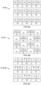
- FIG 5A illustrates absorption spectra of oxyhaemoglobine and deoxyhaemoglobine
- FIG 5B illustrates a measurement of reflected light "Lr" as function of time, and at different wavelengths (here: 760 nm and 850 nm which is also indicated in FIG 5A ).
- the system as described herein is configured to measure the reflected light "Lr" as function of time "T".
- the sensor device is configured to take periodic measurements of respective light intensity.
- the system e.g. sensor device and computing device
- the system is capable of measuring and/or processing at least one measurement per second, more preferably at least five measurements per second, most preferably at least ten measurements per second, e.g. up to one hundred measurements per second, or more.
- Providing relatively quick and/or many measurements may allow to adapt to changing conditions, such as eye movement. For example, each measurement may take less than ten milliseconds, less than five milliseconds, or even less than one millisecond.
- providing more measurements per second may allow to better monitor also physiological parameters characterized by a change or frequency.
- the variation of the measured signal may also be referred to as the AC signal, while the baseline or DC signal may be relatively static, at least more slowly varying than the AC signal.
- the DC signal may be determined as a moving average while AC signal may determine by subtracting the DC signal or using another average (e.g. less points).
- frequencies in the signal may be filtered to isolate a frequency range which may physically correspond to heart rate or other physiological parameter of interest, e.g. breathing; and/or isolate a more slowly changing DC signal.
- other or further filtering may be applied, e.g. isolating or compensating for changes in baseline which may be attributed to eye movement, breathing, head movement, et cetera.
- the sensor device 12 is configured to measure a light intensity of the reflected light "Lr" as function of time "T".
- the computing device 13 is configured to calculate a frequency "F" of a variation of the light intensity for determining a physiological parameter "Pf' indicating a heart rate of the user. For example, an elevated or lowered heart rate may be indicative of various physiological conditions, such as stress and/or physical strain.
- the computing device 13 is configured to calculate a variation of the light intensity for determining a physiological parameter "Pf' indicating a (cerebral) blood pressure.
- an amplitude "A" of the variation of the light intensity may be an indication of blood pulsation amplitude, which may be correlated with blood pressure.
- an AC component of the signal may be used as indication how much blood is still arriving at the retina, which may be affected by G-Force.
- overall (DC) variation of the light intensity may be used to derive physiological information, such as blood pressure.
- short time variations may be correlated with heart rate rhythm.
- long term variations may be correlated with changes in blood pressure, e.g. as a result of stress, exertion, et cetera.
- a shape of the signal may be used. For example, when the blood pressure is relatively high, this may be indicated by a flattening of the peak and/or low value, e.g. due to reaching a maximum stretchability of the blood vessel.
- the (varying) light intensity signal may be combined with a separate (timed) ECG signal, e.g. to compare the time of arrival.
- the arrival time may be relatively shorter than for a relatively low blood pressure.
- the monitoring system as described herein comprises or couples to a separate ECG sensor, e.g. measuring the heart rate at another part of the user's body (not via the retina).
- the system is configured to measure the reflected light "Lr" as function of wavelength ⁇ .
- reflected light may be spectrally resolved and/or filtered, to isolate or separately measure one, two, three, or more wavelengths in a visible or infrared region of interest.
- one or more sensor elements of the sensor device 12 comprises a respective spectral band filter to measure light at a specific wavelength.
- the wavelength of the light source 11 may be modulated.
- the wavelength of source light may be modulated between distinct wavelengths while measuring the respective intensity of reflected light.
- the measures wavelengths include one or more wavelengths that can be used to distinguish absorption in blood vessels of the retina versus other retinal tissue. In this way, various physiological parameters related to blood supply, or absence thereof, may be monitored.
- the sensor device 12 comprises an imaging device configured to generate an image of the user's retina "Ru".
- the computing device 13 is configured to process the image of the user's retina "Ru" to determine a position of at least one blood vessel in the retina (e.g. retinal artery), and to determine the physiological parameter "Pf' of the user based on the measured light "Lr" at the position of at least one blood vessel.
- the computing device 13 is configured to process the image of the user's retina "Ru” to determine a position of background retinal tissue without blood vessel and determine the physiological parameter "Pf' of the user based on the measured light "Lr" at the position of the background retinal tissue.
- the retinal tissue does not need to be imaged.
- the reflected light "Lr” can be combined or (non-imaged) light from the user's retina “Ru” can be collected and/or used to determine the physiological parameter "Pf'.
- the computing device 13 is configured to determine the physiological parameter "Pf' of the user based on a difference between the measured light "Lr” at the position of the at least one blood vessel and the measured light "Lr” at the position of the background retinal tissue. By distinguishing light originating from a blood vessel versus background retinal tissue, sensitivity can be improved. Alternatively, such distinction on the sensor side may not be necessary e.g. if the light exclusively or predominantly illuminates a blood vessel. For example, the HMD system may already be configured to track eye movement and adjust the light source 11 accordingly.
- the measurement device may be sufficiently sensitive to distinguish small variations even on top of a larger background signal.
- the sensor device 12 may comprise one or more of a single light detecting element, multiple light detecting elements (e.g. two detectors and/or a pixel array configured to measure multiple spectral features of the reflected light), a single imaging device, and/or multiple imaging devices (e.g. one for each wavelength).
- the computing device 13 comprises a neural network or machine learning algorithm (A.I.) to determine one or more physiological parameters "Pf' based on the reflected light "Lr".
- the neural network is trained to correlate measured light reflection with a value for one or more physiological parameters "Pf'.
- the one or more physiological parameters are measured independently and used as feedback in the learning.
- the neural network is trained for a specific user.
- the network may be able to distinguish the particular characteristics of the user's eye (blood vessels) and/or corresponding physiological condition.
- the neural network is provided with one or more images of the reflected light representing the retina and outputs an indication for at least one physiological parameters.
- the neural network is provided with multiple images at different instances of time and/or at different wavelengths. In this way, a more informed output may be calculated.
- the system comprises a feedback device (not shown) configured to output a feedback signal based on the determined physiological parameter "Pf".
- the feedback may be provided in one or more of a visual, audio, or haptic feedback signal.
- the feedback signal may alert the user or other personnel of measuring a nominal value or deviation from a nominal value.
- a visual signal indicating the physiological parameter "Pf' is provided via the display generator 14.
- an electric (or optical) signal may be provided, e.g. as feedback for other systems or devices.
- FIG 6A illustrates a ratio of light intensity measured at different wavelengths.
- the figure shows both the ratio RAC of the raw (alternating) signals L760/L850, and the ratio of the corresponding DC signals (moving average);
- FIG 3B illustrates a correlation between the ratio of light intensity and oxygenation level measured by an independent sensor.
- the sensor device 12 is configured to measure a respective light intensity (L850,L760) of the reflected light "Lr" at (at least) two distinct wavelengths ⁇ , e.g. here 760 nm and 850 nm, but this could of course also be measured at other or further suitable wavelengths.
- the computing device 13 is configured to determine a physiological parameter "Pf' including an indicative value of (cerebral) oxygenation based on the respective light intensity at the two distinct wavelengths ⁇ . This is also known as a retinal oxygenation measurement.
- the indicative value of oxygenation is based on a ratio and/or difference between the respective light intensity at two distinct wavelengths ⁇ .
- FIG 6A shows the ratio (L760 / L850) of signals such as shown in FIG 5B .
- the wavelengths include an anisosbestic wavelength where the absorption coefficient of oxyhaemoglobine and deoxyhaemoglobine are different. More preferably at least two anisosbestic wavelengths are used, most preferably having a different, e.g. opposite ratio. For example, at a first measured wavelength (e.g. 760 nm) the absorption of deoxyhaemoglobine may be larger than that of oxyhaemoglobine and at a second wavelength (e.g. 850 nm) it may be smaller.
- a first measured wavelength e.g. 760 nm
- a second wavelength e.g. 850 nm
- the measured one or more wavelengths include an isosbestic wavelength where the absorption coefficient of oxyhaemoglobine and deoxyhaemoglobine are the same, e.g. around 800 nm which is advantageously outside the visible spectrum.
- the measurement at an isosbestic wavelength may be advantageous as a reference and/or advantageous for measuring other physiological parameters, independent of oxygenation. For example, a single anisosbestic wavelength may be monitored to determine heart rate, blood pressure, et cetera.
Priority Applications (2)
| Application Number | Priority Date | Filing Date | Title |
|---|---|---|---|
| EP22197550.1A EP4342370A1 (de) | 2022-09-23 | 2022-09-23 | Kopfmontiertes überwachungssystem |
| PCT/NL2023/050494 WO2024063651A1 (en) | 2022-09-23 | 2023-09-22 | Head-mounted monitoring system |
Applications Claiming Priority (1)
| Application Number | Priority Date | Filing Date | Title |
|---|---|---|---|
| EP22197550.1A EP4342370A1 (de) | 2022-09-23 | 2022-09-23 | Kopfmontiertes überwachungssystem |
Publications (1)
| Publication Number | Publication Date |
|---|---|
| EP4342370A1 true EP4342370A1 (de) | 2024-03-27 |
Family
ID=83438331
Family Applications (1)
| Application Number | Title | Priority Date | Filing Date |
|---|---|---|---|
| EP22197550.1A Pending EP4342370A1 (de) | 2022-09-23 | 2022-09-23 | Kopfmontiertes überwachungssystem |
Country Status (2)
| Country | Link |
|---|---|
| EP (1) | EP4342370A1 (de) |
| WO (1) | WO2024063651A1 (de) |
Citations (4)
| Publication number | Priority date | Publication date | Assignee | Title |
|---|---|---|---|---|
| USH1039H (en) * | 1988-11-14 | 1992-04-07 | The United States Of America As Represented By The Secretary Of The Air Force | Intrusion-free physiological condition monitoring |
| WO2006086010A2 (en) * | 2004-08-11 | 2006-08-17 | University Of Florida Research Foundation, Inc. | Methods and devices for countering gravity induced loss of consciousness and novel pulse oximeter probes |
| WO2014155288A2 (en) * | 2013-03-25 | 2014-10-02 | Ecole Polytechnique Federale De Lausanne (Epfl) | Method and apparatus for head worn display with multiple exit pupils |
| US20160270656A1 (en) * | 2015-03-16 | 2016-09-22 | Magic Leap, Inc. | Methods and systems for diagnosing and treating health ailments |
-
2022
- 2022-09-23 EP EP22197550.1A patent/EP4342370A1/de active Pending
-
2023
- 2023-09-22 WO PCT/NL2023/050494 patent/WO2024063651A1/en unknown
Patent Citations (4)
| Publication number | Priority date | Publication date | Assignee | Title |
|---|---|---|---|---|
| USH1039H (en) * | 1988-11-14 | 1992-04-07 | The United States Of America As Represented By The Secretary Of The Air Force | Intrusion-free physiological condition monitoring |
| WO2006086010A2 (en) * | 2004-08-11 | 2006-08-17 | University Of Florida Research Foundation, Inc. | Methods and devices for countering gravity induced loss of consciousness and novel pulse oximeter probes |
| WO2014155288A2 (en) * | 2013-03-25 | 2014-10-02 | Ecole Polytechnique Federale De Lausanne (Epfl) | Method and apparatus for head worn display with multiple exit pupils |
| US20160270656A1 (en) * | 2015-03-16 | 2016-09-22 | Magic Leap, Inc. | Methods and systems for diagnosing and treating health ailments |
Also Published As
| Publication number | Publication date |
|---|---|
| WO2024063651A1 (en) | 2024-03-28 |
Similar Documents
| Publication | Publication Date | Title |
|---|---|---|
| US20220061660A1 (en) | Method for Determining at Least One Parameter of Two Eyes by Setting Data Rates and Optical Measuring Device | |
| KR102296369B1 (ko) | 도광 광학 소자를 통한 망막 이미징 기반 안구 추적기 | |
| US9606354B2 (en) | Heads-up display with integrated display and imaging system | |
| US11609425B2 (en) | Augmented reality glasses with auto coregistration of invisible field on visible reality | |
| US10684477B2 (en) | Near-eye display device and methods with coaxial eye imaging | |
| US9033502B2 (en) | Optical measuring device and method for capturing at least one parameter of at least one eye wherein an illumination characteristic is adjustable | |
| US20130194244A1 (en) | Methods and apparatuses of eye adaptation support | |
| US10314482B2 (en) | Eye alignment monitor and method | |
| JP2006516752A (ja) | 瞳孔の位置に対する眼鏡レンズの相対位置を調整する装置および方法 | |
| JP7018634B2 (ja) | 眼球運動測定装置及び眼球運動解析システム | |
| EP4342370A1 (de) | Kopfmontiertes überwachungssystem | |
| US9089286B2 (en) | Optical system for following ocular movements and associated support device | |
| WO2022196650A1 (ja) | 視線追跡システムおよび虚像表示装置 | |
| EP3292811B1 (de) | Vorrichtung zum screening von konvergenzinsuffizienz und zugehörige verfahren | |
| CN117043721A (zh) | 用于确定眼睛方向的眼睛配戴物 |
Legal Events
| Date | Code | Title | Description |
|---|---|---|---|
| PUAI | Public reference made under article 153(3) epc to a published international application that has entered the european phase |
Free format text: ORIGINAL CODE: 0009012 |
|
| STAA | Information on the status of an ep patent application or granted ep patent |
Free format text: STATUS: THE APPLICATION HAS BEEN PUBLISHED |
|
| AK | Designated contracting states |
Kind code of ref document: A1 Designated state(s): AL AT BE BG CH CY CZ DE DK EE ES FI FR GB GR HR HU IE IS IT LI LT LU LV MC MK MT NL NO PL PT RO RS SE SI SK SM TR |