EP3292811B1 - Vorrichtung zum screening von konvergenzinsuffizienz und zugehörige verfahren - Google Patents
Vorrichtung zum screening von konvergenzinsuffizienz und zugehörige verfahren Download PDFInfo
- Publication number
- EP3292811B1 EP3292811B1 EP17190232.3A EP17190232A EP3292811B1 EP 3292811 B1 EP3292811 B1 EP 3292811B1 EP 17190232 A EP17190232 A EP 17190232A EP 3292811 B1 EP3292811 B1 EP 3292811B1
- Authority
- EP
- European Patent Office
- Prior art keywords
- video frames
- eye
- visual stimulus
- movement
- processor
- Prior art date
- Legal status (The legal status is an assumption and is not a legal conclusion. Google has not performed a legal analysis and makes no representation as to the accuracy of the status listed.)
- Not-in-force
Links
Images












Classifications
-
- A—HUMAN NECESSITIES
- A61—MEDICAL OR VETERINARY SCIENCE; HYGIENE
- A61B—DIAGNOSIS; SURGERY; IDENTIFICATION
- A61B3/00—Apparatus for testing the eyes; Instruments for examining the eyes
- A61B3/10—Objective types, i.e. instruments for examining the eyes independent of the patients' perceptions or reactions
- A61B3/113—Objective types, i.e. instruments for examining the eyes independent of the patients' perceptions or reactions for determining or recording eye movement
-
- A—HUMAN NECESSITIES
- A61—MEDICAL OR VETERINARY SCIENCE; HYGIENE
- A61B—DIAGNOSIS; SURGERY; IDENTIFICATION
- A61B3/00—Apparatus for testing the eyes; Instruments for examining the eyes
- A61B3/0016—Operational features thereof
- A61B3/0041—Operational features thereof characterised by display arrangements
-
- A—HUMAN NECESSITIES
- A61—MEDICAL OR VETERINARY SCIENCE; HYGIENE
- A61B—DIAGNOSIS; SURGERY; IDENTIFICATION
- A61B3/00—Apparatus for testing the eyes; Instruments for examining the eyes
- A61B3/0016—Operational features thereof
- A61B3/0041—Operational features thereof characterised by display arrangements
- A61B3/0058—Operational features thereof characterised by display arrangements for multiple images
-
- A—HUMAN NECESSITIES
- A61—MEDICAL OR VETERINARY SCIENCE; HYGIENE
- A61B—DIAGNOSIS; SURGERY; IDENTIFICATION
- A61B3/00—Apparatus for testing the eyes; Instruments for examining the eyes
- A61B3/0091—Fixation targets for viewing direction
-
- A—HUMAN NECESSITIES
- A61—MEDICAL OR VETERINARY SCIENCE; HYGIENE
- A61B—DIAGNOSIS; SURGERY; IDENTIFICATION
- A61B3/00—Apparatus for testing the eyes; Instruments for examining the eyes
- A61B3/02—Subjective types, i.e. testing apparatus requiring the active assistance of the patient
- A61B3/08—Subjective types, i.e. testing apparatus requiring the active assistance of the patient for testing binocular or stereoscopic vision, e.g. strabismus
-
- A—HUMAN NECESSITIES
- A61—MEDICAL OR VETERINARY SCIENCE; HYGIENE
- A61B—DIAGNOSIS; SURGERY; IDENTIFICATION
- A61B3/00—Apparatus for testing the eyes; Instruments for examining the eyes
- A61B3/02—Subjective types, i.e. testing apparatus requiring the active assistance of the patient
- A61B3/09—Subjective types, i.e. testing apparatus requiring the active assistance of the patient for testing accommodation
-
- A—HUMAN NECESSITIES
- A61—MEDICAL OR VETERINARY SCIENCE; HYGIENE
- A61B—DIAGNOSIS; SURGERY; IDENTIFICATION
- A61B3/00—Apparatus for testing the eyes; Instruments for examining the eyes
- A61B3/10—Objective types, i.e. instruments for examining the eyes independent of the patients' perceptions or reactions
- A61B3/11—Objective types, i.e. instruments for examining the eyes independent of the patients' perceptions or reactions for measuring interpupillary distance or diameter of pupils
- A61B3/111—Objective types, i.e. instruments for examining the eyes independent of the patients' perceptions or reactions for measuring interpupillary distance or diameter of pupils for measuring interpupillary distance
-
- A—HUMAN NECESSITIES
- A61—MEDICAL OR VETERINARY SCIENCE; HYGIENE
- A61B—DIAGNOSIS; SURGERY; IDENTIFICATION
- A61B3/00—Apparatus for testing the eyes; Instruments for examining the eyes
- A61B3/10—Objective types, i.e. instruments for examining the eyes independent of the patients' perceptions or reactions
- A61B3/14—Arrangements specially adapted for eye photography
-
- A—HUMAN NECESSITIES
- A61—MEDICAL OR VETERINARY SCIENCE; HYGIENE
- A61B—DIAGNOSIS; SURGERY; IDENTIFICATION
- A61B3/00—Apparatus for testing the eyes; Instruments for examining the eyes
- A61B3/10—Objective types, i.e. instruments for examining the eyes independent of the patients' perceptions or reactions
- A61B3/14—Arrangements specially adapted for eye photography
- A61B3/145—Arrangements specially adapted for eye photography by video means
-
- A—HUMAN NECESSITIES
- A61—MEDICAL OR VETERINARY SCIENCE; HYGIENE
- A61B—DIAGNOSIS; SURGERY; IDENTIFICATION
- A61B3/00—Apparatus for testing the eyes; Instruments for examining the eyes
- A61B3/18—Arrangement of plural eye-testing or -examining apparatus
-
- A—HUMAN NECESSITIES
- A61—MEDICAL OR VETERINARY SCIENCE; HYGIENE
- A61B—DIAGNOSIS; SURGERY; IDENTIFICATION
- A61B5/00—Measuring for diagnostic purposes; Identification of persons
- A61B5/103—Measuring devices for testing the shape, pattern, colour, size or movement of the body or parts thereof, for diagnostic purposes
- A61B5/11—Measuring movement of the entire body or parts thereof, e.g. head or hand tremor or mobility of a limb
- A61B5/1103—Detecting muscular movement of the eye, e.g. eyelid movement
-
- G—PHYSICS
- G06—COMPUTING OR CALCULATING; COUNTING
- G06T—IMAGE DATA PROCESSING OR GENERATION, IN GENERAL
- G06T11/00—Two-dimensional [2D] image generation
- G06T11/20—Drawing from basic elements
- G06T11/26—Drawing of charts or graphs
-
- G—PHYSICS
- G06—COMPUTING OR CALCULATING; COUNTING
- G06T—IMAGE DATA PROCESSING OR GENERATION, IN GENERAL
- G06T11/00—Two-dimensional [2D] image generation
- G06T11/60—Creating or editing images; Combining images with text
-
- G—PHYSICS
- G06—COMPUTING OR CALCULATING; COUNTING
- G06T—IMAGE DATA PROCESSING OR GENERATION, IN GENERAL
- G06T7/00—Image analysis
- G06T7/0002—Inspection of images, e.g. flaw detection
- G06T7/0012—Biomedical image inspection
-
- G—PHYSICS
- G06—COMPUTING OR CALCULATING; COUNTING
- G06T—IMAGE DATA PROCESSING OR GENERATION, IN GENERAL
- G06T7/00—Image analysis
- G06T7/0002—Inspection of images, e.g. flaw detection
- G06T7/0012—Biomedical image inspection
- G06T7/0014—Biomedical image inspection using an image reference approach
- G06T7/0016—Biomedical image inspection using an image reference approach involving temporal comparison
-
- G—PHYSICS
- G06—COMPUTING OR CALCULATING; COUNTING
- G06T—IMAGE DATA PROCESSING OR GENERATION, IN GENERAL
- G06T7/00—Image analysis
- G06T7/20—Analysis of motion
- G06T7/246—Analysis of motion using feature-based methods, e.g. the tracking of corners or segments
-
- G—PHYSICS
- G06—COMPUTING OR CALCULATING; COUNTING
- G06T—IMAGE DATA PROCESSING OR GENERATION, IN GENERAL
- G06T7/00—Image analysis
- G06T7/20—Analysis of motion
- G06T7/292—Multi-camera tracking
-
- G—PHYSICS
- G06—COMPUTING OR CALCULATING; COUNTING
- G06T—IMAGE DATA PROCESSING OR GENERATION, IN GENERAL
- G06T7/00—Image analysis
- G06T7/70—Determining position or orientation of objects or cameras
- G06T7/73—Determining position or orientation of objects or cameras using feature-based methods
- G06T7/74—Determining position or orientation of objects or cameras using feature-based methods involving reference images or patches
-
- A—HUMAN NECESSITIES
- A61—MEDICAL OR VETERINARY SCIENCE; HYGIENE
- A61B—DIAGNOSIS; SURGERY; IDENTIFICATION
- A61B2560/00—Constructional details of operational features of apparatus; Accessories for medical measuring apparatus
- A61B2560/04—Constructional details of apparatus
- A61B2560/0475—Special features of memory means, e.g. removable memory cards
-
- A—HUMAN NECESSITIES
- A61—MEDICAL OR VETERINARY SCIENCE; HYGIENE
- A61B—DIAGNOSIS; SURGERY; IDENTIFICATION
- A61B3/00—Apparatus for testing the eyes; Instruments for examining the eyes
- A61B3/0016—Operational features thereof
- A61B3/0025—Operational features thereof characterised by electronic signal processing, e.g. eye models
-
- G—PHYSICS
- G06—COMPUTING OR CALCULATING; COUNTING
- G06T—IMAGE DATA PROCESSING OR GENERATION, IN GENERAL
- G06T2207/00—Indexing scheme for image analysis or image enhancement
- G06T2207/10—Image acquisition modality
- G06T2207/10016—Video; Image sequence
-
- G—PHYSICS
- G06—COMPUTING OR CALCULATING; COUNTING
- G06T—IMAGE DATA PROCESSING OR GENERATION, IN GENERAL
- G06T2207/00—Indexing scheme for image analysis or image enhancement
- G06T2207/10—Image acquisition modality
- G06T2207/10048—Infrared image
-
- G—PHYSICS
- G06—COMPUTING OR CALCULATING; COUNTING
- G06T—IMAGE DATA PROCESSING OR GENERATION, IN GENERAL
- G06T2207/00—Indexing scheme for image analysis or image enhancement
- G06T2207/20—Special algorithmic details
- G06T2207/20024—Filtering details
-
- G—PHYSICS
- G06—COMPUTING OR CALCULATING; COUNTING
- G06T—IMAGE DATA PROCESSING OR GENERATION, IN GENERAL
- G06T2207/00—Indexing scheme for image analysis or image enhancement
- G06T2207/30—Subject of image; Context of image processing
- G06T2207/30004—Biomedical image processing
- G06T2207/30041—Eye; Retina; Ophthalmic
Definitions
- This present application relates to a medical device, and more particularly, to a device for screening visual issues in a patient.
- Convergence Insufficiency occurs when a subject's brain fails to coordinate images from both eyes while trying to focus on a nearby object. When a subject reads or looks at a close object, the subject's eyes must both turn inwardly (convergence) to focus. In studies that used standardized definitions of Convergence Insufficiency, investigators have reported a prevalence of 4.2% to 6% in school and clinic settings. Convergence Insufficiency is a common binocular vision disorder that is often associated with a variety of symptoms, including eyestrain, headaches, blurred vision, diplopia (double vision), sleepiness, difficulty concentrating, movement of print while reading, and loss of comprehension after short periods of reading or performing close activities.
- CI can cause difficulty with reading. This may make parents or teachers suspect that a child has a learning disability, instead of an eye disorder. In the past, CI disorder has often gone undetected because CI testing is not included in (1) a pediatrician's eye test; (2) school screenings; or (3) basic eye exams. A person can pass the 20/20 eye chart test and still have CI.
- a device for screening a person for CI.
- the device may include a binocular viewer comprising a first eyepiece to receive a first eye of the person, a second eyepiece to receive a second eye of the person, a first image sensor adjacent the first eyepiece, and a second image sensor adjacent the second eyepiece, a display adjacent the binocular viewer, and a processor and associated memory cooperating with the display.
- the processor may be configured to record, with the first image sensor, movement of the first eye, record, with the second image sensor, movement of the second eye, and display on the display a first visual stimulus and a second visual stimulus.
- the processor may be configured to cause, in alternating fashion, convergent movement and divergent movement in the first visual stimulus and the second visual stimulus along a visual stimulus path, determine respective centroid positions of the second eye and the first eye during the convergent and divergent movement of the first visual stimulus and the second visual stimulus, and calculate an interpupillary distance (IPD), and compare the IPD with the visual stimulus path to obtain a dynamic IPD, the dynamic IPD serving as an indicator for whether the person has CI.
- IPD interpupillary distance
- a duration of each of the convergent movement and the divergent movement is 80-100 seconds.
- the device may also include a first infrared (IR) source configured to irradiate the first eye and a second IR illuminator configured to irradiate second eye, and the processor and memory may be configured to generate a first plurality of video frames showing movement of the first eye, and generate a second plurality of video frames showing movement of the second eye.
- IR infrared
- the processor and memory may be configured to identify second blink pixels comprising second eye blinks in the second plurality of video frames, and form a third plurality of video frames by removing the second blink pixels from the second plurality of video frames.
- the processor and memory may be configured to identify first blink pixels comprising first eye blinks in the first plurality of video frames, and form a fourth plurality of video frames by removing the first blink pixels from the first plurality of video frames.
- the processor and memory may be configured to generate the first plurality of video frames by performing at least filtering each of the first plurality of video frames using a pixel intensity threshold to form a third plurality of video frames, each of the third plurality of video frames comprising a black background in combination with a white background, a first eye image, the third plurality of video frames comprising an N number of video frames, and filtering each of the second plurality of video frames using the pixel intensity threshold to form a fourth plurality of video frames, each of the fourth plurality of video frames comprising a black background in combination with a white background, a second eye image, the fourth plurality of video frames comprising an M number of video frames.
- the processor and memory may be configured to generate the first plurality of video frames by performing at least determining, for each of the third plurality of video frames, x and y coordinates for a first eye pupil centroid, and generating a first plurality of x coordinate datasets.
- An ith x coordinate dataset represents a location of an ith second pupil centroid, and i is greater than or equal to 1 and less than or equal to N.
- the processor and memory may be configured to generate the first plurality of video frames by performing at least determining, for each of the fourth plurality of video frames, x and y coordinates for a second eye pupil centroid, and generating a second plurality of x coordinate datasets.
- a jth x coordinate dataset represents a location of a jth first pupilar centroid, and j is greater than or equal to 1 and less than or equal to M.
- the processor and memory may be configured to graphically display a first curve comprising N x coordinate datasets versus time, and graphically display a second curve comprising M x coordinate datasets versus time.
- the processor and memory may be configured to form a third curve comprising each of the hth dynamic IPD versus time.
- the processor and memory may be configured to identify a first substantially linear portion of the third curve, the first substantially linear portion comprising a positive slope, identify a second substantially linear portion of the third curve, the second substantially linear portion comprising a negative slope, generate a graphical plot of the visual stimulus path, the graphical plot comprising a first linear portion comprising a positive slope and a second linear portion comprising a negative slope, overlap the third curve onto the graphical plot of the visual stimulus path, and adjust the third curve to fit onto graphical plot of the visual stimulus path.
- the processor and memory may be configured to compare the dynamic IPD with the visual stimulus path by performing at least optimizing a graph of dynamic IPDs with at least one parameter, and merging the optimized graph of dynamic IPDs with the visual stimulus path.
- the method may include recording, with a first image sensor, movement of a first eye of the person, recording, with a second image sensor, movement of a second eye of the person, and displaying on a display a first visual stimulus and a second visual stimulus.
- the method may include causing, in alternating fashion, convergent movement and divergent movement in the first visual stimulus and the second visual stimulus along a visual stimulus path, determining respective centroid positions of the second eye and the first eye during the convergent and divergent movement of the first visual stimulus and the second visual stimulus, and using a processor and memory associated with the display, and the first and second image sensors for calculating an interpupillary distance (IPD), and comparing the IPD with the visual stimulus path to obtain a dynamic IPD, the dynamic IPD serving as an indicator for whether the person has CI.
- IPD interpupillary distance
- Another aspect is directed to a device for screening a person for CI with a binocular viewer comprising a first eyepiece to receive a first eye of the person, a second eyepiece to receive a second eye of the person, a first image sensor adjacent the first eyepiece, and a second image sensor adjacent the second eyepiece.
- the device may include a display adjacent the binocular viewer, and a processor and associated memory cooperating with the display.
- the processor may be configured to record, with the first image sensor, movement of the first eye, record, with the second image sensor, movement of the second eye, and display on the display a first visual stimulus and a second visual stimulus.
- the processor may be configured to cause, in alternating fashion, convergent movement and divergent movement in the first visual stimulus and the second visual stimulus along a visual stimulus path, determine respective centroid positions of the second eye and the first eye during the convergent and divergent movement of the first visual stimulus and the second visual stimulus, and calculate an interpupillary distance (IPD), and compare the IPD with the visual stimulus path to obtain a dynamic IPD, the dynamic IPD serving as an indicator for whether the person has CI.
- IPD interpupillary distance
- Another aspect is directed to a non-transitory computer-readable medium having computer-executable instructions for causing a computing device comprising a processor and associated memory to perform a method for screening a person for CI.
- the method may include recording, with a first image sensor, movement of a first eye of the person, recording, with a second image sensor, movement of a second eye of the person, and displaying on a display a first visual stimulus and a second visual stimulus.
- the method may include causing, in alternating fashion, convergent movement and divergent movement in the first visual stimulus and the second visual stimulus along a visual stimulus path, determining respective centroid positions of the second eye and the first eye during the convergent and divergent movement of the first visual stimulus and the second visual stimulus, and calculating an IPD, and comparing the IPD with the visual stimulus path to obtain a dynamic IPD, the dynamic IPD serving as an indicator for whether the person has CI.
- Certain embodiments of Applicant's disclosure recite a method to screen a person for CI.
- the steps of the method comprise providing a screening apparatus, positioning a patient in front of the screening apparatus so that the patient looks into the apparatus, displaying visual stimuli convergently and divergently to generate a visual stimulus path, determining respective centroid positions of each eye, calculating an interpupillary distance (IPD) between the eyes, and comparing the IPD with the visual stimulus path to obtain a dynamic IPD, which is an indicator for whether the patient has CI.
- IPD interpupillary distance
- the screening apparatus with a binocular viewer and a housing attached to the binocular viewer.
- the binocular viewer comprises two eyepieces, two mirrors, and two infrared (IR) illuminators; and the housing comprises two video cameras and a visual display device.
- the visual display is movable.
- the binocular viewer comprises two eyepieces and two mirrors.
- the binocular viewer does not contain any (IR) illuminators.
- the binocular viewer comprises two eyepieces, four mirrors, and two infrared (IR) illuminators.
- the binocular viewer comprises two eyepieces and four mirrors, without the IR illuminators.
- the visual display is movable.
- Applicant's apparatus and method provide a mechanism to evaluate the ability of the subject's brain to merge the two perceived objects into a single 2-D or 3-D image.
- Applicant's assembly for objectively screening subjects for Convergence Insufficiency comprises a binocular viewer 110, a housing 120 attached to binocular viewer 110, and a controller 130.
- a subject 102 is positioned in front of binocular viewer 110.
- the subject 102 positions his or her eyes 202A and 202B in front of eyepieces 126 and 128, respectively.
- the subject 102 places both hands on a surface supporting housing 120 to eliminate head movement during the examination. Further, the distance between the two eyepieces 126 and 128 can be adjusted to match a distance between the test subject's eyes 202A and 202B.
- a virtual reality (VR) mask / headset fits over binocular viewer 110. Applicant has found that the VR mask faceplate can position the test subject's head into the best position for testing and reduce movement.
- VR virtual reality
- Applicant's apparatus comprises two (2) front surface mirrors and two (2) cold mirrors disposed in housing 120 and a single visual display device. In other embodiments, Applicant's apparatus comprises two (2) front surface mirrors and two (2) cold mirrors disposed in housing 120 and a single visual display device, wherein the visual display device is moveable within the housing.
- Applicant's apparatus comprises two (2) front surface mirrors and two (2) cold mirrors disposed in housing 120, a single visual display device, and two (2) infrared emitters disposed in housing 120. In still other embodiments, Applicant's apparatus comprises two (2) different front surface mirrors and two (2) cold mirrors disposed in housing 120, a single visual display device, and two (2) infrared emitters disposed in housing 120, wherein the visual display device is moveable within the housing.
- Applicant's apparatus comprises two (2) cold mirrors disposed in housing 120 and two different visual display devices. In other embodiments, Applicant's apparatus comprises two (2) front surface (or cold) different mirrors disposed in housing 120 and two different visual display devices, wherein one or more of the visual display devices is moveable within the housing. In further embodiments, Applicant's apparatus comprises two (2) different front surface (or cold) mirrors disposed in housing 120, two (2) different visual display devices disposed in housing 120, and two (2) infrared emitters disposed in housing 120.
- Applicant's apparatus comprises two (2) different front surface (or cold) mirrors disposed in housing 120, two (2) different visual display devices disposed in housing 120, and two (2) infrared emitters disposed in housing 120, wherein one or more of the visual display devices is moveable within housing 120.
- housing 120 comprises a camera 240, a camera 250, and a visual display 230 ( FIG. 2 ).
- a controller 130 is in communication with both cameras 240 and 250, and the visual display 230.
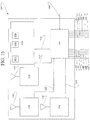
- controller 1500 comprises processor 1510, memory 1520 interconnected with processor 1510 via communication link 1525, optional Bluetooth module 1530 interconnected with processor 1510 via communication link 1535, optional RFID module 1540 interconnected with processor 1510 via communication link 1545, and optional "WI-FI" module 1550 interconnected with processor 1510 via communication link 1555.
- microcode 1522, instructions 1524, and database 1526 are encoded in memory 1520.
- memory 1520 comprises non-volatile memory.
- memory 1520 comprises battery backed up RAM, a magnetic hard disk assembly, an optical disk assembly, and/or electronic memory.
- electroactive memory Applicants mean a PROM, EPROM, EEPROM, SMARTMEDIA, FLASHMEDIA, and the like.
- Processor 1510 uses microcode 1522 to operate controller 1500.
- Processor 1510 uses microcode 1522, instructions 1524, and database 1526, to operate Applicant's assembly 100, Bluetooth module 1530, RFID module 1540, and WI-FI module 1550.
- processor 1510, memory 1520, optional Bluetooth module 1530, optional RFID module 1540, and optional "WI-FI” module 1550 are integrated into an application specific integrated circuit, i.e. an "ASIC.”
- the binocular viewer 110 comprises two eyepieces 126 and 128, two infrared (IR) emitters 260 and 270, and four mirrors 121, 123, 125, and 127.
- the eyepieces 126 and 128 are disposed in surface 110a of binocular viewer 110.
- Each eye sees a different, moveable stimulus on display 230.
- the stimulus can be white shown on black background. In other embodiments, the stimulus can be black shown on white background.
- mirrors 123 and 125 are cold mirrors, which allow light to go through on one side but is reflective on the other side, such as sides 123a and 125a are reflective ( FIG. 2A , these sides facing subject's eyes); whereas mirrors 121 and 127 are surface mirrors, which reflect normally on one side and the other side is non-reflective to avoid extra light issue. For example, sides 121a and 127a ( FIG. 2a ) of the surface mirrors reflect normally. Further, the reflective side of a cold mirror can block about 90% of visible light, which has a spectrum up to about 650 nanometers. As described herein, "about” is used to describe a plus or minus 10% difference in any measurements.
- the non-reflective sides 123b and 125b ( FIG. 2A ) of mirrors 123 and 125 allow cameras 240 and 250 to be positioned behind mirrors without causing obstruction or distraction to testing subjects because they are looking at the reflective sides 123a and 125a of the mirrors during the test and cannot see the cameras.
- an IR filter 150 FIG. 2B
- another IR filter 152 FIG. 2B
- the IR filters block light of wavelengths up to about 700 nanometers and they assist in preventing the light from leaking back into the cameras 240 and 250, which will cause blur or glare.
- a first eye 202A of a test subject 102 looks through the eyepiece 126 to observe moveable visual stimulus 236 shown on visual display 230.
- a sight path for first eye 202A passes through eyepiece 126 onto mirror 123, is redirected by reflective surface 123a onto mirror 121, is redirected by reflective surface 121a onto display 230.
- a second eye 202B of a test subject 102 looks through the eyepiece 128 to observe moveable visual stimulus 234 shown on visual display 230.
- a sight path for second eye 202A passes through eyepiece 128 onto mirror 125, is redirected by reflective surface 125a onto mirror 127, is redirected by reflective surface 127a onto display 230.
- Mirror 121 and surface 110a define a dihedral angle ⁇ a .
- Mirror 127 and surface 110a define a dihedral angle ⁇ b .
- angles ⁇ a and ⁇ b are about 135°.
- the dihedral angle between mirrors 123 and 125 is a right angle, i.e., the dihedral angle is about 90°.
- Mirror 123 is substantially parallel to mirror 121, with a reflective side 123a having a facing relationship with the reflective side 121a of mirror 121.
- Mirror 125 is substantially parallel to mirror 127 with reflective side 125a having a facing relationship with reflective side 127a of mirror 127.
- infrared (IR) emitter 270 is disposed adjacent eyepiece 126, and between mirrors 121 and 123.
- the infrared emitter 260 is disposed adjacent eyepiece 128, and between the mirrors 125 and 127.
- infrared radiation IR is invisible to human eyes, and comprises wavelengths longer than those of visible light, extending from the nominal red edge of the visible spectrum at 700 nanometers (frequency 430 THz) to 1 mm (300 GHz).
- the IR emitters 260 and 270 operate at a wavelength of 940 nanometers, which eliminates any distraction to a testing subject.
- Applicant has found that illuminating the eyes with infrared radiation eliminates unwanted artifacts in an eye image.
- the most distinctive feature in a recorded eye image is the contour of the pupil rather than limbus. Both the sclera and the iris strongly reflect infrared light, while only the sclera reflects visible light.
- Applicant has further found that tracking the sharp contour of the pupil instead of the iris gives more reproducible results because the small size of the pupil makes it less likely to be occluded by an eyelid.
- Binocular viewer 110 and housing 120 are designed to block visible light. Therefore, infrared eye tracking can be employed without interference from visible light.
- housing 120 is attached to binocular viewer 110, and comprises video camera 240 which is in communication with controller 130 via communication link 242, video camera 250 which is in communication with controller 130 via communication link 252, and visual display 230 which is in communication with controller 130 via communication link 232.
- Video camera 240 transmits eye movement data in digital video frame to the controller 130 via communication link 242.
- digital video frame data is transferred by video camera 240 to controller 130 in a digital bit stream.
- digital video frame data is transferred by video camera 240 to controller 130 as a digitized analog signal.
- Video camera 250 transmits eye movement data in digital video frame to the controller 130 via communication link 252.
- digital video frame data is transferred by video camera 250 to controller 130 in a digital bit stream.
- digital video frame data is transferred by video camera 250 to controller 130 as a digitized analog signal.
- the cameras 240 and 250 operate on fixed focus lenses, which are adjustable. In other embodiments, cameras 240 and 250 operate on auto focus lenses. In yet other embodiments, cameras 240 and 250 operate on telocentric lenses. In still other embodiments, cameras 240 and 250 operate on extended depth-of-field lenses.
- mirror 125 is disposed between video camera 240 and eyepiece 128.
- Mirror 125 and IR filter 150 are used to block the infrared radiation from bouncing back and interfering with the cameras.
- Infrared emitter 260 shines infrared light onto eye 202B, and video camera 240 is able to record the movement of eye 202B because of that infrared illumination.
- mirror 123 is disposed between video camera 250 and eyepiece 128.
- Mirror 123 and IR filter 152 are used to block the infrared radiation from bouncing back and interfering with the cameras.
- Infrared emitter 270 shines infrared light onto eye 202A, and video camera 250 is able to record the movement of eye 202A because of that infrared illumination.
- controller 130 causes the displayed visual stimuli 234 and 236 to move convergently and divergently in an alternate manner using a preprogrammed visual stimulus path.
- visual stimuli 234 and 236 are initially substantially merged on the visual display device. Even though visual stimuli 234 and 236 are not actually merged on the display device, the subject perceives only a single image because the subject's brain has formed a single image from the two differing right eye image and left eye image. In other embodiments, visual stimuli 234 and 236 can start unconverged and move slowly into convergence.
- the visual stimuli then move divergently, i.e. away from each other, in accord with curve 610 until a maximum separation is reached at point 630.
- the subject's brain is unable to maintain a single image, and the subject perceives two different images.
- visual stimuli 234 and 236 move convergently in accord with curve 620.
- the subject's brain can once again form a single perceived image.
- the divergent movement of the visual stimuli, followed by convergent movement of those visual stimuli takes about 90 seconds.
- the beginning separation between visual stimuli 234 and 236 varies from about 120 to about 150 mm, and preferably at about 140 mm.
- the maximum separation between visual stimuli 234 and 236 at point 630 ( FIG. 6A ) varies from about 250 to about 310 mm, and preferably at about 300 mm.
- the size of the stimuli 234 and 236 can be increased or decreased from one examination to another examination. Further, the brightness and the coloration of the stimuli 234 and 236 vary from one examination to another examination.
- the visual stimuli are separated by about 125 mm for about 5 seconds.
- the stimuli are instantly brought closer, i.e. to a separation of about 40 mm.
- the stimuli begin to separate, i.e. diverge, at a speed of about 1 to 3 mm/second, with the preferred speed of about 2 mm/second as shown by linear curve portion 610 having a positive slope.
- the divergence/convergence process repeats two or more times to generate multiple sets of video frames of eye movement to determine the reproducibility of Applicant's apparatus and method.
- visual display device 230 can be moved backwardly / forwardly. In certain embodiments, one or more iterations of Applicant's method summarized hereinabove are performed with visual display device 230 at a first distance from eyepieces 126 and 128. The visual display device is then repositioned at a second distance from eyepieces 126 and 128, and Applicant's procedure is repeated. In certain embodiments, the second distance is less than the first distance. In other embodiments, the second distance is greater than the first distance.
- visual display device 230 can be move forwardly and/or backwardly within housing 120.
- Apparatus 205 comprises the elements of apparatus 200, and further comprises locomotion assembly 280a attached to a first end of visual display device 230.
- Locomotion assembly 280a is interconnected to controller 130 by communication link 284.
- Locomotion tracks 295a are positioned such that moveable wheels disposed on locomotion assembly 280a can be disposed on locomotion tracks 295a.
- Apparatus 205 further comprises locomotion assembly 280b attached to a second end of visual display device 230.
- Locomotion assembly 280b is interconnected to controller 130 by communication link 282.
- Locomotion tracks 295b are positioned such that moveable wheels disposed on locomotion assembly 280b can be disposed on locomotion tracks 295b.
- Applicant's apparatus comprises two mirror and two visual display devices.
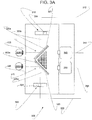
- apparatus 300 comprises two mirrors and two visual display devices.
- Apparatus 300 comprises a first mirror 323 comprising reflective surface 323a.
- Mirror 323 is disposed between eyepiece 126 and video camera 250.
- Sight path 305a originates at eyepiece 126, and includes reflective surface 323a, and visual display device 324.
- Display device 320 is interconnected to controller 130 via communication link 322.
- Apparatus 300 further comprises a second mirror 325 comprising reflective surface 325a.
- Mirror 325 is disposed between eyepiece 128 and video camera 240.
- Sight path 305b originates at eyepiece 128, and includes reflective surface 325a, and visual display device 314.
- Display device 310 is interconnected to controller 130 via communication link 312.
- apparatus 305 includes the elements of apparatus 300 ( FIG. 3A ) and further includes a first locomotion assembly 280c attached to a first end of visual display device 310.
- Locomotion assembly 280c is interconnected to controller 130 by communication link 315.
- Locomotion tracks 318 are positioned such that moveable wheels disposed on locomotion assembly 280c can be disposed on locomotion tracks 318.
- Apparatus 305 further comprises locomotion assembly 280d attached to a second end of visual display device 310.
- Locomotion assembly 280d is interconnected to controller 130 by communication link 313.
- Locomotion tracks 316 are positioned such that moveable wheels disposed on locomotion assembly 280d can be disposed on locomotion tracks 316.
- apparatus 305 comprises a third locomotion assembly 280e attached to a first end of visual display device 320, which is interconnected to controller 130 via communication link 322.
- Locomotion assembly 280e is interconnected to controller 130 by communication link 328.
- Locomotion tracks 319 are positioned such that moveable wheels disposed on locomotion assembly 280e can be disposed on locomotion tracks 319.
- a fourth locomotion assembly 280f attached to a second end of visual display device 320.
- Locomotion assembly 280f is interconnected to controller 130 by communication link.
- Locomotion tracks 317 are positioned such that moveable wheels disposed on locomotion assembly 280f can be disposed on locomotion tracks 317.
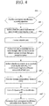
- FIG. 4 summarizes the steps of Applicant's method using Applicant's apparatus.
- the method provides an apparatus configured to screen subjects for convergence insufficiency.
- the method in step 410 provides apparatus 200 ( FIG. 2A ).
- the method in step 410 provides apparatus 205 ( FIG. 2B ).
- the method in step 410 provides apparatus 300 ( FIG. 3A ).
- the method in step 410 provides apparatus 305 ( FIG. 3B ).
- the method selects a form for a first visual stimulus. Further in step 420, the method selects a form for a second visual stimulus.
- the form selected for the first visual stimulus is identical to the form selected for the second visual stimulus.
- FIG. 6B shows a first visual stimulus and a second visual stimulus, wherein the first visual stimulus comprises the same form as the second visual stimulus.
- the form selected for a first visual stimulus differs from the form selected for a second visual stimulus.
- step 430 the method creates a stimulus path.
- an illustrated stimulus path is depicted in FIG. 6A .
- the size, the brightness, the beginning distance, and the moving speed of the two stimuli are determined in step 430.
- a testing subject 102 positions his or her eyes to look into eyepieces 126 and 128 disposed in binocular viewer 110.
- the method initiates visual stimulus movement on one or more attached visual display devices.
- the method synchronously begins recording eye movement of both eyes.
- a controller attached comprising a portion of the screening apparatus of step 410 performs step 430.
- a controller attached to the screening apparatus wirelessly receives an instruction to perform step 430.
- recorded video frames of the eye movements of eye 202A and eye 202B are stored in a non-transitory computer readable medium 1520 ( FIG. 15 ) by a processor 1510 ( FIG. 15 ) disposed in controller 130.
- computer readable medium 1520 comprises a magnetic storage medium, an optical storage medium, or an electronic storage medium.
- Applicant means a PROM, EPROM, EEPROM, Flash PROM, compactflash, smartmedia, and the like.
- the data calculation in steps 460, 470, and 480 can be performed after the examination. In other embodiments, the data calculation in steps 460, 470, and 480 can be performed in real time during the examination. In yet other embodiments, the data calculation in steps 460, 470, and 480 can be performed in slightly delayed real time during the examination.
- the method determines an interpupillary distance (IPD). IPD is the distance between the centers of the pupils of the two eyes.
- step 460 is performed by controller 1500 using processor 1510, and microcode 1522, and instructions 1524. In certain embodiments, controller 1500 wirelessly receives an instruction to perform step 460.
- the method graphically curve fits a plot of IPD versus time.
- the method converts the IPDs in pixel numbers ( FIG.10 ) to x coordinates in millimeters (mm).
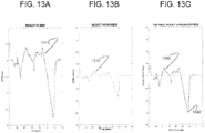
- a curve 1110 is a display of IPDs in mm versus time in seconds.
- a substantially linear portion 1120 of the curve 1110 comprising a positive slope and another substantially linear portion 1130 of the curve 1110 comprising a negative slope are identified.
- random sample consensus an iterative method to estimate parameters of a mathematical model from a set of observed data which contains errors and/or outliers, is used to remove errors and/or outliers and optimize the curve 1110.
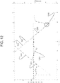
- an optimal curve 1210 of dynamic IPDs is generated by further adjusting the scale of the y-axis in mm.
- the optimal curve 1210 is overlapped with the visual stimulus path 640.
- a substantially linear portion 1220 comprising a positive slope of the curve 1210 overlays with the positive slope 610 of the visual stimulus path 640 and another substantially linear portion 1230 comprising a negative slope of the curve 1210 overlays with the negative slope 620 of the visual stimulus path 640.
- point 1240 which is the lowest value of a dynamic IPD on curve 1210, is the point at which the stimuli appear to have merged for the testing subject and the point at which the testing subject's convergence should be at its maximum capacity.
- a testing subject has a dynamic IPD of about -35 prism diopters and displays a good convergence.
- a range of -20 to -40 prism diopters in dynamic IPD is considered a range displaying good convergence.
- the testing subject may have CI.
- a different testing subject has a dynamic IPD of -15 prism diopters and displays a poor convergence.
- the curve 1210 with dynamic IPDs in mm is transitioned to a curve 1310 with dynamic IPDs in degrees. Further, the curve 1310 with dynamic IPDs in degrees is transitioned to a curve 1320 with dynamic IPDs in prism diopters.
- An antapex 1330 indicates the testing subject's maximum amount of convergence in prism diopters to the stimuli and is used as the primary determinant for CI.
- step 470 is performed by controller 1500 using processor 1510, and microcode 1522, and instructions 1524.
- controller 1500 wirelessly receives an instruction to perform step 470.
- step 480 the method determines a dynamic IPD for the test subject.
- step 480 is performed by controller 1500 using processor 1510, and microcode 1522, and instructions 1524.
- controller 1500 wirelessly receives an instruction to perform step 480.
- step 460 comprises the steps recited in FIG. 5 .
- step 510 video camera 250 records the movements of eye 202B and generates a plurality of video frames during the visual stimuli path described in step 430 ( FIG. 4 )
- Video camera 240 records the movements of eye 202A and generates a plurality of video frames during the visual stimuli path described in step 430 ( FIG. 4 ).
- the frequency of the recorded video frames is about 0.1 sec per frame.
- a video frame at a certain time point is illustrated in FIG. 7 .
- FIG. 8 an eye blink is detected, and the video frame of the blink is further removed from the plurality of video frames generated in step 510 and step 515.
- Some testing subjects blink more frequently and use blinking as a way to reset the convergence system in their eyes.
- Applicant's apparatus is able to record the frequency and specific times of occurred blinks, which are additional information that can be utilized to determine CI.
- step 530 and 535 analog picture frames ( FIG. 9A ) are directly provided by camera 240 and 250, respectively.
- steps 530 and 535 the method sets a pixel intensity threshold.
- a pixel intensity threshold is set by a computer readable program.
- the computer readable program is MATLAB.
- steps 530 and 535 are performed by controller 1500 using processor 1510, and microcode 1522, and instructions 1524.
- controller 1500 wirelessly receives an instruction to perform steps 530 and 535.
- the method applies the pixel intensity threshold of steps 530 and 535, respectively, to each analog video frame to form a binary eye image illustrated in FIG. 9B comprising a black background and a white 202A or 202B eye image.
- FIG. 9C the borders of the binary eye image and small blobs (small white spots embedded in the black background) are cleared to form a uniform black background, as illustrated in FIG. 9D .
- FIG. 9D the x-axis and the y-axis coordinates in pixel numbers of the white eye blob are determined by the computer readable program. This illustrated test analysis is repeated with every analog video frame until the last frame of either eye 202A or 202B to generate a plurality of N video frames of eye 202A and a plurality of M video frames of eye 202B.
- steps 550 and 555 the method generates a plurality of x coordinate values of eye 202A and 202B respectively are determined.
- An (i)th x coordinate data represents the location of an (i)th pupil centroid of the eye 202A and a (j)th x coordinate data represents the location of an (j)th pupil centroid of the eye 202B.
- steps 550 and 555 are performed by controller 1500 using processor 1510, and microcode 1522, and instructions 1524.
- controller 1500 wirelessly receives an instruction to perform step 550 and 555.
- steps of 570 and 575 the method graphically displays a first graph comprising left eye x coordinates versus time.
- the method further graphically displays a second graph comprising right eye x coordinates versus time.
- steps 570 and 575 are performed by controller 1500 using processor 1510, and microcode 1522, and instructions 1524.
- controller 1500 wirelessly receives an instruction to perform steps 570 and 575.
- step 570 the method for each time value, subtracts a left eye x coordinate from a right eye x coordinate to form a IPD for that time value.
- step 570 is performed by controller 1500 using processor 1510, and microcode 1522, and instructions 1524.
- controller 1500 wirelessly receives an instruction to perform step 570.
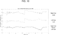
- FIG. 10 illustrates a first graph showing right eye determined centroids versus time.
- FIG. 10 illustrates a second graph showing left eye determined centroids versus time.
- FIG. 10 further illustrates a third graph which comprises for each time value, the difference between a left eye x coordinate for that time value from a right eye x coordinate for that time value.
- step 590 and referring to FIG. 10 the dynamic IPDs calculated in step 570 are graphically displayed versus time.
- a desirable product requirement of a CI screener is the ability to make measurements on a subject with prescription eyeglasses or contact lenses.
- this method works well without glasses or with contact lenses, providing a distinctive glint reflection that is easy to detect using established machine vision methods.
- this does not work well while wearing prescription glasses because the prescription lenses also reflect the infrared light, creating an additional glint blocking and obscuring the camera view of the glint/pupil/eye.
- a standard way to suppress the glasses' reflection is to use a diffuse lighting illumination configuration. This is typically done with a ring structure of LEDs. However, this may be expensive, requiring multiple LEDs in a complex mechanical ring mount. Even more importantly, it may raise eye safety concerns with so many LEDs in close proximity to the eye.
- FIG. 17 shows a unique diffuse illumination method composed of a flexible side glow optical fiber that has a superb light transmission for bright and consistent illumination using one or two LEDs.
- FIG. 18 When mounted in an eye mask in a ring or oval configuration as shown in FIG. 18 , it creates a diffuse eye illumination method that suppresses glint reflections from the eyeglasses as well as the eye.
- these features could be added to any of the above embodiments.
- the standard clinical methods to screen for CI include a near point convergence test. This test requires a subject to adjust his focus as well as his convergence while a visual stimulus is moved in toward his nose. In this way, the subject's ability to simultaneously accommodate and converge is dynamically tested.
- FIG. 2B shows a mechanical configuration which allows the system to explicitly mimic the clinical near point test.
- it is a single visual stimulus display configuration with a variable image distance, all under computer control.
- FIG. 19 shows an example embodiment prototype.
Landscapes
- Health & Medical Sciences (AREA)
- Life Sciences & Earth Sciences (AREA)
- Engineering & Computer Science (AREA)
- Physics & Mathematics (AREA)
- General Health & Medical Sciences (AREA)
- Medical Informatics (AREA)
- Ophthalmology & Optometry (AREA)
- Biomedical Technology (AREA)
- Heart & Thoracic Surgery (AREA)
- Molecular Biology (AREA)
- Surgery (AREA)
- Animal Behavior & Ethology (AREA)
- Public Health (AREA)
- Veterinary Medicine (AREA)
- Biophysics (AREA)
- Theoretical Computer Science (AREA)
- General Physics & Mathematics (AREA)
- Computer Vision & Pattern Recognition (AREA)
- Multimedia (AREA)
- Nuclear Medicine, Radiotherapy & Molecular Imaging (AREA)
- Radiology & Medical Imaging (AREA)
- Quality & Reliability (AREA)
- Human Computer Interaction (AREA)
- Physiology (AREA)
- Dentistry (AREA)
- Oral & Maxillofacial Surgery (AREA)
- Pathology (AREA)
- Eye Examination Apparatus (AREA)
- Signal Processing (AREA)
Claims (15)
- Einrichtung zum Screening einer Person auf Konvergenzinsuffizienz (CI), wobei die Einrichtung umfasst:ein Binokular umfassend ein erstes Okular, um ein erstes Auge der Person aufzunehmen, ein zweites Okular, um ein zweites Auge der Person aufzunehmen, einen ersten Bildsensor angrenzend an das erste Okular und einen zweiten Bildsensor angrenzend an das zweite Okular;eine Anzeige angrenzend an das Binokular; undeinen Prozessor und einen zugeordneten Speicher, der mit der Anzeige zusammenwirkt und ausgebildet ist, ummit dem ersten Bildsensor eine Bewegung des ersten Auges aufzuzeichnen,um mit dem zweiten Bildsensor eine Bewegung des zweiten Auges aufzuzeichnen,um auf der Anzeige einen ersten visuellen Reiz und einen zweiten visuellen Reiz darzustellen,um auf alternierende Weise eine konvergente und eine divergente Bewegung in dem ersten visuellen Reiz und dem zweiten visuellen Reiz entlang einer visuellen Reizbahn hervorzurufen,um entsprechende Schwerpunktspositionen des zweiten Auges und des ersten Auges während der konvergenten und divergenten Bewegung des ersten visuellen Stimulus und des zweiten visuellen Stimulus zu ermitteln, undum einen Augenabstand (IPD) zu berechnen und um den Augenabstand mit der visuellen Reizbahn zu vergleichen, um einen dynamischen IPD zu erhalten, wobei der IPD als ein Indikator dafür dient, ob die Person CI hat.
- Einrichtung nach Anspruch 1, bei der die Dauer von sowohl der konvergenten Bewegung als auch der divergenten Bewegung 80-100 Sekunden beträgt.
- Einrichtung nach Anspruch 1 oder 2 ferner umfassend eine erste Infrarotquelle (IR), die ausgebildet ist, um das erste Auge zu bestrahlen und eine zweite Infrarotbeleuchtung (IR), die ausgebildet ist, um das zweite Auge zu bestrahlen, und wobei der Prozessor und der Speicher ausgebildet sind, um eine erste Vielzahl Videoframes zu erzeugen, die die Bewegung des ersten Auges zeigen, und um eine zweite Vielzahl Videoframes zu erzeugen, die die Bewegung des zweiten Auges zeigen.
- Einrichtung nach Anspruch 3, bei der der Prozessor und der Speicher ausgebildet sind, um zweite Blinkpixel zu ermitteln umfassend zweite Augenblinkvorgänge in der zweiten Vielzahl Videoframes;
um aus einer dritten Vielzahl Videoframes durch Entfernen der zweiten Blinkpixel von der zweiten Vielzahl Videoframes erste Blinkpixel zu ermitteln, umfassend erste Augenblinkvorgänge in der ersten Vielzahl Videoframes; und
um eine vierte Vielzahl Videoframes auszubilden durch Entfernen der ersten Blinkpixel von der ersten Vielzahl Videoframes. - Einrichtung nach Anspruch 3 oder 4, bei der der Prozessor und Speicher ausgebildet sind, um die erste Vielzahl Videoframes zu erzeugen durch Durchführen von zumindest:Filtern von jeder der ersten Vielzahl Videoframes umfassend einen Pixelintensitätsgrenzwert, um eine dritte Vielzahl Videoframes auszubilden, wobei jeder der dritten Vielzahl Videoframes einen schwarzen Hintergrund in Kombination mit einem weißen Hintergrund, ein erstes Augenbild, die dritte Vielzahl Videoframes umfassend eine N-Anzahl Videoframes umfasst;Filtern von sowohl der zweiten Vielzahl Videoframes verwendend den Pixelintensitätsgrenzwert, um eine vierte Vielzahl Videoframes auszubilden, wobei jeder der vierten Vielzahl Videoframes einen schwarzen Hintergrund in Verbindung mit einem weißen Hintergrund, ein zweites Augenbild sowie die vierte Vielzahl Videoframes umfassend eine M-Anzahl Videoframes umfasst;Ermitteln für jeden der dritten Vielzahl Videoframes x- und y-Koordinaten für den ersten Pupillenschwerpunkt; undErzeugen einer ersten Vielzahl x-Koordinatendatensätze;wobei ein i-ter x-Koordinatendatensatz einen Ort eines i-ten zweiten Pupillenschwerpunkts wiedergibt;wobei i größer als oder gleich 1 und geringer als oder gleich N ist;Ermitteln für jeden der Vielzahl Videoframes x- und y-Koordinaten für einen zweiten Augenpupillenschwerpunkt; undErzeugen einer zweiten Vielzahl an x-Koordinatendatensätze;wobei ein j-ter x-Koordinatendatensatz einen Ort eines j-ten ersten Pupillenschwerpunkts wiedergibt;wobei j größer als oder gleich 1 und geringer als oder gleich M ist.
- Einrichtung nach Anspruch 5, bei der der Prozessor und Speicher ausgebildet sind, um graphisch eine erste Kurve umfassend N x-Koordinatendatensätze über der Zeit darzustellen; und um graphisch eine zweite Kurve darzustellen, umfassend M x-Koordinatendatensätze über der Zeit.
- Einrichtung nach Anspruch 6, bei der der Prozessor und Speicher ausgebildet sind, um:i=1 und j=1 zu setzen;um den i-ten x-Koordinatendatensatz von dem j-ten x-Koordinatensatz zu subtrahieren, um einen k-ten x-Koordinatendatensatz auszubilden, wobei jeder k-te x-Koordinatendatensatz einen h-ten dynamischen IPD wiedergibt;wobei, wenn i geringer als N ist, i=i+1 gesetzt wird;wobei, wenn j geringer als M ist, j=j+1 gesetzt wird; undwobei das Einstellen und Subtrahieren wiederholt wird bis zumindest i=1 und/oder j=M erfüllt ist.
- Einrichtung nach Anspruch 7, bei der der Prozessor und Speicher ausgebildet sind, um eine dritte Kurve auszubilden, umfassend jeden der h-ten dynamischen IPD über der Zeit.
- Einrichtung nach Anspruch 8, bei der der Prozessor und Speicher ausgebildet sind, um:einen ersten im Wesentlichen linearen Abschnitt der dritten Kurve zu identifizieren, wobei der erste im Wesentlichen lineare Abschnitt eine positive Steigung umfasst;einen zweiten im Wesentlichen linearen Abschnitt der dritten Kurve zu identifizieren, wobei der zweite im Wesentlichen lineare Abschnitt eine negative Steigung umfasst;eine graphische Anzeige der visuellen Reizbahn zu erzeugen, wobei die graphische Anzeige einen ersten linearen Abschnitt umfassend eine positive Neigung und einen zweiten linearen Abschnitt umfassend eine negative Neigung umfasst;die dritte Kurve auf die graphische Anzeige der visuellen Reizbahn zu überlappen; unddie dritte Kurve einzustellen, um auf die graphische Anzeige der visuellen Reizbahn zu passen.
- Einrichtung nach einem der vorhergehenden Ansprüche, bei der der Prozessor und Speicher ausgebildet sind, um die dynamische IPD mit der visuellen Reizbahn zu vergleichen, durch zumindest ausführen von:Optimieren eines Graphs von dynamischen IPDs mit zumindest einem Parameter; undVereinen des optimierten Graphen der dynamischen IPDs mit der visuellen Reizbahn.
- Verfahren zum Ermitteln eines Indikators, ob eine Person Konvergenzinsuffizienz (CI) hat, wobei das Verfahren umfasst:Aufzeichnen mit einem ersten Bildsensor einer Bewegung eines ersten Auges der Person;Aufzeichnen mit einem zweiten Bildsensor einer Bewegung eines zweiten Auges der Person;Anzeigen auf einer Anzeige eines ersten visuellen Reizes und eines zweiten visuellen Reizes; undHervorrufen auf alternierende Weise einer konvergierenden Bewegung und einer divergierenden Bewegung in dem ersten visuellen Reiz und dem zweiten visuellen Reiz entlang einer visuellen Reizbahn;Ermitteln von entsprechenden Schwerpunktpositionen des ersten Auges und des zweiten Auges während der konvergenten und divergenten Bewegung des ersten visuellen Stimulus und des zweiten visuellen Stimulus; undBerechnen eines Augenabstandes (IPD) und Vergleichen des Augenabstandes mit der visuellen Reizbahn, um eine dynamische IPD zu erhalten, wobei die IPD als ein Indikator dafür dient, ob die Person CI hat.
- Verfahren nach Anspruch 11, bei dem eine Dauer von jeder der konvergenten Bewegung und der divergenten Bewegung 80 bis 100 Sekunden beträgt.
- Verfahren nach Anspruch 11 oder 12 ferner umfassend:Verwenden einer ersten Infrarotquelle (IR), die ausgebildet ist, um das erste Auge zu bestrahlen, und einer zweiten IR-Beleuchtung, die ausgebildet ist, um das zweite Auge zu bestrahlen; undErzeugen einer ersten Vielzahl Videoframes, die eine Bewegung des ersten Auges zeigt, und Erzeugen einer zweiten Vielzahl Videoframes, die eine Bewegung des zweiten Auges zeigt.
- Verfahren nach Anspruch 13, ferner umfassend:Identifizieren zweiter Blinkpixel umfassend zweite Augenblinkvorgänge in der zweiten Vielzahl Videoframes;Ausbilden einer dritten Vielzahl Videoframes durch Entfernen der zweiten Blinkpixel aus der zweiten Vielzahl Videoframes;Identifizieren der ersten Blinkpixel umfassend erste Augenblinkvorgänge in der ersten Vielzahl Videoframes; undAusbilden einer vierten Vielzahl Videoframes durch Entfernen der ersten Blinkpixel aus der ersten Vielzahl Videoframes.
- Verfahren nach Anspruch 13 oder 14, bei dem das Erzeugen der ersten Vielzahl Videoframes umfasst:Filtern von jedem der ersten Vielzahl Videoframes unter Verwendung eines Pixelintensitätsgrenzwertes, um eine dritte Vielzahl Videoframes auszubilden, wobei jeder der dritten Vielzahl Videoframes einen schwarzen Hintergrund in Verbindung mit einem weißen Hintergrund, ein erstes Augenbild, die dritte Vielzahl Videoframes umfassend eine N-Anzahl Videoframes umfasst;Filtern von jeder der zweiten Vielzahl Videoframes unter Verwendung des Pixelintensitätsgrenzwertes, um eine vierte Vielzahl Videoframes auszubilden, wobei jeder der vierten Vielzahl Videoframes einen schwarzen Hintergrund in Verbindung mit einem weißen Hintergrund, ein zweites Augenbild, die vierte Vielzahl Videoframes umfassend eine M-Anzahl Videoframes umfasst;Ermitteln für jeden der dritten Vielzahl Videoframes x- und y-Koordinaten für einen ersten Augenpupillenschwerpunkt; undErzeugen einer ersten Vielzahl x-Koordinatendatensätze;wobei ein i-ter x-Koordinatendatensatz einen Ort eines i-ten zweiten Pupillenschwerpunktes wiedergibt;wobei i größer als oder gleich 1 und geringer als oder gleich N ist;Ermitteln für jeden der vierten Vielzahl Videoframes x- und y-Koordinaten für einen zweiten Augenpupillenschwerpunkt; undErzeugen einer zweiten Vielzahl x-Koordinatendatensätze;wobei ein j-ter x-Koordinatendatensatz einen Ort eines j-ten ersten Pupillenschwerpunkts wiedergibt;wobei j größer als oder gleich 1 und geringer als oder gleich M ist.
Applications Claiming Priority (1)
| Application Number | Priority Date | Filing Date | Title |
|---|---|---|---|
| US201662385136P | 2016-09-08 | 2016-09-08 |
Publications (2)
| Publication Number | Publication Date |
|---|---|
| EP3292811A1 EP3292811A1 (de) | 2018-03-14 |
| EP3292811B1 true EP3292811B1 (de) | 2018-12-19 |
Family
ID=61131816
Family Applications (2)
| Application Number | Title | Priority Date | Filing Date |
|---|---|---|---|
| EP17190231.5A Not-in-force EP3292810B1 (de) | 2016-09-08 | 2017-09-08 | Vorrichtung zum screening von konvergenzinsuffizienz und zugehörige computerimplementierte verfahren |
| EP17190232.3A Not-in-force EP3292811B1 (de) | 2016-09-08 | 2017-09-08 | Vorrichtung zum screening von konvergenzinsuffizienz und zugehörige verfahren |
Family Applications Before (1)
| Application Number | Title | Priority Date | Filing Date |
|---|---|---|---|
| EP17190231.5A Not-in-force EP3292810B1 (de) | 2016-09-08 | 2017-09-08 | Vorrichtung zum screening von konvergenzinsuffizienz und zugehörige computerimplementierte verfahren |
Country Status (2)
| Country | Link |
|---|---|
| US (2) | US10188292B2 (de) |
| EP (2) | EP3292810B1 (de) |
Families Citing this family (3)
| Publication number | Priority date | Publication date | Assignee | Title |
|---|---|---|---|---|
| US11793403B2 (en) | 2020-03-16 | 2023-10-24 | Vivid Vision, Inc. | Apparatus, systems, and methods for vision assessment and treatment |
| EP4426184A4 (de) * | 2021-11-02 | 2025-12-03 | Evolution Optiks Ltd | Kopfmontierbare beurteilungsvorrichtung und verfahren zur verwendung davon |
| IL320532A (en) * | 2022-10-31 | 2025-06-01 | Carmel Haifa Univ Economic Corporation Ltd | System and method for diagnosis and treatment of various movement disorders and diseases of the eye |
Family Cites Families (32)
| Publication number | Priority date | Publication date | Assignee | Title |
|---|---|---|---|---|
| US5026151A (en) | 1989-06-23 | 1991-06-25 | Mentor O & O, Inc. | Visual function tester with binocular vision testing |
| US5355895A (en) | 1993-07-20 | 1994-10-18 | Hay S Hutson | Ocular disease detection apparatus |
| US5825458A (en) | 1995-03-02 | 1998-10-20 | Cooper; Clifford Warren | Personal binocular trainer |
| DE19704197A1 (de) | 1997-02-05 | 1998-08-06 | Zeiss Carl Jena Gmbh | Anordnung zur subjektivem Refraktionsbestimmung und/oder zur Bestimmung anderer Sehfunktionen |
| US5953102A (en) | 1997-07-23 | 1999-09-14 | Berry; Francis D. | Method for substantially objective testing of the visual capacity of a test subject |
| JP2000013818A (ja) | 1998-06-23 | 2000-01-14 | Nec Corp | 立体表示装置及び立体表示方法 |
| AUPQ842800A0 (en) | 2000-06-28 | 2000-07-20 | Aivision Pty Ltd | Flat screen vision testing |
| JP2002017677A (ja) | 2000-07-07 | 2002-01-22 | Hamamatsu Photonics Kk | 輻輳角測定装置 |
| GB0210288D0 (en) | 2002-05-04 | 2002-06-12 | Univ Nottingham | Ocular display apparatus for assessment and measurement of and for treatment of ocular disorders, and methods therefor |
| US20080212032A1 (en) | 2002-05-09 | 2008-09-04 | Seiller Barry L | Visual skill diagnostic and therapeutic system and process |
| US7326060B2 (en) * | 2002-05-09 | 2008-02-05 | Barry Seiller | Visual performance evaluation and training system |
| US7309125B2 (en) | 2005-06-09 | 2007-12-18 | Vladimir Pugach | Method and apparatus for detecting abnormalities in spatial perception |
| US8403480B2 (en) | 2006-01-24 | 2013-03-26 | University Of Tennessee Research Foundation | Adaptive photoscreening system |
| US8668334B2 (en) | 2006-02-27 | 2014-03-11 | Vital Art And Science Incorporated | Vision measurement and training system and method of operation thereof |
| JP2008246143A (ja) | 2007-03-30 | 2008-10-16 | Hamamatsu Photonics Kk | 瞳孔測定装置 |
| US8016420B2 (en) | 2007-05-17 | 2011-09-13 | Amo Development Llc. | System and method for illumination and fixation with ophthalmic diagnostic instruments |
| US20100324454A1 (en) | 2009-06-22 | 2010-12-23 | Kircher John C | Deception detection using oculomotor movements |
| WO2011051955A2 (en) | 2009-11-02 | 2011-05-05 | Jonathan Bentwich | Computerized system or device and method for diagnosis and treatment of human, physical and planetary conditions |
| EP2329761A1 (de) | 2009-12-02 | 2011-06-08 | RetCorr AB | Vorrichtung und Verfahren zur Errichtung und/oder Verbesserung des Binokularsehens |
| CA2783787A1 (en) | 2010-02-12 | 2011-08-18 | Exxonmobil Upstream Research Company | Method and system for creating history-matched simulation models |
| DE102011054833A1 (de) * | 2010-10-29 | 2012-05-03 | Hoya Corp. | Verfahren zum Messen der binokularen Sehleistung, Programm zum Messen der binokularen Sehleistung, Verfahren zum Entwerfen von Brillengläsern und Verfahren zur Herstellung von Brillengläsern |
| US8678592B2 (en) | 2011-03-09 | 2014-03-25 | The Johns Hopkins University | Method and apparatus for detecting fixation of at least one eye of a subject on a target |
| CN103281959A (zh) * | 2011-05-20 | 2013-09-04 | 松下电器产业株式会社 | 视觉疲劳度测定装置、视觉疲劳度测定方法、视觉疲劳度测定系统及三维眼镜 |
| JP6366510B2 (ja) | 2012-03-09 | 2018-08-01 | オキュスペクト オサケ ユキチュア | 視覚系の機能を評価するためのシステムの作動方法および装置 |
| DE102012022662A1 (de) | 2012-11-21 | 2014-05-22 | Friedrich-Alexander-Universität Erlangen-Nürnberg | Vorrichtung und Verfahren zur Überprüfung der menschlichen Sehfähigkeit |
| US9788714B2 (en) | 2014-07-08 | 2017-10-17 | Iarmourholdings, Inc. | Systems and methods using virtual reality or augmented reality environments for the measurement and/or improvement of human vestibulo-ocular performance |
| CN103393398A (zh) | 2013-07-31 | 2013-11-20 | 武汉优视医疗科技有限公司 | 一种微电脑同视机 |
| JP6608137B2 (ja) | 2014-01-03 | 2019-11-20 | ハーマン インターナショナル インダストリーズ インコーポレイテッド | ディスプレイ上の両眼転導検出 |
| US20160106315A1 (en) | 2014-05-30 | 2016-04-21 | Umoove Services Ltd. | System and method of diagnosis using gaze and eye tracking |
| EP3177960B1 (de) | 2014-08-04 | 2018-05-16 | Essilor International | Brille mit einem paar von gleitsichtgläsern |
| US9504380B1 (en) * | 2015-06-30 | 2016-11-29 | Evecarrot Innovations Corp. | System and method for assessing human visual processing |
| CA3020390A1 (en) * | 2016-04-08 | 2017-10-12 | Vizzario, Inc. | Methods and systems for obtaining, aggregating, and analyzing vision data to assess a person's vision performance |
-
2017
- 2017-09-07 US US15/697,880 patent/US10188292B2/en not_active Expired - Fee Related
- 2017-09-07 US US15/697,838 patent/US10188291B2/en not_active Expired - Fee Related
- 2017-09-08 EP EP17190231.5A patent/EP3292810B1/de not_active Not-in-force
- 2017-09-08 EP EP17190232.3A patent/EP3292811B1/de not_active Not-in-force
Non-Patent Citations (1)
| Title |
|---|
| None * |
Also Published As
| Publication number | Publication date |
|---|---|
| US10188292B2 (en) | 2019-01-29 |
| EP3292810A1 (de) | 2018-03-14 |
| US20180064333A1 (en) | 2018-03-08 |
| EP3292811A1 (de) | 2018-03-14 |
| US20180064329A1 (en) | 2018-03-08 |
| US10188291B2 (en) | 2019-01-29 |
| EP3292810B1 (de) | 2018-12-19 |
Similar Documents
| Publication | Publication Date | Title |
|---|---|---|
| JP7441915B2 (ja) | ライトフィールドプロセッサシステム | |
| US11612316B2 (en) | Medical system and method operable to control sensor-based wearable devices for examining eyes | |
| JP6212115B2 (ja) | 人物の他覚的眼屈折及び少なくとも1つの幾何学的形態パラメータを測定する装置及び方法 | |
| EP3247256B1 (de) | Nverfahren und system für automatischen test des sehvermögens | |
| AU2014308570B2 (en) | Spectacles and method for determining the centre of the pupil of both of the wearer's eyes | |
| CN114025659B (zh) | 眼睛的屈光不正确定 | |
| US20170092007A1 (en) | Methods and Devices for Providing Enhanced Visual Acuity | |
| CN111511318A (zh) | 数字治疗矫正眼镜 | |
| JP7165994B2 (ja) | 眼の計測を収集するための方法及びデバイス | |
| CN109310314A (zh) | 用于眼位偏斜测量的移动装置应用 | |
| US20200081256A1 (en) | Methods and systems for diagnosing and treating eyes using light therapy | |
| KR20200067398A (ko) | 가상현실 기반의 휴대용 안진 검사장치 및 이를 이용한 검진 방법 | |
| EP3292810B1 (de) | Vorrichtung zum screening von konvergenzinsuffizienz und zugehörige computerimplementierte verfahren | |
| JP2016087291A (ja) | 瞳孔・視線計測装置および照明システム | |
| RU2589623C2 (ru) | Способ мониторинга движения глаз и устройство для его реализации |
Legal Events
| Date | Code | Title | Description |
|---|---|---|---|
| PUAI | Public reference made under article 153(3) epc to a published international application that has entered the european phase |
Free format text: ORIGINAL CODE: 0009012 |
|
| STAA | Information on the status of an ep patent application or granted ep patent |
Free format text: STATUS: THE APPLICATION HAS BEEN PUBLISHED |
|
| AK | Designated contracting states |
Kind code of ref document: A1 Designated state(s): AL AT BE BG CH CY CZ DE DK EE ES FI FR GB GR HR HU IE IS IT LI LT LU LV MC MK MT NL NO PL PT RO RS SE SI SK SM TR |
|
| AX | Request for extension of the european patent |
Extension state: BA ME |
|
| STAA | Information on the status of an ep patent application or granted ep patent |
Free format text: STATUS: REQUEST FOR EXAMINATION WAS MADE |
|
| 17P | Request for examination filed |
Effective date: 20180411 |
|
| RBV | Designated contracting states (corrected) |
Designated state(s): AL AT BE BG CH CY CZ DE DK EE ES FI FR GB GR HR HU IE IS IT LI LT LU LV MC MK MT NL NO PL PT RO RS SE SI SK SM TR |
|
| REG | Reference to a national code |
Ref country code: DE Ref legal event code: R079 Ref document number: 602017001466 Country of ref document: DE Free format text: PREVIOUS MAIN CLASS: A61B0003080000 Ipc: A61B0003000000 |
|
| RIC1 | Information provided on ipc code assigned before grant |
Ipc: A61B 3/08 20060101ALI20180628BHEP Ipc: A61B 3/113 20060101ALI20180628BHEP Ipc: A61B 3/00 20060101AFI20180628BHEP Ipc: A61B 3/14 20060101ALI20180628BHEP Ipc: A61B 3/09 20060101ALI20180628BHEP Ipc: A61B 3/11 20060101ALI20180628BHEP |
|
| GRAP | Despatch of communication of intention to grant a patent |
Free format text: ORIGINAL CODE: EPIDOSNIGR1 |
|
| STAA | Information on the status of an ep patent application or granted ep patent |
Free format text: STATUS: GRANT OF PATENT IS INTENDED |
|
| INTG | Intention to grant announced |
Effective date: 20180803 |
|
| GRAS | Grant fee paid |
Free format text: ORIGINAL CODE: EPIDOSNIGR3 |
|
| GRAA | (expected) grant |
Free format text: ORIGINAL CODE: 0009210 |
|
| STAA | Information on the status of an ep patent application or granted ep patent |
Free format text: STATUS: THE PATENT HAS BEEN GRANTED |
|
| AK | Designated contracting states |
Kind code of ref document: B1 Designated state(s): AL AT BE BG CH CY CZ DE DK EE ES FI FR GB GR HR HU IE IS IT LI LT LU LV MC MK MT NL NO PL PT RO RS SE SI SK SM TR |
|
| REG | Reference to a national code |
Ref country code: GB Ref legal event code: FG4D |
|
| REG | Reference to a national code |
Ref country code: CH Ref legal event code: EP |
|
| REG | Reference to a national code |
Ref country code: IE Ref legal event code: FG4D |
|
| REG | Reference to a national code |
Ref country code: DE Ref legal event code: R096 Ref document number: 602017001466 Country of ref document: DE |
|
| REG | Reference to a national code |
Ref country code: AT Ref legal event code: REF Ref document number: 1077788 Country of ref document: AT Kind code of ref document: T Effective date: 20190115 |
|
| REG | Reference to a national code |
Ref country code: NL Ref legal event code: MP Effective date: 20181219 |
|
| PG25 | Lapsed in a contracting state [announced via postgrant information from national office to epo] |
Ref country code: HR Free format text: LAPSE BECAUSE OF FAILURE TO SUBMIT A TRANSLATION OF THE DESCRIPTION OR TO PAY THE FEE WITHIN THE PRESCRIBED TIME-LIMIT Effective date: 20181219 Ref country code: LV Free format text: LAPSE BECAUSE OF FAILURE TO SUBMIT A TRANSLATION OF THE DESCRIPTION OR TO PAY THE FEE WITHIN THE PRESCRIBED TIME-LIMIT Effective date: 20181219 Ref country code: FI Free format text: LAPSE BECAUSE OF FAILURE TO SUBMIT A TRANSLATION OF THE DESCRIPTION OR TO PAY THE FEE WITHIN THE PRESCRIBED TIME-LIMIT Effective date: 20181219 Ref country code: LT Free format text: LAPSE BECAUSE OF FAILURE TO SUBMIT A TRANSLATION OF THE DESCRIPTION OR TO PAY THE FEE WITHIN THE PRESCRIBED TIME-LIMIT Effective date: 20181219 Ref country code: BG Free format text: LAPSE BECAUSE OF FAILURE TO SUBMIT A TRANSLATION OF THE DESCRIPTION OR TO PAY THE FEE WITHIN THE PRESCRIBED TIME-LIMIT Effective date: 20190319 Ref country code: NO Free format text: LAPSE BECAUSE OF FAILURE TO SUBMIT A TRANSLATION OF THE DESCRIPTION OR TO PAY THE FEE WITHIN THE PRESCRIBED TIME-LIMIT Effective date: 20190319 |
|
| REG | Reference to a national code |
Ref country code: LT Ref legal event code: MG4D |
|
| REG | Reference to a national code |
Ref country code: AT Ref legal event code: MK05 Ref document number: 1077788 Country of ref document: AT Kind code of ref document: T Effective date: 20181219 |
|
| PG25 | Lapsed in a contracting state [announced via postgrant information from national office to epo] |
Ref country code: SE Free format text: LAPSE BECAUSE OF FAILURE TO SUBMIT A TRANSLATION OF THE DESCRIPTION OR TO PAY THE FEE WITHIN THE PRESCRIBED TIME-LIMIT Effective date: 20181219 Ref country code: RS Free format text: LAPSE BECAUSE OF FAILURE TO SUBMIT A TRANSLATION OF THE DESCRIPTION OR TO PAY THE FEE WITHIN THE PRESCRIBED TIME-LIMIT Effective date: 20181219 Ref country code: GR Free format text: LAPSE BECAUSE OF FAILURE TO SUBMIT A TRANSLATION OF THE DESCRIPTION OR TO PAY THE FEE WITHIN THE PRESCRIBED TIME-LIMIT Effective date: 20190320 Ref country code: AL Free format text: LAPSE BECAUSE OF FAILURE TO SUBMIT A TRANSLATION OF THE DESCRIPTION OR TO PAY THE FEE WITHIN THE PRESCRIBED TIME-LIMIT Effective date: 20181219 |
|
| PG25 | Lapsed in a contracting state [announced via postgrant information from national office to epo] |
Ref country code: NL Free format text: LAPSE BECAUSE OF FAILURE TO SUBMIT A TRANSLATION OF THE DESCRIPTION OR TO PAY THE FEE WITHIN THE PRESCRIBED TIME-LIMIT Effective date: 20181219 |
|
| PG25 | Lapsed in a contracting state [announced via postgrant information from national office to epo] |
Ref country code: ES Free format text: LAPSE BECAUSE OF FAILURE TO SUBMIT A TRANSLATION OF THE DESCRIPTION OR TO PAY THE FEE WITHIN THE PRESCRIBED TIME-LIMIT Effective date: 20181219 Ref country code: IT Free format text: LAPSE BECAUSE OF FAILURE TO SUBMIT A TRANSLATION OF THE DESCRIPTION OR TO PAY THE FEE WITHIN THE PRESCRIBED TIME-LIMIT Effective date: 20181219 Ref country code: PL Free format text: LAPSE BECAUSE OF FAILURE TO SUBMIT A TRANSLATION OF THE DESCRIPTION OR TO PAY THE FEE WITHIN THE PRESCRIBED TIME-LIMIT Effective date: 20181219 Ref country code: CZ Free format text: LAPSE BECAUSE OF FAILURE TO SUBMIT A TRANSLATION OF THE DESCRIPTION OR TO PAY THE FEE WITHIN THE PRESCRIBED TIME-LIMIT Effective date: 20181219 Ref country code: PT Free format text: LAPSE BECAUSE OF FAILURE TO SUBMIT A TRANSLATION OF THE DESCRIPTION OR TO PAY THE FEE WITHIN THE PRESCRIBED TIME-LIMIT Effective date: 20190419 |
|
| PG25 | Lapsed in a contracting state [announced via postgrant information from national office to epo] |
Ref country code: SK Free format text: LAPSE BECAUSE OF FAILURE TO SUBMIT A TRANSLATION OF THE DESCRIPTION OR TO PAY THE FEE WITHIN THE PRESCRIBED TIME-LIMIT Effective date: 20181219 Ref country code: SM Free format text: LAPSE BECAUSE OF FAILURE TO SUBMIT A TRANSLATION OF THE DESCRIPTION OR TO PAY THE FEE WITHIN THE PRESCRIBED TIME-LIMIT Effective date: 20181219 Ref country code: EE Free format text: LAPSE BECAUSE OF FAILURE TO SUBMIT A TRANSLATION OF THE DESCRIPTION OR TO PAY THE FEE WITHIN THE PRESCRIBED TIME-LIMIT Effective date: 20181219 Ref country code: RO Free format text: LAPSE BECAUSE OF FAILURE TO SUBMIT A TRANSLATION OF THE DESCRIPTION OR TO PAY THE FEE WITHIN THE PRESCRIBED TIME-LIMIT Effective date: 20181219 Ref country code: IS Free format text: LAPSE BECAUSE OF FAILURE TO SUBMIT A TRANSLATION OF THE DESCRIPTION OR TO PAY THE FEE WITHIN THE PRESCRIBED TIME-LIMIT Effective date: 20190419 |
|
| REG | Reference to a national code |
Ref country code: DE Ref legal event code: R097 Ref document number: 602017001466 Country of ref document: DE |
|
| PLBE | No opposition filed within time limit |
Free format text: ORIGINAL CODE: 0009261 |
|
| STAA | Information on the status of an ep patent application or granted ep patent |
Free format text: STATUS: NO OPPOSITION FILED WITHIN TIME LIMIT |
|
| PG25 | Lapsed in a contracting state [announced via postgrant information from national office to epo] |
Ref country code: AT Free format text: LAPSE BECAUSE OF FAILURE TO SUBMIT A TRANSLATION OF THE DESCRIPTION OR TO PAY THE FEE WITHIN THE PRESCRIBED TIME-LIMIT Effective date: 20181219 Ref country code: DK Free format text: LAPSE BECAUSE OF FAILURE TO SUBMIT A TRANSLATION OF THE DESCRIPTION OR TO PAY THE FEE WITHIN THE PRESCRIBED TIME-LIMIT Effective date: 20181219 |
|
| 26N | No opposition filed |
Effective date: 20190920 |
|
| PG25 | Lapsed in a contracting state [announced via postgrant information from national office to epo] |
Ref country code: SI Free format text: LAPSE BECAUSE OF FAILURE TO SUBMIT A TRANSLATION OF THE DESCRIPTION OR TO PAY THE FEE WITHIN THE PRESCRIBED TIME-LIMIT Effective date: 20181219 |
|
| PG25 | Lapsed in a contracting state [announced via postgrant information from national office to epo] |
Ref country code: TR Free format text: LAPSE BECAUSE OF FAILURE TO SUBMIT A TRANSLATION OF THE DESCRIPTION OR TO PAY THE FEE WITHIN THE PRESCRIBED TIME-LIMIT Effective date: 20181219 |
|
| PG25 | Lapsed in a contracting state [announced via postgrant information from national office to epo] |
Ref country code: MC Free format text: LAPSE BECAUSE OF FAILURE TO SUBMIT A TRANSLATION OF THE DESCRIPTION OR TO PAY THE FEE WITHIN THE PRESCRIBED TIME-LIMIT Effective date: 20181219 |
|
| REG | Reference to a national code |
Ref country code: DE Ref legal event code: R082 Ref document number: 602017001466 Country of ref document: DE |
|
| PG25 | Lapsed in a contracting state [announced via postgrant information from national office to epo] |
Ref country code: LU Free format text: LAPSE BECAUSE OF NON-PAYMENT OF DUE FEES Effective date: 20190908 Ref country code: IE Free format text: LAPSE BECAUSE OF NON-PAYMENT OF DUE FEES Effective date: 20190908 |
|
| REG | Reference to a national code |
Ref country code: BE Ref legal event code: MM Effective date: 20190930 |
|
| PG25 | Lapsed in a contracting state [announced via postgrant information from national office to epo] |
Ref country code: BE Free format text: LAPSE BECAUSE OF NON-PAYMENT OF DUE FEES Effective date: 20190930 |
|
| PGFP | Annual fee paid to national office [announced via postgrant information from national office to epo] |
Ref country code: FR Payment date: 20200915 Year of fee payment: 4 Ref country code: DE Payment date: 20200915 Year of fee payment: 4 |
|
| REG | Reference to a national code |
Ref country code: CH Ref legal event code: PL |
|
| PG25 | Lapsed in a contracting state [announced via postgrant information from national office to epo] |
Ref country code: CY Free format text: LAPSE BECAUSE OF FAILURE TO SUBMIT A TRANSLATION OF THE DESCRIPTION OR TO PAY THE FEE WITHIN THE PRESCRIBED TIME-LIMIT Effective date: 20181219 |
|
| PG25 | Lapsed in a contracting state [announced via postgrant information from national office to epo] |
Ref country code: MT Free format text: LAPSE BECAUSE OF FAILURE TO SUBMIT A TRANSLATION OF THE DESCRIPTION OR TO PAY THE FEE WITHIN THE PRESCRIBED TIME-LIMIT Effective date: 20181219 Ref country code: HU Free format text: LAPSE BECAUSE OF FAILURE TO SUBMIT A TRANSLATION OF THE DESCRIPTION OR TO PAY THE FEE WITHIN THE PRESCRIBED TIME-LIMIT; INVALID AB INITIO Effective date: 20170908 |
|
| PG25 | Lapsed in a contracting state [announced via postgrant information from national office to epo] |
Ref country code: LI Free format text: LAPSE BECAUSE OF NON-PAYMENT OF DUE FEES Effective date: 20200930 Ref country code: CH Free format text: LAPSE BECAUSE OF NON-PAYMENT OF DUE FEES Effective date: 20200930 |
|
| REG | Reference to a national code |
Ref country code: DE Ref legal event code: R119 Ref document number: 602017001466 Country of ref document: DE |
|
| GBPC | Gb: european patent ceased through non-payment of renewal fee |
Effective date: 20210908 |
|
| PG25 | Lapsed in a contracting state [announced via postgrant information from national office to epo] |
Ref country code: MK Free format text: LAPSE BECAUSE OF FAILURE TO SUBMIT A TRANSLATION OF THE DESCRIPTION OR TO PAY THE FEE WITHIN THE PRESCRIBED TIME-LIMIT Effective date: 20181219 |
|
| PG25 | Lapsed in a contracting state [announced via postgrant information from national office to epo] |
Ref country code: GB Free format text: LAPSE BECAUSE OF NON-PAYMENT OF DUE FEES Effective date: 20210908 Ref country code: FR Free format text: LAPSE BECAUSE OF NON-PAYMENT OF DUE FEES Effective date: 20210930 Ref country code: DE Free format text: LAPSE BECAUSE OF NON-PAYMENT OF DUE FEES Effective date: 20220401 |