EP4340905B1 - Dialysemaschine und entsprechendes verfahren - Google Patents
Dialysemaschine und entsprechendes verfahren Download PDFInfo
- Publication number
- EP4340905B1 EP4340905B1 EP22731745.0A EP22731745A EP4340905B1 EP 4340905 B1 EP4340905 B1 EP 4340905B1 EP 22731745 A EP22731745 A EP 22731745A EP 4340905 B1 EP4340905 B1 EP 4340905B1
- Authority
- EP
- European Patent Office
- Prior art keywords
- section
- dialysate
- connector
- machine
- supply source
- Prior art date
- Legal status (The legal status is an assumption and is not a legal conclusion. Google has not performed a legal analysis and makes no representation as to the accuracy of the status listed.)
- Active
Links
Images


Classifications
-
- A—HUMAN NECESSITIES
- A61—MEDICAL OR VETERINARY SCIENCE; HYGIENE
- A61M—DEVICES FOR INTRODUCING MEDIA INTO, OR ONTO, THE BODY; DEVICES FOR TRANSDUCING BODY MEDIA OR FOR TAKING MEDIA FROM THE BODY; DEVICES FOR PRODUCING OR ENDING SLEEP OR STUPOR
- A61M1/00—Suction or pumping devices for medical purposes; Devices for carrying-off, for treatment of, or for carrying-over, body-liquids; Drainage systems
- A61M1/14—Dialysis systems; Artificial kidneys; Blood oxygenators ; Reciprocating systems for treatment of body fluids, e.g. single needle systems for hemofiltration or pheresis
- A61M1/16—Dialysis systems; Artificial kidneys; Blood oxygenators ; Reciprocating systems for treatment of body fluids, e.g. single needle systems for hemofiltration or pheresis with membranes
- A61M1/1621—Constructional aspects thereof
- A61M1/1635—Constructional aspects thereof with volume chamber balancing devices between used and fresh dialysis fluid
-
- A—HUMAN NECESSITIES
- A61—MEDICAL OR VETERINARY SCIENCE; HYGIENE
- A61M—DEVICES FOR INTRODUCING MEDIA INTO, OR ONTO, THE BODY; DEVICES FOR TRANSDUCING BODY MEDIA OR FOR TAKING MEDIA FROM THE BODY; DEVICES FOR PRODUCING OR ENDING SLEEP OR STUPOR
- A61M1/00—Suction or pumping devices for medical purposes; Devices for carrying-off, for treatment of, or for carrying-over, body-liquids; Drainage systems
- A61M1/14—Dialysis systems; Artificial kidneys; Blood oxygenators ; Reciprocating systems for treatment of body fluids, e.g. single needle systems for hemofiltration or pheresis
- A61M1/16—Dialysis systems; Artificial kidneys; Blood oxygenators ; Reciprocating systems for treatment of body fluids, e.g. single needle systems for hemofiltration or pheresis with membranes
- A61M1/1654—Dialysates therefor
- A61M1/1656—Apparatus for preparing dialysates
-
- A—HUMAN NECESSITIES
- A61—MEDICAL OR VETERINARY SCIENCE; HYGIENE
- A61M—DEVICES FOR INTRODUCING MEDIA INTO, OR ONTO, THE BODY; DEVICES FOR TRANSDUCING BODY MEDIA OR FOR TAKING MEDIA FROM THE BODY; DEVICES FOR PRODUCING OR ENDING SLEEP OR STUPOR
- A61M1/00—Suction or pumping devices for medical purposes; Devices for carrying-off, for treatment of, or for carrying-over, body-liquids; Drainage systems
- A61M1/34—Filtering material out of the blood by passing it through a membrane, i.e. hemofiltration or diafiltration
-
- A—HUMAN NECESSITIES
- A61—MEDICAL OR VETERINARY SCIENCE; HYGIENE
- A61M—DEVICES FOR INTRODUCING MEDIA INTO, OR ONTO, THE BODY; DEVICES FOR TRANSDUCING BODY MEDIA OR FOR TAKING MEDIA FROM THE BODY; DEVICES FOR PRODUCING OR ENDING SLEEP OR STUPOR
- A61M39/00—Tubes, tube connectors, tube couplings, valves, access sites or the like, specially adapted for medical use
- A61M39/10—Tube connectors; Tube couplings
- A61M39/1011—Locking means for securing connection; Additional tamper safeties
-
- A—HUMAN NECESSITIES
- A61—MEDICAL OR VETERINARY SCIENCE; HYGIENE
- A61M—DEVICES FOR INTRODUCING MEDIA INTO, OR ONTO, THE BODY; DEVICES FOR TRANSDUCING BODY MEDIA OR FOR TAKING MEDIA FROM THE BODY; DEVICES FOR PRODUCING OR ENDING SLEEP OR STUPOR
- A61M39/00—Tubes, tube connectors, tube couplings, valves, access sites or the like, specially adapted for medical use
- A61M39/20—Closure caps or plugs for connectors or open ends of tubes
-
- A—HUMAN NECESSITIES
- A61—MEDICAL OR VETERINARY SCIENCE; HYGIENE
- A61M—DEVICES FOR INTRODUCING MEDIA INTO, OR ONTO, THE BODY; DEVICES FOR TRANSDUCING BODY MEDIA OR FOR TAKING MEDIA FROM THE BODY; DEVICES FOR PRODUCING OR ENDING SLEEP OR STUPOR
- A61M2205/00—General characteristics of the apparatus
- A61M2205/12—General characteristics of the apparatus with interchangeable cassettes forming partially or totally the fluid circuit
-
- A—HUMAN NECESSITIES
- A61—MEDICAL OR VETERINARY SCIENCE; HYGIENE
- A61M—DEVICES FOR INTRODUCING MEDIA INTO, OR ONTO, THE BODY; DEVICES FOR TRANSDUCING BODY MEDIA OR FOR TAKING MEDIA FROM THE BODY; DEVICES FOR PRODUCING OR ENDING SLEEP OR STUPOR
- A61M2205/00—General characteristics of the apparatus
- A61M2205/27—General characteristics of the apparatus preventing use
- A61M2205/273—General characteristics of the apparatus preventing use preventing reuse, e.g. of disposables
-
- A—HUMAN NECESSITIES
- A61—MEDICAL OR VETERINARY SCIENCE; HYGIENE
- A61M—DEVICES FOR INTRODUCING MEDIA INTO, OR ONTO, THE BODY; DEVICES FOR TRANSDUCING BODY MEDIA OR FOR TAKING MEDIA FROM THE BODY; DEVICES FOR PRODUCING OR ENDING SLEEP OR STUPOR
- A61M2209/00—Ancillary equipment
- A61M2209/06—Packaging for specific medical equipment
Definitions
- the present invention relates generally to dialysis machines, in particular for hemodialysis, as well as to devices for dialysis machines and the use (operation and handling) of all or part of such machines.
- a 450E connection system allows a dialysate supply source to be connected to the dialysate delivery system.
- the 450E connection system is in the form of a Y-shaped tubing, a first branch 451E of which allows connection to a dialysate supply source for a first dialysis session, and a second branch 452E of which allows connection to a new dialysate supply source for a second dialysis session.
- the branches 451E and 452E join at a line 455E, forming the foot of the Y, which is in fluid communication with the dialysate delivery system.
- connection system limits the risk of contamination by allowing one branch to be used for the first session and another branch for the second session, without having to reuse a branch already used.
- the second branch not yet in use is supposed to be closed with a cap during the first session, but there is a risk that this cap has been inadvertently removed and that this second branch, which is then hanging unclosed, is contaminated.
- the aim of the present invention is to propose a new dialysis machine, and a new corresponding method making it possible to overcome all or part of the problems set out above.
- the or each other section which is likely to be used subsequently for another dialysis session is not left free awaiting use as in the Y solution of the prior art, but said or each section remains connected in series to the section which is connected to the dialysate supply source to allow fluid communication between the supply source and the dialysate delivery system which passes through said or each of said other sections.
- the second section is initially placed between the first section and the dialysate delivery system.
- connection system in the form of two sections (or more when the second section is made up of several sections connected in series) which are connected in series with each other, makes it possible to limit the risk of contamination since the second section does not have any free end which could hang around and be contaminated.
- ends of each section of the connection system are each connected either to another section, or to the power source (for the section closest to the power source) or to the delivery system (for the section closest to the delivery system).
- the ends of the second section are connected to the first section and to the delivery system.
- the risk, as in the state of the art with a connection system in Y, that, after a first dialysis session, the user connects the power source to the first section already used is limited since this first section is intended to be removed.
- connection system must be shorter than for the previously performed dialysis session, because the previously used section is intended to be removed in order to connect the new power source to the next section. This reduces the risk of forgetting to remove the section used during the previous dialysis session and to connect the new dialysate supply source to it for the next dialysis session.
- the machine may also include one or more of the following characteristics taken in any technically admissible combination.
- the dialysate supply system comprises a dialysate delivery system connected to the supply line, said delivery system comprising at least one flexible bag, called a ventricle bag, intended to contain dialysate, and means for pressurizing the ventricle bag.
- the device comprises a closing element making it possible, in the closed state, to prevent the circulation of liquid inside the conduit of the first section.
- the closure element is of a tamper-evident type such that, in the closed state, the closure element is locked and/or degrades the conduit of the first section to prevent reuse of the conduit after the closure element has been closed.
- the second section comprises an activatable and deactivatable opening and closing element for allowing or preventing the circulation of liquid through the conduit of the second section.
- the first power source comprising a pocket, a conduit and said connector with which the first connection device of the first section is capable of being connected and disconnected, is welded to the conduit of the first power source which connects the connector to the pocket of the first power source.
- the connector of the first power source is not removable from the conduit or the pocket of the first power source.
- the second connection device of the first section comprises a peripheral wall provided with a thread capable of cooperating with a tapping provided in the peripheral wall of the connection device of the second section.
- the discharge line comprises a conduit for connection to a discharge device such as a sewer system and/or a used dialysate recovery system.
- the machine comprises at least one flexible bag, called a ventricle bag, intended to contain dialysate, forming part of said delivery system.
- said at least one pocket is included in a device, called a cassette, which is insertable and removable from a corresponding housing provided in the dialysis machine.
- the machine comprises a chassis and said device, called a cassette, is removable from the chassis of the machine.
- the invention relates to a device for a dialysis machine, a corresponding dialysis machine and a corresponding method of use for treating a body fluid, such as blood or plasma, with a reduced risk of contamination when an operator, who may be the user or a third party, has to intervene on the machine, in particular when changing the dialyzer (presented below) between two dialysis sessions, and/or when changing the dialysate supply source (presented below) between two dialysis sessions.
- a body fluid such as blood or plasma
- Body fluid means a fluid of the type found in the human or animal body, such as blood or plasma.
- the dialysis machine is used to treat a bodily fluid, such as blood or plasma.
- a bodily fluid is a liquid of the type found in the human or animal body, such as blood or plasma.
- the bodily fluid considered is blood, but it could of course be another bodily fluid such as plasma.
- the dialysis machine may include the elements described in international application number WO2013050689A1 Or WO2019150058A2 .
- the dialysis machine according to the invention is however distinguished from those described in said international applications WO2013050689A1 And WO2019150058A2 at least by the system for connecting the dialysate supply source to the dialysate delivery system as explained below, and preferably also by the system for connecting the dialysate supply line to the dialyzer inlet and/or by the system for connecting the dialysate discharge line to the dialyzer outlet, as explained below.
- the said machine comprises a dialyzer 100.
- the dialyzer is still commonly called a dialyzer filter.
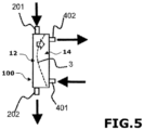
- the dialyzer 100 is in the form of an enclosure which includes a body fluid passage zone 12, called the blood compartment, which has a body fluid inlet 201 and a body fluid outlet 202.
- the enclosure also includes a dialysate passage zone 14, also called the dialysate compartment, which has a dialysate inlet 401 and a dialysate outlet 402.
- the dialysate inlet 401 and the dialysate outlet 402 are intended to be connected by connection systems 800, 900 presented below to, respectively, a dialysate supply line 52 and a dialysate discharge line 62 (see Figure 7 ).
- Dialysate is a liquid well known to those skilled in the art whose composition is similar to physiological serum. Dialysate comprises water of sufficient mineral and bacteriological quality. This water is added to a concentrate, in the form of mineral salt powder or liquid concentrate, to produce the required dialysate.
- physiological serum is composed of a mixture of water and sodium chloride.
- the dialysate is generally composed of physiological serum to which glucose and ions such as potassium, magnesium, calcium, and possibly lactate and/or bicarbonate are added, depending on the patient's needs.
- the dialysate used is sterile, pyrogen-free dialysate.
- the dialysate has been sterilized, for example, in an autoclave.
- This dialysate can be made from purified water and salt.
- the dialysate circulation passes through the dialysate compartment 14, generally in the opposite direction to the blood circulation in the other blood compartment 12.
- the dialysate generally circulates in an open circuit.
- a partial regeneration loop of clean dialysate can be provided from the toxin-laden dialysate.
- the enclosure also includes a membrane system 3 to allow an exchange of elements (substances, molecules) between the body fluid present in the body fluid passage zone 12 and the dialysate present in the dialysate passage zone 14.
- the dialyzer 100 can be schematized in the form of an enclosure housing a dialysis membrane 3 which separates the enclosure into a blood compartment, corresponding to the zone of passage of the body fluid 12 and into a dialysate compartment, corresponding to the zone of passage of dialysate 14.
- the semi-permeable dialysis membrane system 3 is designed to allow a fraction of the blood volume to pass through when the difference between the local pressure in the blood compartment 12 and the local pressure in the dialysate compartment 14 is greater than a given value. This pressure difference is called transmembrane pressure.
- the membrane system is designed in such a way that only the smallest molecules can pass through the holes or pores of the membrane system, namely water, mineral salts and molecules of small to medium molecular weight.
- the membrane system 3 may comprise a membrane designed such that, when the difference between the pressure exerted on at least one portion of the membrane on the side of the blood compartment 12 and the pressure exerted on said portion of the membrane on the side of the dialysate compartment 14, is greater than a given threshold value, said portion of the membrane allows an aqueous fraction of the blood to pass into the dialysate compartment 14, according to a convective phenomenon called ultrafiltration.
- said membrane 3 is designed such that, when the difference between the pressure, which is exerted on said portion of the membrane 3 on the side of the dialysate compartment 14, and the pressure, which is exerted on said portion of the membrane on the side of the blood compartment 12, is greater than a given threshold value, said portion of the membrane allows the dialysate to pass into the blood compartment 12, according to a phenomenon called retrofiltration.
- the dialysis membrane system can be made in the form of capillary fibers, with blood circulating inside the fibers and dialysate outside.
- the blood inlet 201 is connected to an arterial line L1, one end of which is, for carrying out a dialysis session, connected to a fistula of the patient, in order to be able to extract the blood from the body of the patient to be treated.
- the blood outlet 202 is connected to a venous line L2, one end of which is connected to a vein of the patient to reintroduce the blood into the body of the patient after treatment.
- the term "line” means a tube possibly comprising several branches or portions and through which a liquid can circulate. According to a particular aspect, these lines can be linked to each other so that one cannot be removed without the other.
- the arterial line L1 is also equipped with a blood pump Psg, and a pressure sensor Pa, also called an arterial pressure sensor.
- the venous line L2 comprises a pressure sensor Pv, also called a venous pressure sensor, a bubble trap PB, and an air detector DA.
- the pressure sensor Pv is connected to the bubble trap PB.
- said venous line L2 also comprises an anticoagulant injection system, such as a heparin pump PH.
- the L1 arterial line, the L2 venous line and the 12 blood compartment form the blood circuit of the machine.
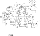
- the machine also comprises a dialysate supply system 5 which comprises a dialysate supply line 52 which is connected to the inlet 401 of the dialysate compartment 14, and a dialysate evacuation system 6 which comprises an evacuation line 62 connected to the outlet 402 of the dialysate compartment 14.
- a dialysate supply system 5 which comprises a dialysate supply line 52 which is connected to the inlet 401 of the dialysate compartment 14, and a dialysate evacuation system 6 which comprises an evacuation line 62 connected to the outlet 402 of the dialysate compartment 14.
- Said dialysate supply system 5, the dialysate compartment 14, and said dialysate discharge system 6 form the dialysate circuit.
- the dialysate supply line 52 is connected to the inlet 401 of the dialysate passage zone 14 by a connection system 800.
- connection system 800 comprises a first connection device 810 fixed, for example by gluing, to the supply line 52, and a second connection device 820 connectable to the first connection device 810, to allow fluid communication through the first connection device and the second connection device.
- the second connection device 820 is disconnectable from the first connection device 810.
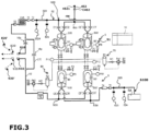
- the second connection device 820 connected to the first connection device 810, can thus be connected to the dialysate inlet 401 of the dialyzer 100 for a first dialysis session, then be disconnected from the first connection device 810 which remains fixed on the supply line, for example at the same time as the dialyzer is removed (or separately), to be able to replace this second connection device 820, with a new second connection device 820' as illustrated in Figures 3 , 4 , 12 And 13 .
- This new second connection device 820' considered clean or sterile, can then be connected by one end to the first connection device 810 and by its other end to the dialysate inlet 401 of a new dialyzer 100' as illustrated in Figure 4 .
- the second connecting device 820 which is removably connectable to the first connecting device 810, comprises a female Hansen type connector 822 and a female Luer Lock type connector 821. These two connectors 821, 822 are connected to each other by tubing.
- the Hansen type connectors correspond to the NF EN ISO 8637 standard.
- the first connecting device 810 fixed to the supply line 52 comprises a male Luer Lock type connector 811 connectable to the connector 821, and a female Luer Lock type connector 801 at the other side connected to the line 52.
- the Luer Lock type connectors correspond to the NF EN ISO 594 standard.
- the connector 811 comprises a tubular element 812 capable of being engaged in the opening of the first connector 821 of the second connecting device 820, to be in fluid communication with the opening of the first connector 821 of the second connecting device 820, and a peripheral wall 813 which extends around and at a distance from the tubular element 812 to define an annular space for insertion of the peripheral wall of the first connector 821 of the second connecting device 820 presented below.
- the peripheral wall 813 is tapped to cooperate with a thread 821a of the first connector 821 formed on at least a portion of the external face of its peripheral wall.
- the first connector 821 of the second connecting device 820 is in the form of a tubular element, preferably straight, which defines an opening opening at one end of said second connecting device 820 to receive said tubular element 812 of the connector 811.
- the first connector 821 is thus able to cooperate with the connector 811 of the first connecting device 810 by engagement of the peripheral wall of the first connector 821 between the tubular element 812 and the peripheral wall 813 of the connector 811 of the first connecting device 810.
- the second connector 822 of the second connecting device 820 may be in the form of a tubular element of circular section, preferably of diameter greater than that of the first connector 821.
- the second connector 822 is connectable to the dialysate inlet 401 of the dialyzer.
- the second connecting device 820 has lateral fins 828 facilitating the gripping of the second connecting device 820 to disconnect it.
- the plug 824' comprises a stud 824a adapted to be engaged in the opening of the first connector 821' of the second connecting device 820', and a peripheral wall 824b which extends around and away from the stud 824a to define an annular space for insertion of the peripheral wall of the first connector 821'.
- the peripheral wall 824b is preferably tapped to cooperate with the thread 821a'.
- the second connector 822 of the second connecting device 820 intended to be connected to the inlet 401 of the dialyzer 100, is provided with a cap 829 making it possible to close the opening of the second connector 822, while being removable to release the opening of the second connector 822.
- the cap 829 remains attached to the second connector 822 by a fastening element such as a wire, to prevent it from falling or being lost.
- such a system makes it possible to limit the risk of bacteriological contamination/proliferation, during a period of stopping the use of the machine (or putting it on standby) between a first session and a second dialysis session, since the new second connection device 820' can be connected and left in the position of closing the cap 829 during the period of stopping the use of the machine (or putting it on standby) between the first session and the second dialysis session.
- the supply system 5 also comprises a dialysate delivery system 51 connected to the supply line 52. Said dialysate supply system 5 makes it possible to deliver dialysate into the dialysate compartment 14 via the supply line 52.
- said delivery system 51 comprises at least one flexible bag 50, called a ventricle bag, intended to contain dialysate.
- Said system 51 may comprise several bags as in the example illustrated in the figures.
- said dialysate supply system 5 comprises an additional ventricle bag 50' which is mounted as a bypass of the portion of the supply line 52 to which said ventricle bag 50 is connected.
- each ventricle bag of the system 51 is intended to contain dialysate and is connected to said supply line 52.
- Each ventricle pocket 50, 50' is housed in a substantially sealed enclosure 500, 500' which can be pressurized, and possibly under vacuum. Each ventricle pocket 50, 50' can thus be pressurized by pressurizing means 70 and, possibly, under vacuum by a vacuum generator 80.
- Said pressurizing means 70 comprise a device for injecting pressurized gas, such as an air compressor or a compressed gas cylinder, capable of injecting pressurized gas into the sealed enclosure 500, 500' in which the ventricle pocket 50, 50' is housed.
- Said enclosure has an outlet whose opening can be controlled by a solenoid valve to reduce the pressure in the enclosure.
- the two ventricle pockets 50, 50' are capable of being pressurized/depressurized independently of one another.
- each ventricle bag 50, 50' is also provided with a downstream closing/opening member C1, C1' of the supply line which, in the open state, allows the flow of dialysate from the corresponding bag 50, 50' towards the inlet 401 of the dialysate compartment, under the effect of pressure applied to said ventricle bag by the corresponding means 70, and in the closed state, prevents said flow of dialysate.
- Each downstream closing/opening member C1, C1' of the supply line is located between the corresponding pocket 50, 50' and the output node NS5 connecting the two pockets 50, 50'.
- Each ventricle pocket 50, 50' is also provided with an upstream closing/opening member C2, C2' which makes it possible to authorize or not the supply of said ventricle pocket 50, 50' by a supply source 40.
- the supply source 40 may comprise a plurality of feeder pockets.
- connection system 450 for connecting a dialysate supply source to the dialysate delivery system 51 is described below.
- each portion of the dialysate supply line 52 at which an upstream C2, C2' or downstream C1, C1' closing/opening member is located is flexible.
- Each of said members C2, C2', C1, C1' of closing/opening is formed by a controllable clamp for, on the one hand, clamping from the outside the wall of said flexible portion of the supply line 52 so as to close this portion, and, on the other hand, to leave open said flexible portion of said supply line 52.
- the presence of the two ventricle pockets and the alternating clamping system formed by the organs C1 to C2' makes it possible to successively and alternately load the ventricle pockets from the power source 40. This makes it possible to continuously supply the dialysate supply line from one of the ventricle pockets.
- the depressurization of the enclosure of a ventricle bag 50 or 50' using the vacuum generator 80 makes it possible, in the open state of the upstream opening/closing member C2 or C2', and in the closed state of the corresponding downstream opening/closing member C1 or C1', to suck up the dialysate contained in the supply source 40 or 40' to fill said ventricle bag 50 or 50'.
- control unit 10 controls the opening of the downstream member C1 or C1' of one of the ventricle bags 50 or 50' and the closing of the corresponding upstream member C2 or C2'.
- the use of two ventricle bags mounted in parallel makes it possible to recharge one while the other is in use.
- the dialysate supply line 52 comprises a passage restriction 520 to create a pressure drop and to allow the pressure applied to the ventricle bag 50 or 50' to be regulated as a function of the pressure difference measured at the terminals of said restriction.
- said line 52 is provided with means for measuring the pressure difference between the inlet and the outlet of said passage restriction 520.
- This restriction 520 may be formed at least in part from a calibrated tube of constant section which forms a constriction over a predetermined length. Said passage restriction 520 is located between the bags 50, 50' and the inlet 401 of the dialysate compartment 14.
- the NS5 connection of the delivery system 51 to said supply line 52 is located upstream of the passage restriction 520.
- Said pressurizing means advantageously maintain a pressure on the ventricle bag 50 or 50' which is sufficient to cause the flow of the dialysate.
- the supply line is calibrated so that, for a determined pressure applied to the ventricle bag 50 or 50', the flow rate of dialysate in said line has a substantially constant value.
- Such a system formed by a pressure drop tube and means for measuring the pressure difference across the restriction makes it possible in particular to determine the flow rate of dialysate which circulates in said supply line and which enters the dialysate compartment. Thanks to the flow rate of dialysate thus measured, the control unit 10 can regulate the pressure applied to the ventricle bag 50 or 50' to obtain the desired flow rate of dialysate entering the dialysate compartment and precisely and reliably maintain this flow rate at a given value for a given time.
- Said means for measuring the pressure difference across the restriction 520 of the supply line 52 may comprise two pressure tapping orifices provided in the peripheral wall of said line 52, one upstream and the other downstream of said restriction 520.
- Each pressure tapping orifice is associated with a pressure sensor 523, 524.
- Each pressure sensor 523, 524 is arranged relative to the corresponding pressure tapping orifice so as to measure the pressure in the supply line 52 at said pressure tapping orifice while being spaced from said orifice so as not to be in contact with the dialysate circulating in the line 52, 62.
- the pressure sensors 523, 524 may be configured as described in the international application WO2013050689 .
- the pressure measurement in the arterial line L1 and the venous line L2 is carried out in the same way as for the pressure measurement at the terminals of the restriction 520. It can thus be provided that the pressure sensor Pa and the pressure sensor Pv are fixed in a part of the frame at a distance from a pressure orifice provided in the corresponding line L1, L2. According to a particular aspect, the pressure sensors Pa and Pv measure the pressure in the corresponding line L1, L2 without risk of contamination.
- the dialysate evacuation system 6 comprises a dialysate evacuation line 62 which is connected to the outlet 402 of the dialysate compartment 14 as detailed below.
- the dialysate evacuation system 6 also comprises a pipe 6100 intended to be connected, for example at the tip 6101 (which can be closed by a cap 6109), to a recovery container or to a sewage system Egt.
- connection system 900 includes a first connection device 910 attached to the discharge line 62, and a second connection device 920 connectable to the first connection device 910, to enable fluid communication through the first connection device and the second connection device.
- the second connection device 920 is disconnectable from the first connection device 910.
- the second connection device 920 connected to the first connection device 910, can thus be connected to the dialysate outlet 402 of the dialyzer 100 for a first dialysis session, then be disconnected from the first connection device 910, for example at the same time as the dialyzer is removed (or separately), in order to be able to replace this second connection device 920 with a new second connection device 920'.
- This new second connection device 920' considered clean or sterile, can then be connected by one end to the first connection device 910 and by its other end to the dialysate outlet 402 of the new dialyzer 100'.
- the second connecting device 920 which is removably connectable to the first connecting device 910, comprises a female Hansen-type connector 922 and a female Luer Lock-type connector 921. These two connectors 921, 922 are connected to each other by tubing.
- the connectors Hansen type connectors correspond to the NF EN ISO 8637 standard.
- the first connection device 910 fixed to the evacuation line 62 comprises a male Lueur Lock type connector 911 connectable to the connector 921, and a female Lueur Lock type connector 901 at the other side connected to the line 52.
- the Lueur Lock type connectors correspond to the NF EN ISO 594 standard.
- connection system 900 comprises elements identical to those of the connection system 800 presented above.
- the connector 911 comprises a tubular element 912 adapted to be engaged in the opening of the first connector 921 of the second connecting device 920, to be in fluid communication with the opening of the first connector 921 of the second connecting device 920, and a peripheral wall 913 which extends around and at a distance from the tubular element 912 to define an annular space for insertion of the peripheral wall of the first connector 921 of the second connecting device 920 presented below.
- the first connector 921 is able to cooperate with the connector 911 of the first connection device 910 by engagement of the peripheral wall of the first connector 921 between the tubular element 912 and the peripheral wall 913 of the connector 911.
- the second connector 922 of the second connecting device 920 may be in the form of a tubular element of circular section, preferably of diameter greater than that of the first connector 921.
- the second connector 922 is connectable to the dialysate outlet 402 of the dialyzer.
- the second connection device 920 comprises a cap which makes it possible to close the opening of the first connector 921 of the second connection device 920, while being removable to release the opening of the first connector 921 of the second connection device 920.
- This cap is visible and referenced 924' at the Figure 12 for the second 920' connection device.
- the plug 924' comprises a stud 924a capable of being engaged in the opening of the first connector 921' of the second connecting device 920', and a peripheral wall 924b which extends around and at a distance from the stud 924a to define an annular space for insertion of the peripheral wall of the first connector 921', and preferably tapped to cooperate with the thread 921a.
- the 929' cap of the second 920' connection device can be left closed during the shutdown or standby period between two dialysis sessions, before connecting the new 100' dialyzer.
- the 900 connection system makes it possible to limit the risk of bacteriological contamination/proliferation at the level of the corresponding line 62, between a first session and a second session.
- Said machine comprises a system, preferably of the clamp type, for opening/closing the dialysate evacuation line 62.
- the opening/closing system authorizes, in the open state, the circulation in said evacuation line 62 of the dialysate present at the outlet 402 of the dialysate compartment 14. to fill one of the discharge bags 60 or 60', and prevents, in the closed state, the circulation in said discharge line 62 of the dialysate so that, for sufficient pressure in the dialysate compartment, said dialysate passes through the membrane 3 into the blood compartment.
- said dialysate evacuation system 6 comprises at least one discharge bag 60, preferably flexible, having an inlet and an outlet connected to the dialysate evacuation line 62.
- Said opening/closing system comprises an upstream opening/closing member C5 located between the outlet 402 of the dialysate compartment 14 and said discharge bag 60.
- a closing/opening member may also be provided on the line 62.
- said dialysate evacuation system 6 comprises at least one other discharge bag 60' mounted as a bypass from said discharge bag 60.
- the discharge bag 60 and the discharge bag 60' are located on two branches of the evacuation line 62.
- the evacuation line 62 separates, upstream of the discharge bags 60, 60', into two parallel branches, one provided with the discharge bag 60 and the other with the discharge bag 60'. These two branches connect to each other downstream of the bags 60, 60' and upstream of the section restriction 620 as detailed below.
- Said opening/closing system comprises another upstream opening/closing member C5' located between said other discharge pocket 60' and the inlet node NE6 for connecting the discharge pockets 60, 60'.
- each discharge pocket 60, 60' is provided with a downstream closing/opening member C6, C6' located between the corresponding discharge pocket 60, 60' and the outlet node NS6 for connecting the discharge pockets 60, 60'.
- Each portion of the dialysate evacuation line 62 at which an upstream C5, C5' or downstream C6, C6' closing/opening member is located is flexible.
- Each of said upstream C5, C5' or downstream C6, C6' closing/opening members of the dialysate evacuation line 62 is formed by a controllable clamp for, on the one hand, clamping the wall of said flexible portion of the evacuation line 62 so as to close this portion, and, on the other hand, to leave open said flexible portion of said evacuation line 62.
- Such a set of upstream members C5, C5' and downstream members C6, C6' for closing/opening associated with the discharge pockets 60, 60' allows, in the open state of the upstream member C5, respectively C5', and closed state of the downstream member C6, respectively C6', to fill the discharge pocket 60, respectively 60', and, in the closed state of the upstream member C5, respectively C5', and open state of the downstream member C6, respectively C6', to empty said discharge pocket 60, respectively 60'.
- the evacuation line 62 is considered to be open when the dialysate can circulate through said line to fill said or one of said bags.
- the means for discharging the dialysate and the liquid present in the discharge bag 60 or 60' may be formed by gravity if the configuration of the discharge bag lends itself to it and/or by pressurizing means 70, preferably common to those used for pressurizing the ventricle bags 50, 50'.
- said or each bag 60, 60' is housed in a substantially sealed enclosure 600, 600' capable of being pressurized by said pressurizing means 70.
- Said enclosure has an outlet whose opening can be controlled by a solenoid valve to reduce the pressure in the enclosure.
- each enclosure 600, 600' which houses a discharge bag 60, 60' is connected to a vacuum generator 80.
- the vacuum generator 80 and/or the pressurizing means 70 make it possible to apply pressure or depression to the discharge bag 60 or 60', so as to adjust the average pressure in the dialysate compartment 14, for example during an ultrafiltration phase.
- the downstream member C6 or C6' of the discharge bag 60 or 60' which is used to adjust the average pressure in the dialysate compartment 14 is closed while the corresponding upstream member C5 or C5' is open.
- Said vacuum generator 80 may be common for depressurizing the enclosures of the dialysate supply system 5 and for depressurizing the enclosures of the evacuation system 6.
- Said machine comprises means for determining the quantity of dialysate and liquid recovered in the discharge bag 60 or 60' which empties.
- said means for determining the quantity of dialysate and liquid recovered in the discharge bag(s) 60, 60' comprise a passage restriction 620, arranged in the dialysate discharge line 62 and located downstream of said discharge bags 60, 60', and means for measuring the pressure difference across said passage restriction 620.
- Said means for measuring the pressure difference across the restriction 620 of the discharge line 62 may be similar to those associated with the restriction 520 of the supply line 52.
- said means for measuring the pressure difference across the restriction 620 of the evacuation line 62 may comprise two pressure tapping orifices provided in the peripheral wall of said line 62, one upstream and the other downstream of said restriction 620.
- each pressure tapping orifice is associated with a pressure sensor arranged so as to measure the pressure in the line 62 at said orifice while being spaced from said orifice so as not to be in contact with the dialysate circulating in the line 62.
- each pressure sensor 623, 624 is mounted in a cavity of the machine frame using a hollow support part which is intended to be coupled to the conduit 621, 622 connected to the corresponding pressure tapping orifice.
- the pressure sensors 623, 624 associated with said restriction 620 make it possible to determine the pressure difference across the restriction 620 and thus the flow rate of dialysate and liquid discharged from the discharge bag 60. or 60', which makes it possible to determine, by measuring the corresponding flow time, the quantity of dialysate and liquid recovered in said discharge bag 60 or 60'.
- the dialysate supply source used for a given dialysis session is preferably one or a set of feed bags of larger volume, for example 5L, than that, for example 150 ml, of said ventricle bag 50, 50'.
- each supply source 40, 40' comprises a plurality of bags 41, called feeder bags, and a connection device 49, called an interconnection octopus, which comprises a plurality of pipes for connecting the feeder bags to each other at the level of tips 411, preferably using quick connectors, for example Luer Lock type connectors.
- each dialysate supply source 40 or 40' may be housed in a tiered support structure 140.
- An example of a tiered support structure is described in the international application WO2014001680 .
- each feed pocket 41 of the power source is positioned in a stage of the support structure 140.
- the power source 40 comprises a conduit 414 provided with a connector (or fitting) 415 which can be connected to and disconnected from the first section 451.
- the power source 40' comprises a conduit 414' provided with a connector 415' (preferably identical or similar to the connector 415) which, in the state removed from the first section 451, can be connected to and disconnected from the second section 452 of the connection system 450 presented below.
- the pipe 414 is located at the lowest feeder bag 41 in the positioned state of the feeder bags in the support structure 140.
- the connector 415 of the power source 40 is connected to the first section 451.
- the connector 415 is non-removable, for example welded, to the pipe 414 of the power source 40.
- Said connector 415' is also disconnectable from the second section 452 and is preferably secured in a non-removable manner to the pipe 414' of the power source 40'.
- the machine comprises a connection system 450 between a dialysate supply source 40 and the dialysate supply line 52, in particular at a connector 456 ( Figure 14 ) which communicates with the inlet 511 of the dialysate delivery system 51, to supply dialysate to the bags of the dialysate delivery system 51.
- a connection system 450 between a dialysate supply source 40 and the dialysate supply line 52, in particular at a connector 456 ( Figure 14 ) which communicates with the inlet 511 of the dialysate delivery system 51, to supply dialysate to the bags of the dialysate delivery system 51.
- the dialysate supply source used for a first dialysis session is referenced 40 and that, distinct from the supply source 40, used for a second dialysis session is referenced 40'.
- the dialysate supply source used for a given dialysis session is preferably one or a set of feed bags of larger volume, for example 5L, than that, for example 150 ml, of said ventricle bag 50, 50'.
- the connection system 450 comprises a first section 451 which comprises a conduit 4510 having an end capable of being connected by a connector 4511, preferably a Luer Lock type connector, for example male, to a corresponding connector 415, for example female, with which a conduit 414 of the first dialysate supply source 40 is provided.
- the Luer Lock type connector corresponds to the NF EN ISO 594 standard.
- the conduit 4510 of the first section 451 comprises at the other end a connector 4512 configured to be connected to a connector of a second section 452 of the connection system 450.
- the first section 451 is provided with a clamp system C451, initially in the open state and which can be actuated to close on the conduit 4510, by degrading the conduit 4510 and/or by being locked in the closed position.
- the system C451 is also called a tamper-evident closing member. The use of such a tamper-evident closing member C451 makes it possible to ensure that the first section 451, in particular the corresponding conduit 4510, is not reused.
- connection system 450 also comprises a second section 452 which comprises a conduit 4520 having an end capable of being connected to a second dialysate supply source 40'.
- said end of the second section 452 is provided with a connector 4521, for example of the male Luer Lock type.
- the other end of the second section 452 is connected to a connector 456 which is in fluid communication with the inlet 511 of the delivery system 51.
- the second section 452 is equipped with a clamp system C452 for opening/closing the second section 452.
- the dialysate supply source 40 is connected to the first section 451 of the connection system 450, by its pipe 414 provided with a connector adapted to be connected to the connector 4511 of the first section 451.
- the connector of the pipe 414 is preferably a female Luer Lock connector, for example a connector of the type of the connector referenced 4512, 821 or 921.
- the clamp system C451 is left in the open state, as is the clamp system C452 to allow the dialysate coming from said supply source to supply the delivery system 51 which is connected to the supply line 52.
- the dialysate can thus flow from the supply source 40 to the delivery system 51 by passing through the first section 451 and the second section 452.
- the pipes 4510, 4520 of the connection system 450 are in the form of flexible pipes so that they can be pinched.
- the pipes 4510, 4520 have, in the unpinched state (or in the uncrushed state), a cross-section of constant diameter (external and internal) over their entire length.
- the pipes 4510, 4520 do not have intermediate reserves or pockets (for example of liquid) between their ends.
- the supply inlet 511 of the dialysate delivery system 51 may correspond to a connecting node between the inlets of the bags 50, 50'.
- the C451 system is closed by the operator (the user or a third party) to render the first section 451 unusable, and the first section 451 is disconnected from the second section 452 (disconnection of connector 4512 from connector 4521) to be discarded.
- the second section 452 is connected to another dialysate supply source 40' whose characteristics may be similar or identical to those of the dialysate supply source 40.
- the power source 40 is removed with the section 452 to which the power source 40 was connected and the power source 40' is connected to the next section 451 of the connection system 450.
- the 450 connection system can have a greater number of successive sections so as to make it possible to achieve as many of dialysis sessions than sections by removing the used section after each dialysis session in order to be able to use the next section for the next dialysis session.
- the second section is itself formed of a plurality of sections (sub-sections) connected in series.
- each power source 40 or 40' comprises a plurality of pockets 41, called feeder pockets.
- each section 451 or 452 of the connection system 450 can thus be, selectively, connected to a pipe 414 of the lowest feeder pocket 41 in the positioned state of the feeder pockets in the support structure 140.
- connection system 450 and the flexible bag dialysate delivery system 51 avoids having to open the enclosures 500, 500', and therefore access the cassette, not only during a dialysis session, but also between two successive sessions as long as there remains an unused section of the connection system. Indeed, during a session with the power source 40 and then during the following session with the power source 40', the cassette and therefore the ventricle bags can be left in the machine without having to be replaced.
- a part of the machine is in the form of a cassette 9 having a body 900.
- the cassette 9 is a cassette removable relative to the frame (or chassis) of the machine which is intended to be inserted into a housing of said frame.
- Said cassette 9 comprises in particular the said bag(s) 50, 50', a body 900, and the supply line 52.
- the cassette 9 also comprises the dialysate evacuation line 62, and the discharge bag(s) 60, 60' of the evacuation system.
- said cassette 9 notably comprises the dialysate lines 52, 62, and each bag 50, 50', 60, 60'.
- the cassette can understand the connection system 450 of the dialysate supply source 40, 40' to the delivery system 51 and/or the connection system 800, 900 to the dialyzer.
- the pressure sensors 523, 524, 623, 624, shown in Figures 2 to 4 are fixed to the frame of the machine.
- the pressure tapping conduits are in pneumatic communication with the pressure sensors.
- pneumatic communication is meant that the sensor and the corresponding pressure tapping conduit are arranged relative to each other in such a way that the sensor is able to measure the pressure prevailing in said conduit, and therefore the pressure prevailing in the line at the level where the corresponding pressure tapping orifice is provided.
- said machine also comprises a control unit 10, such as a programmable controller.
- the control unit can be configured to perform dialysis steps, as described in international applications WO2013050689A1 Or WO2019150058A2 .
- a dialysis session comprises, in addition to priming and restitution phases, a dialysis phase which may comprise a plurality of ultrafiltration steps alternating with backfiltration steps.
- a dialysis phase which may comprise a plurality of ultrafiltration steps alternating with backfiltration steps.
- An example of operation of the machine during a dialysis session with a plurality of ultrafiltration steps alternating with backfiltration steps is described in the international application WO2013050689A1 Or WO2019150058A2 .
- the dialysis phase generally includes an exchange phase between the blood compartment and the dialysate compartment, for example by osmosis, and may not include a backfiltration phase and/or an ultrafiltration phase.
- the control unit 10 controls in particular the means for pressurizing the bags 50, 50' and the clamp systems C1, C2; C1', C2' and C5, C6; C5', C6' for closing/opening the supply system 5 and the evacuation system 6.
- the priming phase corresponds to the arrival of the blood in the blood compartment of the dialyzer.
- the control unit controls the blood pump Psg.
- the dialysis session ends with a restitution phase during which the blood present in the blood circuit (venous line, arterial line, and patient's blood compartment) is returned to the patient.
- the control unit also controls the Psg blood pump, a physiological saline bag being connected to the L1 line to allow the blood to be returned without the risk of introducing air.
- control unit 10 is further configured to implement a method of rinsing and eliminating air from the extracorporeal circuit of the dialysis machine, for example by executing rinsing and/or air elimination steps, as described in the application FR 2001604, filed on February 18, 2020 and not yet published.
- Said control unit 10 is in the form of an electronic and computer system which comprises for example a processor, such as a microprocessor, a working memory and a data memory. Said control unit may be in the form of a microcontroller.
- control unit or its modules can be implemented by computer instruction sets or modules stored in a memory for their execution by a processor or controller or can be implemented by dedicated electronic components or FPGA or ASIC type components. It is also possible to combine computer parts and electronic parts.
- the unit or means or modules of said unit are configured to perform a given operation, this means that the unit comprises computer instructions and the corresponding execution means which enable said operation to be performed and/or that the unit comprises corresponding electronic components.
- Said control unit also has a data input interface. It can be provided that said interface allows data relating to the patient and/or the machine's consumables to be entered.
- the dialysis machine is also equipped with conventional components to ensure reliable and efficient treatment of the bodily fluid to be treated, in particular a blood leak detector FS arranged in the evacuation line 62.
- the control unit 10 is configured to allow the flow meters to be calibrated relative to each other.
- Each enclosure 500, 500' is equipped with means for heating or preheating the enclosure.
- Each enclosure 500, 500', 600, 600' is also equipped with a vent valve V2, V5, V8, V11 associated with an air filter F1, F2, F3, F4, and a pressure sensor P7, P8, P9 and P10.
- the pressurizing means 70 include the following elements: a compressed air tank R1, a pressure sensor P11 of the tank R1, a compressor Pa1, a check valve for compressed air Ar1, and an air filter and silencer for compressed air Si1.
- the 80 vacuum generator includes an air vacuum reservoir R2, a pressure sensor P12 of the reservoir R2, a vacuum pump Pa2, a check valve for the air vacuum Ar2 and an air filter and silencer for the air vacuum Si2.
- the supply line 52 is also provided with means for heating Ch3 the dialysate associated with means for measuring temperature T1, T2, T3.
- the discharge line 62 is provided with means for measuring temperature T4, T5 downstream of the bags 60, 60'.
- the venous line L2 also comprises a CV closing/opening member, such as a clamp.
- the machine may comprise a bypass line L10, as well as one or more associated Vbp closing/opening members.
- the bypass line L10 may be used to prime and calibrate the dialysate circuit, and to prevent defective dialysate from being injected into the dialyzer, for example due to a temperature problem.
- the implementation of a dialysis session with a dialysis machine as described above comprises the steps described below.
- the order of certain steps may be reversed and the method may comprise other additional steps between two described steps.
- the method described below allows the prolonged use of a cassette after the completion of a first dialysis session for the execution of a second dialysis session with the same cassette, with a reduced risk of contamination during the intervention of the operator to change the dialyzer and/or change the dialysate supply source.
- the user opens a door of the dialysis machine to insert the cassette 9 into a corresponding housing (for example visible at Figure 7 ).
- the presence of the 829 and 929 caps limits the risk of contamination of the 820 and 920 connectors when the cassette is removed from its packaging for the first session and before installation in the machine and before connection to the dialyzer.
- the user opens the caps 829 and 929 and connects the supply line 52 to the inlet 401 of the dialysate passage zone 14 of the dialyzer 100 with the connection system 800 and connects the evacuation line 62 to the outlet 402 of the dialysate passage zone 14 of the dialyzer 100 with the connection system 900 (step 1610).
- the clamp systems C451, C452 are in the open position, so that the lines 451, 452 are not clamped.
- the user places feeder bags 41 of dialysate from the supply source 40 in the support structure 140.
- the user connects the feeder bags 41 to each other using the interconnecting octopus 49.
- the user installs and connects a physiological serum bag on the L1 line upstream of the Psg pump.
- the user connects the L2 venous and L1 arterial lines of the extracorporeal circuit to the dialyzer 100.
- the user connects if necessary the first section 451 of the connection system 450 to the power source 40 (step 1620).
- the connection system 450 is provided (delivered) in a configuration where the first section 451 and the second section 452 are already connected to each other, the second section 452 also being connected to the delivery system 51.
- the clamp system C452 of the second section is left open to allow the dialysate from the power source 40 to supply the delivery system 51 via the sections 451 and 452 of the connection system. Note that the clamp system C451 is also left open until the first dialysis session is completed.
- the connector 4511 of the first section 451 is connected to the connector 415 of the first dialysate supply source 40, while the second section 452 is in fluid communication with the first section 451 via the connectors 4512, 4521.
- the clamp systems C451, C452 are in the open position.
- the control unit acquires, for example, by entering data into a data interface and/or by reading data from a memory relating to the consumables or their batch, such as identification data of the dialysate supply source, the dialyzer, the extracorporeal circuit, and the cassette.
- the user can make settings using the input interface, including entering "dry” and actual weight data to enable the control unit to determine the amount of excess aqueous fraction to be removed from the body fluid.
- the control unit can command the execution of a first dialysis session comprising priming and dialysis sequences and restitution.
- the priming sequence may be preceded by a step of rinsing the consumables by circulating dialysate in the dialysate circuit, particularly in the cassette.
- physiological serum is circulated in the extracorporeal circuit (blood lines and blood compartment) to rinse this extracorporeal circuit.
- the patient can then connect to the L1 line.
- control unit controls the purging of the dialysate present in the supply system 5 and the evacuation system 6.
- the machine may then be put into sleep mode potentially intermittently.
- the user removes certain consumable items from the machine, such as arterial L1 and venous L2 lines; and the dialyzer.
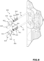
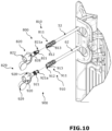
- the cassette 9 remains in the machine except for the connectors 820 and 920 which the operator disconnects from the supply line 52 and the discharge line 62 relative to the dialyzer 100, as illustrated in Figure 10 , to replace them with new fittings 820' and 920' which are connected respectively to fittings 810 and 910 as shown in Figures 3 , 4 And 12 , the caps 829' and 929' being initially in the closed position.
- the user also removes the first power source 40 (step 1630).
- the tamper-evident C451 clamp system is closed after the first session, before or after removal of the power source.
- the end of the connection system formed by the connector 4511 is closed by a cap which may be a cap 4519 initially present on this connector 4511, and which has previously been removed to be able to connect the first power source 40, before carrying out the first dialysis session.
- a cap which may be a cap 4519 initially present on this connector 4511, and which has previously been removed to be able to connect the first power source 40, before carrying out the first dialysis session.
- the first section 451 of the connection system 450 is removed, as illustrated in Figure 11 , which leaves connector 4521 of the second section 452 free to be able to connect connector 415' of another power source 40'.
- the removal of the first section 451 is preferably carried out just before the connection of the second section 452 of the connection system 450 to the second dialysate supply source 40'.
- the second section 452 of the connection system 450 is connected to the second dialysate supply source 40' (step 1650).
- the feeder bags of the supply source 40' are connected to each other using an interconnecting octopus.
- the user opens the clamp system C452 (which may have been previously closed after the first dialysis session) to release the fluid communication within the second branch 452.
- New L2' venous and L1' arterial lines are connected to a new 100' dialyzer.
- the user installs and connects a new saline bag.
- the caps 829', 929' of the new connectors 820', 920' are then opened, as shown in Figure 13 , to connect the supply line 52 to the inlet 401 of the dialysate passage zone 14 of a new dialyzer 100' and the discharge line 62 to the outlet 402 of the dialysate passage zone 14 of the new dialyzer 100'.
- the user can enter parameters using the input interface for the second dialysis session.
- control unit 10 can command the execution of a second dialysis session comprising priming, dialysis and restitution sequences.
- the 829' and 929' caps present on parts 820' and 920', available for the second session, allow the latter to be protected from contamination when they are removed from their individual packaging before the start of the second session.
Landscapes
- Health & Medical Sciences (AREA)
- Heart & Thoracic Surgery (AREA)
- Animal Behavior & Ethology (AREA)
- General Health & Medical Sciences (AREA)
- Anesthesiology (AREA)
- Biomedical Technology (AREA)
- Hematology (AREA)
- Life Sciences & Earth Sciences (AREA)
- Veterinary Medicine (AREA)
- Engineering & Computer Science (AREA)
- Public Health (AREA)
- Urology & Nephrology (AREA)
- Pulmonology (AREA)
- Vascular Medicine (AREA)
- Emergency Medicine (AREA)
- External Artificial Organs (AREA)
Claims (13)
- Dialysemaschine, die gestattet, eine Körperflüssigkeit wie Blut oder Plasma zu behandeln, wobei die Dialysemaschine aufweist:- einen Dialysator (100, 100'), umfassend ein Gehäuse, das einen Körperflüssigkeitsdurchgangsbereich (12) einschließt, der einen Körperflüssigkeitseinlass (201) und einen Körperflüssigkeitsauslass (202) aufweist, und einen Dialysatdurchgangsbereich (14), der einen Dialysateinlass (401) und einen Dialysatauslass (402) aufweist, und ein Membransystem (3) zwischen dem Körperflüssigkeitsdurchgangsbereich und dem Dialysatdurchgangsbereich (14);- ein Dialysatabgabesystem (51),- ein Verbindungssystem (450), das gestattet, eine Dialysatversorgungsquelle (40) mit dem Dialysatabgabesystem (51) zu verbinden, wobei das Verbindungssystem (450) umfasst:- einen ersten Abschnitt (451), der eine Leitung (4510) aufweist, die an einem Ende mit einer ersten Verbindungsvorrichtung (4511) versehen ist, die mit einem Verbinder (415) einer ersten Dialysatversorgungsquelle (40) verbindbar ist, und die von dem Verbinder (415) der ersten Dialysatversorgungsquelle (40) trennbar ist und am anderen Ende mit einer zweiten Verbindungsvorrichtung (4512) versehen ist, wobei die Leitung (4510) eine flexible Leitung mit konstantem Querschnitt im ungequetschten Zustand der Leitung (4510) ist, und- einen zweiten Abschnitt (452), der eine Leitung (4520) aufweist, die ein Ende aufweist, das mit dem Dialysatabgabesystem (51) verbunden ist, und die an einem gegenüberliegenden Ende mit einer Verbindungsvorrichtung (4521) versehen ist, die trennbar mit der zweiten Verbindungsvorrichtung (4512) des ersten Abschnitts (451) verbunden ist, um eine Verbindung in Reihe des ersten Abschnitts (451) und des zweiten Abschnitts (452) bereitzustellen, während es möglich ist, den ersten Abschnitt (451) vom zweiten Abschnitt (452) zu trennen, wobei die Leitung (4520) des zweiten Abschnitts (452) eine flexible Leitung mit konstantem Querschnitt im nicht gequetschten Zustand der Leitung (4520) ist,
so dass im getrennten und vom ersten Abschnitt (451) in Bezug auf den zweiten Abschnitt (452) abgezogenen Zustand die Verbindungsvorrichtung (4521) des zweiten Abschnitts (452) mit einem Verbinder (415') einer zweiten Dialysatversorgungsquelle (40') verbindbar und von dem Verbinder (415') der zweiten Dialysatversorgungsquelle (40') trennbar ist. - Maschine nach Anspruch 1, wobei das Verbindungssystem ein Verschlusselement (C451) umfasst, das gestattet, im geschlossenen Zustand die Zirkulation von Flüssigkeit im Inneren der Leitung (4510) des ersten Abschnitts (451) zu verhindern.
- Maschine nach Anspruch 2, wobei das Verschlusselement (C451) vom manipulationssicheren Typ ist, so dass im geschlossenen Zustand das Verschlusselement (C451) verriegelt ist und/oder die Leitung (4510) des ersten Abschnitts (451) beeinträchtigt, um die Wiederverwendung der Leitung zu verhindern, nachdem das Verschlusselement (C451) geschlossen wurde.
- Maschine nach einem der vorhergehenden Ansprüche, wobei der zweite Abschnitt (452) ein aktivierbares und deaktivierbares Öffnungs- und Verschlusselement (C452) umfasst, das erlaubt, die Zirkulation von Flüssigkeit durch die Leitung des zweiten Abschnitts (452) zu gestatten oder zu verhindern.
- Maschine nach einem der vorhergehenden Ansprüche, wobei die erste Verbindungsvorrichtung (4511) des ersten Abschnitts (451) umfasst:- ein röhrenförmiges Element (4511a), das imstande ist, in eine Öffnung des entsprechenden Verbinders (415) der ersten Dialysatversorgungsquelle (40) eingesetzt zu werden, um eine Kommunikation von Flüssigkeit im Inneren des röhrenförmigen Elements (4511a) zu gestatten; und- eine Umfangswand (4511b), die sich um das röhrenförmige Element (4511a) herum und von diesem beabstandet erstreckt, um einen ringförmigen Raum zum Einsetzen einer Umfangswand des Verbinders der ersten Dialysatversorgungsquelle zu definieren.
- Maschine nach einem der vorhergehenden Ansprüche, wobei die Verbindungsvorrichtung (4521) des zweiten Abschnitts (452) umfasst:- ein röhrenförmiges Element (4521a), das imstande ist, in eine Öffnung der zweiten Verbindungsvorrichtung (4512) des ersten Abschnitts (451) eingesetzt zu werden, um eine Kommunikation von Flüssigkeit im Inneren des röhrenförmigen Elements (4521a) zu gestatten, und das im abgezogenen Zustand des ersten Abschnitts (451) imstande ist, in eine Öffnung des Verbinders (415') der zweiten Dialysatversorgungsquelle (40') eingesetzt zu werden, um eine Kommunikation von Flüssigkeit im Inneren des röhrenförmigen Elements (4521a) zu gestatten; und- eine Umfangswand (4521b), die sich um das röhrenförmige Element (4521a) herum und von diesem beabstandet erstreckt, um einen ringförmigen Raum zum Einsetzen einer Umfangswand des zweiten Verbindungsvorrichtung (4512) des ersten Abschnitts (4521) zu definieren, oder um, im abgezogenen Zustand des ersten Abschnitts (451) einen ringförmigen Raum zum Einsetzen einer Umfangswand des Verbinders (415') der zweiten Dialysatversorgungsquelle (40') zu definieren.
- Maschine nach einem der vorhergehenden Ansprüche, wobei die zweite Verbindungsvorrichtung (4512) des ersten Abschnitts (451) eine Umfangswand umfasst, die mit einem Außengewinde (4512a) versehen ist, das imstande ist, mit einem in der Umfangswand (4521b) der Verbindungsvorrichtung (4521) des zweiten Abschnitts (452) ausgebildeten Innengewinde zusammenzuwirken.
- Maschine nach einem der vorhergehenden Ansprüche, wobei die Maschine umfasst:- eine Dialysat-Zuführleitung (52), die mit einem Einlass (401) eines Dialysatdurchlassbereichs (14) des Dialysators (100) verbindbar ist, und- eine Dialysat-Abführleitung (62), die mit einem Auslass (402) des Dialysatdurchgangsbereichs (14) des Dialysators (100) verbindbar ist.
- Maschine nach Anspruch 8, wobei die Abführleitung (62) eine Leitung (6100) zum Verbinden mit einer Ableitungsvorrichtung wie ein Abwassersystem (Egt) und/oder ein System zur Rückgewinnung von gebrauchtem Dialysat umfasst.
- Maschine nach einem der vorhergehenden Ansprüche, wobei die Maschine mindestens einen flexiblen Beutel (50), bezeichnet als Ventrikelbeutel, umfasst, der bestimmt ist, Dialysat zu enthalten, der einen Teil des Abgabesystems (51) bildet.
- Maschine nach Anspruch 10, wobei der mindestens eine Beutel in einer Vorrichtung, bezeichnet als Kassette (9), enthalten ist, die in eine entsprechende Aufnahme einsetzbar und aus dieser entnehmbar ist, die in der Dialysemaschine eingerichtet ist.
- Dialysemaschine nach Anspruch 11, wobei die Maschine einen Rahmen umfasst und die als Kassette bezeichnete Vorrichtung in Bezug auf den Rahmen der Maschine lösbar ist.
- Verfahren zum sukzessiven Verbinden von Dialysatversorgungsquellen (40, 40') mit dem Verbindungssystem (450) einer Maschine nach einem der Ansprüche 1 bis 12, wobei das Verfahren die folgenden Schritte umfasst:- Bereitstellen des Verbindungssystems (450) in einer Konfiguration, in der der erste Abschnitt (451) mit dem zweiten Abschnitt (452) verbunden ist, wobei der zweite Abschnitt an seinem anderen Ende mit dem Abgabesystem (51) für Dialysat (5) verbunden ist;- Bereitstellen einer ersten Dialysatversorgungsquelle (40), die einen Verbinder (415) aufweist, der nicht mit dem Verbindungssystem (450) verbunden ist;- wenn ein Stopfen (4519) das Ende des ersten Abschnitts (451) verschließt, das dem mit dem zweiten Abschnitt (452) verbundenen Ende gegenüberliegt, Entfernen des Stopfens (4519);- Verbinden der ersten Verbindungsvorrichtung (4511) des ersten Abschnitts (451) mit der ersten Dialysatversorgungsquelle (40), und nach Verwendung der ersten Dialysatversorgungsquelle (40):- vorzugsweise Verschließen des ersten Abschnitts (451), beispielsweise durch Verschließen eines Klemmsystems (C451) auf dem ersten Abschnitt,- vorzugsweise Entfernen der ersten Versorgungsquelle (40) und Verschließen der Verbindungsvorrichtung (4511) des ersten Abschnitts (451) mit einem Stopfen (4519);- Abziehen des ersten Abschnitts (451) in Bezug auf den zweiten Abschnitt (452) von der Vorrichtung, so dass der zweite Abschnitt (452) eine freie Verbindungsvorrichtung (4521) aufweist;- Bereitstellen einer zweiten Dialysatversorgungsquelle (40') mit einem Verbinder (415'), der nicht mit dem Verbindungssystem (450) verbunden ist;- Verbinden des Verbinders (415') der zweiten Dialysatversorgungsquelle (40') mit der freien Verbindungsvorrichtung (4521) des zweiten Abschnitts (452).
Applications Claiming Priority (3)
| Application Number | Priority Date | Filing Date | Title |
|---|---|---|---|
| FR2105337A FR3122999B3 (fr) | 2021-05-21 | 2021-05-21 | Dispositif pour machine de dialyse, machine de dialyse et procédé correspondant |
| FR2105339A FR3122998B3 (fr) | 2021-05-21 | 2021-05-21 | Dispositif pour machine de dialyse, machine de dialyse et procédé correspondant |
| PCT/FR2022/050968 WO2022243647A1 (fr) | 2021-05-21 | 2022-05-20 | Machine de dialyse et procédé correspondant |
Publications (3)
| Publication Number | Publication Date |
|---|---|
| EP4340905A1 EP4340905A1 (de) | 2024-03-27 |
| EP4340905B1 true EP4340905B1 (de) | 2025-03-26 |
| EP4340905C0 EP4340905C0 (de) | 2025-03-26 |
Family
ID=82115687
Family Applications (1)
| Application Number | Title | Priority Date | Filing Date |
|---|---|---|---|
| EP22731745.0A Active EP4340905B1 (de) | 2021-05-21 | 2022-05-20 | Dialysemaschine und entsprechendes verfahren |
Country Status (10)
| Country | Link |
|---|---|
| US (1) | US20240252727A1 (de) |
| EP (1) | EP4340905B1 (de) |
| JP (1) | JP2024518631A (de) |
| AU (1) | AU2022278671B2 (de) |
| BR (1) | BR112023024083A2 (de) |
| CA (1) | CA3218855A1 (de) |
| ES (1) | ES3033078T3 (de) |
| SA (1) | SA523451616B1 (de) |
| WO (1) | WO2022243647A1 (de) |
| ZA (1) | ZA202311710B (de) |
Citations (4)
| Publication number | Priority date | Publication date | Assignee | Title |
|---|---|---|---|---|
| WO2008035422A1 (en) * | 2006-09-21 | 2008-03-27 | Asahi Kasei Kuraray Medical Co., Ltd. | Joint for medical tools and medical instrument |
| US20170072122A1 (en) * | 2014-05-12 | 2017-03-16 | Nikkiso Company Limited | Blood purification apparatus |
| US20200230301A1 (en) * | 2017-07-18 | 2020-07-23 | Fresenius Medical Care Deutschland Gmbh | Method and Devices for Emptying an Effluent Bag After Blood Treatment |
| US20210100946A1 (en) * | 2016-11-29 | 2021-04-08 | Gambro Lundia Ab | A connector arrangement, a system for extracorporeal blood treatment and a method for priming a fluid chamber of a blood treatment unit |
Family Cites Families (9)
| Publication number | Priority date | Publication date | Assignee | Title |
|---|---|---|---|---|
| NL6901691A (de) | 1968-02-09 | 1969-08-12 | ||
| AU2012272483B2 (en) * | 2011-06-24 | 2016-06-16 | Lo, Richard W. C. | Multi-container systems and uses thereof |
| FR2980712B1 (fr) | 2011-10-03 | 2013-10-04 | Physidia | Machine de dialyse comprenant des moyens d'ultrafiltration et de retrofiltration |
| DE102012004673A1 (de) * | 2012-03-12 | 2013-09-12 | Fresenius Medical Care Deutschland Gmbh | Schlauchadapter zum Beeinflussen des Drucks innerhalb eines Schlauchabschnitts während einer medizinischen Behandlung |
| FR2992634B1 (fr) | 2012-06-28 | 2014-07-11 | Physidia | Dispositif pour la detection de la rupture de la ou des parois de separation des compartiments d'une poche |
| DE102015102719A1 (de) * | 2015-02-25 | 2016-08-25 | B. Braun Avitum Ag | Konnektor für einen Dialysator |
| US10201693B2 (en) * | 2015-08-06 | 2019-02-12 | Hsi-Chin Tsai | Closed male luer |
| JP7038535B2 (ja) * | 2017-12-11 | 2022-03-18 | テルモ株式会社 | キャップ |
| FR3077494B1 (fr) * | 2018-02-05 | 2020-01-10 | Physidia | Machine de dialyse et procede d'utilisation d'une telle machine |
-
2022
- 2022-05-20 CA CA3218855A patent/CA3218855A1/fr active Pending
- 2022-05-20 US US18/560,474 patent/US20240252727A1/en active Pending
- 2022-05-20 EP EP22731745.0A patent/EP4340905B1/de active Active
- 2022-05-20 AU AU2022278671A patent/AU2022278671B2/en active Active
- 2022-05-20 BR BR112023024083A patent/BR112023024083A2/pt unknown
- 2022-05-20 JP JP2023571940A patent/JP2024518631A/ja active Pending
- 2022-05-20 ES ES22731745T patent/ES3033078T3/es active Active
- 2022-05-20 WO PCT/FR2022/050968 patent/WO2022243647A1/fr not_active Ceased
-
2023
- 2023-11-21 SA SA523451616A patent/SA523451616B1/ar unknown
- 2023-12-20 ZA ZA2023/11710A patent/ZA202311710B/en unknown
Patent Citations (4)
| Publication number | Priority date | Publication date | Assignee | Title |
|---|---|---|---|---|
| WO2008035422A1 (en) * | 2006-09-21 | 2008-03-27 | Asahi Kasei Kuraray Medical Co., Ltd. | Joint for medical tools and medical instrument |
| US20170072122A1 (en) * | 2014-05-12 | 2017-03-16 | Nikkiso Company Limited | Blood purification apparatus |
| US20210100946A1 (en) * | 2016-11-29 | 2021-04-08 | Gambro Lundia Ab | A connector arrangement, a system for extracorporeal blood treatment and a method for priming a fluid chamber of a blood treatment unit |
| US20200230301A1 (en) * | 2017-07-18 | 2020-07-23 | Fresenius Medical Care Deutschland Gmbh | Method and Devices for Emptying an Effluent Bag After Blood Treatment |
Also Published As
| Publication number | Publication date |
|---|---|
| ZA202311710B (en) | 2025-04-30 |
| US20240252727A1 (en) | 2024-08-01 |
| WO2022243647A1 (fr) | 2022-11-24 |
| CA3218855A1 (fr) | 2022-11-24 |
| BR112023024083A2 (pt) | 2024-01-30 |
| EP4340905C0 (de) | 2025-03-26 |
| AU2022278671B2 (en) | 2025-05-08 |
| ES3033078T3 (en) | 2025-07-30 |
| SA523451616B1 (ar) | 2025-06-17 |
| JP2024518631A (ja) | 2024-05-01 |
| EP4340905A1 (de) | 2024-03-27 |
| AU2022278671A1 (en) | 2023-11-30 |
Similar Documents
| Publication | Publication Date | Title |
|---|---|---|
| EP2763720B1 (de) | Dialysemaschine mit ultrafiltrierung und rückfiltrierung | |
| EP1156840B1 (de) | Leitungssystem für die extrakorporale blutreinigung und verwendung desselben | |
| EP1087804B1 (de) | Dialysemaschine, insbesondere für den hausgebrauch | |
| EP1066068B1 (de) | Anordnung für die peritonealdialyse | |
| EP0256956B1 (de) | Mehrfunktionsanlage zur Unterstützung der natürlichen Blutfiltration | |
| EP1453559B1 (de) | Vorrichtung zur intra- und extrakorporalen reinigung | |
| EP0320419B1 (de) | Verfahren und Vorrichtung zum Spülen und Starten einer Austauschvorrichtung | |
| FR3000687A1 (fr) | Systeme et methode pour nettoyer efficacement un filtre de sang | |
| WO2019150058A2 (fr) | Machine de dialyse et procédé d'utilisation d'une telle machine | |
| EP1635895B1 (de) | Extrakorporelle blutbehandlungsvorrichtung mit automatischer entleerung der gebrauchten flüssigkeit | |
| EP4340905B1 (de) | Dialysemaschine und entsprechendes verfahren | |
| EP0772469B2 (de) | Verfahren und vorrichtung zur spülung eines membranapparats | |
| KR102171036B1 (ko) | 혈액 처리 장치를 보존하기 위한 방법을 수행하기 위한 장치 및 혈액 처리 장치를 보존하기 위한 방법 | |
| FR3107189A1 (fr) | Machine de dialyse et procede de rinçage | |
| FR3122998A3 (fr) | Dispositif pour machine de dialyse, machine de dialyse et procédé correspondant | |
| FR3122999A3 (fr) | Dispositif pour machine de dialyse, machine de dialyse et procédé correspondant |
Legal Events
| Date | Code | Title | Description |
|---|---|---|---|
| STAA | Information on the status of an ep patent application or granted ep patent |
Free format text: STATUS: UNKNOWN |
|
| STAA | Information on the status of an ep patent application or granted ep patent |
Free format text: STATUS: THE INTERNATIONAL PUBLICATION HAS BEEN MADE |
|
| PUAI | Public reference made under article 153(3) epc to a published international application that has entered the european phase |
Free format text: ORIGINAL CODE: 0009012 |
|
| STAA | Information on the status of an ep patent application or granted ep patent |
Free format text: STATUS: REQUEST FOR EXAMINATION WAS MADE |
|
| 17P | Request for examination filed |
Effective date: 20231211 |
|
| AK | Designated contracting states |
Kind code of ref document: A1 Designated state(s): AL AT BE BG CH CY CZ DE DK EE ES FI FR GB GR HR HU IE IS IT LI LT LU LV MC MK MT NL NO PL PT RO RS SE SI SK SM TR |
|
| DAV | Request for validation of the european patent (deleted) | ||
| DAX | Request for extension of the european patent (deleted) | ||
| GRAP | Despatch of communication of intention to grant a patent |
Free format text: ORIGINAL CODE: EPIDOSNIGR1 |
|
| STAA | Information on the status of an ep patent application or granted ep patent |
Free format text: STATUS: GRANT OF PATENT IS INTENDED |
|
| INTG | Intention to grant announced |
Effective date: 20241023 |
|
| RIN1 | Information on inventor provided before grant (corrected) |
Inventor name: VINCENT, ERIC Inventor name: TODOROVA, VELIANA |
|
| GRAS | Grant fee paid |
Free format text: ORIGINAL CODE: EPIDOSNIGR3 |
|
| GRAA | (expected) grant |
Free format text: ORIGINAL CODE: 0009210 |
|
| STAA | Information on the status of an ep patent application or granted ep patent |
Free format text: STATUS: THE PATENT HAS BEEN GRANTED |
|
| AK | Designated contracting states |
Kind code of ref document: B1 Designated state(s): AL AT BE BG CH CY CZ DE DK EE ES FI FR GB GR HR HU IE IS IT LI LT LU LV MC MK MT NL NO PL PT RO RS SE SI SK SM TR |
|
| REG | Reference to a national code |
Ref country code: GB Ref legal event code: FG4D Free format text: NOT ENGLISH |
|
| REG | Reference to a national code |
Ref country code: CH Ref legal event code: EP |
|
| REG | Reference to a national code |
Ref country code: DE Ref legal event code: R096 Ref document number: 602022012309 Country of ref document: DE |
|
| REG | Reference to a national code |
Ref country code: IE Ref legal event code: FG4D Free format text: LANGUAGE OF EP DOCUMENT: FRENCH |
|
| U01 | Request for unitary effect filed |
Effective date: 20250425 |
|
| U07 | Unitary effect registered |
Designated state(s): AT BE BG DE DK EE FI FR IT LT LU LV MT NL PT RO SE SI Effective date: 20250502 |
|
| PG25 | Lapsed in a contracting state [announced via postgrant information from national office to epo] |
Ref country code: RS Free format text: LAPSE BECAUSE OF FAILURE TO SUBMIT A TRANSLATION OF THE DESCRIPTION OR TO PAY THE FEE WITHIN THE PRESCRIBED TIME-LIMIT Effective date: 20250626 |
|
| PG25 | Lapsed in a contracting state [announced via postgrant information from national office to epo] |
Ref country code: NO Free format text: LAPSE BECAUSE OF FAILURE TO SUBMIT A TRANSLATION OF THE DESCRIPTION OR TO PAY THE FEE WITHIN THE PRESCRIBED TIME-LIMIT Effective date: 20250626 |
|
| PG25 | Lapsed in a contracting state [announced via postgrant information from national office to epo] |
Ref country code: HR Free format text: LAPSE BECAUSE OF FAILURE TO SUBMIT A TRANSLATION OF THE DESCRIPTION OR TO PAY THE FEE WITHIN THE PRESCRIBED TIME-LIMIT Effective date: 20250326 |
|
| PG25 | Lapsed in a contracting state [announced via postgrant information from national office to epo] |
Ref country code: GR Free format text: LAPSE BECAUSE OF FAILURE TO SUBMIT A TRANSLATION OF THE DESCRIPTION OR TO PAY THE FEE WITHIN THE PRESCRIBED TIME-LIMIT Effective date: 20250627 |
|
| REG | Reference to a national code |
Ref country code: ES Ref legal event code: FG2A Ref document number: 3033078 Country of ref document: ES Kind code of ref document: T3 Effective date: 20250730 |
|
| U20 | Renewal fee for the european patent with unitary effect paid |
Year of fee payment: 4 Effective date: 20250728 |
|
| PG25 | Lapsed in a contracting state [announced via postgrant information from national office to epo] |
Ref country code: SM Free format text: LAPSE BECAUSE OF FAILURE TO SUBMIT A TRANSLATION OF THE DESCRIPTION OR TO PAY THE FEE WITHIN THE PRESCRIBED TIME-LIMIT Effective date: 20250326 |
|
| PGFP | Annual fee paid to national office [announced via postgrant information from national office to epo] |
Ref country code: ES Payment date: 20250630 Year of fee payment: 4 |
|
| PG25 | Lapsed in a contracting state [announced via postgrant information from national office to epo] |
Ref country code: PL Free format text: LAPSE BECAUSE OF FAILURE TO SUBMIT A TRANSLATION OF THE DESCRIPTION OR TO PAY THE FEE WITHIN THE PRESCRIBED TIME-LIMIT Effective date: 20250326 |
|
| PG25 | Lapsed in a contracting state [announced via postgrant information from national office to epo] |
Ref country code: SK Free format text: LAPSE BECAUSE OF FAILURE TO SUBMIT A TRANSLATION OF THE DESCRIPTION OR TO PAY THE FEE WITHIN THE PRESCRIBED TIME-LIMIT Effective date: 20250326 |
|
| PG25 | Lapsed in a contracting state [announced via postgrant information from national office to epo] |
Ref country code: IS Free format text: LAPSE BECAUSE OF FAILURE TO SUBMIT A TRANSLATION OF THE DESCRIPTION OR TO PAY THE FEE WITHIN THE PRESCRIBED TIME-LIMIT Effective date: 20250726 |
|
| REG | Reference to a national code |
Ref country code: CH Ref legal event code: H13 Free format text: ST27 STATUS EVENT CODE: U-0-0-H10-H13 (AS PROVIDED BY THE NATIONAL OFFICE) Effective date: 20251223 |
|
| PG25 | Lapsed in a contracting state [announced via postgrant information from national office to epo] |
Ref country code: CH Free format text: LAPSE BECAUSE OF NON-PAYMENT OF DUE FEES Effective date: 20250531 |
|
| PG25 | Lapsed in a contracting state [announced via postgrant information from national office to epo] |
Ref country code: CZ Free format text: LAPSE BECAUSE OF FAILURE TO SUBMIT A TRANSLATION OF THE DESCRIPTION OR TO PAY THE FEE WITHIN THE PRESCRIBED TIME-LIMIT Effective date: 20250326 |
|
| PG25 | Lapsed in a contracting state [announced via postgrant information from national office to epo] |
Ref country code: MC Free format text: LAPSE BECAUSE OF FAILURE TO SUBMIT A TRANSLATION OF THE DESCRIPTION OR TO PAY THE FEE WITHIN THE PRESCRIBED TIME-LIMIT Effective date: 20250326 |
|
| PLBE | No opposition filed within time limit |
Free format text: ORIGINAL CODE: 0009261 |
|
| STAA | Information on the status of an ep patent application or granted ep patent |
Free format text: STATUS: NO OPPOSITION FILED WITHIN TIME LIMIT |
|
| REG | Reference to a national code |
Ref country code: CH Ref legal event code: L10 Free format text: ST27 STATUS EVENT CODE: U-0-0-L10-L00 (AS PROVIDED BY THE NATIONAL OFFICE) Effective date: 20260211 |
|
| 26N | No opposition filed |
Effective date: 20260105 |
|
| PG25 | Lapsed in a contracting state [announced via postgrant information from national office to epo] |
Ref country code: IE Free format text: LAPSE BECAUSE OF NON-PAYMENT OF DUE FEES Effective date: 20250520 |