EP4340185A1 - Elektrische maschine mit offener spulenwicklung zur direktkühlung - Google Patents
Elektrische maschine mit offener spulenwicklung zur direktkühlung Download PDFInfo
- Publication number
- EP4340185A1 EP4340185A1 EP23197214.2A EP23197214A EP4340185A1 EP 4340185 A1 EP4340185 A1 EP 4340185A1 EP 23197214 A EP23197214 A EP 23197214A EP 4340185 A1 EP4340185 A1 EP 4340185A1
- Authority
- EP
- European Patent Office
- Prior art keywords
- coil
- flow path
- electrical machine
- contacts
- insulation layer
- Prior art date
- Legal status (The legal status is an assumption and is not a legal conclusion. Google has not performed a legal analysis and makes no representation as to the accuracy of the status listed.)
- Pending
Links
Images


Classifications
-
- H—ELECTRICITY
- H02—GENERATION; CONVERSION OR DISTRIBUTION OF ELECTRIC POWER
- H02K—DYNAMO-ELECTRIC MACHINES
- H02K9/00—Arrangements for cooling or ventilating
-
- H—ELECTRICITY
- H02—GENERATION; CONVERSION OR DISTRIBUTION OF ELECTRIC POWER
- H02K—DYNAMO-ELECTRIC MACHINES
- H02K5/00—Casings; Enclosures; Supports
- H02K5/04—Casings or enclosures characterised by the shape, form or construction thereof
- H02K5/10—Casings or enclosures characterised by the shape, form or construction thereof with arrangements for protection from ingress, e.g. water or fingers
-
- B—PERFORMING OPERATIONS; TRANSPORTING
- B64—AIRCRAFT; AVIATION; COSMONAUTICS
- B64D—EQUIPMENT FOR FITTING IN OR TO AIRCRAFT; FLIGHT SUITS; PARACHUTES; ARRANGEMENT OR MOUNTING OF POWER PLANTS OR PROPULSION TRANSMISSIONS IN AIRCRAFT
- B64D27/00—Arrangement or mounting of power plants in aircraft; Aircraft characterised by the type or position of power plants
- B64D27/02—Aircraft characterised by the type or position of power plants
- B64D27/24—Aircraft characterised by the type or position of power plants using steam or spring force
-
- H—ELECTRICITY
- H02—GENERATION; CONVERSION OR DISTRIBUTION OF ELECTRIC POWER
- H02K—DYNAMO-ELECTRIC MACHINES
- H02K11/00—Structural association of dynamo-electric machines with electric components or with devices for shielding, monitoring or protection
- H02K11/30—Structural association with control circuits or drive circuits
- H02K11/33—Drive circuits, e.g. power electronics
-
- H—ELECTRICITY
- H02—GENERATION; CONVERSION OR DISTRIBUTION OF ELECTRIC POWER
- H02K—DYNAMO-ELECTRIC MACHINES
- H02K15/00—Processes or apparatus specially adapted for manufacturing, assembling, maintaining or repairing of dynamo-electric machines
- H02K15/06—Embedding prefabricated windings in the machines
-
- H—ELECTRICITY
- H02—GENERATION; CONVERSION OR DISTRIBUTION OF ELECTRIC POWER
- H02K—DYNAMO-ELECTRIC MACHINES
- H02K3/00—Details of windings
- H02K3/04—Windings characterised by the conductor shape, form or construction, e.g. with bar conductors
- H02K3/24—Windings characterised by the conductor shape, form or construction, e.g. with bar conductors with channels or ducts for cooling medium between the conductors
-
- H—ELECTRICITY
- H02—GENERATION; CONVERSION OR DISTRIBUTION OF ELECTRIC POWER
- H02K—DYNAMO-ELECTRIC MACHINES
- H02K3/00—Details of windings
- H02K3/30—Windings characterised by the insulating material
-
- H—ELECTRICITY
- H02—GENERATION; CONVERSION OR DISTRIBUTION OF ELECTRIC POWER
- H02K—DYNAMO-ELECTRIC MACHINES
- H02K3/00—Details of windings
- H02K3/32—Windings characterised by the shape, form or construction of the insulation
-
- H—ELECTRICITY
- H02—GENERATION; CONVERSION OR DISTRIBUTION OF ELECTRIC POWER
- H02K—DYNAMO-ELECTRIC MACHINES
- H02K3/00—Details of windings
- H02K3/44—Protection against moisture or chemical attack; Windings specially adapted for operation in liquid or gas
-
- H—ELECTRICITY
- H02—GENERATION; CONVERSION OR DISTRIBUTION OF ELECTRIC POWER
- H02K—DYNAMO-ELECTRIC MACHINES
- H02K5/00—Casings; Enclosures; Supports
- H02K5/04—Casings or enclosures characterised by the shape, form or construction thereof
- H02K5/20—Casings or enclosures characterised by the shape, form or construction thereof with channels or ducts for flow of cooling medium
-
- H—ELECTRICITY
- H02—GENERATION; CONVERSION OR DISTRIBUTION OF ELECTRIC POWER
- H02K—DYNAMO-ELECTRIC MACHINES
- H02K5/00—Casings; Enclosures; Supports
- H02K5/04—Casings or enclosures characterised by the shape, form or construction thereof
- H02K5/22—Auxiliary parts of casings not covered by groups H02K5/06-H02K5/20, e.g. shaped to form connection boxes or terminal boxes
- H02K5/225—Terminal boxes or connection arrangements
-
- H—ELECTRICITY
- H02—GENERATION; CONVERSION OR DISTRIBUTION OF ELECTRIC POWER
- H02K—DYNAMO-ELECTRIC MACHINES
- H02K9/00—Arrangements for cooling or ventilating
- H02K9/02—Arrangements for cooling or ventilating by ambient air flowing through the machine
Definitions
- the present disclosure relates in particular to an electrical machine, to an aircraft and to a method for producing an electrical machine.
- Aircraft are powered in a variety of configurations.
- Combustion engines e.g. piston engines or gas turbine engines, enable long ranges and high speeds.
- Drives with one or more electric motors enable the use of sustainably generated energy and are sometimes particularly low-maintenance and quiet.
- the object of the present invention is to enable an electrical machine that is as powerful as possible.
- an electric machine for example for a vehicle, in particular for an aircraft, is provided.
- the electrical machine comprises a flow path for cooling fluid, a housing sealed from the flow path, a power supply unit and at least one coil which has at least one insulated section and contacts, the contacts of the at least one coil being electrically connected within the housing to contacts of the power supply unit and the at least one isolated section is arranged in the flow path.
- an external flow of the cooling fluid e.g. wind, airflow or comparable phenomena in water, can be used, whereby the heated cooling fluid can be led out of the machine.
- the cooling flow can be additionally increased by a compressor.
- the particularly effective cooling enables the electrical machine to achieve particularly high performance.
- the electrical machine can have a stator.
- the at least one coil can be designed as a stator coil of the stator.
- the at least one coil is attached to a base of the stator of the electrical machine. This allows for a particularly powerful electrical machine.
- the at least one coil is attached to the base of the stator by means of a holder that holds the at least one coil in the flow path.
- the at least one coil can be supplied with cooling fluid particularly well.
- the electrical machine can further comprise a rotor that is rotatably mounted relative to the stator.
- the rotor drives a propeller to generate thrust.
- the electrical machine can be designed in the form of a transverse flux machine. This enables a particularly flat design and high torques.
- the at least one coil is, for example, wound around an axis of rotation of the rotor. This enables particularly effective guidance of the cooling fluid around the coil. Alternatively, it is a radial flow machine or an axial flow machine.
- the flow path is optionally in fluid communication with an external environment.
- the cooling fluid can be air from the external environment. Due to the design of the electrical machine described above, the at least one coil can be cooled directly with the outside air, even if it contains raindrops, for example. Alternatively, liquid cooling can be provided, in particular with water as the cooling fluid.
- the flow path may start at the external environment (e.g. at an air inlet) and end at the external environment (e.g. at an air outlet). In this way, a particularly simple supply and removal of cooling fluid is possible.
- the flow path can run through the at least one coil.
- the flow path runs between and/or through turns of the at least one coil. This makes particularly good cooling possible.
- an electrical conductor of the coil is completely enclosed by an insulation layer.
- the insulation layer may be separate for adjacent coil turns.
- the insulation layer may have a consistent thickness along the length of the conductor and around the conductor. In contrast to casting the entire coil, this allows for a flow through and thus significantly better heat transfer to the cooling fluid.
- the insulation layer in particular encloses the entire surface of the coil in the flow path.
- the insulation layer on the insulated section has, for example, a minimum thickness of 50 ⁇ m, in particular from 90 ⁇ m, in particular from 140 ⁇ m, in particular from 180 ⁇ m. Depending on the magnitude of the applied voltage, this enables reliable insulation, even if conductive particles from the external environment enter the flow path. For example, at a voltage of 800 V, a thickness of preferably 180 ⁇ m is used.
- the insulation layer may include or consist of a fluorinated material. Such materials allow particularly good dielectric properties and also particularly good resistance to high temperatures, water, chemicals and arcs and also enable good mechanical flexibility.
- the material of the insulation layer is, for example, FEP (tetrafluoroethylene-hexafluoropropylene copolymer), PTFE (polytetrafluoroethylene), ETFE (ethylene-tetrafluoroethylene copolymer) or PFA (perfluoroalkoxy polymer).
- FEP tetrafluoroethylene-hexafluoropropylene copolymer
- PTFE polytetrafluoroethylene
- ETFE ethylene-tetrafluoroethylene copolymer
- PFA perfluoroalkoxy polymer
- the insulation layer can be provided with an outer layer, in particular a coating.
- an outer layer in particular a coating.
- the electrically insulating insulation layer is enclosed by an electrically conductive layer. This allows consistent conditions in terms of electrical fields, regardless of water or dirt on the coil. In order to achieve a comparable effect with the insulation layer alone, a significantly greater thickness would have to be provided.
- an electrically conductive outer layer, with which the insulation layer is provided is designed in the form of a metal coating. This can be produced well and precisely.
- the power supply unit for example, provides a voltage of several hundred volts, for example 400 V or more, in particular 800 V or more, to the contacts of the at least one coil. This allows the creation of a strong magnetic rotating field, which drives the rotor of a propeller, converting it into a powerful thrust.
- the at least one coil can be guided through a wall of the housing to the voltage source by means of a seal.
- the seal together with the insulation layer, seals the housing against the cooling fluid, in particular waterproof and/or airtight.
- an aircraft comprising a rotor unit with rotor blades and the electric machine according to any embodiment described herein for driving the rotor unit.
- the rotor unit and the electrical machine form a drive system for the aircraft.
- the propulsion system is used to generate thrust and/or lift for the aircraft.
- a method for producing an electrical machine is specified, in particular the electrical machine according to any embodiment described herein.
- the method includes providing at least one coil having at least one insulated portion and contacts.
- the method further includes electrically connecting and arranging the contacts of the at least one coil such that the contacts of the at least one coil are electrically connected to contacts of the power supply unit within a housing sealed from a flow path for the cooling fluid, and arranging the at least one insulated section in the flow path.
- the method can further include calculating a thickness of an insulation layer through which an electrical conductor of the coil is to be completely enclosed in particular at the insulated section.
- the at least one coil can be provided with an insulation layer with the calculated thickness, in particular manufactured and/or selected accordingly. This allows for a tailored thickness that protects the coil while maintaining minimal weight.
- the thickness of the insulation layer may be calculated based on a voltage provided by the power supply unit and/or using Paschen's law. This enables particularly precise set thickness.
- the electrical conductor of the coil can be wrapped with a band of insulating material, for example in several layers.
- the conductor with the tape wrapped around it can then be subjected to heat, for example in an oven, to form the insulation layer.
- Layers of the tape lying one above the other and/or next to one another are fused together.
- Layers of the strip lying one above the other and/or next to one another can in particular be sintered. It has been shown that this allows the insulation layer to be applied more robustly than other methods because it is multi-layered.
- an insulating material can be applied to the conductor by extrusion, for example forming a continuous layer. Manufacturing in such an endless process can be more cost-effective, especially when there is a high material requirement. Care should preferably be taken to ensure that the material does not exhibit a so-called cold flow, as is typically known in extrudable fluoropolymers.
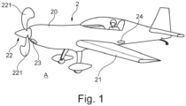
- Figure 1 shows an aircraft 2 in the form of an electrically powered aircraft with a fuselage 20 and wings 21.
- the aircraft 2 includes a drive system with a rotor unit 22, which is driven by an electric machine of the drive system.
- the rotor unit 22 comprises several, here as an example two rotor blades 221.
- the rotor blades 221 are mounted on a hub and thus form a propeller.
- the aircraft 2 includes, for example, a fan instead of a propeller and/or several drive systems, each with at least one propeller, fan or the like.
- the aircraft 2 has an air inlet 23 and (downstream of the aircraft) an air outlet 24.
- the air inlet 23 and the air outlet 24 are each formed on an outer surface of the fuselage 20, but could also be provided at other locations.
- air inlet 23 air can flow from an external environment A of the aircraft 2 (and the electrical machine) to the electrical machine and from there to the air outlet 24. The air can then flow back into the external environment A through the air outlet 24
- FIG. 2 shows parts of the electrical machine 1A of the aircraft 2 in the form of a basic representation.
- the electric machine 1A includes a flow path 10 for cooling fluid F.
- the flow path 10 is bordered by a wall, which is illustrated here with a broken line. This wall is optional, can but contribute to the control of the cooling fluid F.
- the flow path 10 has at least one inlet for the cooling fluid F and at least one outlet.
- the air inlet 23 of the aircraft 2 serves as an inlet of the flow path, the at least one outlet is located downstream at a point further back on the aircraft 2.
- the cooling fluid F is air from the external environment A.
- water can be used or another medium as cooling fluid can be passed through the flow path 10.
- the electrical machine 1A further comprises a housing 11 that is sealed airtight and watertight with respect to the flow path 10.
- the housing 11 can, but does not have to, adjoin the flow path 10.
- the housing 11 has an interior which is sealed airtight and watertight from the flow path.
- the electrical machine 1A further comprises a power supply unit 12.
- the power supply unit 12 is, for example, an inverter that provides a single- or multi-phase, in particular three-phase, alternating voltage.
- the power supply unit 12 is supplied with electrical power, in particular direct current, for example by a battery of the aircraft 2.
- the power supply unit 12 can be arranged outside the housing 11. Alternatively, the power supply unit 12 is arranged within the housing 11.
- the electrical machine 1A includes at least one coil 13A, here two coils 13A, each of which has at least one insulated section 130 and electrical contacts 131.
- the insulated section 130 is provided with an insulation layer 133.
- the contacts 131 of the coils 13A are electrically connected to contacts 120 of the power supply unit 12 within the housing 11. In the area of the contacts 120 of the coils 13A, a conductor of the coils 13A can be uninsulated. The at least one insulated section 130 of the respective coil 13A is arranged in the flow path 10.
- Cooling fluid F flowing through the flow path 10 can flow around and/or through the coils 13A. It can be provided that the cooling fluid F can flow over several, in particular each of a plurality of turns of each of the coils 13A and / or that the cooling fluid F can flow between sections and / or turns of the coils 13A. Due to the direct contact of the cooling fluid F with the coils 13A, particularly good cooling of the coils 13A is possible. Unlike usual, the coils 13A, in particular individual turns, are not protected from direct exposure to cooling fluid in a housing or material surrounding them, for example casting, but are directly exposed to the cooling fluid F.
- the contacts 131 of the coils 13A form the respective ends of the respective coil 13A.
- the contacts 131 of the coils 13A are arranged in the housing 11.
- the end sections of the coils 13A extend through a wall 111 of the housing 11 into the interior of the housing 11.
- the insulation layer 133 completely encloses the respective conductor of the coils 13A outside the housing 11 and extends into the housing 11. All not inside the housing 11 arranged surfaces of the conductor of the respective coil 13A are covered and/or enclosed by the insulation layer 133 (or otherwise).
- the ends of the respective coil 13A are guided through seals 110 on the wall of the housing 11.
- the seals 110 are each in contact with the respective coil 13A and the (or a) wall 111 of the housing 11.
- the housing 11 itself and/or the insulation layer 133 can form the seals 110.
- the seals 110 provide a sufficient watertight and airtight seal of the coils 13A relative to the housing 11, so that no cooling fluid F can get from the flow path 10 into the interior of the housing 11 during operation of the electrical machine 1A.
- the contacts 131 are uninsulated.
- two contacts 131 of the coils 13A are in electrical and physical contact with the contacts 120 of the power supply unit 12.
- Two further contacts 131 of the coils 13A are in electrical connection with one another, in the example shown via a bridge 135.
- the coils 13A are therefore connected in series in this case, but a parallel connection of the coils 13A would also be conceivable, as well as a star or delta connection when using a three-phase machine.
- the coils 13A are formed by a one-piece, continuous conductor. It should be noted that the arrangement with two coils 13A is merely an example and only one coil 13A according to Figure 2 can be provided, as well as a larger number of coils 13A connected in parallel and / or series.
- the power supply unit 12 generally provides a voltage of several hundred volts, in particular a voltage of at least 400 V, in the example shown a voltage of 800 V to the contacts 131 of the coils 13A.
- the voltage is alternating voltage.
- the values mentioned are e.g. B. the effective value or the maximum value of the alternating voltage.
- the housing 11 can have an unfilled interior, but this is not necessarily the case.
- the interior of the housing 11 can be completely filled by the contacts 131, 120 and their leads and optionally other components.
- the housing 11 is produced by casting the contacts 131, 120.
- FIG 3 shows the electrical machine 1A of the aircraft 2 in a schematic sectional view.
- the electric machine 1A is designed in the form of an electric motor (which can additionally or alternatively also be used as a generator).
- the electrical machine 1A is designed as a transverse flux machine.
- the electric machine 1A includes a stator 14A, on which the coils 13A are mounted (in Figure 3 only one of the coils 13A is shown), a rotor 15A and a shaft 16.
- the at least one coil 13A is therefore designed as a stator coil.
- the shaft 16 transmits a torque between the rotor 15A of the electrical machine 1A and the rotor unit 22 of the aircraft 2.
- the rotor unit 22 is attached to the shaft 16 or is otherwise operatively connected to it.
- the drive system includes several electrical machines 1A on the shaft 16.
- the rotor 15A is rotatably mounted about a rotation axis R relative to the stator 14A by means of bearings.
- the stator 14A is fixedly mounted on a carrier of the aircraft 2.
- the stator 14A is fixed relative to the body 20.
- the stator 14A includes a base 140 to which the coil 13A is fixed.
- the coil is 13A thereby attached to the base 140 by means of a holder 141.
- the holder 141 holds the coil 13A.
- the holder 141 holds the coil 13A so that the cooling fluid F can flow around it in the flow path 10.
- the holder 141 makes it possible to dispense with casting the coil 13A.
- the rotor 15A includes a base 150 on which a plurality of (e.g. surface-mounted) magnets 151 in the form of permanent magnets are mounted.
- the magnets 151 are attached to the base 150 of the rotor 15A around the rotation axis R with pairwise alternating polarity. Permanently excited electrical machines allow particularly high power densities and torque densities.
- the base 150 is fixed to the shaft 16.
- the magnets 151 face the coil 13A of the stator 14A.
- the base 150 of the rotor 15A has, for example, two sections which are mirror images of one another and between which the stator 14A is arranged.
- Each of the two sections of the base 151 carries magnets 151 in the present case.
- An electric current through the coil 13A generates a magnetic field which causes the rotor 15A to rotate about the axis of rotation R.
- a gap S is formed between the stator 14A and the sections of the rotor 15A with the magnets 151, through which the magnetic forces act between the stator 14A and the rotor 15A. Magnetic fields bridge the respective gap S.
- the magnetic field lines are guided over the holder 141.
- Each of the two columns S is generally filled with a gas or gas mixture, here with air.
- Each of the two columns S has, at least in sections, the shape of a circular disk.
- the rotor 15A and the stator 14A are separated from each other by a (flat-shaped) air gap on both sides of the stator 14A.
- the stator 14A and the rotor 15A are spaced apart from each other in the axial direction, parallel to the rotation axis R.
- the magnets 151 of the rotor 11 are arranged axially next to the stator 14A.
- the flow path 10 runs through an interior of the stator 14A and radially outward through a passage 142 (in the base 140) of the stator 14A.
- the flow path 10 continues around (optionally through) the coil 13A and further radially outwards through a passage 152 of the rotor 15A towards an air outlet of the flow path 10.
- the coil 13A can be flowed around in several directions.
- the proposed solution therefore ensures that external environmental influences, such as air, dirt and water, are allowed to reach the coil turns.
- the coil 13A can be supplied with rainwater.
- the insulation layer 133 has a thickness in the range of one or several hundred micrometers (e.g. at voltages below 1 kV) and thus allows reliable insulation with particularly good cooling properties. Since the coils 13A do not have to be arranged in a protective housing, the structure of the electric machine 1A can also be simplified. In particular, the housing of the stator of the machine can be partially or completely omitted if the electrical contacting is carried out in the housing of the voltage source.
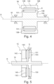
- FIG. 4 shows an electrical machine 1B, which can include the aircraft 2 as an alternative or in addition to the electrical machine 1A.
- the electric machine 1B is designed in the form of an electric motor (which can optionally also be used as a generator) and includes a stator 14B, a rotor 15B and a shaft 16.
- the rotor 15B is rotatably mounted about a rotation axis R relative to the stator 14B by means of a bearing device.
- the electrical machine 1B is designed as an internal rotor, although a design as an external rotor would also be conceivable.
- the stator 14B surrounds the rotor 15B.
- the rotor 15B is at least partially accommodated in the stator 14B.
- the stator 14B can be permanently mounted on a carrier of the aircraft 2.
- the stator 14B can be fixed or fixed relative to the fuselage 20.
- the stator 14B includes a base to which a plurality of coils 13B are fixed.
- the coils 13B are according to Figure 2 isolated and in one in Figure 4 Housing not shown connected.
- the rotor 15B includes a base 150 to which a plurality of magnets 151 in the form of permanent magnets are fixed.
- An electric current through the coils 102 generates a magnetic field which causes the rotor 15B to rotate about the axis of rotation R.
- a gap S is formed between the stator 14B and the rotor 15B, through which the magnetic forces act between the stator 14B and the rotor 15B.
- the gap S is filled with a gas or gas mixture, here with air.
- the gap S has a circular cylindrical shape.
- Figure 5 shows an electrical machine 1C for the aircraft 2, which the aircraft 2 instead of the electrical machine 1A according to Figures 2 and 3 and/or the electrical machine 1B according to Figure 4 , or in addition thereto, may include.
- the electric machine 1C comprises a stator 14C, a rotor 15C which can be rotated relative to the stator 14C, a gap S being formed between the stator 14C and the rotor 15C, via which magnetic forces act between the stator 14C and the rotor 15C.
- the electrical machine 1C is an axial force machine and the magnetic fields bridge the gap S in the axial direction.
- the gap S has the shape of a circular disk.
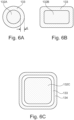
- Figure 6A shows the conductor 132A of one of the coils 13A of the electrical machine 1A Figures 2 and 3 on average. Also the coils 13B, 13C of the electrical machines 1B, 1C according to Figures 4 and 5 may be formed by conductor 132A.
- the conductor 132A has a circular cross section.
- the conductor 132A can be a solid wire or a stranded conductor.
- the conductor 132A is enclosed by the insulation layer 133.
- the insulation layer 133 has a thickness d of 180 ⁇ m corresponding to the voltage of 800 V provided by the power supply unit 12.
- the thickness can be, for example, at least 50 ⁇ m, at least 90 ⁇ m, at least 140 ⁇ m, at least 180 ⁇ m, at least 200 ⁇ m or at least, approximately or exactly 300 ⁇ m.
- the thickness d of the insulation layer 133 is dimensioned such that it provides sufficient electrical insulation for the maximum voltage applied to the contacts 131 of the coil 13A. Compared to conventional coils, where the maximum voltage difference is only between two adjacent ones Coil turns are insulated, this leads to a greater thickness of the insulation layer 133 (for example of 200 micrometers at 1 kV), since insulation is ensured at every point from the directly applied cooling medium.
- the insulation layer 133 has, for example, at least a thickness that provides insulation, in particular is dielectric resistant, at the voltage provided by the power supply unit 12.
- the insulation layer 133 consists of a fluorinated material.
- the material of the insulation layer 133 is, for example, FEP, PTFE, ETFE or PFA.
- the material of the insulation layer 133 comprises or consists of a silicone material. Silicone materials are particularly flexible and do not exhibit cold flow.
- PTFE has a particularly low water absorption. It can be provided that the material of the insulation layer has a water absorption of less than 1%.
- Figure 6B shows an insulated conductor 132B for the electrical machines 1A-1C according to Figures 2-5 .
- the leader can according to Figure 6B be used.
- the conductor 132B is constructed like the conductor 132A Figure 6A , but in contrast has a rectangular cross section.
- Figure 6C shows another insulated conductor 132C for the electrical machines 1A-1C according to Figures 2-5 .
- the conductor 132C is basically constructed like the conductors 132A, 132B Figures 6A and 6B , but in contrast has a square cross section. However, this shape is exemplary and according to conductor 132C Figure 6C could also be made with a round, rectangular or other shaped cross section.
- an outer metal coating 134 is also provided in contrast to the conductors 132A, 132B according to Figures 6A and 6B is according to the conductor 132C Figure 6C Figure 6C Figure 6C Figure 6C Figure 6C an outer metal coating 134 is also provided.
- the outer metal coating 134 encloses the insulation layer 133.
- the metal coating 134 can pass through Plastic metallization, for example specifically applied by electroplating.
- the surface of the insulation layer 133 is roughened by pickling with an oxidative metal salt solution.
- the surface can optionally be coated with metal seeds, e.g. B. palladium, can be activated. Chemical metallization occurs to form an electrically conductive layer.
- a (thin) layer eg 0.3 to 0.4 ⁇ m, for example made of copper or nickel, is created by reducing their metal salts.
- the actual metal layer is then deposited in one or more electroplating baths. Electroplating allows a complete conductive coating on the surface.
- the application of the metal coating 134 can occur before or after winding the coil 13A-13C.
- a coating with nanoparticles is applied.
- Figure 7 further illustrates an optional method for producing the insulation layer 133 of the coils 13A-13C.
- the insulation layer 133 of the respective coils 13A-13C is according to Fig. 2 to 5 made in this way.
- the conductor 132A is first wrapped with a tape B made of the material of the insulation layer 133.
- the tape B is preferably wound in several layers.
- the tape B is wound so that all surface areas of the conductor 132A, which are later arranged in the flow path 10, are covered with the tape B.
- the conductor 132A wrapped with the tape B is then subjected to heat, in the present case in an oven O.
- the material of the tape is sintered and forms the insulation layer 133. If this has not already happened, then the insulated conductor 132A is then bent to form the coil 13A become.
- FIG. 8 shows a method for producing an electrical machine 1A-1C, in particular one of the electrical machines 1A-1C according to Figures 2-5 .
- the procedure includes the following steps: Step S100: Calculate a thickness d of an insulating layer 133 through which an electrical conductor 132A-132C of a coil 13A-13C is to be completely enclosed to form at least one insulated portion 130.
- the thickness d of the insulation layer 133 may be calculated based on a voltage provided by the power supply unit 12 and/or using Paschen's law.
- a voltage can first be specified, e.g. 800 V.
- a rated voltage can be specified, which includes optional safety factors, e.g. 1000 V.
- a density correction for air as a cooling fluid, an air density correction, can be made, which leads to 1250 V, for example.
- a minimum thickness can then be determined, for example, by means of a simulation and/or by calculating Paschen's law. The value obtained in this way (or a value determined in another way for a minimum thickness of the insulation layer), e.g. 90 micrometers, can be multiplied by the relative permittivity of the insulation material (e.g. 2), which results in e.g. 180 micrometers.
- the insulation thickness from turn to turn is 360 micrometers throughout, whereas designs based on common designs that differentiate between turn-to-turn and turn-to-ground insulation typically make do with a tenth of the voltage and therefore insulation thickness.
- Step S101 Providing at least one coil 13A-13C having the at least one insulated portion 130 and contacts 131.
- the at least one coil 13A-13C is provided with an insulation layer 133 with the calculated thickness d.
- Step S102 Electrically connecting and arranging the contacts 131 of the at least one coil 13A-13C such that the contacts 131 of the at least one coil 13A-13C are electrically connected to contacts 120 of the power supply unit 12 within a housing 11 sealed from a flow path 10 for cooling fluid F are connected.
- the housing 11 can be prefabricated or, for example, manufactured at the contacts 131, 120 by casting (for example using a dielectric material).
- Step S103 (which can be carried out before, after or simultaneously with step S102): Arranging the at least one insulated section 130 in the flow path 10.
- parts of the at least one insulated section 130 are fixed by a holder, the holder also being produced by casting can.
- Direct water cooling can also be provided through the insulation layer 133. Water is then passed through the flow path 10 instead of air as the cooling fluid F.
Landscapes
- Engineering & Computer Science (AREA)
- Power Engineering (AREA)
- Aviation & Aerospace Engineering (AREA)
- Manufacturing & Machinery (AREA)
- Microelectronics & Electronic Packaging (AREA)
- Motor Or Generator Cooling System (AREA)
Abstract
Description
- Die vorliegende Offenbarung bezieht sich insbesondere auf eine elektrische Maschine, auf ein Luftfahrzeug und auf ein Verfahren zur Herstellung einer elektrischen Maschine.
- Luftfahrzeuge werden in vielfältigen Ausgestaltungen angetrieben. Verbrennungsmaschinen, z.B. Kolbenmotoren oder Gasturbinentriebwerke, ermöglichen große Reichweiten und hohe Geschwindigkeiten. Antriebe mit einem oder mehreren Elektromotor(en) ermöglichen einen Einsatz von nachhaltig erzeugter Energie und sind mitunter besonders wartungsarm und leise.
- Besonders im Luftfahrtbereich werden mitunter große Antriebsleistungen benötigt, wobei gleichzeitig möglichst kleine Motoren gewünscht sind. Zugleich wird typischerweise ein geringes Gesamtgewicht angestrebt. Die Entwicklung neuerer Elektromotoren für den Luftfahrtbereich erfolgt immer häufiger auf Basis eines Systems mit 800 V, was weitere Herausforderungen für das Design von Elektromotoren mit sich bringt.
- Aufgabe der vorliegenden Erfindung ist es, eine möglichst leistungsfähige elektrische Maschine zu ermöglichen.
- Gemäß einem Aspekt wird eine elektrische Maschine, z.B. für ein Fahrzeug, insbesondere für ein Luftfahrzeug, bereitgestellt. Die elektrische Maschine umfasst einen Strömungspfad für Kühlfluid, ein gegenüber dem Strömungspfad abgedichtetes Gehäuse, eine Stromversorgungseinheit und zumindest eine Spule, die zumindest einen isolierten Abschnitt und Kontakte aufweist, wobei die Kontakte der zumindest einen Spule innerhalb des Gehäuses an Kontakte der Stromversorgungseinheit elektrisch angeschlossen sind und der zumindest eine isolierte Abschnitt im Strömungspfad angeordnet ist.
- Hierdurch wird eine direkte Kühlung der einen oder mehreren Spulen mit Kühlfluid möglich, wobei durch die Isolierung und den elektrischen Anschluss im gegenüber dem Strömungspfad abgedichteten Gehäuse auch ein elektrisch leitfähiges Kühlfluid oder ein Kühlfluid, welches elektrisch leitende Bestandteile enthält, verwendet werden kann. Damit kann die zumindest eine Spule besonders effektiv gekühlt werden, denn das Kühlfluid kann direkt die zumindest eine Spule kühlen und es wird beispielsweise kein zwischengeschalteter Kühlkörper oder dergleichen benötigt. Weiterhin kann eine externe Strömung des Kühlfluids, z.B. Wind, Fahrtwind oder vergleichbare Phänomene in Wasser genutzt werden, wobei das erhitzte Kühlfluid aus der Maschine herausgeleitet werden kann. Dadurch kann auf eine zusätzliche Rückkühlung, wie sie bei zirkulierenden Kühlungen üblich ist, verzichtet werden. Beispielsweise kann der Kühlstrom zusätzlich durch einen Verdichter verstärkt werden. Durch die besonders effektive Kühlung ist eine besonders hohe Leistungsfähigkeit der elektrischen Maschine möglich.
- Die elektrische Maschine kann einen Stator aufweisen. Die zumindest eine Spule kann als Statorspule des Stators ausgebildet sein. Beispielsweise ist die zumindest eine Spule an einer Basis des Stators der elektrischen Maschine befestigt. Dies erlaubt eine besonders leistungsfähige elektrische Maschine.
- Optional ist die zumindest eine Spule mittels einer die zumindest eine Spule im Strömungspfad haltenden Halterung an der Basis des Stators befestigt. So kann die zumindest eine Spule besonders gut mit Kühlfluid beaufschlagt werden.
- Die elektrische Maschine kann ferner einen drehbar zum Stator gelagerten Rotor umfassen. Der Rotor treibt z.B. einen Propeller an, um Schub zu erzeugen.
- Insbesondere kann die elektrische Maschine in Form einer Transversalflussmaschine ausgebildet sein. Dies ermöglicht eine besonders flache Bauweise und große Drehmomente. Die zumindest eine Spule ist z.B. um eine Drehachse des Rotors gewunden. Hierbei ist eine besonders effektive Führung des Kühlfluids um die Spule möglich. Alternativ handelt es sich um eine Radialflussmaschine oder um eine Axialflussmaschine.
- Der Strömungspfad steht optional in Fluidverbindung mit einer Außenumgebung. Bei dem Kühlfluid kann es sich um Luft aus der Außenumgebung handeln. Durch die oben beschriebene Ausgestaltung der elektrischen Maschine kann die zumindest eine Spule direkt mit der Außenluft gekühlt werden, auch wenn diese z.B. Regentropfen enthält. Alternativ kann eine Flüssigkühlung vorgesehen sein, insbesondere mit Wasser als Kühlfluid.
- Der Strömungspfad kann an der Außenumgebung (z.B. an einem Lufteinlass) beginnen und an der Außenumgebung (z.B. an einem Luftauslass) enden. Auf diese Weise ist eine besonders einfache Versorgung mit und Abfuhr von Kühlfluid möglich.
- Der Strömungspfad kann durch die zumindest eine Spule verlaufen. Beispielsweise verläuft der Strömungspfad zwischen und/oder durch Windungen der zumindest einen Spule hindurch. So ist eine besonders gute Kühlung möglich.
- Am isolierten Abschnitt ist ein elektrischer Leiter der Spule vollständig durch eine Isolationsschicht umschlossen. Die Isolationsschicht kann für benachbarte Spulenwindungen separat sein. Die Isolationsschicht kann entlang der Länge des Leiters und um den Leiter herum eine gleichbleibende Dicke aufweisen. Im Gegensatz zu einem Verguss der ganzen Spule ist so eine Durchströmung und damit deutlich bessere Wärmeübertragung an das Kühlfluid möglich. Die Isolationsschicht umschließt insbesondere die gesamte Oberfläche der Spule im Strömungspfad.
- Die Isolationsschicht am isolierten Abschnitt weist z.B. eine minimale Dicke von 50 µm, insbesondere von 90 µm, insbesondere von 140 µm, insbesondere von 180 µm auf. Dies ermöglicht, je nach Größe der angelegten Spannung, eine sichere Isolation, selbst wenn leitfähige Partikel aus der Außenumgebung in den Strömungspfad gelangen. Beispielsweise wird bei einer Spannung von 800 V eine Dicke von vorzugsweise 180 µm verwendet.
- Die Isolationsschicht kann ein fluoriertes Material umfassen oder daraus bestehen. Derartige Materialien erlauben besonders gute dielektrische Eigenschaften und zudem eine besonders gute Widerstandsfähigkeit gegen hohe Temperaturen, Wasser, Chemikalien und Lichtbögen und ermöglichen darüber hinaus auch eine gute mechanische Flexibilität. Bei dem Material der Isolationsschicht handelt es sich z.B. um FEP (Tetrafluorethylen-Hexafluorpropylen-Copolymer), PTFE (Polytetrafluorethylen), ETFE (Ethylen-Tetrafluorethylen-Copolymer) oder PFA (Perfluoralkoxy-Polymer). Alternativ oder zusätzlich kann ein Silikonmaterial verwendet werden.
- Die Isolationsschicht kann mit einer äußeren Schicht, insbesondere Beschichtung versehen sein. Allgemein kann vorgesehen sein, dass die elektrisch isolierende Isolationsschicht durch eine elektrisch leitende Schicht umschlossen ist. Das erlaubt gleichbleibende Bedingungen in Bezug auf elektrische Felder, unabhängig von Wasser oder Schmutz auf der Spule. Um einen vergleichbaren Effekt mit der Isolationsschicht allein zu erzielen, müsste eine wesentlich größere Dicke vorgesehen werden.
- Konkret kann vorgesehen sein, dass eine elektrisch leitfähige äußere Schicht, mit welcher die Isolationsschicht versehen ist, in Form einer Metallbeschichtung ausgebildet ist. Dies ist gut und präzise herstellbar.
- Die Stromversorgungseinheit stellt z.B. eine Spannung von mehreren Hundert Volt, z.B. von 400 V oder mehr, insbesondere von 800 V oder mehr an die Kontakte der zumindest einen Spule bereit. Das erlaubt die Erzeugung eines starken magnetischen Drehfeldes, welches über den Roter einer Propeller antreibt, der es in einen kräftigen Schub umgewandelt.
- Die zumindest eine Spule kann mittels einer Dichtung durch eine Wand des Gehäuses zur Spannungsquelle geführt sein. Die Dichtung dichtet zusammen mit der Isolationsschicht das Gehäuse gegenüber dem Kühlfluid ab, insbesondere wasserdicht und/oder luftdicht.
- Gemäß einem Aspekt wird ein Luftfahrzeug bereitgestellt, umfassend eine Rotoreinheit mit Rotorschaufeln und die elektrische Maschine nach einer beliebigen, hierin beschriebenen Ausgestaltung zum Antrieb der Rotoreinheit. Die Rotoreinheit und die elektrische Maschine bilden ein Antriebssystem für das Luftfahrzeug. Das Antriebssystem dient zur Erzeugung von Schub und/oder Auftrieb für das Luftfahrzeug.
- Gemäß einem Aspekt wird ein Verfahren zur Herstellung einer elektrischen Maschine angegeben, insbesondere der elektrischen Maschine nach einer beliebigen, hierin beschriebenen Ausgestaltung. Das Verfahren umfasst das Bereitstellen zumindest einer Spule, die zumindest einen isolierten Abschnitt und Kontakte aufweist. Das Verfahren umfasst ferner das elektrische Anschließen und Anordnen der Kontakte der zumindest einen Spule derart, dass die Kontakte der zumindest einen Spule innerhalb eines gegenüber einem Strömungspfad für das Kühlfluid abgedichteten Gehäuses an Kontakte der Stromversorgungseinheit elektrisch angeschlossen sind, und das Anordnen des zumindest einen isolierten Abschnitts im Strömungspfad. Hinsichtlich der Vorteile des Verfahrens wird auf die obigen Angaben zur elektrischen Maschine Bezug genommen.
- Das Verfahren kann ferner das Berechnen einer Dicke einer Isolationsschicht, durch welche am isolierten Abschnitt ein elektrischer Leiter der Spule insbesondere vollständig zu umschließen ist, umfassen. Dabei kann die zumindest eine Spule mit einer Isolationsschicht mit der berechneten Dicke bereitgestellt werden, insbesondere entsprechend hergestellt und/oder ausgewählt werden. Das ermöglicht eine maßgeschneiderte Dicke, welche die Spule schützt und dabei ein minimales Gewicht aufweist.
- Die Dicke der Isolationsschicht kann basierend auf einer durch die Stromversorgungseinheit bereitgestellten Spannung und/oder unter Anwendung des Paschen-Gesetzes berechnet werden. Das ermöglicht eine besonders präzise eingestellte Dicke.
- Zum Bereitstellen der zumindest einen Spule kann der elektrische Leiter der Spule mit einem Band aus Isolationsmaterial umwickelt werden, z.B. in mehreren Lagen. Der Leiter mit dem darum gewickelten Band kann sodann, z.B. in einem Ofen, mit Wärme beaufschlagt werden, um die Isolationsschicht zu bilden. Dabei werden übereinander und/oder nebeneinander liegende Lagen des Bandes miteinander verschmolzen. Übereinander und/oder nebeneinander liegende Lagen des Bandes können dabei insbesondere gesintert werden. Es hat sich gezeigt, dass dies eine gegenüber anderen Methoden robustere, da mehrschichtige, Anbringung der Isolationsschicht erlaubt. Alternativ kann durch Extrusion ein Isolationsmaterial auf den Leiter aufgebracht werden, das z.B. eine durchgehende Schicht ausbildet. Eine Fertigung in einem solchen Endlosprozess kann insbesondere bei hohem Materialbedarf kostengünstiger sein. Dabei ist vorzugsweise darauf zu achten, dass das Material keinen sogenannten kalten Fluss aufweist, wie er bei extrudierbaren Fluoropolymeren typischer Weise bekannt ist.
- Es werden nun beispielhaft Ausführungsformen mit Bezug auf die Figuren beschrieben; in den Figuren zeigen in schematischen Darstellungen:
- Figur 1
- ein Luftfahrzeug in Form eines Flugzeugs mit einer elektrisch angetriebenen Rotoreinheit;
- Figur 2
- Komponenten einer elektrischen Maschine des Luftfahrzeugs gemäß
Figur 1 in vereinfachter Darstellung; - Figur 3
- die elektrische Maschine des Luftfahrzeugs gemäß
Figur 1 in Form einer Transversalflussmaschine in einer Querschnittsansicht; - Figur 4
- eine elektrische Maschine für das Luftfahrzeug gemäß
Figur 1 in Form einer Radialflussmaschine; - Figur 5
- eine elektrische Maschine für das Luftfahrzeug gemäß
Figur 1 in Form einer Axialflussmaschine; - Figuren 6A-6C
- Querschnittsansichten möglicher Ausgestaltungen elektrischer Leiter samt Isolationsschicht der elektrischen Maschinen gemäß
Figuren 2 bis 5 ; - Figur 7
- Verfahrensschritte zum Versehen eines elektrischen Leiters für die elektrischen Maschinen gemäß
Figuren 2 bis 5 mit einer Isolationsschicht; und - Figur 8
- ein Verfahren zur Herstellung einer elektrischen Maschine.
-
Figur 1 zeigt ein Luftfahrzeug 2 in Form eines elektrisch angetriebenen Flugzeugs mit einem Rumpf 20 und Flügeln 21. - Das Luftfahrzeug 2 umfasst ein Antriebssystem mit einer Rotoreinheit 22, die durch eine elektrische Maschine des Antriebssystems angetrieben wird. Die Rotoreinheit 22 umfasst mehrere, hier exemplarisch zwei Rotorschaufeln 221. Die Rotorschaufeln 221 sind im gezeigten Beispiel an einer Nabe montiert und bilden damit einen Propeller. In alternativen Ausgestaltungen umfasst das Luftfahrzeug 2 z.B. einen Fan anstelle eines Propellers und/oder mehrere Antriebssysteme mit jeweils zumindest einem Propeller, Fan oder dergleichen.
- Ferner weist das Luftfahrzeug 2 einen Lufteinlass 23 und (dazu stromab am Luftfahrzeug) einen Luftauslass 24 auf. Der Lufteinlass 23 und der Luftauslass 24 sind jeweils an einer äußeren Oberfläche des Rumpfes 20 ausgebildet, könnten aber auch an anderen Stellen vorgesehen sein. Durch den Lufteinlass 23 kann Luft aus einer Außenumgebung A des Luftfahrzeugs 2 (und der elektrischen Maschine) an die elektrische Maschine und von dort zum Luftauslass 24 strömen. Durch den Luftauslass 24 kann die Luft dann zurück in die Außenumgebung A abströmen
-
Figur 2 zeigt Teile der elektrischen Maschine 1A des Luftfahrzeugs 2 in Form einer prinzipiellen Darstellung. Die elektrische Maschine 1A umfasst einen Strömungspfad 10 für Kühlfluid F. Der Strömungspfad 10 wird durch eine Wandung berandet, die hier mit einer unterbrochenen Linie veranschaulicht ist. Diese Wandung ist optional, kann aber zur Lenkung des Kühlfluids F beitragen. Der Strömungspfad 10 weist zumindest einen Einlass für das Kühlfluid F auf und zumindest einen Auslass. Vorliegend dient der Lufteinlass 23 des Luftfahrzeugs 2 als Einlass des Strömungspfades, der zumindest eine Auslass befindet sich stromab an einer weiter hinten gelegenen Stelle des Luftfahrzeugs 2. Bei dem Kühlfluid F handelt es sich vorliegend um Luft aus der Außenumgebung A. Alternativ oder zusätzlich kann Wasser oder ein anderes Medium als Kühlfluid durch den Strömungspfad 10 geleitet werden. - Die elektrische Maschine 1A umfasst ferner ein gegenüber dem Strömungspfad 10 luft- und wasserdicht abgedichtetes Gehäuse 11. Das Gehäuse 11 kann, muss aber nicht an den Strömungspfad 10 angrenzen. Das Gehäuse 11 weist einen Innenraum auf, welcher luft- und wasserdicht gegen den Strömungspfad verschlossen ist.
- Weiter umfasst die elektrische Maschine 1A eine Stromversorgungseinheit 12. Bei der Stromversorgungseinheit 12 handelt es sich z.B. um einen Wechselrichter, der eine ein- oder mehrphasige, insbesondere dreiphasige Wechselspannung bereitstellt. Die Stromversorgungseinheit 12 wird beispielsweise durch eine Batterie des Luftfahrzeugs 2 mit elektrischem Strom, insbesondere Gleichstrom, versorgt. Die Stromversorgungseinheit 12 kann außerhalb des Gehäuses 11 angeordnet sein. Alternativ dazu ist die Stromversorgungseinheit 12 innerhalb des Gehäuses 11 angeordnet.
- Des Weiteren umfasst die elektrische Maschine 1A zumindest eine Spule 13A, hier zwei Spulen 13A, die jeweils zumindest einen isolierten Abschnitt 130 und elektrische Kontakte 131 aufweisen. Der isolierte Abschnitt 130 ist mit einer Isolationsschicht 133 versehen.
- Die Kontakte 131 der Spulen 13A sind innerhalb des Gehäuses 11 an Kontakte 120 der Stromversorgungseinheit 12 elektrisch angeschlossen. Im Bereich der Kontakte 120 der Spulen 13A kann ein Leiter der Spulen 13A unisoliert sein. Der zumindest eine isolierte Abschnitt 130 der jeweiligen Spule 13A ist im Strömungspfad 10 angeordnet.
- Dabei kann durch den Strömungspfad 10 strömendes Kühlfluid F die Spulen 13A umströmen und/oder durchströmen. Dabei kann vorgesehen sein, dass das Kühlfluid F mehrere, insbesondere jede von einer Vielzahl von Windungen jeder der Spulen 13A überströmen kann und/oder dass das Kühlfluid F zwischen Abschnitten und/oder Windungen der Spulen 13A strömen kann. Durch den direkten Kontakt des Kühlfluids F mit den Spulen 13A ist eine besonders gute Kühlung der Spulen 13A möglich. Anders als gewöhnlich sind die Spulen 13A, insbesondere einzelne Windungen, also nicht in einem Gehäuse oder sie umschließendem Material, z.B. Verguss, vor direkter Beaufschlagung mit Kühlfluid geschützt, sondern sind direkt dem Kühlfluid F ausgesetzt.
- Die Kontakte 131 der Spulen 13A bilden die jeweiligen Enden der jeweiligen Spule 13A. Die Kontakte 131 der Spulen 13A sind im Gehäuse 11 angeordnet. Hierzu erstrecken sich die Endabschnitte der Spulen 13Adurch eine Wand 111 des Gehäuses 11 hindurch ins Innere des Gehäuses 11. Die Isolationsschicht 133 umschließt den jeweiligen Leiter der Spulen 13A außerhalb des Gehäuses 11 vollständig und erstreckt sich bis ins Gehäuse 11. Alle nicht im Inneren des Gehäuses 11 angeordneten Oberflächen des Leiters der jeweiligen Spule 13A sind durch die Isolationsschicht 133 (oder anderweitig) überdeckt und/oder eingeschlossen. Dabei sind die Enden der jeweiligen Spule 13A durch Dichtungen 110 an der Wand des Gehäuses 11 geführt. Die Dichtungen 110 stehen jeweils mit der jeweiligen Spule 13A und der (oder einer) Wand 111 des Gehäuses 11 in Berührung. Alternativ können z.B. das Gehäuse 11 selbst und/oder die Isolationsschicht 133 die Dichtungen 110 ausbilden.
- Die Dichtungen 110 stellen eine ausreichende wasser- und luftdichte Abdichtung der Spulen 13A gegenüber dem Gehäuse 11 bereit, sodass im Betrieb der elektrischen Maschine 1A kein Kühlfluid F vom Strömungspfad 10 in das Innere des Gehäuses 11 gelangen kann.
- Im Inneren des Gehäuses 11 sind die Kontakte 131 unisoliert. Vorliegend stehen zwei Kontakte 131 der Spulen 13A in elektrischem und physischem Kontakt mit den Kontakten 120 der Stromversorgungseinheit 12. Zwei weitere der Kontakte 131 der Spulen 13A stehen miteinander, im gezeigten Beispiel über eine Brücke 135, in elektrischer Verbindung. Die Spulen 13A sind somit vorliegend in Reihe geschaltet, denkbar wäre aber auch eine Parallelschaltung der Spulen 13A, weiterhin eine Stern- oder Dreiecksschaltung bei Verwendung einer dreiphasigen Maschine. Ferner könnten die Spulen 13A durch einen einstückig durchgehenden Leiter gebildet werden. Es sei darauf hingewiesen, dass die Anordnung mit zwei Spulen 13A lediglich beispielhaft ist und auch lediglich eine Spule 13A gemäß
Figur 2 vorgesehen sein kann, ebenso wie eine größere Anzahl an parallel und/oder in Reihe geschalteten Spulen 13A. - Die Stromversorgungseinheit 12 stellt im Allgemeinen eine Spannung von mehreren Hundert Volt, insbesondere eine Spannung von mindestens 400 V, im gezeigten Beispiel eine Spannung von 800 V an die Kontakte 131 der Spulen 13A bereit. Bei der Spannung handelt es sich um eine Wechselspannung. Bei den genannten Werten handelt es sich z. B. um den Effektivwert oder den Maximalwert der Wechselspannung.
- Im fertig hergestellten Zustand kann das Gehäuse 11 einen unausgefüllten Innenraum aufweisen, das ist aber nicht zwingend der Fall. Alternativ kann der Innenraum des Gehäuses 11 vollständig durch die Kontakte 131, 120 und deren Zuleitungen und optional weitere Komponenten ausgefüllt sein. Beispielsweise wird das Gehäuse 11 durch Verguss der Kontakte 131, 120 hergestellt.
-
Figur 3 zeigt die elektrische Maschine 1A des Luftfahrzeugs 2 in einer schematischen Schnittdarstellung. Die elektrische Maschine 1A ist in Form eines Elektromotors ausgebildet (der zusätzlich oder alternativ auch als Generator verwendbar sein kann). Konkret ist die elektrische Maschine 1A als Transversalflussmaschine ausgebildet. Die elektrische Maschine 1A umfasst einen Stator 14A, an welchem die Spulen 13A montiert sind (inFigur 3 ist nur eine der Spulen 13A gezeigt), einen Rotor 15A und eine Welle 16. Die zumindest eine Spule 13A ist also als Statorspule ausgebildet. Die Welle 16 überträgt im Betrieb der elektrischen Maschine 1A ein Drehmoment zwischen dem Rotor 15A der elektrischen Maschine 1A und der Rotoreinheit 22 des Luftfahrzeugs 2. Beispielseise ist die Rotoreinheit 22 an der Welle 16 befestigt oder anderweitig damit wirkverbunden. Optional umfasst das Antriebssystem mehrere elektrische Maschinen 1A an der Welle 16. - Der Rotor 15A ist mittels Lager um eine Rotationsachse R relativ zum Stator 14A drehbar gelagert. Der Stator 14A ist fest an einem Träger des Luftfahrzeugs 2 montiert. Beispielsweise ist der Stator 14A relativ zum Rumpf 20 fixiert. Der Stator 14A umfasst eine Basis 140, an welcher die Spule 13A festgelegt ist. Konkret ist die Spule 13A dabei mittels einer Halterung 141 an der Basis 140 befestigt. Die Halterung 141 fasst die Spule 13A ein. Die Halterung 141 hält die Spule 13A durch das Kühlfluid F umströmbar im Strömungspfad 10. Durch die Halterung 141 kann auf einen Verguss der Spule 13A verzichtet werden.
- Der Rotor 15A umfasst eine Basis 150, an der mehrere (z.B. oberflächenmontierte) Magnete 151 in Form von Permanentmagneten montiert sind. Die Magnete 151 sind um die Rotationsachse R herum mit paarweise wechselnder Polarität an der Basis 150 des Rotors 15A befestigt. Permanenterregte elektrische Maschinen erlauben besonders hohe Leistungsdichten und Drehmomentdichten. Die Basis 150 ist an der Welle 16 fixiert. Die Magneten 151 sind der Spule 13A des Stators 14A zugewandt.
- Vorliegend weist die Basis 150 des Rotors 15A beispielhaft zwei Abschnitte auf, welche spiegelbildlich zueinander ausgebildet sind und zwischen denen der Stator 14A angeordnet ist. Jeder der beiden Abschnitte der Basis 151 trägt vorliegend Magnete 151.
- Ein elektrischer Strom durch die Spule 13A erzeugt ein Magnetfeld, welches den Rotor 15A in eine Drehung um die Rotationsachse R versetzt. Zwischen dem Stator 14A und den Abschnitten des Rotors 15A mit den Magneten 151 ist dabei jeweils ein Spalt S ausgebildet, über welchen die magnetischen Kräfte zwischen dem Stator 14A und dem Rotor 15A wirken. Dabei überbrücken magnetische Felder den jeweiligen Spalt S. Vorliegend sind die magnetischen Feldlinien über die Halterung 141 geführt. Jeder der beiden Spalte S ist im Allgemeinen mit einem Gas oder Gasgemisch, hier mit Luft, gefüllt. Jeder der beiden Spalte S weist zumindest abschnittsweise die Form einer Kreisscheibe auf. Somit sind der Rotor 15A und der Stator 14A beiderseits des Stators 14A durch einen (eben geformten) Luftspalt voneinander separiert. Der Stator 14A und der Rotor 15A sind in axialer Richtung, parallel zur Rotationsachse R, voneinander beabstandet. Die Magneten 151 des Rotors 11 sind axial neben dem Stator 14A angeordnet.
- Der Strömungspfad 10 verläuft vorliegend durch einen Innenraum des Stators 14A und radial nach außen durch einen Durchlass 142 (in der Basis 140) des Stators 14A. Weiter verläuft der Strömungspfad 10 um (optional durch) die Spule 13A und weiter radial nach außen durch einen Durchlass 152 des Rotors 15A hin zu einem Luftauslass des Strömungspfades 10. Die Spule 13A kann in mehrere Richtungen umströmt werden.
- Bei der vorgeschlagenen Lösung ist also vorgesehen, dass äußere Umgebungseinflüsse, wie durch Luft, Schmutz und Wasser, bis an die Spulenwindungen gelassen werden. Bei einem (und durch einen) Flug des Luftfahrzeugs 2 ist die Spule 13A mit Regenwasser beaufschlagbar. Die Isolationsschicht 133 weist eine Dicke im Bereich von einem oder mehreren Hundert Mikrometern (z.B. bei Spannungen unter 1 kV) auf und erlaubt so eine sichere Isolation bei gleichzeitig besonders guten Kühleigenschaften. Da die Spulen 13A nicht in einem schützenden Gehäuse angeordnet sein müssen, kann der Aufbau der elektrischen Maschine 1A zudem vereinfacht werden. Insbesondere kann das Gehäuse des Stators der Maschine teilweise oder vollständig entfallen, wenn die elektrische Kontaktierung im Gehäuse der Spannungsquelle durchgeführt wird.
-
Figur 4 zeigt eine elektrische Maschine 1B, welche das Luftfahrzeug 2 alternativ oder zusätzlich zur elektrischen Maschine 1A umfassen kann. Die elektrische Maschine 1B ist in Form eines Elektromotors ausgebildet (der optional auch als Generator verwendbar ist) und umfasst einen Stator 14B, einen Rotor 15B und eine Welle 16. - Der Rotor 15B ist mittels einer Lagereinrichtung um eine Rotationsachse R relativ zum Stator 14B drehbar gelagert. Die elektrische Maschine 1B ist vorliegend als Innenläufer ausgebildet, wobei auch eine Ausbildung als Außenläufer denkbar wäre. Vorliegend umgibt der Stator 14B den Rotor 15B. Der Rotor 15 B ist zumindest abschnittsweise im Stator 14B aufgenommen. Der Stator 14B ist fest an einem Träger des Luftfahrzeugs 2 montierbar. Beispielsweise ist der Stator 14B relativ zum Rumpf 20 fixierbar oder fixiert.
- Der Stator 14B umfasst eine Basis, an welchem mehrere Spulen 13B festgelegt sind. Die Spulen 13B sind gemäß
Figur 2 isoliert und in einem inFigur 4 nicht dargestellten Gehäuse angeschlossen. Der Rotor 15B umfasst eine Basis 150, an dem mehrere Magneten 151 in Form von Permanentmagneten festgelegt sind. - Ein elektrischer Strom durch die Spulen 102 erzeugt ein Magnetfeld, welches den Rotor 15B in eine Drehung um die Rotationsachse R versetzt. Zwischen dem Stator 14B und dem Rotor 15B ist dabei ein Spalt S ausgebildet, über welchen die magnetischen Kräfte zwischen dem Stator 14B und dem Rotor 15B wirken. Der Spalt S ist mit einem Gas oder Gasgemisch, hier mit Luft, gefüllt. Der Spalt S weist eine kreiszylindrische Form auf. Somit sind der Rotor 15B und der Stator 14B durch einen hohlzylindrisch geformten Luftspalt voneinander separiert.
-
Figur 5 zeigt eine elektrische Maschine 1C für das Luftfahrzeug 2, welche das Luftfahrzeug 2 anstelle der elektrischen Maschine 1A gemäßFigur 2 und 3 und/oder der elektrischen Maschine 1B gemäßFigur 4 , oder zusätzlich dazu, umfassen kann. - Die elektrische Maschine 1C umfasst einen Stator 14C, einen relativ zum Stator 14C drehbaren Rotor 15C, wobei zwischen dem Stator 14C und dem Rotor 15C ein Spalt S ausgebildet ist, über welchen magnetische Kräfte zwischen dem Stator 14C und dem Rotor 15C wirken. Bei der elektrischen Maschine 1C handelt es sich um eine Axialkraftmaschine und die magnetischen Felder überbrücken den Spalt S in axialer Richtung. Der Spalt S weist die Form einer Kreisscheibe auf.
-
Figur 6A zeigt den Leiter 132A einer der Spulen 13A der elektrischen Maschine 1A gemäßFiguren 2 und 3 im Schnitt. Auch die Spulen 13B, 13C der elektrischen Maschinen 1B, 1C gemäßFiguren 4 und 5 können durch den Leiter 132A ausgebildet sein. Der Leiter 132A weist einen kreisförmigen Querschnitt auf. Bei dem Leiter 132A kann es sich um einen massiven Draht handeln oder um einen Litzenleiter. Der Leiter 132A ist durch die Isolationsschicht 133 umschlossen. Die Isolationsschicht 133 weist entsprechend der durch die Stromversorgungseinheit 12 bereitgestellten Spannung von 800 V eine Dicke d von 180 µm auf. Je nach der Höhe, der durch die Stromversorgungseinheit 12 bereitgestellten Spannung, kann die Dicke z.B. mindestens 50 µm, mindestens 90 µm, mindestens 140 µm, mindestens 180 µm, mindestens 200 µm oder mindestens, etwa oder genau 300 µm betragen. Die Dicke d der Isolationsschicht 133 wird so bemessen, dass sie eine Isolation für die maximale an den Kontakten 131 der Spule 13A anliegende Spannung eine ausreichende elektrische Isolation bereitstellt. Im Vergleich zu konventionellen Spulen, wo die maximale Spannungsdifferenz lediglich zwischen zwei benachbarten Spulenwindungen isoliert wird, führt dies zu einer größeren Dicke der Isolationsschicht 133 (z.B. von 200 Mikrometern bei 1 kV), da die Isolierung an jeder Stelle zum direkt beaufschlagten Kühlmedium sichergestellt wird. Dadurch kann jedoch auch der Strömungspfad 10 ohne Beschädigung mit Wasser gefüllt werden, insbesondere Wasser mit leitfähigen Eigenschaften. Ein weiterer Vorteil liegt darin, dass bei der Spule 13A für die Isolation nicht zwischen Windung-zu-Masse und Windung-zu-Windung unterschieden wird, was den Aufbau ebenfalls vereinfacht. Die Isolationsschicht 133 weist z.B. zumindest eine Dicke auf, die bei der von der Stromversorgungseinheit 12 bereitgestellten Spannung eine Isolation bereitstellt, insbesondere durchschlagfest ist. - Die Isolationsschicht 133 besteht aus einem fluorierten Material. Bei dem Material der Isolationsschicht 133 handelt es sich z.B. um FEP, PTFE, ETFE oder PFA. Alternativ oder zusätzlich umfasst das Material der Isolationsschicht 133 ein Silikonmaterial oder besteht daraus. Silikonmaterialien sind besonders flexibel und weisen keinen Kalt-Fluss auf. PTFE weist eine besonders geringe Wasseraufnahme auf. Es kann vorgesehen sein, dass das Material der Isolationsschicht eine Wasseraufnahme von unter 1 % aufweist.
-
Figur 6B zeigt einen isolierten Leiter 132B für die elektrischen Maschinen 1A-1C gemäßFiguren 2-5 . Insbesondere für die elektrischen Maschinen 1B, 1C gemäßFiguren 4 und 5 kann der Leiter gemäßFigur 6B verwendet werden. Der Leiter 132B ist aufgebaut wie der Leiter 132A gemäßFigur 6A , weist im Unterschied dazu jedoch einen rechteckigen Querschnitt auf. -
Figur 6C zeigt einen weiteren isolierten Leiter 132C für die elektrischen Maschinen 1A-1C gemäßFiguren 2-5 . Der Leiter 132C ist grundsätzlich aufgebaut wie die Leiter 132A, 132B gemäßFigur 6A und 6B , weist im Unterschied dazu jedoch einen quadratischen Querschnitt auf. Diese Form ist jedoch beispielhaft und der Leiter 132C gemäßFigur 6C könnte auch mit einem runden, rechteckigen oder anders geformten Querschnitt hergestellt werden bzw. sein. Im Unterschied zu den Leitern 132A, 132B gemäßFiguren 6A und 6B ist bei dem Leiter 132C gemäßFigur 6C zusätzlich eine äußere Metallbeschichtung 134 vorgesehen. Die äußere Metallbeschichtung 134 umschließt die Isolationsschicht 133. Die Metallbeschichtung 134 kann durch Kunststoffmetallisierung, z.B. konkret durch Galvanisieren aufgebracht werden. Dies kann z.B. in folgenden Schritten durchgeführt werden:
Optional wird die Oberfläche der Isolationsschicht 133 mittels Beizen mit einer oxidativen Metallsalzlösung aufgeraut. Ferner kann die Oberfläche optional mit Metallkeimen, z. B. Palladium, aktiviert werden. Eine chemische Metallisierung erfolgt zur Bildung einer elektrisch leitenden Schicht. Hierbei wird eine (dünne) Schicht (z.B. 0,3 bis 0,4 µm), beispielsweise aus Kupfer oder Nickel, durch Reduktion aus deren Metallsalzen erzeugt. Daraufhin erfolgt die Abscheidung der eigentlichen Metallschicht in einem oder mehreren Galvanisierbädern. Das Galvanisieren erlaubt eine lückenlose leitende Beschichtung der Oberfläche. Das Aufbringen der Metallbeschichtung 134 kann vor oder nach dem Wickeln der Spule 13A-13C erfolgen. Optional wird eine Beschichtung mit Nanopartikeln aufgebracht. -
Figur 7 veranschaulicht ferner ein optionales Verfahren zur Herstellung der Isolationsschicht 133 der Spulen 13A-13C. Vorliegend ist die Isolationsschicht 133 der jeweiligen Spulen 13A-13C gemäßFig. 2 bis 5 in dieser Weise hergestellt. Hierbei wird zunächst der Leiter 132A mit einem Band B aus dem Material der Isolationsschicht 133 umwickelt. Das Band B wird dabei vorzugsweise in mehreren Lagen gewickelt. Das Band B wird so gewickelt, dass es sämtliche Oberflächenbereiche des Leiters 132A, welche später im Strömungspfad 10 angeordnet sind, mit dem Band B überdeckt sind. - Daraufhin wird der mit dem Band B umwickelte Leiter 132A mit Wärme beaufschlagt, vorliegend in einem Ofen O. Hierbei wird das Material des Bandes gesintert und bildet die Isolationsschicht 133. Falls nicht bereits geschehen, dann daraufhin der isolierte Leiter 132A zur Bildung der Spule 13A gebogen werden.
- Dieses Wicklungsverfahren weist nicht den Nachteil anderer Methoden, z.B. einer kostengünstigeren Extrusion, des sogenannten kalten Flusses auf, welcher zu irreversiblen Deformationen der Isolationsschicht führen kann und daher die Lebenszeit der entsprechenden Spule verringern kann, wenn über längere Zeit ein (mitunter sehr geringer) mechanischer Druck auf die Isolationsschicht ausgeübt wird.
Figur 8 zeigt ein Verfahren zur Herstellung einer elektrischen Maschine 1A-1C, insbesondere einer der elektrischen Maschinen 1A-1C gemäßFiguren 2-5 . Das Verfahren umfasst die folgenden Schritte:
Schritt S100: Berechnen einer Dicke d einer Isolationsschicht 133, durch welche ein elektrischer Leiter 132A-132C einer Spule 13A-13C zur Bildung zumindest eines isolierten Abschnitts 130 vollständig zu umschließen ist. Die Dicke d der Isolationsschicht 133 kann basierend auf einer durch die Stromversorgungseinheit 12 bereitgestellten Spannung und/oder unter Anwendung des Paschen-Gesetzes berechnet werden. - Konkret kann hierbei zunächst eine Spannung vorgegeben werden, z.B. 800 V. Es kann eine Bemessungsspannung festgelegt werden, welche optionale Sicherheitsfaktoren einschließt, z.B. 1000 V. Eine Dichtekorrektur, bei Luft als Kühlfluid eine Luftdichtekorrektur, kann vorgenommen werden, was z.B. zu 1250 V führt. Dann kann z.B. mittels einer Simulation und/oder mit Berechnung des Paschen-Gesetzes eine minimale Dicke ermittelt werden. Der so erhaltene Wert (oder ein anders ermittelter Wert für eine minimale Dicke der Isolationsschicht), z.B. 90 Mikrometer, kann mit der relativen Permittivität des Isolationsmaterials multipliziert werden (z.B. 2), woraus z.B. 180 Mikrometer folgen. In diesem Beispiel beträgt die Isolationsdicke von Windung zu Windung dann durchgehend 360 Mikrometer, wohingegen Entwürfe nach gängiger Machart, die zwischen Windung-Windung- und Windung-Masse-Isolierung unterschieden, typischerweise bereits mit einem Zehntel der Spannung und folglich Isolationsdicke auskommen.
- Schritt S101: Bereitstellen zumindest einer Spule 13A-13C, die den zumindest einen isolierten Abschnitt 130 und Kontakte 131 aufweist. Dabei wird die zumindest eine Spule 13A-13C mit einer Isolationsschicht 133 mit der berechneten Dicke d bereitgestellt.
- Schritt S102: Elektrisches Anschließen und Anordnen der Kontakte 131 der zumindest einen Spule 13A-13C derart, dass die Kontakte 131 der zumindest einen Spule 13A-13C innerhalb eines gegenüber einem Strömungspfad 10 für Kühlfluid F abgedichteten Gehäuses 11 an Kontakte 120 der Stromversorgungseinheit 12 elektrisch angeschlossen sind. Das Gehäuse 11 kann vorgefertigt sein oder, z.B. durch Verguss (z.B. durch ein dielektrisches Material), an den Kontakten 131, 120 hergestellt werden.
- Schritt S103 (der vor, nach oder gleichzeitig mit Schritt S102 durchgeführt werden kann): Anordnen des zumindest einen isolierten Abschnitts 130 im Strömungspfad 10. Optional werden Teile des zumindest einen isolierten Abschnitts 130 durch eine Halterung fixiert, wobei die Halterung auch durch Verguss hergestellt werden kann.
- Durch die Isolationsschicht 133 kann auch eine direkte Wasserkühlung vorgesehen werden. Dann wird als Kühlfluid F anstatt Luft Wasser durch den Strömungspfad 10 geleitet.
-
- 1A-1C
- elektrische Maschine
- 10
- Strömungspfad
- 11
- Gehäuse
- 110
- Dichtung
- 111
- Wand
- 12
- Stromversorgungseinheit
- 120
- Kontakt
- 13A-13C
- Spule
- 130
- isolierter Abschnitt
- 131
- Kontakt
- 132A-132C
- Leiter
- 133
- Isolationsschicht
- 134
- Metallbeschichtung
- 135
- Brücke
- 14A-14C
- Stator
- 140
- Basis
- 141
- Halterung
- 142
- Durchlass
- 15A-15C
- Rotor
- 150
- Basis
- 151
- Magnet
- 152
- Durchlass
- 16
- Welle
- 2
- Luftfahrzeug
- 20
- Rumpf
- 21
- Flügel
- 22
- Rotoreinheit
- 221
- Rotorschaufel
- 23
- Lufteinlass
- 24
- Luftauslass
- A
- Außenumgebung
- B
- Band
- d
- Dicke
- F
- Kühlfluid
- O
- Ofen
- R
- Rotationsachse
- S
- Spalt
Claims (15)
- Elektrische Maschine (1A-1C), umfassend:- einen Strömungspfad (10) für Kühlfluid (F),- ein gegenüber dem Strömungspfad (10) abgedichtetes Gehäuse (11),- eine Stromversorgungseinheit (12) und- zumindest eine Spule (13A-13C), die zumindest einen isolierten Abschnitt (130) und Kontakte (131) aufweist,wobei die Kontakte (131) der zumindest einen Spule (13A-13C) innerhalb des Gehäuses (11) an Kontakte (120) der Stromversorgungseinheit (12) elektrisch angeschlossen sind und der zumindest eine isolierte Abschnitt (130) im Strömungspfad (10) angeordnet ist.
- Elektrische Maschine (1A-1C) nach Anspruch 1, wobei die zumindest eine Spule (13A-13C) als Statorspule ausgebildet ist und an einer Basis (140) eines Stators (14A-14C) der elektrischen Maschine (1A-1C) befestigt ist.
- Elektrische Maschine (1A-1C) nach Anspruch 2, wobei die zumindest eine Spule (13A-13C) mittels einer die zumindest eine Spule (13A-13C) im Strömungspfad haltenden Halterung (141) an der Basis (140) des Stators (14A-14C) befestigt ist.
- Elektrische Maschine (1A-1C) nach einem der vorhergehenden Ansprüche, ausgebildet in Form einer Transversalflussmaschine.
- Elektrische Maschine (1A-1C) nach einem der vorhergehenden Ansprüche, wobei der Strömungspfad (10) in Fluidverbindung mit einer Außenumgebung (A) steht und wobei das Kühlfluid (F) Luft aus der Außenumgebung (A) ist.
- Elektrische Maschine (1A-1C) nach Anspruch 5, wobei der Strömungspfad (10) an der Außenumgebung (A) beginnt und an der Außenumgebung (A) endet.
- Elektrische Maschine (1A-1C) nach einem der vorhergehenden Ansprüche, wobei der Strömungspfad (10) durch Windungen der zumindest einen Spule (13A-13C) verläuft.
- Elektrische Maschine (1A-1C) nach einem der vorhergehenden Ansprüche, wobei am isolierten Abschnitt (130) ein elektrischer Leiter (132A-132C) der Spule (13A-13C) vollständig durch eine Isolationsschicht (133) umschlossen ist.
- Elektrische Maschine (1A-1C) nach Anspruch 8, wobei die Isolationsschicht (133) ein fluoriertes Material umfasst oder daraus besteht, insbesondere ein Silikonmaterial.
- Elektrische Maschine (1A-1C) nach Anspruch 8 oder 9, wobei die Isolationsschicht (133) mit einer elektrisch leitfähigen äußeren Schicht versehen ist.
- Elektrische Maschine (1A-1C) nach Anspruch 10, wobei die elektrisch leitfähige äußere Schicht in Form einer Metallbeschichtung (134) ausgebildet ist.
- Luftfahrzeug (2) mit einer Rotorschaufeln (221) umfassenden Rotoreinheit (22) und der elektrischen Maschine (1A-1C) nach einem der vorhergehenden Ansprüche zum Antrieb der Rotoreinheit (22).
- Verfahren zur Herstellung einer elektrischen Maschine (1A-1C), insbesondere nach einem der Ansprüche 1 bis 11, umfassend:- Bereitstellen (S101) zumindest einer Spule (13A-13C), die zumindest einen isolierten Abschnitt (130) und Kontakte (131) aufweist, und- elektrisches Anschließen und Anordnen (S102) der Kontakte (131) der zumindest einen Spule (13A-13C) derart, dass die Kontakte (131) der zumindest einen Spule (13A-13C) innerhalb eines gegenüber einem Strömungspfad (10) für Kühlfluid (F) abgedichteten Gehäuses (11) an Kontakte (120) der Stromversorgungseinheit (12) elektrisch angeschlossen sind, und Anordnen (S103) des zumindest einen isolierten Abschnitts (130) im Strömungspfad (10).
- Verfahren nach Anspruch 13, ferner umfassend:- Berechnen (S100) einer Dicke (d) einer Isolationsschicht (133), durch welche am isolierten Abschnitt (130) ein elektrischer Leiter (132A-132C) der Spule (13A-13C) vollständig zu umschließen ist,wobei die zumindest eine Spule (13A-13C) mit einer Isolationsschicht (133) mit der berechneten Dicke (d) bereitgestellt wird.
- Verfahren nach Anspruch 14, wobei zum Bereitstellen der zumindest einen Spule (13A-13C) der elektrische Leiter (132A-132C) der Spule (13A-13C) mit einem Band (B) aus Isolationsmaterial umwickelt wird, welches sodann mit Wärme beaufschlagt wird, um die Isolationsschicht (133) zu bilden.
Applications Claiming Priority (1)
| Application Number | Priority Date | Filing Date | Title |
|---|---|---|---|
| DE102022209762.9A DE102022209762A1 (de) | 2022-09-16 | 2022-09-16 | Elektrische Maschine mit offener Spulenwicklung zur Direktkühlung |
Publications (1)
| Publication Number | Publication Date |
|---|---|
| EP4340185A1 true EP4340185A1 (de) | 2024-03-20 |
Family
ID=88021125
Family Applications (1)
| Application Number | Title | Priority Date | Filing Date |
|---|---|---|---|
| EP23197214.2A Pending EP4340185A1 (de) | 2022-09-16 | 2023-09-13 | Elektrische maschine mit offener spulenwicklung zur direktkühlung |
Country Status (3)
| Country | Link |
|---|---|
| US (1) | US12445014B2 (de) |
| EP (1) | EP4340185A1 (de) |
| DE (1) | DE102022209762A1 (de) |
Citations (5)
| Publication number | Priority date | Publication date | Assignee | Title |
|---|---|---|---|---|
| JPH08191559A (ja) * | 1995-01-10 | 1996-07-23 | Shinko Electric Co Ltd | 回転電機用の耐アンモニア絶縁の固定子コイルの製造方法 |
| DE112007000364T5 (de) * | 2006-02-24 | 2008-11-27 | Mitsubishi Cable Industries, Ltd. | Leiteranordnung und Verfahren zur Herstellung derselben |
| EP2568580A2 (de) * | 2011-09-12 | 2013-03-13 | Kabushiki Kaisha Toyota Jidoshokki | Elektrischer Verdichter |
| KR20210007481A (ko) * | 2019-07-11 | 2021-01-20 | 엘지전자 주식회사 | 모터의 고정자 및 이를 구비한 전동식 압축기 |
| US20220228599A1 (en) * | 2019-10-01 | 2022-07-21 | Hanon Systems | Sealing and insulating arrangement for a device used for driving a compressor and device for driving a compressor |
Family Cites Families (7)
| Publication number | Priority date | Publication date | Assignee | Title |
|---|---|---|---|---|
| DE3536538A1 (de) * | 1985-10-12 | 1987-04-23 | Weh Herbert | Transversalfluss-maschine mit permanenterregung |
| US7390757B2 (en) * | 2005-11-15 | 2008-06-24 | Applied Materials, Inc. | Methods for improving low k FSG film gap-fill characteristics |
| JP2012507251A (ja) * | 2008-09-23 | 2012-03-22 | エアロヴァイロンメント インコーポレイテッド | 圧縮型モータ巻線 |
| DE102009060959A1 (de) * | 2009-12-30 | 2011-07-07 | Robert Bosch GmbH, 70469 | Transversalflussmaschine |
| US10651702B2 (en) * | 2014-09-04 | 2020-05-12 | Coreless Motor Co., Ltd. | Coreless rotating electrical machine with stator including cylindrical coil and cooling method therefor |
| DE102019116264A1 (de) * | 2019-06-14 | 2020-12-17 | Gkn Automotive Limited | Elektromotorische antriebsradanordnung für ein kraftfahrzeug |
| US11791693B2 (en) * | 2020-08-31 | 2023-10-17 | Ge Aviation Systems, Llc | Electric machine having an electrically insulative manifold |
-
2022
- 2022-09-16 DE DE102022209762.9A patent/DE102022209762A1/de active Pending
-
2023
- 2023-09-13 EP EP23197214.2A patent/EP4340185A1/de active Pending
- 2023-09-16 US US18/369,147 patent/US12445014B2/en active Active
Patent Citations (5)
| Publication number | Priority date | Publication date | Assignee | Title |
|---|---|---|---|---|
| JPH08191559A (ja) * | 1995-01-10 | 1996-07-23 | Shinko Electric Co Ltd | 回転電機用の耐アンモニア絶縁の固定子コイルの製造方法 |
| DE112007000364T5 (de) * | 2006-02-24 | 2008-11-27 | Mitsubishi Cable Industries, Ltd. | Leiteranordnung und Verfahren zur Herstellung derselben |
| EP2568580A2 (de) * | 2011-09-12 | 2013-03-13 | Kabushiki Kaisha Toyota Jidoshokki | Elektrischer Verdichter |
| KR20210007481A (ko) * | 2019-07-11 | 2021-01-20 | 엘지전자 주식회사 | 모터의 고정자 및 이를 구비한 전동식 압축기 |
| US20220228599A1 (en) * | 2019-10-01 | 2022-07-21 | Hanon Systems | Sealing and insulating arrangement for a device used for driving a compressor and device for driving a compressor |
Also Published As
| Publication number | Publication date |
|---|---|
| US12445014B2 (en) | 2025-10-14 |
| DE102022209762A1 (de) | 2024-03-21 |
| US20240097530A1 (en) | 2024-03-21 |
Similar Documents
| Publication | Publication Date | Title |
|---|---|---|
| DE60110009T2 (de) | Wechselstromgenerator für Fahrzeuge | |
| DE69804284T3 (de) | Fahrzeugsgenerator | |
| DE69830869T2 (de) | Wechselstromgenerator für Kraftfahrzeuge | |
| DE60116944T2 (de) | Statoranordnung einer rotierenden elektrischen Maschine | |
| DE69304517T2 (de) | Elektrische stromerzeuger | |
| DE60001526T2 (de) | Elektrische rotierende Maschine mit einer Mehrzahl von Leiterabschnitten und Verfahren zur Herstellung desselben | |
| DE112012002259B4 (de) | Rotierende elektrische Maschine und Verfahren für ihre Herstellung | |
| EP4214821B1 (de) | Dynamoelektrische rotatorische maschine mit einem spaltrohr | |
| DE102013204047B4 (de) | Elektrische Einrichtung mit einer Spule | |
| DE3916253A1 (de) | Oelgefuellter, elektrischer tauchpumpen-motor mit unlackiertem stator-aufbau | |
| DE102010035039A1 (de) | Pumpe mit einem Elektromotor sowie Verfahren zum Einschalten einer derartigen Pumpe | |
| DE102017010383A1 (de) | Rotationsmotor mit einem Rotorelement und mit einem Statorelement | |
| DE69826534T2 (de) | Wechselstromgenerator für Fahrzeuge | |
| DE102022209762A1 (de) | Elektrische Maschine mit offener Spulenwicklung zur Direktkühlung | |
| DE10008807A1 (de) | Elektrische Rotationsmaschine und Verfahren zum Kühlen einer elektrischen Rotationsmaschine | |
| DE102013114908A1 (de) | Drehende elektrische Maschine | |
| DE102013009677B4 (de) | Antriebseinheit für ein Luftfahrzeug | |
| DE102011116398A1 (de) | Anlasser | |
| DE102009000707A1 (de) | Gleichstrommotor | |
| DE60211661T2 (de) | Luftlaufrad und gehäuse für ein solches laufrad | |
| DE102024120458A1 (de) | Temperaturüberwachte Spule einer elektrischen Maschine | |
| DE69205337T2 (de) | Verbesserungen an elektrischen Drehmaschinen. | |
| DE102011102877B3 (de) | Triebwerkssimulator für Windkanalmodelle, Verfahren zum Herstellen einer Heizbeschichtung an einem Strömungskörper und Verwendung einer Beschichtung mit einem Leitfähigkeitsadditiv an einem Strömungskörper | |
| LU502604B1 (de) | Stator für einen elektrischen Luftfahrtantrieb und elektrischer Luftfahrtantrieb | |
| WO2007107133A1 (de) | Elektromotor |
Legal Events
| Date | Code | Title | Description |
|---|---|---|---|
| PUAI | Public reference made under article 153(3) epc to a published international application that has entered the european phase |
Free format text: ORIGINAL CODE: 0009012 |
|
| STAA | Information on the status of an ep patent application or granted ep patent |
Free format text: STATUS: THE APPLICATION HAS BEEN PUBLISHED |
|
| AK | Designated contracting states |
Kind code of ref document: A1 Designated state(s): AL AT BE BG CH CY CZ DE DK EE ES FI FR GB GR HR HU IE IS IT LI LT LU LV MC ME MK MT NL NO PL PT RO RS SE SI SK SM TR |
|
| STAA | Information on the status of an ep patent application or granted ep patent |
Free format text: STATUS: REQUEST FOR EXAMINATION WAS MADE |
|
| 17P | Request for examination filed |
Effective date: 20240610 |
|
| RBV | Designated contracting states (corrected) |
Designated state(s): AL AT BE BG CH CY CZ DE DK EE ES FI FR GB GR HR HU IE IS IT LI LT LU LV MC ME MK MT NL NO PL PT RO RS SE SI SK SM TR |