EP4339924A1 - Appareil d'affichage et son procédé de commande - Google Patents
Appareil d'affichage et son procédé de commande Download PDFInfo
- Publication number
- EP4339924A1 EP4339924A1 EP21961837.8A EP21961837A EP4339924A1 EP 4339924 A1 EP4339924 A1 EP 4339924A1 EP 21961837 A EP21961837 A EP 21961837A EP 4339924 A1 EP4339924 A1 EP 4339924A1
- Authority
- EP
- European Patent Office
- Prior art keywords
- seat
- adjustment
- component
- horn
- page
- Prior art date
- Legal status (The legal status is an assumption and is not a legal conclusion. Google has not performed a legal analysis and makes no representation as to the accuracy of the status listed.)
- Pending
Links
- 238000000034 method Methods 0.000 title claims abstract description 72
- 230000004044 response Effects 0.000 claims abstract description 258
- 230000000007 visual effect Effects 0.000 claims description 18
- 230000001960 triggered effect Effects 0.000 claims description 16
- 230000008859 change Effects 0.000 claims description 6
- 230000000875 corresponding effect Effects 0.000 description 19
- 230000001276 controlling effect Effects 0.000 description 18
- 238000010586 diagram Methods 0.000 description 14
- 230000008569 process Effects 0.000 description 13
- 238000004891 communication Methods 0.000 description 10
- 238000003825 pressing Methods 0.000 description 6
- 238000005516 engineering process Methods 0.000 description 5
- 230000005236 sound signal Effects 0.000 description 4
- 238000004590 computer program Methods 0.000 description 3
- 230000003287 optical effect Effects 0.000 description 3
- 230000001133 acceleration Effects 0.000 description 2
- 230000002596 correlated effect Effects 0.000 description 2
- 238000009792 diffusion process Methods 0.000 description 2
- 230000006870 function Effects 0.000 description 2
- 230000003993 interaction Effects 0.000 description 2
- 238000007726 management method Methods 0.000 description 2
- 230000004048 modification Effects 0.000 description 2
- 238000012986 modification Methods 0.000 description 2
- 230000006978 adaptation Effects 0.000 description 1
- 230000004075 alteration Effects 0.000 description 1
- 230000009286 beneficial effect Effects 0.000 description 1
- 238000013500 data storage Methods 0.000 description 1
- 238000003384 imaging method Methods 0.000 description 1
- 239000004973 liquid crystal related substance Substances 0.000 description 1
- 230000002093 peripheral effect Effects 0.000 description 1
- 230000003068 static effect Effects 0.000 description 1
Images


Classifications
-
- B—PERFORMING OPERATIONS; TRANSPORTING
- B60—VEHICLES IN GENERAL
- B60K—ARRANGEMENT OR MOUNTING OF PROPULSION UNITS OR OF TRANSMISSIONS IN VEHICLES; ARRANGEMENT OR MOUNTING OF PLURAL DIVERSE PRIME-MOVERS IN VEHICLES; AUXILIARY DRIVES FOR VEHICLES; INSTRUMENTATION OR DASHBOARDS FOR VEHICLES; ARRANGEMENTS IN CONNECTION WITH COOLING, AIR INTAKE, GAS EXHAUST OR FUEL SUPPLY OF PROPULSION UNITS IN VEHICLES
- B60K35/00—Instruments specially adapted for vehicles; Arrangement of instruments in or on vehicles
- B60K35/10—Input arrangements, i.e. from user to vehicle, associated with vehicle functions or specially adapted therefor
-
- B—PERFORMING OPERATIONS; TRANSPORTING
- B60—VEHICLES IN GENERAL
- B60K—ARRANGEMENT OR MOUNTING OF PROPULSION UNITS OR OF TRANSMISSIONS IN VEHICLES; ARRANGEMENT OR MOUNTING OF PLURAL DIVERSE PRIME-MOVERS IN VEHICLES; AUXILIARY DRIVES FOR VEHICLES; INSTRUMENTATION OR DASHBOARDS FOR VEHICLES; ARRANGEMENTS IN CONNECTION WITH COOLING, AIR INTAKE, GAS EXHAUST OR FUEL SUPPLY OF PROPULSION UNITS IN VEHICLES
- B60K35/00—Instruments specially adapted for vehicles; Arrangement of instruments in or on vehicles
- B60K35/20—Output arrangements, i.e. from vehicle to user, associated with vehicle functions or specially adapted therefor
- B60K35/25—Output arrangements, i.e. from vehicle to user, associated with vehicle functions or specially adapted therefor using haptic output
-
- B—PERFORMING OPERATIONS; TRANSPORTING
- B60—VEHICLES IN GENERAL
- B60K—ARRANGEMENT OR MOUNTING OF PROPULSION UNITS OR OF TRANSMISSIONS IN VEHICLES; ARRANGEMENT OR MOUNTING OF PLURAL DIVERSE PRIME-MOVERS IN VEHICLES; AUXILIARY DRIVES FOR VEHICLES; INSTRUMENTATION OR DASHBOARDS FOR VEHICLES; ARRANGEMENTS IN CONNECTION WITH COOLING, AIR INTAKE, GAS EXHAUST OR FUEL SUPPLY OF PROPULSION UNITS IN VEHICLES
- B60K2360/00—Indexing scheme associated with groups B60K35/00 or B60K37/00 relating to details of instruments or dashboards
- B60K2360/143—Touch sensitive instrument input devices
- B60K2360/1438—Touch screens
- B60K2360/1442—Emulation of input devices
-
- B—PERFORMING OPERATIONS; TRANSPORTING
- B62—LAND VEHICLES FOR TRAVELLING OTHERWISE THAN ON RAILS
- B62D—MOTOR VEHICLES; TRAILERS
- B62D1/00—Steering controls, i.e. means for initiating a change of direction of the vehicle
- B62D1/02—Steering controls, i.e. means for initiating a change of direction of the vehicle vehicle-mounted
- B62D1/04—Hand wheels
- B62D1/046—Adaptations on rotatable parts of the steering wheel for accommodation of switches
-
- B—PERFORMING OPERATIONS; TRANSPORTING
- B62—LAND VEHICLES FOR TRAVELLING OTHERWISE THAN ON RAILS
- B62D—MOTOR VEHICLES; TRAILERS
- B62D1/00—Steering controls, i.e. means for initiating a change of direction of the vehicle
- B62D1/02—Steering controls, i.e. means for initiating a change of direction of the vehicle vehicle-mounted
- B62D1/04—Hand wheels
- B62D1/10—Hubs; Connecting hubs to steering columns, e.g. adjustable
Definitions
- the present disclosure relates to the display field, and in particular to display devices, methods for controlling the same and computer readable storage media.
- a horn button in a vehicle is a physical button disposed in the center of a steering wheel.
- a user there is almost no other response except for controlling the horn to honk.
- embodiments of the present disclosure provide a display device, a method of controlling the display device and a computer readable storage medium, so as to solve the technical problems in the prior arts.
- a display device which can be applied to a steering wheel.
- the display device includes a display component, a touch component, a response component and a controller.
- the display component is configured to display a horn page.
- the touch component is configured to generate a horn touch signal according to a first touching operation occurring on the horn page, and output the horn touch signal to the controller and the response component.
- the controller is configured to trigger a horn to honk according to the horn touch signal.
- the response component is configured to generate a first tactile response according to the horn touch signal while the horn is honking.
- the controller is further configured to determine, according to the horn touch signal generated by the touch component, touch intensity of the first touching operation; and in response to determining that the touch intensity is greater than or equal to a touch intensity threshold, trigger the horn to honk.
- the display device includes a touch effective region and the controller is further configured to determine, according to the horn touch signal, a position of the first touching operation; and in response to determining that the position of the first touching operation is within the touch effective region, trigger the horn to honk.
- the response component is further configured to generate visual feedback while the horn is honking.
- the controller is further configured to: in a duration of the first touching operation, control the horn to honk; and/or, at an end of the first touching operation, control the horn to stop honking.
- the touch component is further configured to generate, according to a received first switching operation, a first switching touch signal and send the first switching touch signal to the controller, where the first switching operation includes a touching operation for a seat adjustment identifier in a navigation bar displayed in the display component;
- the controller is further configured to control, according to the first switching touch signal, the display component to switch from displaying the horn page to displaying a seat adjustment page;
- the touch component is further configured to generate, according to a second touching operation for the seat adjustment page, an adjustment touch signal and send the adjustment touch signal to the controller and the response component;
- the controller is further configured to adjust a position of a seat according to the adjustment touch signal;
- the response component is further configured to generate, according to the adjustment touch signal, a second tactile response while the position of the seat is being adjusted.
- the seat adjustment page displays a seat position of the seat; the touch component is further configured to send the adjustment touch signal to the display component; and the display component is configured to change, according to the adjustment touch signal, the displayed seat position.
- the seat adjustment page is provided with at least one horizontal position adjustment bar; the touch component is configured to generate, according to the second touching operation for the horizontal position adjustment bar, a first adjustment touch signal, and transmit the first adjustment touch signal to the controller and the response component; the controller is configured to adjust, according to the first adjustment touch signal, a horizontal position of the seat; and the response component is configured to generate, according to the first adjustment touch signal, a tactile response of sliding friction while the horizontal position of the seat is being adjusted.
- the seat adjustment page is provided with at least one seat backrest angle adjustment bar;
- the touch component is configured to generate, according to the second touching operation for the seat backrest angle adjustment bar, a second adjustment touch signal, and transmit the second adjustment touch signal to the controller and the response component;
- the controller is configured to adjust, according to the second adjustment touch signal, a seat backrest pitch angle;
- the response component is configured to generate, according to the second adjustment touch signal, a tactile response of rotating friction while the seat backrest pitch angle is being adjusted.
- the seat adjustment page is provided with a plurality of adjustment regions; the touch component is further configured to determine a target region where the second touching operation is located from the plurality of adjustment regions, and indicate to the controller that the second touching operation is located in the target region; and the controller is configured to determine an adjustment speed proportion corresponding to the target region, determine an adjustment speed according to the adjustment speed proportion and the adjustment touch signal, and adjust the position of the seat according to the adjustment speed.
- the touch component is further configured to record a length of time during which no operation for the seat adjustment page is received, and in response to determining that the recorded length of time is greater than a first predetermined time length, send a first expiration signal to the controller; and the controller is further configured to control, according to the first expiration signal, the display component to switch from displaying the seat adjustment page to displaying the horn page.
- the touch component is further configured to generate, according to a received second switching operation, a second switching touch signal, and send the second switching touch signal to the controller, where the second switching operation includes a touching operation for a voice call identifier in a navigation bar displayed by the display component;
- the controller is further configured to control, according to the second switching touch signal, the display component to switch from displaying the horn page to displaying a voice call page;
- the touch component is further configured to generate, according to a received third touching operation for the voice call page, a call touch signal, and send the call touch signal to the controller and the response component;
- the controller is further configured to trigger a voice call according to the call touch signal; and the response component is further configured to generate, according to the call touch signal, a third tactile response while the voice call is being triggered.
- the voice call page displays at least a selection region and a call region
- the third touching operation includes a selection touching operation for the selection region and a call touching operation for the call region
- the touch component is further configured to generate a selection touch signal according to the received selection touching operation, and send the selection touch signal to the display component and the response component
- the display component is further configured to select a target contact according to the selection touch signal
- the response component is further configured to generate a tactile response while the display component is performing the target contact selection
- the touch component is further configured to generate a call touch signal according to the received call touching operation, and send the call touch signal to the control component and the response component
- the control component is further configured to call the target contact according to the call touch signal
- the response component is further configured to generate a tactile response according to the call touch signal while the target contact is being called.
- the call region includes a central region and an edge region;
- the touch component is configured to generate a first call touch signal according to a call touching operation for the central region, generate a second call touch signal according to a call touching operation for the edge region, and send the first call touch signal and the second call touch signal to the response component;
- the response component is further configured to generate, according to the first call touch signal and the second call touch signal, different tactile responses respectively.
- the selection touching operation includes a clockwise touching operation or a counterclockwise touching operation
- the response component is configured to generate a tactile response with a sense of pause-move while the display component is performing the target contact selection.
- the touch component is further configured to record a length of time in which no operation for the voice call page is received, and in response to determining that the recorded length of time is greater than a second predetermined time length, send a second expiration signal to the controller; the controller is further configured to control, according the second expiration signal, the display component to switch from displaying the voice call page to displaying the horn page.
- a method of controlling a display device The display device is applied to a steering wheel.
- the method includes:
- triggering the horn to honk according to the first touching operation for the horn page includes: according to a horn touch signal generated by a touch component, determining touch intensity of the first touching operation; and in response to determining that the touch intensity is greater than or equal to a touch intensity threshold, triggering the horn to honk.
- the display device includes a touch effective region
- triggering the horn to honk according to the first touching operation for the horn page includes: according to a horn touch signal, determining a position of the first touching operation; in response to determining that the position of the first touching operation is in the touch effective region, triggering the horn to honk.
- the method further includes: generating visual feedback while the horn is honking.
- the method further includes: in a duration of the first touching operation, controlling the horn to honk; and/or, at an end of the first touching operation, controlling the horn to stop honking.
- the method further includes: switching, according to a received first switching operation, from the horn page to a seat adjustment page, where the first switching operation includes a touching operation for a seat adjustment identifier in a navigation bar displayed by the display device; and adjusting a position of a seat according to a second touching operation for the seat adjustment page, and generating a second tactile response while the position of the seat is being adjusted.
- the seat adjustment page displays a seat position of the seat and the method further includes: according to the second touching operation, changing the displayed seat position.
- the seat adjustment page is provided with at least one horizontal position adjustment bar
- adjusting the position of the seat according to the second touching operation for the seat adjustment page, and generating the second tactile response while the position of the seat is being adjusted include: adjusting a horizontal position of the seat according to the second touching operation for the horizontal position adjustment bar, and generating a tactile response of sliding friction while the horizontal position of the seat is being adjusted.
- the seat adjustment page is provided with at least one seat backrest angle adjustment bar; adjusting the position of the seat according to the second touching operation for the seat adjustment page, and generating the second tactile response while the position of the seat is being adjusted include: adjusting a pitch angle of the seat according to the second touching operation for the seat backrest angle adjustment bar, and generating a tactile response of rotating friction while the pitch angle of the seat is being adjusted.
- the seat adjustment page is provided with a plurality of adjustment regions
- adjusting the position of the seat according to the second touching operation for the seat adjustment page includes: determining a target region where the second touching operation is located from the plurality of adjustment regions; determining an adjustment speed proportion corresponding to the target region; determining an adjustment speed according to the adjustment speed proportion and an adjustment touch signal; and adjusting the position of the seat according to the adjustment speed.
- the method further includes: recording a length of time during which no operation for the seat adjustment page is received; and in response to determining that the recorded length of time is greater than a first predetermined time length, switching from displaying the seat adjustment page to displaying the horn page.
- the method further includes: according to a received second switching operation, switching from the horn page to a voice call page; triggering a voice call according to a third touching operation for the voice call page, and generating a third tactile response while the voice call is being triggered.
- the voice call page displays at least a selection region and a call region
- the third touching operation includes a selection touching operation for the selection region and a call touching operation for the call region
- triggering the voice call according to the third touching operation for the voice call page, and generating the third tactile response while the voice call is being triggered include: according to a received selection touching operation, selecting a target contact, and generating a tactile response while the target contact is being selected; and according to a received call touching operation, calling the target contact, and generating a tactile response while the target contact is being called.
- the call region includes a central region and an edge region
- generating the tactile response while the target contact is being called includes: according to a call touching operation for the central region and a call touching operation for the edge region, generating different tactile responses respectively.
- the selection touching operation includes a clockwise touching operation or a counterclockwise touching operation
- generating the tactile response while the target contact is being selected includes: generating a tactile response with a sense of pause-move while the target contact is being selected.
- the method further includes: recording a length of time during which no operation for the voice call page is received; and in response to determining that the recorded length of time is greater than a second predetermined time length, switching from displaying the voice call page to displaying the horn page.
- a non-transitory computer readable storage medium storing a computer program which is executed by a processor to perform steps of the above-mentioned methods.
- virtualized display can be performed for a button of a vehicle's horn to help a user to more visually determine a position of the button and to operate accurately even in a dark environment.
- the first tactile response can be generated to improve the user's sense of reality in operating the horn, such that the user can quickly determine, based on the first tactile response, that the display device has successfully received the first touching operation.
- virtualized display can be performed on one or more keys for adjusting a seat, so as to help the user to visually see the adjustment keys and accurately adjust the seat.
- the second tactile response can be generated to improve the user's sense of reality for seat adjustment, such that the user can quickly determine based on the second tactile response that the display device has successfully received the second touching operation.
- the voice call page can be displayed on a steering wheel.
- the user can perform an operation directly on the steering wheel without adjusting the gaze direction, thus reducing the potential safety hazard.
- the third tactile response can be generated to improve the user's sense of reality for voice call, such that the user can quickly determine based on the third tactile response that the display device has successfully received the third touching operation.
- first a first touching operation
- second a second touching operation
- first touching operation a first touching operation
- first touching operation a second touching operation
- second touching operation may also be referred as the first touching operation.
- the term “if' as used herein may be interpreted as "when” or “upon” or “in response to determining”.
- the present disclosure provides a display device which can be applicable to a steering wheel, for example, a steering wheel of a vehicle, a ship and an airplane and the like.
- a steering wheel may be disposed in the vehicle and the display device may be disposed on the steering wheel, for example, in the exact center of the steering wheel.
- the display device can include a display component (e.g., a display panel), a touch component (e.g., a touch panel), a response component, a controller and the like.
- Various components can communicate with each other, and the controller can communicate with each component.
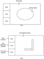
- FIG. 1 is a schematic diagram illustrating a horn page according to an embodiment of the present disclosure.
- the horn page can be displayed by the display component and the horn page can include a virtual button.
- the first touching operation may be a touching operation for the virtual button.
- a region corresponding to the virtual button is located in a center of the horn page, and the region's shape may be a circle as shown in FIG. 1 or may be set to another shape as needed.
- one or more regions may be disposed and parameters such as a position, a shape, an area and the like of the region may be adjusted as well.
- the touch component can receive a first touching operation for the horn page from a user, and generate a horn touch signal based on the first touching operation and output the horn touch signal to the controller and the response component.
- the first touching operation for the horn page may be a touching operation for the virtual button, for example, a press operation.
- the controller may send a signal to a horn (e.g., a horn of a vehicle) in a wireless or wired manner, so as to trigger the horn to honk.
- the controller can trigger the horn to honk based on the horn touch signal, and on the other hand, the response component can generate the first tactile response based on the horn touch signal while the horn is honking.
- the response component may include piezoelectric patches attached to edges of both sides of the display device, and the vibration of the piezoelectric patches can be controlled to generate a tactile response, so as to improve the user's sense of reality in operating the horn.
- visualized display can be performed for a button of a vehicle's horn to help a user to more visually determine a position of the button. Even in a dark environment, operations can be accurately performed. Further, according to the first touching operation for the horn page, the first tactile response is generated to improve the user's sense of reality in horn operation, such that the user can quickly determine, based on the first tactile response, that the display device has successfully received the first touching operation.
- a physical horn button may be disposed, such that a user may not only perform an operation for the horn page to trigger the horn to honk, but also perform an operation (e.g., pressing) for the physical horn button to trigger the horn to honk.
- a pressure sensor may be disposed in the display device as well to sense touch intensity of the first touching operation, such that the controller can control a honk volume of the horn based on the touch intensity. For example, the larger the touch intensity is, the larger the volume is, and the smaller the touch intensity is, the smaller the volume is. Therefore, a user can adjust the honk volume of the horn by controlling the touch intensity of the first touching operation, which is beneficial to control the horn flexibly.
- controller is further configured to:
- the touch component when the horn page is being displayed, can generate a horn touch signal carrying information of the touch intensity based on the received first touching operation.
- the controller can determine the touch intensity of the first touching operation, and compare the touch intensity with the touch intensity threshold. In a case that the touch intensity is greater than the touch intensity threshold, the controller can determine that the touch intensity is relatively large and the first touching operation is generally not inadvertently triggered, such that the horn can be triggered to honk. While in a case that the touch intensity is less than the touch intensity threshold, the controller can determine that the touch intensity is relatively small and the first touching operation may be inadvertently triggered in a high possibility, and therefore the controller does not trigger the horn to honk. When the touch intensity is equal to the touch intensity threshold, whether to trigger the horn to honk can be set based on needs. Thus, this way helps to prevent the horn from honking due to inadvertent touch of the user.
- the display device may include a touch effective region.
- the controller is further configured to:
- the display device may include the touch effective region.
- the touch effective region may correspond to a virtual button, and the touch effective region may include an edge, for example, an edge of the corresponding virtual button.
- the touch component can generate a horn touch signal carrying the position of the first touching operation based on the received first touching operation, such that the controller can determine the position of the first touching operation. For example, the controller can determine whether the position of the first touching operation is within the touch effective region. In a case that the position of the first touching operation is within the touch effective region, the controller may trigger the horn to honk. In a case that the position of the first touching operation is outside the touch effective region, the controller may not trigger the horn to honk. Therefore, this way helps to prevent the user from triggering the horn to honk due to inadvertently touching a region outside the touch effective region.
- the response component is further configured to generate visual feedback while the horn is honking.
- the response component can generate visual feedback while the horn is honking.
- a ripple diffusion pattern can be generated around the virtual button shown in FIG. 1 as visual feedback, thereby improving the user's sense of reality in horn operation.
- the controller is further configured to: in a duration of the first touching operation, control the horn to honk; and/or, at an end of the first touching operation, control the horn to stop honking.
- the controller in the duration of the first touching operation, for example, when the user continuously presses the virtual button in the horn page, the controller can keep sending signals to the horn of the vehicle to continuously trigger the horn to honk.
- the controller can stop sending signals to the horn of the vehicle, such that the horn can stop honking.
- the touch component is further configured to generate, according to a received first switching operation, a first switching touch signal, and send the first switching touch signal to the controller, where the first switching operation includes a touching operation for a seat adjustment identifier in a navigation bar displayed in the display component.
- the controller is further configured to control, according to the first switching touch signal, the display component to switch from displaying the horn page to displaying a seat adjustment page.
- the touch component is further configured to generate, according to a second touching operation for the seat adjustment page, an adjustment touch signal, and send the adjustment touch signal to the controller and the response component.
- the controller is further configured to adjust a position of a seat according to the adjustment touch signal.
- the response component is further configured to generate, according to the adjustment touch signal, a second tactile response while the position of the seat is being adjusted.
- FIG. 2 is a schematic diagram illustrating a seat adjustment page according to an embodiment of the present disclosure.
- a navigation bar in a page displayed by the display component, for example, at a left side of the page, a navigation bar may be displayed and the navigation bar may be provided with identifiers for switching, such as a horn identifier, a seat adjustment identifier and a voice call identifier.
- a first switching operation may refer to an operation for the seat adjustment identifier, for example, an operation of clicking the seat adjustment identifier.
- the display component When the display component displays the horn page, a user may click the seat adjustment identifier as a first switching operation.
- the touch component can generate a first switching touch signal based on the received first switching operation, and send the first switching touch signal to the controller.
- the controller can control the display component to switch from displaying the horn page to displaying the seat adjustment page according to the first switching touch signal.
- a seat pattern may be displayed in the seat adjustment page, and the second touching operation may include an operation of a user for the seat pattern, for example, dragging the seat pattern or clicking a backrest of the seat pattern and rotating the backrest.
- the touch component can generate an adjustment touch signal according to the second touching operation for the seat adjustment page, and send the adjustment touch signal to the controller and the response component.
- the controller can adjust a position of a seat according to the adjustment touch signal from the touch component, for example, adjusting a horizontal position of the seat, a seat backrest pitch angle and the like.
- the seat pattern can be dragged in the seat adjustment page to adjust the position of the seat in a horizontal direction, and the backrest can be rotated to adjust the backrest's angle of pitch.
- the response component can further generate a second tactile response based on the adjustment touch signal from the touch component, thereby improving the user's sense of reality in the seat adjustment process.
- One or more adjusted seats may include a driver seat or another seat, for example, a co-driver's seat, a seat for persons other than a driver and a co-driver, and the like. These seats can be adjusted separately or in a unified way, which can be selected and set as needed.
- the seat adjustment is usually performed by using a physical structure such as a mechanical switch, a physical toggle knob and the like, and these structures are usually located at a side of a seat or even under the seat, so it is inconvenient for the user to view, resulting in inaccurate control.
- a physical structure such as a mechanical switch, a physical toggle knob and the like
- virtualized display can be performed on one or more the keys for adjusting a seat, so as to help the user to visually see the adjustment keys and accurately adjust the seat.
- the second tactile response can be generated to improve the user's sense of reality for seat adjustment, such that the user can quickly determine based on the second tactile response that the display device has successfully received the second touching operation.
- the embodiments relating to the seat adjustment page in the present disclosure can be implemented on the basis of the horn page or independently of the horn page.
- the seat adjustment page may be displayed in a center of a steering wheel, and the horn may be still controlled by a physical structure.
- the horn page and the seat adjustment page may be displayed on the steering wheel at the same time, without any switching to display.
- a seat position of a seat is displayed in the seat adjustment page and the touch component is further configured to send the adjustment touch signal to the display component; and the display component is configured to change, according to the adjustment touch signal, the displayed seat position.
- the seat adjustment page may display the seat position of the seat, for example, a position of the seat in a horizontal direction (for example, being represented by a distance between the seat's backrest and the steering wheel), an angle of the seat's backrest and the like.
- the touch component can further send the adjustment touch signal to the display component, such that the display component can change the displayed seat position based on the adjustment touch signal. In this way, the user can visually determine a pose of the seat by watching, so as to accurately adjust the seat.
- the seat adjustment page is provided with at least one horizontal position adjustment bar.
- the touch component is configured to generate, according to the second touching operation for the horizontal position adjustment bar, a first adjustment touch signal, and transmit the first adjustment touch signal to the controller and the response component;
- the seat adjustment page is provided with at least one seat backrest angle adjustment bar
- FIG. 3A is a schematic diagram illustrating another seat adjustment page according to an embodiment of the present disclosure.
- the seat adjustment page may be provided with two horizontal position adjustment bars, and may also be provided with two seat backrest angle adjustment bars.
- a user can adjust a seat by operating the adjustment bars.
- a horizontal position adjustment bar' shape may be a straight line as shown in FIG. 3A , or may be set to another shape as needed.
- a seat backrest angle adjustment bar's shape may be an arc as shown in FIG. 3A , or may be set to another shape as needed.
- the touch component can generate a first adjustment touch signal, and send the first adjustment touch signal to the controller and the response component.
- the controller can adjust a horizontal position of the seat based on the first adjustment touch signal, and the response component can generate a tactile response of sliding friction based on the first adjustment touch signal while the horizontal position of the seat is being adjusted.
- the touch component can generate a second adjustment touch signal, and send the second adjustment touch signal to the controller and the response component.
- the controller can adjust an angle of pitch for the seat's backrest based on the second adjustment touch signal, and the response component can generate a tactile response of rotating friction based on the second adjustment touch signal while the seat's angle of pitch is being adjusted.
- Positions and the number of the adjustment bars may be as shown in FIG. 3A , or the positions may be adjusted as needed.
- FIG. 3B is a schematic diagram illustrating a seat adjustment process according to an embodiment of the present disclosure.
- FIG. 3C is a schematic diagram illustrating another seat adjustment process according to an embodiment of the present disclosure.
- a user may perform a second touching operation on a horizontal position adjustment bar, for example, sliding on the horizontal position adjustment bar to adjust a position of a seat.
- a horizontal position adjustment bar for example, sliding on the horizontal position adjustment bar to adjust a position of a seat.
- the user may slide leftward on the horizontal position adjustment bar to adjust the seat to move forward, and may slide rightward on the horizontal position adjustment bar to adjust the seat to move backward.
- sliding leftward on the horizontal position adjustment bar can adjust the seat to move forward.
- the second touching operation can be an operation of sliding along a straight line, and the response component can generate a tactile response of sliding friction based on the second touching operation.
- the user can accurately sense a degree of the sliding operation based on the tactile response without watching an operation on the display device, thus helping to prevent the user from distracting in a driving process and improving the driving safety.
- the user may perform a second touching operation on a seat backrest angle adjustment bar, for example, sliding on the seat backrest angle adjustment bar to adjust the position of the seat.
- a seat backrest angle adjustment bar for example, sliding on the seat backrest angle adjustment bar to adjust the position of the seat.
- the user may slide counterclockwise on the seat backrest angle adjustment bar to adjust the seat to tilt forward, and may slide clockwise on the seat backrest angle adjustment bar to adjust the seat to tilt backward.
- sliding clockwise on the seat backrest angle adjustment bar can adjust the seat to tilt backward.
- the second touching operation can be a rotating operation, and the response component can generate a tactile response of rotating friction based on the second touching operation.
- the user can accurately sense a degree of the rotating operation based on the tactile response without watching an operation on the display device, thus helping to prevent the user from distracting in a driving process and improving the driving safety.
- the number of horizontal position adjustment bar(s) may be one or two, and can also be set to be more as needed.
- the two horizontal position adjustment bars may be symmetrically arranged at the left and right sides of the seat adjustment page (e.g., the lower left corner and the lower right corner) as shown in FIG. 3A .
- a user may choose, based on needs, to perform an operation on the left horizontal position adjustment bar or the right horizontal position adjustment bar, which helps the user to flexibly choose a left or right hand for operation.
- the number of seat backrest angle adjustment bar(s) may be one or two, and can also be set to be more as needed.
- the two seat backrest angle adjustment bars may be symmetrically arranged at the left and right sides of the seat adjustment page (e.g., the upper left corner and the upper right corner) as shown in FIG. 3A .
- a user may choose, based on needs, to perform an operation on the left seat backrest angle adjustment bar or the right seat backrest angle adjustment bar, which helps the user to flexibly select choose the left or right hand for operation.
- the seat adjustment page is provided with a plurality of adjustment regions.
- the touch component is further configured to determine a target region where the second touching operation is located from the plurality of adjustment regions, and indicate to the controller that the second touching operation is located in the target region.
- the controller is configured to determine an adjustment speed proportion corresponding to the target region, determine an adjustment speed according to the adjustment speed proportion and the adjustment touch signal, and adjust the position of the seat according to the adjustment speed.
- a plurality of adjustment regions may be set in the seat adjustment page, and an adjustment speed corresponding to each adjustment region can be set.
- the horizontal position adjustment bar may be equally divided into left and right adjustment regions.
- the left half region may correspond to a larger adjustment speed proportion, for example, 4, and the right half region may correspond to a smaller adjustment speed proportion, for example, 2.
- the touch component can determine a target region where the sliding operation is located from the plurality of adjustment regions, and indicate to the controller that the sliding operation is in the target region.
- the controller can determine an adjustment speed proportion corresponding to the target region, determine an adjustment speed based on the adjustment speed proportion and the adjustment touch signal, and adjust the position of the seat based on the determined adjustment speed.
- the adjustment speed can be also affected by a speed of the second touching operation, for example, the faster the speed of the second touching operation is, the faster the adjustment speed is.
- the adjustment speed proportion the following descriptions are made with a case that the speed at which the user performs the second touching operation remains unchanged.
- the user's sliding speed can be lcm/s
- the controller can determine that an adjustment speed proportion corresponding to the right half region is 2.
- the horizontal position of the seat can be adjusted at a speed of 2cm/s.
- the controller can determine that an adjustment speed proportion corresponding to the left half region is 4.
- the horizontal position of the seat can be adjusted at a speed of 4 cm/s.
- the touch component is further configured to record a length of time during which no operation for the seat adjustment page is received, and in response to determining that the recorded length of time is greater than a first predetermined time length, send a first expiration signal to the controller; and the controller is further configured to control, according to the first expiration signal, the display component to switch from displaying the seat adjustment page to displaying the horn page.
- the touch component can record a length of time in which no operation is received.
- a first expiration signal can be sent to the controller, indicating that the user would not adjust the seat in a period of time.
- the controller can automatically control the display component to switch from displaying the seat adjustment page to displaying the horn page, so as to restore a function that a page displayed by the display device serves as a virtual button of a horn.
- the touch component is further configured to generate, according to a received second switching operation, a second switching touch signal, and send the second switching touch signal to the controller, where the second switching operation includes a touching operation for a voice call identifier in a navigation bar displayed by the display component;
- FIG. 4 is a schematic diagram illustrating a voice call page according to an embodiment of the present disclosure.
- a navigation bar in a page displayed by the display device, for example, at a left side of the page, a navigation bar may be displayed and the navigation bar may be provided with identifiers for switching, such as a horn identifier, a seat adjustment identifier and a voice call identifier.
- a second switching operation may refer to an operation for the voice call identifier, for example, an operation of clicking the voice call identifier.
- a user may click the voice call identifier as a second switching operation.
- the touch component can generate a second switching touch signal based on the received second switching operation, and send the second switching touch signal to the controller.
- the controller can control the display component to switch from displaying the horn page to displaying the voice call page according to the second switching touch signal.
- icons of contacts and dial keys may be displayed, and the third touching operation may include operations such as a user selecting a contact, clicking a dial key and the like.
- the touch component can generate a call touch signal according to the third touching operation for the voice call page, and send the call touch signal to the controller and the response component.
- the controller can trigger a voice call based on the call touch signal from the touch component, for example, dialing the selected contact's number to initiate a voice call.
- the response component can generate a third tactile response based on the call touch signal from the touch component while the voice call is being triggered, so as to improve the user's sense of reality for the voice call process.
- voice call keys are usually located in a central control region in right front of a driver, when the driver wants to initiate a voice call, the driver needs to turn his field of view to the right front to see and operate the voice call keys. In this case, the driver basically loses his field of view in a vehicle travelling direction, leading to significant potential safety hazard.
- a voice call page may be displayed on a steering wheel.
- the user can perform an operation directly on the steering wheel without adjusting the gaze direction, thus reducing the potential safety hazard.
- the third tactile response can be generated to improve the user's sense of reality for a voice call operation, such that the user can quickly determine, based on the third tactile response, that the display device has successfully received the third touching operation.
- the embodiments relating to the voice call page in the present disclosure can be implemented on the basis of the horn page or independently of the horn page.
- the voice call page may be displayed in a center of a steering wheel, and the horn may be still controlled by a physical structure.
- the horn page and the voice call page may be displayed on the steering wheel at the same time, without any switching to display.
- the voice call page displays at least a selection region and a call region
- the third touching operation includes a selection touching operation for the selection region and a call touching operation for the call region
- a selection region and a call region may be displayed in the voice call page.
- the selection region may include one or more selection keys and contacts
- the call region may include one or more call keys.
- the selection keys' shapes may be circles and the call keys' shapes may be rectangles. The keys may also be in other shapes as needed.
- the touch component can generate, according to the received selection touching operation, a selection touch signal, and send the selection touch signal to the display component and the response component.
- the display component can select a target contact in a displayed picture based on the selection touch signal, and the response component can generate a tactile response based on the selection touch signal, while the display component is performing the target contact selection.
- the touch component can generate, according to the received call touching operation, a call touch signal, and send the call touch signal to the control component and the response component.
- the control component can call the target contact based on the call touch signal
- the response component can generate a tactile response based on the call touch signal, while the target contact is being called.
- the user may perform an operation on the selection region to select a target contact, for example, sliding counterclockwise or clockwise in the virtual button shown in FIG. 4 to select a target contact from a plurality of contacts.
- the selected target contact may be contact 3 shown in FIG. 4 and displayed in a highlighted form.
- the target contact can be called by performing an operation on the call region, for example, by clicking a call key to trigger dialing a number corresponding to the target contact.
- the voice call page may display an emergency call region.
- the touch component can be further configured to generate, according to a touching operation for the emergency call region, an emergency call signal, and send the emergency call signal to the controller and the response component.
- the controller can be further configured to call, according to the emergency call signal, a predetermined emergency contact, and the response component can generate a tactile response while the emergency contact is being called.
- the voice call page may further display an emergency call region, for example, an emergency call button under the call region as displayed in FIG. 4 .
- a user can perform a touching operation on the emergency call region to call an emergency contact.
- the emergency contact's number may be pre-stored and can be dialed without making selection.
- the emergency contact's number may include, but is not limited to 110, 119, 120 and the like, which can be set based on needs.
- the call region includes a central region and an edge region.
- the touch component is configured to generate a first call touch signal according to a call touching operation for the central region, generate a second call touch signal according to a call touching operation for the edge region, and send the first call touch signal and the second call touch signal to the response component.
- the response component is further configured to generate, according to the first call touch signal and the second call touch signal, different tactile responses respectively.
- the response component can be controlled to generate different tactile responses.
- a tactile response intensity of the edge region may be relatively large, and a tactile response intensity of the central region may be relatively small.
- the tactile response intensity may be reflected by parameters such as a vibration frequency and a vibration amplitude and the like of a piezoelectric patch.
- the vibration frequency and the vibration amplitude can be positively correlated with the response intensity respectively.
- the touch component can generate the second call touch signal, and send the second call touch signal to the controller and the response component.
- the controller does not trigger calling the target contact, and the response component can generate a relatively strong vibration, such that the user can feel a relatively strong tactile response and experience a feeling of edges.
- the touch component When the user presses the central region, the touch component can generate the first call touch signal, and send the first call touch signal to the controller and the response component.
- the controller can trigger calling the target contact, and the response component can generate a relatively mild vibration, such that the user can feel a relatively mild tactile response and experience pressing touch.
- the user can accurately identify the touched region based on the tactile response, so as to memorize positions of the edge region and the central region in the call region. Subsequently, the user can relatively accurately operate the central region to trigger a call without directly watching the page. Therefore, the operation efficiency and accuracy can be improved, and on the other hand, the user can be prevented from being distracted during driving, thus improving the driving safety.
- the selection touching operation includes a clockwise touching operation or a counterclockwise touching operation
- the response component is configured to generate a tactile response with a sense of pause-move while the display component is performing the target contact selection.
- the response component can generate a tactile response with a sense of pause-move based on the second call touch signal.
- the selection region can include different radii and response intensities corresponding to adjacent radii are different.
- a tactile response intensity may be reflected by parameters such as a vibration frequency and a vibration amplitude and the like of a piezoelectric patch.
- the vibration frequency and the vibration amplitude can be positively correlated with the response intensity.
- finger(s) of the user may pass through different radii and feel a tactile response with varying intensities, leading to a sense of pause-move.
- the user can accurately determine the rotated angle based on the tactile response, so as to accurately perform an operation without directly watching the page. Therefore, the operation efficiency and accuracy can be improved, and on the other hand, the user can be prevented from being distracted during driving, thus improving the drive safety.
- the touch component is further configured to record a length of time in which no operation for the voice call page is received, and in response to determining that the recorded length of time is greater than a second predetermined time length, send a second expiration signal to the controller.
- the controller is further configured to control, according to the second expiration signal, the display component to switch from displaying the voice call page to displaying the horn page.
- the touch component can record a length of time in which no operation is received. In a case that the recorded length of time is greater than the second predetermined time length, the second expiration signal can be sent to the controller, indicating that the user would not make a voice call in a period of time.
- the controller can automatically control the display component to switch from displaying the voice call page to displaying the horn page, so as to restore a function that a page displayed by the display device serves as a virtual button of a horn.
- the user may also click a horn identifier manually as needed, such that the display device can switch from displaying the voice call page to displaying the horn page.
- the present disclosure further provides embodiments of a method of controlling the display device.
- FIG. 5A is a schematic flowchart illustrating a method of controlling a display device according to an embodiment of the present disclosure.
- the display device in this embodiment may be applied to a steering wheel, for example, a steering wheel of a vehicle, a ship, and an airplane and the like.
- a steering wheel may be disposed in the vehicle and the display device may be disposed on the steering wheel, for example, in the exact center of the steering wheel.
- the display device can include a display component (e.g., a display panel), a touch component (e.g., a touch panel), a response component, a controller and the like.
- Various components can communicate with each other, and the controller can communicate with each component.
- the method may include the following steps.
- a horn page is displayed in the display device.
- a horn is triggered to honk according to a first touching operation for the horn page, and a first tactile response is generated while the horn is honking.
- triggering the horn to honk according to the first touching operation for the horn page includes: according to a horn touch signal generated by a touch component, determining touch intensity of the first touching operation; and in response to determining that the touch intensity is greater than or equal to a touch intensity threshold, triggering the horn to honk.
- the display device includes a touch effective region
- triggering the horn to honk according to the first touching operation for the horn page includes: according to the horn touch signal, determining a position of the first touching operation; in response to determining that the position of the first touching operation is in the touch effective region, triggering the horn to honk.
- the method further includes: generating visual feedback while the horn is honking.
- the method further includes, in a duration of the first touching operation, controlling the horn to honk; and/or at the end of the first touching operation, controlling the horn to stop honking.
- FIG. 5B is a schematic flowchart of controlling a horn to honk according to an embodiment of the present disclosure.
- the display device can start a software and perform self-check to determine whether a system runs normally. In a case that the system does not run normally, the display device can exit the software and try to remove system faults. In a case that the system runs normally, it can be further determined whether the currently-displayed page is the horn page. In response to determining that the page is not the horn page, a user can perform a switching operation on a navigation bar as needed, such that the horn page can be switched to and displayed. In response to determining that the page is the horn page, a virtual horn button can be displayed in the page.
- a touch event for the displayed horn button occurs can be determined. In a case that the determination indicates "no", the display device can continue waiting for receiving a touch event. In a case that the determination indicates "yes”, the horn can be triggered to honk, and a tactile response and a visual response can be generated, for example, vibration is generated and an acoustic wave diffusion pattern is displayed. At the end of the touch event, the horn can stop honking, and the corresponding tactile response and visual response can be stopped, and the horn page can be restored to an initial state.
- FIG. 6A is a schematic flowchart illustrating another method of controlling a display device according to an embodiment of the present disclosure. As shown in FIG. 6A , the method may further include the following steps.
- the horn page is switched to a seat adjustment page, where the first switching operation includes a touching operation for a seat adjustment identifier in a navigation bar displayed by the display device.
- step S602 according to a second touching operation for the seat adjustment page, a position of a seat is adjusted, and a second tactile response is generated while the position of the seat is being adjusted.
- the seat adjustment page displays a seat position of the seat and the method may include: according to the second touching operation, changing the displayed seat position.
- the seat adjustment page is provided with a plurality of adjustment regions, and adjusting the position of the seat according to the second touching operation for the seat adjustment page can include:
- the method can further include:
- FIG. 6B is a schematic flowchart of adjusting a seat according to an embodiment of the present disclosure.
- the display device can start a software and perform self-check to determine whether a system runs normally. In a case that the system does not run normally, the display device can exit the software and try to remove system faults. In a case that the system runs normally, it can be further determined whether the currently-displayed page is the seat adjustment page. In response to determining that the page is not the seat adjustment page, a user can perform a switching operation on a navigation bar as needed to switch to displaying the seat adjustment page. In response to determining that the page is the seat adjustment page, a seat pattern and four adjustment bars can be displayed in the page, for example, as shown in FIG. 3A .
- a touch event for the adjustment bars can be determined. In a case that a touch event occurs, whether the touch event is a touch event for a horizontal position adjustment bar or a seat backrest angle adjustment bar can be determined further.
- an adjustment speed proportion corresponding to a region where a touching position is located can be further determined.
- regions may be divided into two types, a normal speed region or a fast speed region.
- a seat In response to determining that the touching position is in a normal speed region, a seat may be controlled to move forward at a normal speed, and visual feedback and tactile feedback of moving the seat forward at a normal speed can be generated in the horizontal position adjustment bar. In response to determining that the touching position is in a fast speed region, the seat may be controlled to move forward at a fast speed, and visual feedback and tactile feedback of moving the seat forward quickly can be generated in the horizontal position adjustment bar.
- the adjustment speed proportion corresponding to the region where the touching position is located can be determined as well.
- the seat In response to determining that the touching position is in a normal speed region, the seat may be controlled to move backward at a normal speed, and visual feedback and tactile feedback of moving the seat backward at a normal speed can be generated in the horizontal position adjustment bar. In response to determining that the touching position is in a fast speed region, the seat may be controlled to move backward at a fast speed, and visual feedback and tactile feedback of moving the seat backward quickly can be generated in the horizontal position adjustment bar.
- a direction of the touching operation indicates forward adjustment, namely, adjusting a backrest of a seat to tilt forward.
- an adjustment speed proportion corresponding to a region where a touching position is located can be further determined.
- regions may be divided into two types, a normal speed region and a fast speed region.
- the backrest of the seat may be controlled to tilt forward at a normal speed, and visual feedback and tactile feedback of tilting the seat backrest forward at a normal speed can be generated in the seat backrest angle adjustment bar.
- the backrest of the seat may be controlled to tilt forward at a fast speed, and visual feedback and tactile feedback of tilting the seat backrest forward quickly can be generated in the seat backrest angle adjustment bar.
- an adjustment speed proportion corresponding to a region where the touching position is located can be determined as well.
- the backrest of the seat may be controlled to tilt backward at a normal speed, and visual feedback and tactile feedback of tilting the seat backrest backward at a normal speed can be generated in the seat backrest angle adjustment bar.
- the backrest of the seat may be controlled to tilt backward at a fast speed, and visual feedback and tactile feedback of tilting the seat backrest backward quickly can be generated in the seat backrest angle adjustment bar.
- FIG. 7A is a schematic flowchart illustrating a method of controlling a display device according to an embodiment of the present disclosure. As shown in FIG. 7A , the method may further include:
- the voice call page displays at least a selection region and a call region
- the third touching operation includes a selection touching operation for the selection region and a call touching operation for the call region.
- triggering the voice call and generating the third tactile response while the voice call is being triggered include:
- the call region includes a central region and an edge region.
- Generating the tactile response while the target contact is being called includes: according to a call touching operation for the central region and a call touching operation for the edge region, generating different tactile responses respectively.
- the selection touching operation includes a clockwise touching operation or a counterclockwise touching operation
- generating the tactile response while the target contact is being selected includes: generating a tactile response with a sense of pause-move while the target contact is being selected.
- the method further includes:
- FIG. 7B is a schematic flowchart of a voice call according to an embodiment of the present disclosure.
- the display device can start a software and perform self-check to determine whether a system runs normally. In a case that the system does not run normally, the display device can exit the software and try to remove system faults. In a case that the system runs normally, it can be further determined whether the currently-displayed page is the voice call page. In response to determining that the page is not the voice call page, a user can perform a switching operation on a navigation bar as needed to switch to displaying the voice call page. In response to determining that the page is the voice call page, a selection region and a call region can be displayed in the page, for example, as shown in FIG. 4 .
- a touching operation for the voice call page occurs can be determined. In a case that no touching operations occur, the voice call process can be ended; and in a case that a touching operation occurs, it can be determined whether the touching operation occurs in a selection region. In response to determining that the touching operation occurs in the selection region, a selected target contact can be determined, and a tactile response with a sense of pause-move can be generated during the selection. In response to determining that the touching operation does not occur in the selection region, it can be determined whether the touching operation occurs in a call region. In response to determining that the touching operation does not occur in the call region, the voice call process can be ended.
- a relatively strong vibration may be generated as a tactile response, enabling the user to experience a feeling of edges.
- a relatively mild vibration may be generated as a tactile response to enable the user to experience pressing touch, and a call to an emergency contact may be made.
- a relatively strong vibration may be generated as a tactile response, enabling the user to experience a feeling of edges.
- a relatively mild vibration may be generated as a tactile response to enable the user to experience pressing touch, and a call to the selected target contact may be made.
- An embodiment of the present disclosure further provides a non-transitory computer readable storage medium, storing a computer program.
- the computer programs are executed by a processor to perform the steps of the method of any one of the above embodiments.
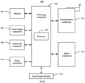
- FIG. 8 is a block diagram of a display device 800 according to an embodiment of the present disclosure.
- the display device 800 may be a mobile phone, a computer, a digital broadcast terminal, a message transceiver, a game console, a tablet device, a medical device, a fitness device, a personal digital assistant, and the like.
- the display device 800 may include one or more of the following components: a processing component 802, a memory 804, a power supply component 806, a multimedia component 808, an audio component 810, an input/output (I/O) interface 812, a sensor component 814 and a communication component 816.
- the processing component 802 generally controls overall operations of the display device 800, such as operations associated with display, phone calls, data communications, camera operations, and recording operations.
- the processing component 802 may include one or more processors 820 to execute instructions to complete all or part of the steps of the above methods.
- the processing component 802 may include one or more modules which facilitate the interaction between the processing component 802 and other components.
- the processing component 802 may include a multimedia module to facilitate the interaction between the multimedia component 808 and the processing component 802.
- the memory 804 is configured to store various types of data to support the operation of the display device 800. Examples of such data include instructions for any application program or method operated on the display device 800, contact data, phonebook data, messages, pictures, videos, and so on.
- the memory 804 may be implemented by any type of volatile or non-volatile storage devices or a combination thereof, such as a Static Random Access Memory (SRAM), an Electrically Erasable Programmable Read-Only Memory (EEPROM), an Erasable Programmable Read-Only Memory (EPROM), a Programmable Read-Only Memory (PROM), a Read-Only Memory (ROM), a magnetic memory, a flash memory, a magnetic or compact disk.
- SRAM Static Random Access Memory
- EEPROM Electrically Erasable Programmable Read-Only Memory
- EPROM Erasable Programmable Read-Only Memory
- PROM Programmable Read-Only Memory
- ROM Read-Only Memory
- the power supply component 806 supplies power for different components of the display device 800.
- the power supply component 806 may include a power supply management system, one or more power supplies, and other components associated with generating, managing and distributing power for the display device 800.
- the multimedia component 808 includes a screen that provides an output interface between the display device 800 and a user.
- the screen may include a liquid crystal display (LCD) and a touch panel (TP). If the screen includes a touch panel, the screen may be implemented as a touch screen to receive input signals from the user.
- the touch panel includes one or more touch sensors to sense touches, slides, and gestures on the touch panel. The touch sensor may not only sense the boundary of touch or slide actions but also detect the duration and pressure associated with touch or slide operations.
- the multimedia component 808 includes a front camera and/or a rear camera. When the display device 800 is in an operation mode, such as a shooting mode or a video mode, the front camera and/or the rear camera may receive external multimedia data. Each of the front and rear cameras may be a fixed optical lens system or have a focal length and an optical zoom capability.
- the audio component 810 is configured to output and/or input audio signals.
- the audio component 810 includes a microphone (MIC) configured to receive an external audio signal when the display device 800 is in an operation mode, such as a call mode, a recording mode, and a voice recognition mode.
- the received audio signal may be further stored in the memory 804 or transmitted via the communication component 816.
- the audio component 810 also includes a loudspeaker for outputting an audio signal.
- the I/O interface 812 provides an interface between the processing component 802 and a peripheral interface module which may be a keyboard, a click wheel, a button, or the like. These buttons may include, but are not limited to a home button, a volume button, a start button, and a lock button.
- the sensor component 814 includes one or more sensors for providing a status assessment in various aspects to the display device 800.
- the sensor component 814 may detect an on/off state of the display device 800, and the relative positioning of components, for example, the component is a display and a keypad of the display device 800.
- the sensor component 814 may also detect a change in position of the display device 800 or a component of the display device 800, the presence or absence of a user in contact with the display device 800, the orientation or acceleration/deceleration of the display device 800 and a change in temperature of the display device 800.
- the sensor component 814 may include a proximity sensor configured to detect the presence of nearby objects without any physical contact.
- the sensor component 814 may also include a light sensor, such as a CMOS or CCD image sensor, for use in imaging applications.
- the sensor component 814 may also include an acceleration sensor, a gyro sensor, a magnetic sensor, a pressure sensor, or a temperature sensor.
- the communication component 816 is configured to facilitate wired or wireless communication between the display device 800 and other devices.
- the display device 800 may access a wireless network based on a communication standard, such as WiFi, 2G or 3G, or 4G LTE or 5G NR or a combination thereof.
- the communication component 816 receives broadcast signals or broadcast associated information from an external broadcast management system via a broadcast channel.
- the communication component 816 also includes a near field communication (NFC) module to facilitate short range communication.
- the NFC module may be implemented based on a radio frequency identification (RFID) technology, an infrared data association (IrDA) technology, an ultra wide band (UWB) technology, a Bluetooth (BT) technology, and other technologies.
- RFID radio frequency identification
- IrDA infrared data association
- UWB ultra wide band
- BT Bluetooth
- the display device 800 may be implemented by one or more application specific integrated circuits (ASICs), digital signal processors (DSPs), digital signal processing devices (DSPDs), programmable logic devices (PLDs), a field programmable gate array (FPGA), a controller, a microcontroller, a microprocessor or other electronic elements for performing the above methods.
- ASICs application specific integrated circuits
- DSPs digital signal processors
- DSPDs digital signal processing devices
- PLDs programmable logic devices
- FPGA field programmable gate array
- controller a microcontroller, a microprocessor or other electronic elements for performing the above methods.
- non-transitory computer readable storage medium including instructions, such as a memory 804 including instructions, where the instructions are executable by the processor 820 of the display device 800 to perform the method as described above.
- the non-transitory computer readable storage medium may be a read only access memory (ROM), a random access memory (RAM) CD-ROM, magnetic tape, floppy disk, or optical data storage device or the like.
Landscapes
- Engineering & Computer Science (AREA)
- Chemical & Material Sciences (AREA)
- Combustion & Propulsion (AREA)
- Transportation (AREA)
- Mechanical Engineering (AREA)
- Position Input By Displaying (AREA)
- User Interface Of Digital Computer (AREA)
Applications Claiming Priority (1)
| Application Number | Priority Date | Filing Date | Title |
|---|---|---|---|
| PCT/CN2021/127190 WO2023070472A1 (fr) | 2021-10-28 | 2021-10-28 | Appareil d'affichage et son procédé de commande |
Publications (1)
| Publication Number | Publication Date |
|---|---|
| EP4339924A1 true EP4339924A1 (fr) | 2024-03-20 |
Family
ID=86160333
Family Applications (1)
| Application Number | Title | Priority Date | Filing Date |
|---|---|---|---|
| EP21961837.8A Pending EP4339924A1 (fr) | 2021-10-28 | 2021-10-28 | Appareil d'affichage et son procédé de commande |
Country Status (3)
| Country | Link |
|---|---|
| EP (1) | EP4339924A1 (fr) |
| CN (1) | CN116568584A (fr) |
| WO (1) | WO2023070472A1 (fr) |
Family Cites Families (5)
| Publication number | Priority date | Publication date | Assignee | Title |
|---|---|---|---|---|
| CN204506977U (zh) * | 2015-04-10 | 2015-07-29 | 李佳民 | 一种新型汽车方向盘 |
| CN205113412U (zh) * | 2015-07-20 | 2016-03-30 | 比亚迪股份有限公司 | 车辆转向盘和具有其的车辆 |
| US10583855B2 (en) * | 2017-09-05 | 2020-03-10 | Byton Gmbh | Steering device for a vehicle, in particular an electric vehicle |
| CN113002614A (zh) * | 2019-12-19 | 2021-06-22 | 上海汽车集团股份有限公司 | 一种方向盘及汽车 |
| CN111625088A (zh) * | 2020-04-28 | 2020-09-04 | 思特沃克软件技术(北京)有限公司 | 车载系统控制方法及方向盘 |
-
2021
- 2021-10-28 WO PCT/CN2021/127190 patent/WO2023070472A1/fr active Application Filing
- 2021-10-28 EP EP21961837.8A patent/EP4339924A1/fr active Pending
- 2021-10-28 CN CN202180003168.6A patent/CN116568584A/zh active Pending
Also Published As
| Publication number | Publication date |
|---|---|
| WO2023070472A1 (fr) | 2023-05-04 |
| CN116568584A (zh) | 2023-08-08 |
Similar Documents
| Publication | Publication Date | Title |
|---|---|---|
| EP3575950B1 (fr) | Procédé de commande de terminal, dispositif et support d'enregistrement lisible par ordinateur | |
| US10082873B2 (en) | Method and apparatus for inputting contents based on virtual keyboard, and touch device | |
| JP6553719B2 (ja) | 画面分割表示方法および装置 | |
| KR101785230B1 (ko) | 풀스크린 싱글핸드 조작 방법, 장치, 프로그램 및 기록매체 | |
| EP3244396A1 (fr) | Procédé et afficheur à écran divisé | |
| CN110662095B (zh) | 投屏处理方法、装置、终端及存储介质 | |
| EP3099040B1 (fr) | Procédé de traitement de maniement d'un bouton de mode avec une seule main, appareil et dispositif électronique | |
| US20180039403A1 (en) | Terminal control method, terminal, and storage medium | |
| CN107193553B (zh) | 按键控制方法及装置 | |
| KR20150025616A (ko) | 이동 단말기 | |
| CN108073328B (zh) | 触摸响应方法及装置 | |
| CN107885418B (zh) | 终端、分屏显示方法及装置 | |
| KR20130090965A (ko) | 이동 단말기 및 그 제어방법 | |
| CN112463084A (zh) | 分屏显示方法、装置、终端设备及计算机可读存储介质 | |
| KR20140063060A (ko) | 투명 표시부 운용 방법 및 이를 지원하는 단말기 | |
| CN111522498A (zh) | 触控响应方法、装置及存储介质 | |
| KR101398171B1 (ko) | 이동 단말기 | |
| EP4339924A1 (fr) | Appareil d'affichage et son procédé de commande | |
| KR102258742B1 (ko) | 터치신호의 처리방법, 장치 및 매체 | |
| CN110597443B (zh) | 日历显示方法、装置及介质 | |
| KR20140066676A (ko) | 이동 단말기 | |
| CN111273979A (zh) | 信息处理方法、装置及存储介质 | |
| KR101706941B1 (ko) | 이동 단말기 및 그를 이용한 퀵 액세스 동작 제어 방법 | |
| EP4134793A1 (fr) | Procédé et appareil de commande de fonction d'entrée et support d'enregistrement | |
| CN114035722A (zh) | 应用程序的交互方法、装置及介质 |
Legal Events
| Date | Code | Title | Description |
|---|---|---|---|
| STAA | Information on the status of an ep patent application or granted ep patent |
Free format text: STATUS: THE INTERNATIONAL PUBLICATION HAS BEEN MADE |
|
| PUAI | Public reference made under article 153(3) epc to a published international application that has entered the european phase |
Free format text: ORIGINAL CODE: 0009012 |
|
| STAA | Information on the status of an ep patent application or granted ep patent |
Free format text: STATUS: REQUEST FOR EXAMINATION WAS MADE |
|
| 17P | Request for examination filed |
Effective date: 20231214 |
|
| AK | Designated contracting states |
Kind code of ref document: A1 Designated state(s): AL AT BE BG CH CY CZ DE DK EE ES FI FR GB GR HR HU IE IS IT LI LT LU LV MC MK MT NL NO PL PT RO RS SE SI SK SM TR |