EP4339447A1 - Hydraulische maschine - Google Patents
Hydraulische maschine Download PDFInfo
- Publication number
- EP4339447A1 EP4339447A1 EP22807275.7A EP22807275A EP4339447A1 EP 4339447 A1 EP4339447 A1 EP 4339447A1 EP 22807275 A EP22807275 A EP 22807275A EP 4339447 A1 EP4339447 A1 EP 4339447A1
- Authority
- EP
- European Patent Office
- Prior art keywords
- flow path
- runner
- vane
- hydraulic machine
- stay
- Prior art date
- Legal status (The legal status is an assumption and is not a legal conclusion. Google has not performed a legal analysis and makes no representation as to the accuracy of the status listed.)
- Pending
Links
Images


Classifications
-
- F—MECHANICAL ENGINEERING; LIGHTING; HEATING; WEAPONS; BLASTING
- F03—MACHINES OR ENGINES FOR LIQUIDS; WIND, SPRING, OR WEIGHT MOTORS; PRODUCING MECHANICAL POWER OR A REACTIVE PROPULSIVE THRUST, NOT OTHERWISE PROVIDED FOR
- F03B—MACHINES OR ENGINES FOR LIQUIDS
- F03B3/00—Machines or engines of reaction type; Parts or details peculiar thereto
- F03B3/02—Machines or engines of reaction type; Parts or details peculiar thereto with radial flow at high-pressure side and axial flow at low-pressure side of rotors, e.g. Francis turbines
-
- F—MECHANICAL ENGINEERING; LIGHTING; HEATING; WEAPONS; BLASTING
- F03—MACHINES OR ENGINES FOR LIQUIDS; WIND, SPRING, OR WEIGHT MOTORS; PRODUCING MECHANICAL POWER OR A REACTIVE PROPULSIVE THRUST, NOT OTHERWISE PROVIDED FOR
- F03B—MACHINES OR ENGINES FOR LIQUIDS
- F03B13/00—Adaptations of machines or engines for special use; Combinations of machines or engines with driving or driven apparatus; Power stations or aggregates
- F03B13/08—Machine or engine aggregates in dams or the like; Conduits therefor, e.g. diffusors
-
- F—MECHANICAL ENGINEERING; LIGHTING; HEATING; WEAPONS; BLASTING
- F03—MACHINES OR ENGINES FOR LIQUIDS; WIND, SPRING, OR WEIGHT MOTORS; PRODUCING MECHANICAL POWER OR A REACTIVE PROPULSIVE THRUST, NOT OTHERWISE PROVIDED FOR
- F03B—MACHINES OR ENGINES FOR LIQUIDS
- F03B11/00—Parts or details not provided for in, or of interest apart from, the preceding groups, e.g. wear-protection couplings, between turbine and generator
- F03B11/02—Casings
-
- F—MECHANICAL ENGINEERING; LIGHTING; HEATING; WEAPONS; BLASTING
- F03—MACHINES OR ENGINES FOR LIQUIDS; WIND, SPRING, OR WEIGHT MOTORS; PRODUCING MECHANICAL POWER OR A REACTIVE PROPULSIVE THRUST, NOT OTHERWISE PROVIDED FOR
- F03B—MACHINES OR ENGINES FOR LIQUIDS
- F03B3/00—Machines or engines of reaction type; Parts or details peculiar thereto
- F03B3/12—Blades; Blade-carrying rotors
- F03B3/125—Rotors for radial flow at high-pressure side and axial flow at low-pressure side, e.g. for Francis-type turbines
-
- F—MECHANICAL ENGINEERING; LIGHTING; HEATING; WEAPONS; BLASTING
- F03—MACHINES OR ENGINES FOR LIQUIDS; WIND, SPRING, OR WEIGHT MOTORS; PRODUCING MECHANICAL POWER OR A REACTIVE PROPULSIVE THRUST, NOT OTHERWISE PROVIDED FOR
- F03B—MACHINES OR ENGINES FOR LIQUIDS
- F03B3/00—Machines or engines of reaction type; Parts or details peculiar thereto
- F03B3/16—Stators
- F03B3/18—Stator blades; Guide conduits or vanes, e.g. adjustable
- F03B3/186—Spiral or volute casings
-
- F—MECHANICAL ENGINEERING; LIGHTING; HEATING; WEAPONS; BLASTING
- F05—INDEXING SCHEMES RELATING TO ENGINES OR PUMPS IN VARIOUS SUBCLASSES OF CLASSES F01-F04
- F05B—INDEXING SCHEME RELATING TO WIND, SPRING, WEIGHT, INERTIA OR LIKE MOTORS, TO MACHINES OR ENGINES FOR LIQUIDS COVERED BY SUBCLASSES F03B, F03D AND F03G
- F05B2250/00—Geometry
-
- Y—GENERAL TAGGING OF NEW TECHNOLOGICAL DEVELOPMENTS; GENERAL TAGGING OF CROSS-SECTIONAL TECHNOLOGIES SPANNING OVER SEVERAL SECTIONS OF THE IPC; TECHNICAL SUBJECTS COVERED BY FORMER USPC CROSS-REFERENCE ART COLLECTIONS [XRACs] AND DIGESTS
- Y02—TECHNOLOGIES OR APPLICATIONS FOR MITIGATION OR ADAPTATION AGAINST CLIMATE CHANGE
- Y02E—REDUCTION OF GREENHOUSE GAS [GHG] EMISSIONS, RELATED TO ENERGY GENERATION, TRANSMISSION OR DISTRIBUTION
- Y02E10/00—Energy generation through renewable energy sources
- Y02E10/20—Hydro energy
Definitions
- the present invention relates to a hydraulic machine, such as a small hydraulic power generation apparatus, used in a power generation apparatus that is required to have high power generation efficiency.
- thermal power generation In recent years, reduction of carbon dioxide emissions has become a global challenge. For example, most of the world's power generation amount is covered by thermal power generation, but it is expected to increase the ratio of power generation using natural energy such as hydraulic power, geothermal power, and solar power from thermal power in order to reduce carbon dioxide emissions.
- Power generation using water channels, factory effluents, and the like has smaller output fluctuation with time than solar power generation, enables stable power generation, and is excellent in facility utilization rate.
- it is a solution to power loss due to long-distance power transmission which is a problem in the case of hydraulic power generation with a large dam.
- hydraulic power generation what is called small hydraulic power generation
- Patent Document 1 discloses a multifunctional inclined power generation apparatus that uses rotational energy obtained by passing water through a cylinder having a spiral plate closely attached to the inside thereof for power generation.
- Patent Document 2 discloses a hydraulic machine including: a casing including a plurality of stay vanes disposed over a circumferential direction, a plurality of inflow direction adjusting vanes disposed on an upstream side of each stay vane and defining an inflow direction of water flowing into each stay vane, and a plurality of guide vanes to which the water passing through the stay vanes is guided; and a runner including a plurality of runner vanes and rotationally driven by the water passing through the guide vanes.
- the conventional hydraulic power generation apparatus has a relationship that the larger the size, the higher the power generation efficiency, and the smaller the size, the lower the power generation efficiency.
- Patent Document 1 describes that the number of stages of the spiral plate is increased or the diameter of the cylindrical body is increased in order to increase power generation efficiency, and suggests that an apparatus having high power generation efficiency is likely to be increased in size. Therefore, in a case where it is attempted to secure a certain amount or more of power generation in an area where a flow rate and an elevation difference are likely to be small, such as a non-mountainous area, even if a large high-efficiency power generation apparatus is applied, the power generation efficiency decreases, which is not appropriate.
- the power generation apparatus is large, an installation place having a predetermined size and a large-scale construction are required, and thus it is desirable that the power generation efficiency is excellent while the size is appropriate.
- Patent Document 2 describes that an inflow direction adjusting vane and a guide vane are provided inside a casing, a disposing position and a disposing direction of the inflow direction adjusting vane are adjusted, and an opening degree of the guide vane is adjusted in order to increase power generation efficiency of a hydraulic machine.
- an increase in the number of types of blades inside the casing or an increase in the complexity of the shape may increase the manufacturing cost and the maintenance burden, or make it difficult to downsize the apparatus.
- the present invention has been made in view of such circumstances, and an object thereof is to provide a hydraulic machine that allows water to smoothly flow inside a flow path and is excellent in power generation efficiency. Another object of the present invention is to provide a hydraulic machine having a uniform flow rate of water inside a flow path and excellent power generation efficiency.
- a hydraulic machine of the present invention is a hydraulic machine including: a casing; and a runner rotatably disposed in a central portion of the casing, in which the casing internally includes a main flow path and a fixed flow path, the main flow path being a flow path disposed outward and having a spiral shape and an inner diameter that decreases toward a center of the spiral, the fixed flow path being disposed inward and introducing water from the main flow path into the runner, the runner is connected to a main shaft along a rotation axis of the runner and includes a plurality of runner vanes disposed apart from each other in a circumferential direction, and at least one of the plurality of runner vanes has a pressure surface that receives pressure in an inflow direction from the water flowing into the runner through the fixed flow path, and, in a cross section of the runner vane perpendicular to a direction of the rotation axis, an outlet angle is 0° or more and less than 20°, the outlet angle being formed between a
- the hydraulic machine is a hydraulic machine used in a small hydraulic power generation apparatus.
- each of an outer edge that is an edge on an inlet side of the water of the runner vane and an inner edge that is an edge on the outlet side of the water of the runner vane is parallel to the rotation axis, and the inner edge is longer than the outer edge.
- inlet side a side into which water flows in in a specific member
- outlet side a side from which water is discharged
- the fixed flow path is formed by a plurality of stay vanes disposed apart from each other on a concentric circle, and a flow path width sequentially changes toward the center of the spiral of the main flow path, the flow path width being a length of an arc on an inner peripheral side of the fixed flow path disposed between the adjacent stay vanes among the plurality of stay vanes.
- the main flow path includes an inflow portion having the inner diameter that is largest in the main flow path and a terminal end portion having the inner diameter that is smallest in the main flow path, the flow path width sequentially decreases toward the center of the spiral of the main flow path, and a reduction rate D1 of the flow path width is expressed by the following formula (1).
- D 1 ⁇ 2 L ⁇ YN ⁇ SN /YN N ⁇ 1
- the main flow path includes an inflow portion having the inner diameter that is largest in the main flow path and a terminal end portion having the inner diameter that is smallest in the main flow path, the flow path width sequentially increases toward the center of the spiral of the main flow path, and an increase rate D2 of the flow path width is expressed by the following formula (2).
- D 2 2 L ⁇ YN ⁇ SN /YN N ⁇ 1
- the plurality of runner vanes include a first runner vane and a second runner vane having a blade length shorter than a blade length of the first runner vane, the first runner vane and the second runner vane are provided alternately with each other, and the blade length of the second runner vane is 40% to 80% of the blade length of the first runner vane.
- the blade length of the runner vane is a length of a curve (also referred to as "camber line”) obtained by connecting midpoints between a pressure surface and a negative pressure surface of the blades in order.
- a hydraulic machine of the present invention is a hydraulic machine including: a casing; and a runner rotatably disposed in a central portion of the casing, in which the casing internally includes a main flow path and a fixed flow path, the main flow path being a flow path disposed outward and having a spiral shape and an inner diameter that decreases toward a center of the spiral, the fixed flow path being disposed inward and introducing water from the main flow path into the runner, and the main flow path includes an inflow portion having an inner diameter that is largest in the main flow path and a terminal end portion having an inner diameter that is smallest in the main flow path, the terminal end portion being not connected directly to the inflow portion in the main flow path.
- the main flow path has a diameter decreased with a diameter reduction ratio changing stepwise, the diameter reduction ratio being a ratio of the inner diameter on an outlet side to the inner diameter on an inlet side in a predetermined angle range.
- the runner and the casing have respective sliding contact portions that slidably contact with each other
- the sliding contact portion of the runner is a protruded portion having an annular shape formed on a concentric circle about a rotation axis of the runner on a surface on a side facing the casing and protruding in a discharge direction in which the water is discharged from the runner
- the sliding contact portion of the casing is a groove portion having an annular shape formed on a concentric circle about the rotation axis in a runner disposing portion in which the runner is disposed, the groove portion being recessed in the discharge direction, and the protruded portion is fitted to the groove portion.
- a hydraulic machine of the present invention is a hydraulic machine including: a casing; and a runner rotatably disposed in a central portion of the casing, in which the casing internally includes a main flow path and a fixed flow path, the main flow path being a flow path disposed outward and having a spiral shape and an inner diameter that decreases toward a center of the spiral, the fixed flow path being disposed inward and introducing water from the main flow path into the runner, the fixed flow path is formed by a plurality of stay vanes disposed apart from each other on a concentric circle, and a flow path width sequentially changes toward the center of the spiral of the main flow path, the flow path width being a length of an arc on an inner peripheral side of the fixed flow path disposed between the adjacent stay vanes among the plurality of stay vanes.
- a hydraulic machine of the present invention includes: a casing; and a runner rotatably disposed in a central portion of the casing, in which the casing internally includes a main flow path and a fixed flow path, the main flow path being a flow path disposed outward and having a spiral shape and an inner diameter that decreases toward a center of the spiral, the fixed flow path being disposed inward and introducing water from the main flow path into the runner, the runner is connected to a main shaft along a rotation axis of the runner and includes a plurality of runner vanes disposed apart from each other in a circumferential direction, and at least one of the plurality of runner vanes has an outlet angle of 0° or more and less than 20°. Therefore, a vortex is less likely to be generated in the central portion of the runner, and water is smoothly discharged without resistance. Accordingly, in the hydraulic machine of the present invention, water smoothly flows in the flow path, and power generation efficiency is excellent.
- the power generation efficiency is a ratio of electric energy obtained when the water changes its position by the effective elevation difference and flows into the power generation apparatus with respect to potential energy possessed by a predetermined amount of water at a predetermined effective elevation difference.
- the hydraulic machine is a hydraulic machine used in a small hydraulic power generation apparatus, an excessively high pressure is not applied to the runner vane, and a vortex is less likely to be generated in the central portion of the runner.
- each of an outer edge that is an edge on an inlet side of the water of the runner vane and an inner edge that is an edge on the outlet side of the water of the runner vane is parallel to the rotation axis, and the inner edge is longer than the outer edge. Therefore, the runner vane easily obtains more rotational force by increasing a contact portion with water to be discharged, and is more excellent in power generation efficiency. Since the inlet side of the runner flow path is relatively narrow, on the outer peripheral side of the runner that greatly contributes to the rotation of the runner, the flow velocity is likely to increase.
- the fixed flow path is formed by a plurality of stay vanes disposed apart from each other on a concentric circle, and a flow path width sequentially changes toward the center of the spiral of the main flow path, the flow path width being a length of an arc on an inner peripheral side of the fixed flow path disposed between the adjacent stay vanes among the plurality of stay vanes. Therefore, a flow velocity of water flowing into the runner from each fixed flow path can be made uniform, and power generation efficiency can be further improved.
- the flow path width sequentially decreases toward the center of the spiral of the main flow path, and the reduction rate D1 of the flow path width is expressed by the above formula (1). Therefore, the flow velocity of the water flowing through the fixed flow path connected to the second half portion of the main flow path increases. As a result, the flow velocity of the water flowing into the runner from the fixed flow path is made uniform, and the runner is loaded with a uniform rotational force over the entire circumference, so that the generation of vibration is reduced, and the power generation efficiency is further excellent.
- the flow path width sequentially increases toward the center of the spiral of the main flow path, and the increase rate D2 of the flow path width is expressed by the above formula (2). Therefore, when the flow rate is relatively large and the flow velocity of the water flowing through the fixed flow path connected to the second half portion of the main flow path tends to be high, the flow velocity of the water flowing through the fixed flow path is reduced. As a result, the flow velocity of the water flowing into the runner from the fixed flow path is made uniform, and the runner is loaded with a uniform rotational force over the entire circumference, so that the generation of vibration is reduced, and the power generation efficiency is further excellent.
- the plurality of runner vanes include a first runner vane and a second runner vane having a blade length shorter than a blade length of the first runner vane, the first runner vane and the second runner vane are provided alternately with each other, and the blade length of the second runner vane is 40% to 80% of the blade length of the first runner vane. Therefore, the hydraulic machine of the present invention easily obtains a rotational force from water, does not inhibit a discharge flow of water, and is further excellent in power generation efficiency.
- a hydraulic machine of the present invention is a hydraulic machine including: a casing; and a runner rotatably disposed in a central portion of the casing, in which the casing internally includes a main flow path and a fixed flow path, the main flow path being a flow path disposed outward and having a spiral shape and an inner diameter that decreases toward a center of the spiral, the fixed flow path being disposed inward and introducing water from the main flow path into the runner, and the main flow path includes an inflow portion having an inner diameter that is largest in the main flow path and a terminal end portion having an inner diameter that is smallest in the main flow path, the terminal end portion being not connected directly to the inflow portion in the main flow path. Therefore, it is possible to suppress a decrease in the flow velocity due to merging of water from the terminal end portion of the casing to the inflow portion, and the flow velocity of water in the flow path becomes uniform, and power generation efficiency is excellent.
- the main flow path has a diameter decreased with a diameter reduction ratio changing stepwise, the diameter reduction ratio being a ratio of the inner diameter on an outlet side to the inner diameter on an inlet side in a predetermined angle range. Therefore, the flow velocity from the inflow portion to the terminal end portion of the main flow path can be made uniform over the entire circumference. As a result, the flow velocity of the water flowing into the runner from each fixed flow path is made uniform and the flow is made smooth, so that the generation of vibration is reduced and the power generation efficiency is more excellent.
- the runner and the casing have respective sliding contact portions that slidably contact with each other
- the sliding contact portion of the runner is a protruded portion having an annular shape formed on a concentric circle about a rotation axis of the runner on a surface on a side facing the casing and protruding in a discharge direction in which the water is discharged from the runner
- the sliding contact portion of the casing is a groove portion having an annular shape formed on a concentric circle about the rotation axis in a runner disposing portion in which the runner is disposed, the groove portion being recessed in the discharge direction, and the protruded portion is fitted to the groove portion.
- the hydraulic machine of the present invention is further excellent in power generation efficiency.
- a hydraulic machine of the present invention is a hydraulic machine including: a casing; and a runner rotatably disposed in a central portion of the casing, in which the casing internally includes a main flow path and a fixed flow path, the main flow path being a flow path disposed outward and having a spiral shape and an inner diameter that decreases toward a center of the spiral, the fixed flow path being disposed inward and introducing water from the main flow path into the runner, the fixed flow path is formed by a plurality of stay vanes disposed apart from each other on a concentric circle, and a flow path width sequentially changes toward the center of the spiral of the main flow path, the flow path width being a length of an arc on an inner peripheral side of the fixed flow path disposed between the adjacent stay vanes among the plurality of stay vanes. Therefore, the flow velocity of water flowing into the runner from each fixed flow path can be made uniform, and power generation efficiency is excellent.
- FIG. 1 is a cross-sectional view taken along a plane orthogonal to a rotation axis of a runner included in a hydraulic machine.
- FIG. 1(a) is a view of the hydraulic machine as viewed along a direction in which water is discharged.
- FIG. 1(b) is a view of the hydraulic machine as viewed to face the direction in which water is discharged.
- the inflow direction of water is indicated by a black arrow.
- a hydraulic machine 1 includes a casing 2 having a spiral shape and a runner 3 rotatably disposed in a central portion of the casing 2.
- the casing 2 internally includes a main flow path 21 that is a flow path disposed on the outer peripheral side of the casing 2 and having a spiral shape and an inner diameter that decreases toward the center of the spiral, and a fixed flow path 22 that is disposed on the inner peripheral side of the casing 2 and introduces water from the main flow path 21 into the runner 3.
- the main flow path 21 has an inflow portion 23 having the inner diameter that is largest in the main flow path and a terminal end portion 24 having an inner diameter that is smallest in the main flow path.
- the fixed flow path 22 is formed by a plurality of stay vanes 25 disposed apart from each other on a concentric circle.
- the runner 3 is connected to a main shaft (not illustrated) along a rotation axis O of the runner 3.
- the runner 3 includes a crown 31 disposed on the main shaft side, a band 32 disposed apart from the crown 31, and a plurality of runner vanes 33 disposed apart from each other in the circumferential direction between the crown 31 and the band 32.
- the crown, the band, and the runner vane constituting the runner may be formed of different members, or may be integrally formed.
- the runner can be manufactured by fixing the members with screws or the like.
- the runner can be integrally molded by a method such as three-dimensional additive manufacturing or casting.
- the casing 2 and the runner 3 illustrated in FIG. 1 are made of carbon steel.
- the casing and the runner can be manufactured by using alone or in combination with a metal such as carbon steel, stainless steel, and iron, a resin material such as an engineering plastic, and a composite material such as a carbon fiber reinforced plastic.
- the hydraulic machine of the present invention can be used for various hydraulic power generation apparatuses.
- the present invention can be used for a small hydraulic power generation apparatus that generates power with a relatively small amount of flowing water discharged from a water channel, a factory effluent, a household effluent, a water purification plant, or the like in a city, or a medium to large hydraulic power generation apparatus disposed in a mountain area.
- the hydraulic machine of the present invention is excellent in power generation efficiency and can generate practically necessary electric power even when downsized, it is preferable to use the hydraulic machine for a small hydraulic power generation apparatus from the viewpoint of the degree of freedom of the installation place.
- the small hydraulic power generation apparatus is preferably used under conditions of a flow rate of less than 100 L/s and/or an effective elevation difference of 200 m or less. Furthermore, the small hydraulic power generation apparatus is preferably used under conditions of a flow rate of less than 50 Us and/or an effective elevation difference of 100 m or less, more preferably used under conditions of a flow rate of less than 30 L/s and/or an effective elevation difference of 30 m or less, and still more preferably used under conditions of a flow rate of less than 20 L/s and/or an effective elevation difference of 20 m or less.
- the small hydraulic power generation apparatus is preferably a hydraulic power generation apparatus having a power generation output of 10,000 kW or less.
- the small hydraulic power generation apparatus is preferably a hydraulic power generation apparatus having a power generation output of 1,000 kW or less, more preferably a hydraulic power generation apparatus having a power generation output of 100 kW or less, and still more preferably a hydraulic power generation apparatus having a power generation output of 10 kW or less.
- water flows through a pipe according to gravity from a position higher than a position where the hydraulic machine is disposed, and flows into an inflow portion of a casing.
- the inflow portion has a cylindrical straight pipe structure.
- the water is then guided to the runner through a fixed flow path between the plurality of stay vanes while rotating through the main flow path.
- the water further passes through the runner flow path between the runner vanes and is discharged from an opening of the runner, the opening being disposed to be open in the rotation axis direction at the central portion of the runner.
- FIG. 2 illustrates a casing included in the hydraulic machine of the present invention.
- FIG. 2(a) is a perspective view of the casing as viewed from a side from which water is discharged
- FIG. 2(b) is a perspective view of the casing as viewed from a side into which water flows.
- FIG. 2(c) is a sectional view in a plane along a runner rotation axis of the casing.
- the casing 2 has a drainage portion 26 having a cylindrical shape that guides water discharged from an opening of a runner (not illustrated) to a drainage pipe.
- the central axis of the drainage portion 26 and the rotation axis of the runner coincide with each other.
- the runner can be fitted to a runner disposing portion 27 in the central portion of the casing 2.
- a maximum width W1 of the casing 2 illustrated in FIG. 2(c) can be freely selected, and can be, for example, 10 cm to 100 cm.
- a maximum height H1 of the casing 2 is freely selected, and can be, for example, 3 cm to 30 cm. From the viewpoint of the degree of freedom of the installation place, the maximum width W1 of the casing 2 is preferably 20 cm to 60 cm. The maximum height H1 of the casing 2 is preferably 5 cm to 20 cm.
- FIG. 3 illustrates a perspective view of a runner included in the hydraulic machine of the present invention.
- FIG. 3(a) is a perspective view of the runner as viewed from the crown side to which a main shaft (not illustrated) is attached
- FIG. 3(b) is a perspective view of the runner as viewed from the band side
- FIG. 3(c) is a perspective view of a state in which the crown is removed in FIG. 3(a) .
- the crown 31 has an upper disk portion 31a having a disk shape, and has an attachment portion 31b to which the main shaft is attached.
- the band 32 has an opening 32a through which water is discharged, and has a lower disk portion 32b having a disk shape with the opening.
- the runner vane 33 has a long blade 33a that reaches the opening 32a and a short blade 33b that does not reach the opening 32a.
- the runner 3 includes a total of 18 runner vanes 33 including 9 long blades 33a and 9 short blades 33b.
- the runner may be a splitter runner having blades of different lengths as described above, or may be a runner including blades all having the same length. From the viewpoint of obtaining high power generation efficiency even at a low flow rate, a splitter runner that can easily receive a force from water and can smoothly discharge electricity is preferable.
- the number of runner vanes included in the runner is not limited to 18, and can be freely set.
- the number of runner vanes can be, for example, 6 to 30. From the viewpoint of power generation efficiency, manufacturing cost, strength, and the like, the number of runner vanes is preferably 10 to 20, and more preferably 14 to 20.
- a diameter W2 of the runner 3 can be freely selected, and can be, for example, 4 cm to 40 cm.
- a height H2 of the runner 3 can be freely selected, and can be, for example, 1 cm to 16 cm. From the viewpoint of the degree of freedom of the installation place, the diameter W2 of the runner 3 is preferably 8 cm to 20 cm. The height H2 of the runner 3 is preferably 1 cm to 8 cm.
- FIG. 4 is a developed view (meridian plane view) of at least one long-blade runner vane of the plurality of runner vanes of the runner included in the hydraulic machine of the present invention, on the meridian plane.
- the meridian plane view is a diagram in which the shape of the runner vane developed into a plane is illustrated on the sectional view of the runner on a plane including the runner rotation axis. As illustrated in FIG. 4 , when the runner vane is developed on the meridian plane and viewed, the runner vane 33a of the long blade reaches the opening 32a.
- An outer edge 33a' that is an edge on the water inlet side and an inner edge 33a" that is an edge on the outlet side of the runner vane 33a are each parallel to the rotation axis O of the runner, and the inner edge 33a" is longer than the outer edge 33a'.
- the ratio H4/H3 is, for example, 1.1 to 3.0.
- the length of the inner edge with respect to the length of the outer edge is preferably 1.3 to 2.5, and more preferably 1.5 to 2.0.
- the runner vane When the outer edge and the inner edge are parallel to the rotation axis of each runner and the inner edge is longer than the outer edge, the runner vane easily obtains more rotational force by increasing the contact portion with the discharged water, and is more excellent in power generation efficiency. Since the inlet side of the runner flow path is relatively narrow, on the outer peripheral side of the runner that greatly contributes to the rotation of the runner, the flow velocity is likely to increase. However, when the flow rate is excessively large or the effective elevation difference is excessively high, resistance may increase.
- the hydraulic machine including the runner having the runner vane of the present structure is particularly preferably used in a hydraulic power generation apparatus under the conditions of a low flow rate of less than 100 L/s and a low effective elevation difference of 200 m or less, or used in a hydraulic power generation apparatus having a power generation output of 10,000 kW or less.
- resistance outlet pressure
- power generation efficiency may decrease.
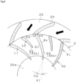
- FIG. 5 illustrates an enlarged cross-sectional view of the stay vane and the runner in a plane orthogonal to the rotation axis.
- the runner vane 33a which is at least one of the plurality of runner vanes, is a long blade and reaches the opening 32a.
- the runner vane 33a has a pressure surface Sp that receives pressure in an inflow direction from water flowing into the runner 3 through the fixed flow path 22, and a negative pressure surface Sn that receives pressure lower than the pressure surface Sp on a back side surface of the pressure surface Sp.
- an outlet angle ⁇ 1 formed by a tangent at a tip portion on the outlet side of the pressure surface Sp and a line segment connecting the rotation axis O and the tip portion on the outlet side of the pressure surface Sp is 0° or more and less than 20°.
- the outlet angle ⁇ 1 of at least one runner vane is 0° or more and less than 20°, a vortex is less likely to be generated in the central portion of the runner, and water is smoothly discharged without resistance.
- the outlet angle ⁇ 1 of at least one long-blade runner vane is 0° or more and less than 20°, a vortex is less likely to be generated in the central portion of the runner, and water is smoothly discharged without resistance. Accordingly, in the hydraulic machine of the present invention, water smoothly flows in the flow path, and power generation efficiency is excellent.
- the outlet angle ⁇ 1 is not limited to 0° or more and less than 20°, and can be freely set. From the viewpoint of reducing generation of a vortex, the outlet angle ⁇ 1 is preferably 0° or more and less than 15°, and more preferably 0° or more and less than 10°.
- the hydraulic machine of the present invention is used in a small hydraulic power generation apparatus, for example, used in a hydraulic power generation apparatus under the conditions of a low flow rate of less than 100 Us and a low effective elevation difference of 200 m or less, or used in a hydraulic power generation apparatus having a power generation output of 10,000 kW or less, the specific speed is small, so that a vortex is less likely to be generated at the central portion of the runner, and water is smoothly discharged without resistance. Accordingly, water smoothly flows in the flow path, and power generation efficiency becomes further excellent.
- An angle of a tip portion on an outlet side of a runner vane used in a conventional large water turbine is larger than 20°, and there are many structures in which water is discharged from the runner in a circle. When such a structure is used in the small hydraulic power generation apparatus as described above, there is a possibility that a vortex is generated in the central portion of the runner and it is difficult to smoothly discharge water.
- the runner illustrated in FIG. 5 is a splitter runner.
- the plurality of runner vanes included in the splitter runner includes a first runner vane 33a and a second runner vane 33b having a shorter blade length than the first runner vane 33a.
- the first runner vane 33a which is a long blade and the second runner vane 33b which is a short blade are alternately provided.
- a blade length L2 of the second runner vane is about 60% of a blade length L1 of the first runner vane.
- the blade length L1 of the first runner vane only needs to be longer than the blade length L2 of the second runner vane.
- the blade length L2 of the second runner vane is preferably 40% to 80%, and more preferably 50% to 70%, with respect to the blade length L1 of the first runner vane. Since the blade lengths of the first runner vane and the second runner vane have the above relationship, the runner easily obtains the rotational force from the water and does not inhibit the discharge flow of the water, and the power generation efficiency of the hydraulic machine is excellent.
- the runner When the runner is simply a splitter runner in which the blade length L2 of the second runner vane is 40% to 80% of the blade length L1 of the first runner vane, the rotational force is improved, but the runner flow path is narrowed.
- the runner When the runner is a splitter runner and the outlet angle ⁇ 1 of at least one long-blade runner vane of the plurality of runner vanes is brought close to 0° to smooth the discharge flow, the power generation efficiency is particularly improved.
- a curvature radius R1 on the inlet side (hereinafter referred to as “inlet-side curvature radius”) of the pressure surface Sp of the runner vane 33 and a curvature radius R2 on the outlet side (hereinafter referred to as “outlet-side curvature radius”) of the pressure surface Sp can be freely set, and for example, the inlet-side curvature radius R1 can be set to 50 mm to 80 mm, and the outlet-side curvature radius R2 can be set to 40 mm to 70 mm.
- the inlet-side curvature radius R1 is larger than the outlet-side curvature radius R2, the inlet-side curvature radius R1 is 50 mm to 80 mm, and the outlet-side curvature radius R2 is 40 mm to 70 mm.
- the inlet side is a portion of the runner vane corresponding to 1/2 of the blade length on the runner outer peripheral side
- the outlet side is a portion of the runner vane corresponding to 1/2 of the blade length on the runner inner peripheral side (opening side).
- the angle ⁇ 2 formed by the tangent of the camber line tip on the outlet side of the stay vane 25 and the tangent of the camber line tip on the inlet side of the runner vane 33 can be freely set to, for example, 85° to 120°.
- the runner vane herein is not limited to a long blade.
- the angle ⁇ 2 is preferably 90° to 96°, and more preferably 92° to 96°. When the angle ⁇ 2 is within the above range, this contributes to improvement of power generation efficiency.
- the angle ⁇ 2 is preferably 90° to 120°, and more preferably 100° to 120° from the viewpoint of smoothing the flow.
- a curvature radius R3 of the negative pressure surface Sn at the inlet-side end of the runner vane 33 can be freely set, and can be, for example, 1 mm to 10 mm.
- the average thickness of the runner vane 33 on the inlet side can be freely set, and can be, for example, 4 mm to 15 mm.
- the curvature radius R3 is preferably 2 mm to 8 mm from the viewpoint of smoothing the flow on the negative pressure surface side, suppressing the generation of cavitation, addressing a high elevation difference, and the like.
- the curvature radius R3 of the runner vane is within the above range, it leads to suppression of variation in the rotational force and vibration of the runner, and power generation efficiency is improved.
- pressure Simultaneous pressure
- simultaneously generated in the stay vane and the runner vane is less likely to be applied, which contributes to suppression of vibration and noise and to improvement of power generation efficiency.
- FIG. 6 is a cross-sectional view of the casing included in the hydraulic machine of the present invention taken along a plane orthogonal to the runner rotation axis.
- the present cross-sectional view is a cross-sectional view taken along line A-A' in FIG. 2 .
- the space between the terminal end portion 24 of the main flow path 21 and the inflow portion 23 is partitioned by a first stay vane 28 extending from the inflow portion 23, the terminal end portion 24 and the inflow portion 23 do not communicate with each other, and the respective portions are not directly connected (hereinafter also referred to as "non-penetrating structure").
- the main flow path has the non-penetrating structure as described above, all the waterflowing into the casing flows toward the runner through the fixed flow path. Therefore, as compared with the case of a structure in which there is no partition between the terminal end portion and the inflow portion and they are directly connected (hereinafter also referred to as "penetrating structure"), the flow around the main flow path does not flow from the terminal end portion to the inflow portion again, so that the flow velocity of water in the flow path becomes uniform and energy loss due to merging does not occur. As a result, the hydraulic machine of the present invention is excellent in power generation efficiency.
- the hydraulic machine of the present invention is preferably used in a small hydraulic power generation apparatus under the conditions of a low flow rate of less than 100 Us and a low effective elevation difference of 200 m or less, or used in a hydraulic power generation apparatus having a power generation output of 10,000 kW or less. In this case, the flow of water is less likely to stagnate and the resistance becomes low, and the power generation efficiency is further excellent.
- the inner diameter of the main flow path may be continuously decreased at a predetermined change rate toward the center of the spiral, or the inner diameter may be gradually decreased by connecting the flow paths having a constant inner diameter such that the inner diameter stepwisely becomes smaller.
- a continuous diameter reduction of the inner diameter and a stepwise diameter reduction of the inner diameter may be combined.
- the main flow path may have a diameter decreased with a diameter reduction ratio changing stepwise, the diameter reduction ratio being a ratio of the inner diameter on an outlet side to the inner diameter on an inlet side in a predetermined angle range.
- the diameter reduction ratio may increase or decrease in the first half portion, the intermediate portion, and the second half portion of the main flow path.
- the diameter reduction ratio can be set, for example, such that the inner diameter decreases by 5% to 35% every 45° or 90° advance toward the center of the spiral.
- the inner diameter d90 at a position of 90° from the downstream end portion of the inflow portion 23 toward the center of the spiral is smaller than the inner diameter d0 of the downstream end portion of the inflow portion 23 by about 20 to 30%.
- an inner diameter d180 at a position of 180° from the downstream end of the inflow portion 23 toward the center of the spiral is smaller than the inner diameter d90 by slightly more than 30%.
- an inner diameter d270 at a position of 270° from the downstream end of the inflow portion 23 toward the center of the spiral is smaller than the inner diameter d180 by slightly more than 20 to 30%.
- the diameter reduction ratio of the intermediate portion of the main flow path may be larger than the diameter reduction ratios of the first half portion and the second half portion.
- the flow velocity from the inflow portion to the terminal end portion of the main flow path is made uniform over the entire circumference.
- the flow of water is made smooth, so that the generation of vibration is reduced and the power generation efficiency is more excellent.
- FIG. 7 illustrates a cross-sectional view of an exemplary casing included in the hydraulic machine of the present invention, taken along a plane orthogonal to a runner rotation axis of the casing in which a stay vane interval changes.
- the interval between the plurality of stay vanes 25 adjacent to each other sequentially decreases toward the center of the spiral from the inflow portion 23 of the main flow path 21 to the terminal end portion 24.
- the flow path widths of the plurality of fixed flow paths connected to the first half portion of the main flow path may be constant, and the flow path widths of the plurality of fixed flow paths connected to the main flow path from the intermediate portion to the second half portion may sequentially decrease. The same applies to a case described later where the flow path width sequentially increases toward the center of the spiral of the main flow path.
- FIG. 8 illustrates an enlarged cross-sectional view of a stay vane portion of the casing illustrated in FIG. 7 .
- the flow path width which is the length of an arc on the inner peripheral side of the fixed flow path 22 disposed between the adjacent stay vanes 25 among the plurality of stay vanes 25, sequentially decreases toward the center of the spiral of the main flow path.
- the reduction rate D1 of the flow path width is expressed by the following formula (1).
- D 1 ⁇ 2 L ⁇ YN ⁇ SN /YN N ⁇ 1
- the flow velocity tends to increase due to the effect of reducing the inner diameter, but this makes it difficult for water to flow to the stay vane side, and the flow velocity in the fixed flow path connected to the second half portion of the main flow path may become slow in some cases.
- the flow path width of the fixed flow path connected to the second half portion of the main flow path is narrowed and the flow velocity is increased.
- the flow velocity of the water flowing into the runner from the fixed flow path is made uniform, and the runner is loaded with a uniform rotational force over the entire circumference, so that the generation of vibration is reduced, and the power generation efficiency is further excellent.
- the casing included in the hydraulic machine of the present invention is not limited to the above-described casing in which the flow path width, which is the length of the arc on the inner peripheral side of the fixed flow path disposed between the adjacent stay vanes among the plurality of stay vanes, sequentially decreases toward the center of the spiral of the main flow path.
- the flow path width may sequentially increase, for example, toward the center of the spiral of the main flow path.
- the increase rate D2 of the flow path width is expressed by the following formula (2).
- D 2 2 L ⁇ YN ⁇ SN /YN N ⁇ 1
- Sequentially changing the interval (flow path width) between the plurality of stay vanes and reducing the inner diameter of the main flow path toward the center of the spiral of the main flow path are methods of uniformizing the flow velocity over the entire circumference.
- uniformization of the flow velocity over the entire circumference is more easily achieved.
- the casing 2 includes 13 stay vanes 25.
- the number of stay vanes can be freely set, and can be, for example, 5 to 30. From the viewpoint of reducing simultaneous pressure application to the stay vanes and the runner vanes, the number of runner vanes is larger than the number of stay vanes, and the number of stay vanes is preferably 5 to 20, and more preferably 8 to 15. When the number of stay vanes is within the above range, simultaneous pressure is less likely to be applied to the stay vanes and the runner vanes, whereby vibration and noise are suppressed, and power generation efficiency is improved.
- the number of stay vanes, the number of runner vanes, the length of the arc on the inner peripheral side of the stay vane, and the length of the arc on the outer peripheral side of the runner vane are preferably set to satisfy the following formula (3).
- T is specifically a length of an arc on the outer periphery of the runner formed when tangents at the tip portions of the pressure surface and the negative pressure surface on the inlet side of the runner vane are extended in the outer peripheral direction.
- the x-th stay vane and the runner vane do not overlap each other, and the positional relationship is the same as or more than the angle corresponding to the sum of the arc length S on the inner peripheral side of the stay vane and the arc length T on the outer peripheral side of the runner vane. Accordingly, simultaneous pressure is less likely to be applied to the stay vanes and the runner vanes, whereby vibration and noise are suppressed, and power generation efficiency is improved.
- FIG. 9 illustrates an enlarged sectional view of a sliding contact portion between the casing and the runner taken along the runner rotation axis.
- the runner 3 and the casing 2 have respective sliding contact portions that slidably contact with each other.
- the sliding contact portion of the runner 3 is a protruded portion 32c having an annular shape that is formed on a concentric circle about the rotation axis on the surface of the casing on the side where the runner 3 faces the runner disposing portion 27 and protrudes in a discharge direction (a direction of a black arrow) that is a direction in which water is discharged from the runner 3.
- the sliding contact portion of the casing 2 is a groove portion 27a having an annular shape that is formed on a concentric circle about the axial center of the main shaft in the runner disposing portion 27 in which the runner 3 is disposed and is recessed in the discharge direction.
- the protruded portion 32c is fitted to the groove portion 27a with a slight gap.
- the gap between the protruded portion and the groove portion can be freely set, and can be, for example, 0.5 mm to 5 mm. From the viewpoint of slidability of the runner with respect to the casing and reduction of the amount of water leaking from the gap, the gap between the protruded portion and the groove portion is preferably 1 mm to 3 mm.
- the gap between the protruded portion and the groove portion is within the above range, the amount of water that flows between the casing and the runner and is discharged without applying a rotational force to the runner can be reduced, and the amount of water that flows between the runner vanes can be increased. Accordingly, since the energy of the flowing water can be efficiently used for the rotation of the runner, the hydraulic machine of the present invention is further excellent in power generation efficiency.
- the hydraulic machine of the present invention may be provided with a detection system such as an acceleration sensor that measures acceleration acting on the hydraulic machine, a current/voltage sensor capable of measuring current and voltage, a camera capable of capturing an appearance photograph or an appearance moving image, and a human sensor capable of detecting when a person or an animal approaches.
- a detection system such as an acceleration sensor that measures acceleration acting on the hydraulic machine, a current/voltage sensor capable of measuring current and voltage, a camera capable of capturing an appearance photograph or an appearance moving image, and a human sensor capable of detecting when a person or an animal approaches.
- the acceleration sensor can be attached to the vicinity of the rotation axis of the hydraulic machine to detect the movement values of the X, Y, and Z axes, and when the movement values exceed a set threshold, the acceleration sensor can notify the administrator by e-mail or the like.
- the current/voltage sensor can detect a current value and a voltage value by attaching a clamp sensor to a three-phase AC wiring from a generator, and notify an administrator by e-mail or the like when the current value and the voltage value exceed a set threshold.
- the moving values of the X, Y, and Z axes, the current value, and the voltage value can be confirmed by a graph in real time on the WEB.
- the data acquisition interval is, for example, every 1 second, and may be acquired every 0.5 seconds to every day depending on the installation environment.
- the camera can be installed around the hydraulic machine, and the camera can be activated at a fixed time to take an appearance photograph or an appearance moving image to notify the administrator by e-mail or the like whether there is a trouble such as damage, impact, or disaster.
- the administrator can quickly respond to the occurrence of an abnormality such as a disaster or mixing of foreign matter into the hydraulic machine, power generation can be continuously performed.
- the various detection systems described above may include a prediction system that performs data analysis on the basis of acquired information and performs future abnormality occurrence prediction.
- the prediction system notifies the administrator of the predicted information, and the administrator handles the information, thereby avoiding failure of the hydraulic machine.
- the hydraulic machine of the present invention allows water to smoothly flow in a flow path and has excellent power generation efficiency.
- the flow velocity of water in the flow path is uniform, it can be widely used for power generation applications using flowing water from water channels, factory effluents, household effluents, water purification plants, and the like.
Landscapes
- Engineering & Computer Science (AREA)
- Chemical & Material Sciences (AREA)
- Combustion & Propulsion (AREA)
- Mechanical Engineering (AREA)
- General Engineering & Computer Science (AREA)
- Hydraulic Turbines (AREA)
Applications Claiming Priority (3)
| Application Number | Priority Date | Filing Date | Title |
|---|---|---|---|
| JP2021082839A JP7506411B2 (ja) | 2021-05-14 | 2021-05-14 | 水力機械 |
| JP2021082838A JP7506410B2 (ja) | 2021-05-14 | 2021-05-14 | 水力機械 |
| PCT/JP2022/016538 WO2022239571A1 (ja) | 2021-05-14 | 2022-03-31 | 水力機械 |
Publications (2)
| Publication Number | Publication Date |
|---|---|
| EP4339447A1 true EP4339447A1 (de) | 2024-03-20 |
| EP4339447A4 EP4339447A4 (de) | 2025-10-22 |
Family
ID=84028266
Family Applications (1)
| Application Number | Title | Priority Date | Filing Date |
|---|---|---|---|
| EP22807275.7A Pending EP4339447A4 (de) | 2021-05-14 | 2022-03-31 | Hydraulische maschine |
Country Status (3)
| Country | Link |
|---|---|
| US (1) | US12378939B2 (de) |
| EP (1) | EP4339447A4 (de) |
| WO (1) | WO2022239571A1 (de) |
Family Cites Families (18)
| Publication number | Priority date | Publication date | Assignee | Title |
|---|---|---|---|---|
| US4566166A (en) * | 1984-10-03 | 1986-01-28 | Allis-Chalmers Corporation | Method for manufacturing a stay ring bearing stationary guide vanes for a nongated turbine |
| JPS61101680A (ja) * | 1984-10-22 | 1986-05-20 | Toshiba Corp | フランシス形ランナ |
| JP2000297736A (ja) | 1999-04-14 | 2000-10-24 | Toshiba Corp | 水力機械のシール装置 |
| JP2003013835A (ja) | 2001-06-28 | 2003-01-15 | Toshiba Corp | 水力機械およびその運転制御方法 |
| FR2844560B1 (fr) * | 2002-09-13 | 2006-01-27 | Alstom Switzerland Ltd | Roue de type francis et machine hydraulique equipee d'une telle roue |
| CN1231664C (zh) * | 2003-06-11 | 2005-12-14 | 高德瑜 | 水力涡轮机系统 |
| JP2007023844A (ja) * | 2005-07-14 | 2007-02-01 | Mitsubishi Heavy Ind Ltd | 水力機械 |
| JP4751165B2 (ja) * | 2005-10-12 | 2011-08-17 | 株式会社東芝 | フランシス形ポンプ水車 |
| JP5118513B2 (ja) * | 2008-03-03 | 2013-01-16 | 日立三菱水力株式会社 | 隔壁構造及び水力機械 |
| JP5117349B2 (ja) * | 2008-10-03 | 2013-01-16 | 株式会社東芝 | 水力機械 |
| JP2010101265A (ja) | 2008-10-24 | 2010-05-06 | Toshiba Corp | フランシス型水力機械のランナおよびフランシス型水力機械 |
| JP2011149341A (ja) | 2010-01-22 | 2011-08-04 | Kenhiko Nonaka | 多機能傾斜型発電装置 |
| JP2013072304A (ja) | 2011-09-27 | 2013-04-22 | Toshiba Corp | 水力機械 |
| JP6605018B2 (ja) * | 2014-07-23 | 2019-11-13 | アンドリッツ ハイドロ リミテッド | 短いブレード及び短いバンドを備えるフランシスタービン |
| CN107725251A (zh) * | 2017-10-10 | 2018-02-23 | 河海大学 | 应用于低水头抽水蓄能电站的可逆式水泵水轮机转轮 |
| US10895165B2 (en) * | 2018-07-31 | 2021-01-19 | Dong Hse Engineering Co., Ltd. | Double-flow type volute casing having structure for changing direction of flow in turbine inlet |
| CN111720252A (zh) * | 2020-05-11 | 2020-09-29 | 华北水利水电大学 | 一种混流式与轴流式转轮组合的两级水轮机 |
| JP2025101680A (ja) * | 2023-12-25 | 2025-07-07 | 伊藤超短波株式会社 | 電流刺激装置 |
-
2022
- 2022-03-31 WO PCT/JP2022/016538 patent/WO2022239571A1/ja not_active Ceased
- 2022-03-31 US US18/290,449 patent/US12378939B2/en active Active
- 2022-03-31 EP EP22807275.7A patent/EP4339447A4/de active Pending
Also Published As
| Publication number | Publication date |
|---|---|
| US12378939B2 (en) | 2025-08-05 |
| WO2022239571A1 (ja) | 2022-11-17 |
| EP4339447A4 (de) | 2025-10-22 |
| US20240247633A1 (en) | 2024-07-25 |
Similar Documents
| Publication | Publication Date | Title |
|---|---|---|
| RU2444642C2 (ru) | Гидроэлектрическая турбина для использования в двунаправленном приливно-отливном течении | |
| JP5809126B2 (ja) | マイクロ水力発電機 | |
| CN104066971B (zh) | 水力机械 | |
| RU2391554C1 (ru) | Низконапорная ортогональная турбина | |
| EP4339447A1 (de) | Hydraulische maschine | |
| JP7506411B2 (ja) | 水力機械 | |
| EP2326829B1 (de) | Mit einem gitter versehenes wasserkraftwerk und betriebsverfahren dafür | |
| KR101959887B1 (ko) | 노 형상을 갖는 블레이드를 구비한 관로형 소수력 발전장치 | |
| JP7506410B2 (ja) | 水力機械 | |
| JP5442673B2 (ja) | 発電装置 | |
| KR101097771B1 (ko) | 소형수력발전기 | |
| JP4768361B2 (ja) | フランシス形ランナ及び水力機械 | |
| CN213450853U (zh) | 一种整流器以及大流量低能耗轴流式排灌装置 | |
| JP2008014202A (ja) | 水力発電装置 | |
| KR101981553B1 (ko) | 유속을 이용한 동력을 발생시키는 회전스크류 구조체 | |
| KR20100104967A (ko) | 가변익 터빈 | |
| JP2011094487A (ja) | 流体エネルギ回収装置 | |
| EP3495654A1 (de) | Leitschaufel für eine axiale kaplanturbine | |
| KR20150024879A (ko) | 날개와 케이싱이 일체화된 발전용 터빈 및 이를 이용한 발전방법 | |
| JPH08338354A (ja) | 低流速用水車装置と低流速用水車装置の導水方向設定方 法 | |
| JP6935658B2 (ja) | 流体機械の製造方法 | |
| CN107762713A (zh) | 一种适用于大流量的多功能减压阀 | |
| CN114517762A (zh) | 一种集流式海流能水轮机装置 | |
| JP4856283B1 (ja) | 水力回転装置 | |
| KR20170106630A (ko) | 날개와 원통이 일체화된 발전 터빈 및 이를 이용한 발전방법 |
Legal Events
| Date | Code | Title | Description |
|---|---|---|---|
| STAA | Information on the status of an ep patent application or granted ep patent |
Free format text: STATUS: THE INTERNATIONAL PUBLICATION HAS BEEN MADE |
|
| PUAI | Public reference made under article 153(3) epc to a published international application that has entered the european phase |
Free format text: ORIGINAL CODE: 0009012 |
|
| STAA | Information on the status of an ep patent application or granted ep patent |
Free format text: STATUS: REQUEST FOR EXAMINATION WAS MADE |
|
| 17P | Request for examination filed |
Effective date: 20231101 |
|
| AK | Designated contracting states |
Kind code of ref document: A1 Designated state(s): AL AT BE BG CH CY CZ DE DK EE ES FI FR GB GR HR HU IE IS IT LI LT LU LV MC MK MT NL NO PL PT RO RS SE SI SK SM TR |
|
| DAV | Request for validation of the european patent (deleted) | ||
| DAX | Request for extension of the european patent (deleted) | ||
| A4 | Supplementary search report drawn up and despatched |
Effective date: 20250924 |
|
| RIC1 | Information provided on ipc code assigned before grant |
Ipc: F03B 3/02 20060101AFI20250918BHEP Ipc: F03B 3/18 20060101ALI20250918BHEP Ipc: F03B 3/12 20060101ALI20250918BHEP |