EP4339080A1 - Tunnelroboter - Google Patents
Tunnelroboter Download PDFInfo
- Publication number
- EP4339080A1 EP4339080A1 EP23197978.2A EP23197978A EP4339080A1 EP 4339080 A1 EP4339080 A1 EP 4339080A1 EP 23197978 A EP23197978 A EP 23197978A EP 4339080 A1 EP4339080 A1 EP 4339080A1
- Authority
- EP
- European Patent Office
- Prior art keywords
- module
- tunnel
- robot
- walking
- robot body
- Prior art date
- Legal status (The legal status is an assumption and is not a legal conclusion. Google has not performed a legal analysis and makes no representation as to the accuracy of the status listed.)
- Granted
Links
Images


Classifications
-
- B—PERFORMING OPERATIONS; TRANSPORTING
- B62—LAND VEHICLES FOR TRAVELLING OTHERWISE THAN ON RAILS
- B62D—MOTOR VEHICLES; TRAILERS
- B62D57/00—Vehicles characterised by having other propulsion or other ground- engaging means than wheels or endless track, alone or in addition to wheels or endless track
- B62D57/02—Vehicles characterised by having other propulsion or other ground- engaging means than wheels or endless track, alone or in addition to wheels or endless track with ground-engaging propulsion means, e.g. walking members
- B62D57/024—Vehicles characterised by having other propulsion or other ground- engaging means than wheels or endless track, alone or in addition to wheels or endless track with ground-engaging propulsion means, e.g. walking members specially adapted for moving on inclined or vertical surfaces
-
- B—PERFORMING OPERATIONS; TRANSPORTING
- B62—LAND VEHICLES FOR TRAVELLING OTHERWISE THAN ON RAILS
- B62D—MOTOR VEHICLES; TRAILERS
- B62D63/00—Motor vehicles or trailers not otherwise provided for
- B62D63/02—Motor vehicles
- B62D63/04—Component parts or accessories
-
- B—PERFORMING OPERATIONS; TRANSPORTING
- B64—AIRCRAFT; AVIATION; COSMONAUTICS
- B64C—AEROPLANES; HELICOPTERS
- B64C27/00—Rotorcraft; Rotors peculiar thereto
- B64C27/32—Rotors
-
- B—PERFORMING OPERATIONS; TRANSPORTING
- B64—AIRCRAFT; AVIATION; COSMONAUTICS
- B64U—UNMANNED AERIAL VEHICLES [UAV]; EQUIPMENT THEREFOR
- B64U10/00—Type of UAV
- B64U10/10—Rotorcrafts
-
- B—PERFORMING OPERATIONS; TRANSPORTING
- B64—AIRCRAFT; AVIATION; COSMONAUTICS
- B64U—UNMANNED AERIAL VEHICLES [UAV]; EQUIPMENT THEREFOR
- B64U10/00—Type of UAV
- B64U10/70—Convertible aircraft, e.g. convertible into land vehicles
-
- B—PERFORMING OPERATIONS; TRANSPORTING
- B64—AIRCRAFT; AVIATION; COSMONAUTICS
- B64U—UNMANNED AERIAL VEHICLES [UAV]; EQUIPMENT THEREFOR
- B64U30/00—Means for producing lift; Empennages; Arrangements thereof
- B64U30/20—Rotors; Rotor supports
- B64U30/26—Ducted or shrouded rotors
-
- B—PERFORMING OPERATIONS; TRANSPORTING
- B64—AIRCRAFT; AVIATION; COSMONAUTICS
- B64U—UNMANNED AERIAL VEHICLES [UAV]; EQUIPMENT THEREFOR
- B64U30/00—Means for producing lift; Empennages; Arrangements thereof
- B64U30/20—Rotors; Rotor supports
- B64U30/29—Constructional aspects of rotors or rotor supports; Arrangements thereof
-
- E—FIXED CONSTRUCTIONS
- E21—EARTH OR ROCK DRILLING; MINING
- E21F—SAFETY DEVICES, TRANSPORT, FILLING-UP, RESCUE, VENTILATION, OR DRAINING IN OR OF MINES OR TUNNELS
- E21F17/00—Methods or devices for use in mines or tunnels, not covered elsewhere
-
- E—FIXED CONSTRUCTIONS
- E21—EARTH OR ROCK DRILLING; MINING
- E21F—SAFETY DEVICES, TRANSPORT, FILLING-UP, RESCUE, VENTILATION, OR DRAINING IN OR OF MINES OR TUNNELS
- E21F17/00—Methods or devices for use in mines or tunnels, not covered elsewhere
- E21F17/18—Special adaptations of signalling or alarm devices
-
- G—PHYSICS
- G01—MEASURING; TESTING
- G01M—TESTING STATIC OR DYNAMIC BALANCE OF MACHINES OR STRUCTURES; TESTING OF STRUCTURES OR APPARATUS, NOT OTHERWISE PROVIDED FOR
- G01M3/00—Investigating fluid-tightness of structures
- G01M3/005—Investigating fluid-tightness of structures using pigs or moles
-
- B—PERFORMING OPERATIONS; TRANSPORTING
- B64—AIRCRAFT; AVIATION; COSMONAUTICS
- B64U—UNMANNED AERIAL VEHICLES [UAV]; EQUIPMENT THEREFOR
- B64U2101/00—UAVs specially adapted for particular uses or applications
- B64U2101/25—UAVs specially adapted for particular uses or applications for manufacturing or servicing
- B64U2101/26—UAVs specially adapted for particular uses or applications for manufacturing or servicing for manufacturing, inspections or repairs
-
- B—PERFORMING OPERATIONS; TRANSPORTING
- B64—AIRCRAFT; AVIATION; COSMONAUTICS
- B64U—UNMANNED AERIAL VEHICLES [UAV]; EQUIPMENT THEREFOR
- B64U2101/00—UAVs specially adapted for particular uses or applications
- B64U2101/70—UAVs specially adapted for particular uses or applications for use inside enclosed spaces, e.g. in buildings or in vehicles
Definitions
- the disclosure relates to the technical field of robots, in particular to a tunnel operation robot.
- the tunnel operation robot includes a power supply and a rotating fan, and the power supply provides power to the rotation fan to make the rotation fan work, thereby keeping the tunnel operation robot suspended.
- the requirements for tunnel operations become more and more stringent, the operating devices on tunnel operation robots are becoming more and more complex and heavier.
- the current common practice is to increase the radius of the rotating fan, and increasing the radius of the rotating fan usually increases the size of the tunnel operation robot in different directions. Furthermore, due to the influence of the included angle between the bottom of the tunnel and the ground, and the curvature of the tunnel itself, it is prone to encountering work blind spots due to interference issues in the direction contained within the cross section of the tunnel.
- the disclosure aims to solve at least one of the technical problems in the existing technology. For this reason, the disclosure proposes a tunnel operation robot, which has a relatively large load capacity, and is not prone to encountering work blind spot due to interference issue, and is more convenient to control.
- the tunnel operation robot includes a robot body, a walking module, a fixed wing module and a plurality of rotatable wing modules. Both sides of the robot body are provided with protruding cantilever parts, and the cantilever parts on both sides are collinearly arranged.
- the walking module is arranged on the robot body, and is configured to drive the robot body to walk and steer on a tunnel wall surface.
- the fixed wing module includes a fixed fan and is arranged on the robot body, and is configured to provide a pressure for the walking module to be pressed and attached to the tunnel wall surface.
- the plurality of rotatable wing module are respectively arranged on the cantilever parts on both sides of the robot body, and include a rotatably arranged rotating fan and a wind direction adjustment driver.
- Each rotating fan has a rotation axis parallel to an extension direction of the cantilever parts and an air outlet direction perpendicular to the extension direction of the cantilever parts, and the wind direction adjustment driver is connected to the rotating fan, and is configured to maintain the air outlet direction of the rotating fan downward to generate a thrust capable of balancing gravity.
- the tunnel operation robot according to the embodiment of the disclosure has at least the following beneficial effects.
- the walking module in the tunnel operation robot can be attached to and contact with the tunnel wall surface with a certain pressure.
- the rotatable wing modules By arranging the rotatable wing modules, and enabling the rotating fans in the rotatable wing modules to keep the wind outlet direction downward under the drive of the wind direction adjustment driver, so that the rotatable wing modules can generate a thrust for balancing the gravity, and further by means of the walking module, the walking and steering of the tunnel operation robot on the wall surface can be realized.
- the tunnel operation robot can use the rotatable wing modules, the fixed wing module and the walking module to respectively realize suspension, wall pressing and attaching, and walking, the control process is simpler and easier to operate. Meanwhile, since there are multiple rotatable wing modules for generating an upward thrust, it can generate a more powerful lifting force to balance the gravity, so that the tunnel operation robot can bear greater gravity to carry an operation module with more comprehensive functions and larger weight.
- the rotatable wing modules are all connected to the cantilever parts collinearly arranged on both sides of the robot body, the plurality of rotatable wing modules arranged to enhance the lifting force are arranged along the same direction, so they only affect the size of the tunnel operation robot in the extension direction of the cantilever part, and it is not prone to encountering work blind spots due to interference issues in the direction contained within the cross section of the tunnel.
- the rotation axis of each rotating fan is located on the same straight line passing through a center of gravity of the tunnel operation robot.
- the rotatable wing modules on the cantilever parts on both sides of the robot body are arranged symmetrically.
- the rotatable wing modules are detachably connected to the cantilever parts.
- the rotatable wing module further includes a connecting frame and a rotating bracket, the rotating fan is arranged on the rotating bracket, and the wind direction adjustment driver is connected to the connecting frame and the rotating bracket, and is capable of driving the rotating bracket to rotate relative to the connecting frame, and the connecting frame is detachably connected to a corresponding one of the cantilever parts.
- the tunnel operation robot further includes a control module
- the rotatable wing module further includes a thrust detection device
- the thrust detection device is arranged between the rotating bracket and the rotating fan, and configured to detect a magnitude of the thrust transmitted from the rotating fan to the rotating bracket, and both the thrust detection device and the rotating fan are electrically connected to the control module.
- the tunnel operation robot further includes a mounting rod, a middle part of the mounting rod passes through the robot body, and both ends of the mounting rod protrude from the robot body to form the cantilever parts.
- a pressure detection device is provided between the robot body and the walking module, and the pressure detection device is configured to detect a pressure transmitted from the robot body to the walking module.
- the walking module includes a frame body, a walking assembly and a driving assembly, the walking assembly is arranged on the frame body and configured for walking and steering, the driving assembly is arranged on the frame body and connected to the walking assembly for driving, the frame body is detachably connected to the robot body, and the pressure detection device is arranged between the frame body and the robot body.
- a detection module is arranged inside the robot body, the detection module is configured to detect a tunnel, the frame body is arranged in a framework-model manner, a detection port is formed in a middle of the frame body, the detection module penetrates through the detection port, and a detection end of the detection module protrudes from the frame body.
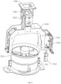
- Robot body 100 cantilever part 110; detection module 200; walking module 300; second pressure sensor 310; frame body 320; detection port 321; walking assembly 330; driving assembly 340; fixed wing module 400; fixed fan 410; fixing bracket 420; rotatable wing module 500; rotating fan 510; ear plate 511; connecting piece 512; wind direction adjustment driver 520; connecting frame 530; first connection part 531; second connection part 532; first connection through hole 533; rotating bracket 540; abutting part 541; connecting plate 550; second connection through hole 551; thrust detection device 560.
- orientation or positional relationships indicated by “up”, “down”, “front”, “back”, “left”, “right”, etc. are based on the orientation or positional relationships shown in the accompanying drawings, and are to facilitate the description of the present disclosure and simplify the description only, rather than indicating or implying that the device or element referred to must have a specific orientation or be constructed and operated in a specific orientation, and therefore cannot be construed as limiting the present disclosure.
- a tunnel operation robot includes a robot body 100, a walking module 300, a fixed wing module 400 and a plurality of rotatable wing modules 500.
- Both sides of the robot body 100 are provided with protruding cantilever parts 110, and the cantilever parts 110 on both sides are collinearly arranged.
- the walking module 300 is arranged on the robot body 100, and is configured to drive the robot body 100 to walk and turn on a tunnel wall surface.
- the fixed wing module 400 is arranged on the robot body 100, and includes a fixed fan 410, and is configured to provide pressure for the walking module 300 to be pressed against the tunnel wall surface.
- the plurality of rotatable wing modules 500 are respectively arranged on the cantilever parts 110 on both sides of the robot body 100, and each include a rotatably arranged rotating fan 510 and a wind direction adjustment driver 520.
- Each rotating fan 510 has a rotation axis parallel to an extension direction of the cantilever part 110, and a wind outlet direction perpendicular to the extension direction of the cantilever part 110.
- the wind direction adjustment driver 520 is connected to the rotating fan 510 and is configured to keep the wind outlet direction of the rotary fan 510 downward to generate a thrust for balancing the gravity.
- the tunnel operation robot may further be provided with an operation module.
- the operation module is a detection module 200
- the detection module 200 is arranged inside the robot body 100.
- a detection end of the detection module 200 is exposed from the robot body 100, and the detection end is located on a side of the robot body 100 where the walking module 300 is disposed.
- the operation module can also be configured according to different types of operations required, and can also include multiple operation modules for completing various types of operations.
- a vacuum cleaner, an air duct, and a cleaning roller brush similar to the sweeping robot can also be arranged inside the robot body 100, and the surrounding sides of the cleaning roller brush are exposed from the robot body 100, so as to be able to contact the tunnel wall surface to be cleaned.
- a camera device can also be arranged inside the robot body 100, and the camera of the camera device is exposed from the robot body 100, so as to be able to photograph the tunnel wall surface to be photographed.
- the detection module 200 and the camera device can also be installed inside the robot body 100 at the same time.
- the detection module 200 can also be selected according to the category of items detected on the wall surface of the tunnel, for example, it can be a nuclear magnetic resonance detection device, an electromagnetic wave detection device and an ultrasonic detection device, etc., and the type of the detection module 200 is not specifically limited herein.
- the tunnel operation robot when the wall surface of the tunnel is detected by the tunnel operation robot according to the embodiment of the disclosure, firstly, the side of the tunnel operation robot equipped with the walking module 300 is abutted against the wall surface of the tunnel by manually grabbing the tunnel operation robot (at this time, the cantilever part 110 of the tunnel operation robot is close to a horizontal state, and the extension direction of the cantilever part 110 is roughly close to the extension direction of the tunnel, that is, the length direction of the tunnel). Then the tunnel operation robot is be started to work in the tunnel. After the tunnel operation robot is started, both the fixed-wing module 400 and the rotatable wing module 500 start to work.
- the attitude detection mechanism such as gyroscope installed inside the robot body 100 will automatically detect the attitude state of the tunnel operation robot.
- the walking module 300 works and performs quick adjustments such as walking and steering, so that the cantilever part 110 is in a horizontal state, that is, the leveling of the cantilever part 110 is completed (since the rotation axis of the rotating fan 510 is parallel to the extension direction of the cantilever part 110, when the cantilever part 110 is adjusted to a horizontal state, it is convenient to adjust the rotating fan 510 to enable the air outlet direction to be vertically downward).
- the rotating fan 510 in the rotatable wing module 500 is also driven by the wind direction adjustment driver 520 to complete adjustment of the wind outlet direction to be vertically downward. Therefore, attachment to the wall and suspension can be realized by means of the fixed wing module 400 and the rotatable wing module 500.
- the walking module 300 drives the entire tunnel operation robot to walk on the wall surface of the tunnel, so that the tunnel operation robot can perform scanning detection on the tunnel wall surface.
- the tunnel operation robot may move from one end of the tunnel to the other end of the tunnel along the extension direction of the tunnel, and then the tunnel operation robot may be controlled to move up or down by a position of the tunnel operation robot position along the contour of the tunnel wall on the cross section, and then continue to move from one end to the other end of the tunnel along the extension direction of the tunnel.
- the cantilever part 110 is always kept horizontal in the detection process, and is basically parallel to the extension direction of the tunnel.
- the plurality of rotatable wing modules 500 arranged to achieve a larger load are installed in a row on the cantilever part 110. Therefore, arrangement of the plurality of rotatable wing modules 500 only affects the size of the tunnel operation robot in the tunnel extension direction, and does not affect the size of the tunnel operation robot in the direction contained within the cross section of the tunnel, so it is not prone to encountering work blind spots due to interference issues in the direction contained within the cross section of the tunnel.
- the walking module 300 in the tunnel operation robot can be attached to and contact with the tunnel wall surface with a certain pressure.
- the rotatable wing modules 500 By arranging the rotatable wing modules 500, and enabling the rotating fans 510 in the rotatable wing modules 500 to keep the wind outlet direction downward under the drive of the wind direction adjustment driver 520, so that the rotatable wing modules 500 can generate a thrust for balancing the gravity, and further by means of the walking module 300, the walking and steering of the tunnel operation robot on the wall surface can be realized.
- the tunnel operation robot can use the rotatable wing modules 500, the fixed wing module 400 and the walking module 300 to respectively realize suspension, wall pressing and attaching, and walking, the control process is simpler and easier to operate. Meanwhile, since there are multiple rotatable wing modules 500 for generating an upward thrust, it can generate a more powerful lifting force to balance the gravity, so that the tunnel operation robot can bear greater gravity to carry a detection module 200 with more comprehensive functions and larger weight or other types of operation modules.
- the rotatable wing modules 500 are all connected to the cantilever parts 110 collinearly arranged on both sides of the robot body 100, the plurality of rotatable wing modules arranged to enhance the lifting force are arranged along the same direction, so they only affect the size of the tunnel operation robot in the extension direction of the cantilever part 110, and it is not prone to encountering work blind spots due to interference issues in the direction contained within the cross section of the tunnel.
- the rotation axes of the rotating fans 510 are all located on the same straight line passing through the center of gravity of the tunnel operation robot, so that the tunnel operation robot can be more stable when working.
- the rotatable wing modules 500 on the cantilever parts 110 on both sides of the robot body 100 are arranged symmetrically.
- the lifting force generated by each rotating fan 510 when rotating at the same speed is basically the same.
- the rotatable wing modules 500 are detachably connected to the cantilever part 110.
- the tunnel operation robot By detachably connecting the rotatable wing modules 500 to the cantilever part 110, it is convenient for the tunnel operation robot to increase or decrease the number of the rotatable wing modules 500 according to the weight of the detection module 200 carried.
- the rotatable wing module 500 may be added on the cantilever part 110, and when the weight is relatively light, the rotatable wing module 500 may be removed.
- the rotatable wing module 500 further includes a connecting frame 530 and a rotating bracket 540, wherein the rotating fan 510 is arranged on the rotating bracket 540, the wind direction adjustment driver 520 is connected with the connecting frame 530 and the rotating bracket 540, and can drive the rotating bracket 540 to rotate relative to the connecting frame 530, and the connecting frame 530 is detachably connected with the cantilever part 110.
- the connecting frame 530 includes a first connecting part 531 and a second connecting part 532 arranged side by side, the first connecting part 531 and the second connecting part 532 are each provided with first connecting through holes 533.
- the rotatable wing module 500 further includes a connecting plate 550, and the connecting plate 550 is provided with second connecting holes 551 corresponding to the first connecting through holes 533.
- a first threaded connector passes through the first connecting through hole 533 and is screwed into the second connecting through hole 551.
- the cantilever part 110 passes through a first clamping area formed by the first connecting part 531, the second connecting part 532 and the connecting plate 550.
- the cantilever part 110 may extend along the left and right directions, the connecting plate 550 may be located at an upper end of the cantilever part 110, and the connecting plate 550 may be respectively provided with two second connecting through holes 551 at a front end and a rear end.
- the first connecting part 531 may be provided with two first connecting through holes 533
- the second connecting part 532 may be provided with two first connecting through holes 533
- the first connecting part 531 may be located at a front side of the second connecting part 532.
- the first threaded connector may be provided in four.
- the first threaded connector may be a screw, and correspondingly, the second connecting through hole 551 is a threaded hole, the first connecting through hole 533 is a through hole.
- the first connecting through holes 533 in the connecting part 531 may correspond to the second connecting through holes 551 at the front end of the connecting plate 550.
- Two screws may be connected to the first connecting through holes 533 in the first connecting part 531 and the second connection through holes 551 at the front end of the connecting plate 550, so that the first connecting part 531 is connected to the front end of the connecting plate 550.
- the first connecting through holes 533 in the second connecting part 532 may correspond to the second connecting through holes 551 at the rear end of the connecting plate 550, and the other two screws may be connected to the first connecting through holes 533 in the second connecting part 532 and the second connecting through holes 551 at the rear end of the connecting plate 550, so that the second connecting part 532 is connected to the rear end of the connecting plate 550.
- a first clamping area is formed by the first connecting part 531, the second connecting part 532 and the connecting plate 550, and the cantilever part 110 may pass through the first clamping area, so that the rotatable wing module 500 is fixed on the cantilever part 110.
- the second connection through hole 551 may also be directly provided on the cantilever part 110, and the screw passing through the first connection through hole 533 and the second connection through hole 551 may be directly used to connect the connecting frame 530 to the cantilever part 110.
- the tunnel operation robot further includes a mounting rod, and a middle part of the mounting rod is penetrated through the robot body 100, and both ends of the mounting rod protrude from the robot body 100 to form the cantilever parts 110.
- a shell of the robot body 100 is provided with a perforation that allows the mounting rod to pass through.
- the middle part of the mounting rod is located inside the shell of the robot body 100, and the mounting rod pass through the above perforation.
- left and right ends of the mounting rod exposed from the robot body 100 have the same length.
- the tunnel operation robot further includes a control module (not shown in the drawings).
- the rotatable wing module 500 further includes a thrust detection device 560 arranged between the rotating bracket 540 and the rotating fan 510 and configured to detect a thrust transmitted from the rotating fan 510 to the rotating bracket 540. Both the thrust detection device 560 and the rotating fan 510 are electrically connected to the control module.
- the control module will obtain a theoretical thrust value required to be generated by each rotating fan 510 according to the gravity or acceleration of the tunnel operation robot, and control the rotating speed of the rotating fan 510 according to the theoretical thrust value.
- the thrust detection device 560 is configured to detect an actual thrust value transmitted to the rotating bracket 540 when the rotating fan 510 is working, so as to adjust the speed of each rotating fan 510 according to the deviation between the actual thrust value and the theoretical thrust value. For example, when the actual thrust value is smaller than the theoretical thrust value, the actual thrust value is increased by increasing the rotating speed of the rotating fan 510, and when the actual thrust value is greater than the theoretical thrust value, the actual thrust value is reduced by reducing the rotating speed of the rotating fan 510, thereby further improving the control accuracy through a closed-loop control.
- a connecting piece 512 is provided on an outer side surface of the rotating fan 510, an abutting part 541 is provided on the rotating bracket 540.
- the abutting part 541 and the connecting piece 512 are arranged along a direction parallel to the axis of the rotating fan 510, and the abutting part 541 is located at a side of the connecting piece 512 close to an air suction port of the rotating fan 510.
- the thrust detection device 560 is a first pressure sensor, and the first pressure sensor is arranged between the connecting piece 512 and the abutting part 541, so that when the rotating fan 510 is working, it can move towards the abutting part 541 under its own thrust, to press against the first pressure sensor through the connecting piece 512, thereby detecting the magnitude of the thrust transmitted from the rotating fan 510 to the rotating bracket 540.
- the rotating fan 510 adopts a ducted fan
- the ducted fan includes a ducted cylinder, and fan blades and a motor arranged in the ducted cylinder.
- Both sides of the ducted cylinder are provided with an ear plate 511, and there are two connecting pieces 512 which are respectively connected to the two ear plates 511.
- the first pressure sensor is arranged between each of the abutting parts 541 and a respective one of the connecting pieces 512.
- the fixed fan 410 also adopts a ducted fan
- the fixed wing module 400 further includes a fixing bracket 420.
- the ducted fan in the fixed wing module 400 is fixedly connected to the fixing bracket 420
- the fixing bracket 420 is fixedly connected to the robot body 100.
- there are two fixed wing modules 400 which are respectively arranged on a front side and a rear side of the robot body 100, so as to avoid the installation positions of the rotatable wing modules 500.
- a pressure detection device is provided between the robot body 100 and the walking module 300, and the pressure detection device is configured to detect a pressure transmitted from the robot body 100 to the walking module 300.
- the pressure detection device includes a second pressure sensor 310, and the second pressure sensor 310 is disposed on the walking module 300 and abuts against the robot body 100.
- the second pressure sensor 310 may also be disposed on the robot body 100 and abut against the walking module 300.
- the control module is also electrically connected to the fixed fan 410, and can control the pressure exerted by the robot body 100 to the walking module 300 by controlling the speed of the fixed fan 410.
- a pressure signal is sent to the control module, and the control module controls the fixed fan 410 to reduce the speed, so as to reduce the pressure exerted by the robot body 100 to the walking module 300.
- a pressure signal is sent to the control module, and the control module controls the fixed fan 410 to increase the speed, so as to increase the pressure exerted by the robot body 100 to the walking module 300.
- the walking module 300 includes a frame body 320, a walking assembly 330 and a driving assembly 340.
- the walking assembly 330 is arranged on the frame body 320 and configure for walking and steering.
- the driving assembly 340 is arranged on frame body 320 and connected with the walking assembly 330 for driving the walking assembly 330.
- the frame body 320 is detachably connected with the robot body 100.
- the pressure detection device is disposed between the frame body 320 and the robot body 100.
- the frame body 320 is detachably connected to the robot body 100 through a threaded fastener. It should be understood that, in some other embodiments, the frame body 320 may also be detachably connected to the robot body 100 in a snap-fit or clamping manner.
- the driving assembly 340 includes a motor and a coupling
- the motor is arranged on the frame body 320, one end of the coupling is connected to an output shaft of the motor, and the other end is connected with the walking assembly 330.
- the motors drive the corresponding walking assemblies 330 through the couplings, and through the differential speed control among the multiple motors, the multiple walking assemblies 330 can realize forward and backward walking and steering actions.
- the walking assembly 330 is configured as a wheeled-model walking structure, the walking assembly 330 includes a driving wheel, and the driving wheel is connected to the coupling, and is driven by a motor to rotate.
- the driving wheel adopts Mecanum wheel to realize walking and steering, so that the walking and steering of the walking module 300 are more flexible.
- the driving wheel may also use rubber wheel to realize walking and steering.
- the walking assembly 330 may also be configured as a crawler-model walking structure. Furthermore, in some other embodiments, the walking assembly 330 may also adopt a walk-model walking structure. Moreover, in some other embodiments, there are multiple walking modules 300, and the walking modules 300 adopt different walking assemblies 330, such as respectively adopting a wheeled-model walking structure, a crawler-model walking structure or a walk-model walking structure, so that the tunnel operation robot can adapt to the walking requirements of different environments by selecting and replacing the walking module 300 with a walking assembly 330 of a different form.
- the walking module 300 is an independent module formed by combination of the frame body 320, the driving assembly 340 and the walking assembly 330, and the walking module 300 and the robot body 100 may be detachably connected, which makes the disassembly and assembly between the walking module 300 and the robot body 100 more convenient, and when the walking module 300 fails, the walking module 300 can be quickly removed from the robot body 100 for replacement or repairment, thereby ensuring the efficiency for operation of the tunnel operation robot.
- the frame body 320 is configured in a framework-mode, and a detection port 321 is formed in the middle thereof, so that when the walking module 300 is assembled with the robot body 100, the detection module 200 can be installed in the frame body 320, and the detection end of the detection module 200 can extend out of the frame body 320.
- the frame body 320 is placed around the detection module 200 to reduce the space occupied by the walking module 300 during installation and make the overall structure of the tunnel operation robot more compact.
- the distance between the detection end surface of the detection module 200 and the tunnel wall surface to be detected is controlled between 5mm-15mm, that is, the distance between the point which is farthest from the robot body in the driving wheel and the plane where the detection end surface of the detection module 200 is located is between 5mm-15mm, and in an embodiment, is specifically 10mm, so as to achieve the best detection effect.
- an elastic pad (not shown in the drawings) is further included, the elastic pad is arranged between the frame body 320 and the robot body 100, and the elastic pad can be elastically deformed when pressed by an external force, so as to allow the frame body 320 close to the robot body 100.
- the relative movement between the frame body 320 and the robot body 100 is enabled through the arrangement of the elastic pad, so that the second pressure sensor 310 can detect the pressure on the frame body 320.
Landscapes
- Engineering & Computer Science (AREA)
- Mechanical Engineering (AREA)
- Aviation & Aerospace Engineering (AREA)
- Mining & Mineral Resources (AREA)
- Combustion & Propulsion (AREA)
- Transportation (AREA)
- Chemical & Material Sciences (AREA)
- Life Sciences & Earth Sciences (AREA)
- Geochemistry & Mineralogy (AREA)
- Geology (AREA)
- General Life Sciences & Earth Sciences (AREA)
- Remote Sensing (AREA)
- Physics & Mathematics (AREA)
- General Physics & Mathematics (AREA)
- Manipulator (AREA)
Applications Claiming Priority (1)
| Application Number | Priority Date | Filing Date | Title |
|---|---|---|---|
| CN202211135714.4A CN115214824B (zh) | 2022-09-19 | 2022-09-19 | 隧道作业机器人 |
Publications (3)
| Publication Number | Publication Date |
|---|---|
| EP4339080A1 true EP4339080A1 (de) | 2024-03-20 |
| EP4339080C0 EP4339080C0 (de) | 2024-12-25 |
| EP4339080B1 EP4339080B1 (de) | 2024-12-25 |
Family
ID=83617656
Family Applications (1)
| Application Number | Title | Priority Date | Filing Date |
|---|---|---|---|
| EP23197978.2A Active EP4339080B1 (de) | 2022-09-19 | 2023-09-18 | Tunnelroboter |
Country Status (3)
| Country | Link |
|---|---|
| US (1) | US20240092438A1 (de) |
| EP (1) | EP4339080B1 (de) |
| CN (1) | CN115214824B (de) |
Cited By (1)
| Publication number | Priority date | Publication date | Assignee | Title |
|---|---|---|---|---|
| CN119437161A (zh) * | 2025-01-13 | 2025-02-14 | 贵阳电气控制设备有限公司 | 一种隧道工程用沉降自动监测装置 |
Families Citing this family (1)
| Publication number | Priority date | Publication date | Assignee | Title |
|---|---|---|---|---|
| CN119704222B (zh) * | 2024-12-30 | 2025-12-02 | 华电科工股份有限公司 | 一种输煤栈桥巡检干燥机器人 |
Citations (7)
| Publication number | Priority date | Publication date | Assignee | Title |
|---|---|---|---|---|
| CN107826247A (zh) * | 2017-11-15 | 2018-03-23 | 江苏航空职业技术学院 | 一种带固定机翼两倾转涵道四旋翼无人飞行器 |
| US20200142052A1 (en) * | 2018-06-04 | 2020-05-07 | Shandong University | Automatic wall climbing type radar photoelectric robot system for non-destructive inspection and diagnosis of damages of bridge and tunnel structure |
| CN111176332A (zh) * | 2020-03-13 | 2020-05-19 | 山东科技大学 | 一种基于吸附式无人机搭载平台的隧道初支、二衬质量检测装备 |
| WO2020191489A1 (en) * | 2019-03-28 | 2020-10-01 | 10270725 Canada Corp. | Multicopter helicopter and method of manufacture thereof |
| CN113126088A (zh) * | 2021-03-13 | 2021-07-16 | 中铁十二局集团有限公司 | 一种隧道检测机器人及隧道检测方法 |
| CN113771979A (zh) * | 2021-09-27 | 2021-12-10 | 北京理工大学 | 反推力吸附的爬壁机器人 |
| WO2022119503A1 (en) * | 2020-12-02 | 2022-06-09 | Nanyang Technological University | Propulsion device for an over-actuated uav |
Family Cites Families (15)
| Publication number | Priority date | Publication date | Assignee | Title |
|---|---|---|---|---|
| JP5622078B2 (ja) * | 2010-03-17 | 2014-11-12 | 独立行政法人産業技術総合研究所 | 壁面走行ロボット |
| KR101565979B1 (ko) * | 2015-04-13 | 2015-11-13 | 한국항공우주연구원 | 무인 비행체 |
| KR101767943B1 (ko) * | 2015-05-08 | 2017-08-17 | 광주과학기술원 | 추력의 방향 설정이 가능한 멀티로터 타입의 무인 비행체 |
| US10106253B2 (en) * | 2016-08-31 | 2018-10-23 | Bell Helicopter Textron Inc. | Tilting ducted fan aircraft generating a pitch control moment |
| CN109455242B (zh) * | 2018-09-30 | 2020-06-05 | 浙江大学 | 一种模块化的柔性爬墙机器人 |
| CN111055948A (zh) * | 2020-01-02 | 2020-04-24 | 杭州电子科技大学 | 基于可伸缩轮系的电缆隧道巡检机器人 |
| US11794931B2 (en) * | 2020-04-02 | 2023-10-24 | United Parcel Service Of America, Inc. | Modular unmanned aerial vehicle system for adaptable parcel delivery |
| US11630025B2 (en) * | 2020-04-02 | 2023-04-18 | The Florida International University Board Of Trustees | Robotic inspection device |
| CN111645855B (zh) * | 2020-05-28 | 2023-03-07 | 西南交通大学 | 两轴模组及使用该组件的无人机 |
| CN112937713B (zh) * | 2021-04-02 | 2022-08-23 | 中南大学 | 复合型爬壁机器人及其控制方法 |
| CN113220009B (zh) * | 2021-07-08 | 2021-09-21 | 中国铁路设计集团有限公司 | 一种隧道衬砌检测用正压式爬壁机器人及其控制方法 |
| CN114801615B (zh) * | 2022-05-20 | 2024-10-25 | 西安交通大学 | 矢量推力式机器人 |
| CN115489632B (zh) * | 2022-09-19 | 2024-09-06 | 中国铁路设计集团有限公司 | 爬壁机器人压力控制方法 |
| CN119319503B (zh) * | 2024-12-19 | 2025-04-04 | 泉州市交发工程机械有限公司 | 应用于隧道浇筑模板研磨的永磁轮式爬壁机器人 |
| CN120397318B (zh) * | 2025-07-04 | 2025-09-16 | 武汉理工大学三亚科教创新园 | 一种用于海上风电的水空两栖巡检机器人 |
-
2022
- 2022-09-19 CN CN202211135714.4A patent/CN115214824B/zh active Active
-
2023
- 2023-09-18 US US18/369,476 patent/US20240092438A1/en active Pending
- 2023-09-18 EP EP23197978.2A patent/EP4339080B1/de active Active
Patent Citations (7)
| Publication number | Priority date | Publication date | Assignee | Title |
|---|---|---|---|---|
| CN107826247A (zh) * | 2017-11-15 | 2018-03-23 | 江苏航空职业技术学院 | 一种带固定机翼两倾转涵道四旋翼无人飞行器 |
| US20200142052A1 (en) * | 2018-06-04 | 2020-05-07 | Shandong University | Automatic wall climbing type radar photoelectric robot system for non-destructive inspection and diagnosis of damages of bridge and tunnel structure |
| WO2020191489A1 (en) * | 2019-03-28 | 2020-10-01 | 10270725 Canada Corp. | Multicopter helicopter and method of manufacture thereof |
| CN111176332A (zh) * | 2020-03-13 | 2020-05-19 | 山东科技大学 | 一种基于吸附式无人机搭载平台的隧道初支、二衬质量检测装备 |
| WO2022119503A1 (en) * | 2020-12-02 | 2022-06-09 | Nanyang Technological University | Propulsion device for an over-actuated uav |
| CN113126088A (zh) * | 2021-03-13 | 2021-07-16 | 中铁十二局集团有限公司 | 一种隧道检测机器人及隧道检测方法 |
| CN113771979A (zh) * | 2021-09-27 | 2021-12-10 | 北京理工大学 | 反推力吸附的爬壁机器人 |
Cited By (1)
| Publication number | Priority date | Publication date | Assignee | Title |
|---|---|---|---|---|
| CN119437161A (zh) * | 2025-01-13 | 2025-02-14 | 贵阳电气控制设备有限公司 | 一种隧道工程用沉降自动监测装置 |
Also Published As
| Publication number | Publication date |
|---|---|
| CN115214824B (zh) | 2022-12-13 |
| EP4339080C0 (de) | 2024-12-25 |
| EP4339080B1 (de) | 2024-12-25 |
| US20240092438A1 (en) | 2024-03-21 |
| CN115214824A (zh) | 2022-10-21 |
Similar Documents
| Publication | Publication Date | Title |
|---|---|---|
| EP4339080A1 (de) | Tunnelroboter | |
| CN109057359B (zh) | 一种全自动水泥抹光机器人 | |
| CN115027191A (zh) | 一种可爬壁的多栖机器人 | |
| CN211415243U (zh) | 一种自寻路避障机器人 | |
| CN206578809U (zh) | 一种基于rfid定位的室内移动机器人系统 | |
| CN216634395U (zh) | 一种行李车收集机器人 | |
| WO2023284858A1 (zh) | 一种抹光机器人 | |
| CN106584484A (zh) | 一种机身旋转式架空线路作业机器人结构及应用 | |
| CN111515921A (zh) | 一种欠驱动多连杆式可折叠巡检机械臂 | |
| CN206502020U (zh) | 无人飞行器 | |
| CN211790426U (zh) | 一种姿态自动调整的输电线路机器人 | |
| CN215851564U (zh) | 基于机械臂的墙面检测系统 | |
| CN221111840U (zh) | 一种全向自动巡检机器人 | |
| CN119705659A (zh) | 一种轮翼双驱高机动攀爬机器人 | |
| CN211167161U (zh) | 一种摆式球形机器人及其控制系统 | |
| CN102699897A (zh) | 一种铁磁环境复杂地域全景探测机器人单体 | |
| CN108294692A (zh) | 一种智能家用清扫机器人 | |
| EP4691330A1 (de) | Automatische reinigungsvorrichtung | |
| CN213918264U (zh) | 一种居室轮式机器人系统 | |
| CN109702735A (zh) | 一种用于行吊系统的坐标补偿单元、行吊车及其控制方法 | |
| CN213165371U (zh) | 一种全向移动机器人 | |
| CN111495830B (zh) | 光伏清洁机器人 | |
| CN209795696U (zh) | 一种自平衡移动机器人 | |
| CN108426562A (zh) | 一种激光隧道断面检测仪 | |
| CN209665383U (zh) | 一种精平机器人电气控制系统 |
Legal Events
| Date | Code | Title | Description |
|---|---|---|---|
| PUAI | Public reference made under article 153(3) epc to a published international application that has entered the european phase |
Free format text: ORIGINAL CODE: 0009012 |
|
| STAA | Information on the status of an ep patent application or granted ep patent |
Free format text: STATUS: REQUEST FOR EXAMINATION WAS MADE |
|
| 17P | Request for examination filed |
Effective date: 20230922 |
|
| AK | Designated contracting states |
Kind code of ref document: A1 Designated state(s): AL AT BE BG CH CY CZ DE DK EE ES FI FR GB GR HR HU IE IS IT LI LT LU LV MC ME MK MT NL NO PL PT RO RS SE SI SK SM TR |
|
| GRAP | Despatch of communication of intention to grant a patent |
Free format text: ORIGINAL CODE: EPIDOSNIGR1 |
|
| STAA | Information on the status of an ep patent application or granted ep patent |
Free format text: STATUS: GRANT OF PATENT IS INTENDED |
|
| RIC1 | Information provided on ipc code assigned before grant |
Ipc: B64U 101/00 20230101ALN20240731BHEP Ipc: B64U 101/26 20230101ALI20240731BHEP Ipc: B64U 101/70 20230101ALI20240731BHEP Ipc: B64U 10/10 20230101ALI20240731BHEP Ipc: B64U 10/70 20230101ALI20240731BHEP Ipc: B64U 30/26 20230101ALI20240731BHEP Ipc: B64U 30/29 20230101ALI20240731BHEP Ipc: G01M 3/00 20060101ALI20240731BHEP Ipc: G01N 21/88 20060101ALI20240731BHEP Ipc: E21F 17/00 20060101ALI20240731BHEP Ipc: E21D 11/00 20060101ALI20240731BHEP Ipc: B62D 57/024 20060101AFI20240731BHEP |
|
| INTG | Intention to grant announced |
Effective date: 20240816 |
|
| GRAS | Grant fee paid |
Free format text: ORIGINAL CODE: EPIDOSNIGR3 |
|
| GRAA | (expected) grant |
Free format text: ORIGINAL CODE: 0009210 |
|
| STAA | Information on the status of an ep patent application or granted ep patent |
Free format text: STATUS: THE PATENT HAS BEEN GRANTED |
|
| AK | Designated contracting states |
Kind code of ref document: B1 Designated state(s): AL AT BE BG CH CY CZ DE DK EE ES FI FR GB GR HR HU IE IS IT LI LT LU LV MC ME MK MT NL NO PL PT RO RS SE SI SK SM TR |
|
| REG | Reference to a national code |
Ref country code: GB Ref legal event code: FG4D |
|
| REG | Reference to a national code |
Ref country code: CH Ref legal event code: EP |
|
| REG | Reference to a national code |
Ref country code: DE Ref legal event code: R096 Ref document number: 602023001498 Country of ref document: DE |
|
| REG | Reference to a national code |
Ref country code: IE Ref legal event code: FG4D |
|
| U01 | Request for unitary effect filed |
Effective date: 20250121 |
|
| U07 | Unitary effect registered |
Designated state(s): AT BE BG DE DK EE FI FR IT LT LU LV MT NL PT RO SE SI Effective date: 20250127 |
|
| PG25 | Lapsed in a contracting state [announced via postgrant information from national office to epo] |
Ref country code: NO Free format text: LAPSE BECAUSE OF FAILURE TO SUBMIT A TRANSLATION OF THE DESCRIPTION OR TO PAY THE FEE WITHIN THE PRESCRIBED TIME-LIMIT Effective date: 20250325 |
|
| PG25 | Lapsed in a contracting state [announced via postgrant information from national office to epo] |
Ref country code: GR Free format text: LAPSE BECAUSE OF FAILURE TO SUBMIT A TRANSLATION OF THE DESCRIPTION OR TO PAY THE FEE WITHIN THE PRESCRIBED TIME-LIMIT Effective date: 20250326 |
|
| PG25 | Lapsed in a contracting state [announced via postgrant information from national office to epo] |
Ref country code: RS Free format text: LAPSE BECAUSE OF FAILURE TO SUBMIT A TRANSLATION OF THE DESCRIPTION OR TO PAY THE FEE WITHIN THE PRESCRIBED TIME-LIMIT Effective date: 20250325 |
|
| PG25 | Lapsed in a contracting state [announced via postgrant information from national office to epo] |
Ref country code: SM Free format text: LAPSE BECAUSE OF FAILURE TO SUBMIT A TRANSLATION OF THE DESCRIPTION OR TO PAY THE FEE WITHIN THE PRESCRIBED TIME-LIMIT Effective date: 20241225 |
|
| PG25 | Lapsed in a contracting state [announced via postgrant information from national office to epo] |
Ref country code: PL Free format text: LAPSE BECAUSE OF FAILURE TO SUBMIT A TRANSLATION OF THE DESCRIPTION OR TO PAY THE FEE WITHIN THE PRESCRIBED TIME-LIMIT Effective date: 20241225 |
|
| PG25 | Lapsed in a contracting state [announced via postgrant information from national office to epo] |
Ref country code: ES Free format text: LAPSE BECAUSE OF FAILURE TO SUBMIT A TRANSLATION OF THE DESCRIPTION OR TO PAY THE FEE WITHIN THE PRESCRIBED TIME-LIMIT Effective date: 20241225 |
|
| PG25 | Lapsed in a contracting state [announced via postgrant information from national office to epo] |
Ref country code: IS Free format text: LAPSE BECAUSE OF FAILURE TO SUBMIT A TRANSLATION OF THE DESCRIPTION OR TO PAY THE FEE WITHIN THE PRESCRIBED TIME-LIMIT Effective date: 20250425 |
|
| PG25 | Lapsed in a contracting state [announced via postgrant information from national office to epo] |
Ref country code: SK Free format text: LAPSE BECAUSE OF FAILURE TO SUBMIT A TRANSLATION OF THE DESCRIPTION OR TO PAY THE FEE WITHIN THE PRESCRIBED TIME-LIMIT Effective date: 20241225 |
|
| PG25 | Lapsed in a contracting state [announced via postgrant information from national office to epo] |
Ref country code: CZ Free format text: LAPSE BECAUSE OF FAILURE TO SUBMIT A TRANSLATION OF THE DESCRIPTION OR TO PAY THE FEE WITHIN THE PRESCRIBED TIME-LIMIT Effective date: 20241225 |
|
| U20 | Renewal fee for the european patent with unitary effect paid |
Year of fee payment: 3 Effective date: 20250807 |
|
| PLBE | No opposition filed within time limit |
Free format text: ORIGINAL CODE: 0009261 |
|
| STAA | Information on the status of an ep patent application or granted ep patent |
Free format text: STATUS: NO OPPOSITION FILED WITHIN TIME LIMIT |
|
| 26N | No opposition filed |
Effective date: 20250926 |