EP4339066A1 - Modèle dynamique pour véhicule ferroviaire - Google Patents
Modèle dynamique pour véhicule ferroviaire Download PDFInfo
- Publication number
- EP4339066A1 EP4339066A1 EP22195763.2A EP22195763A EP4339066A1 EP 4339066 A1 EP4339066 A1 EP 4339066A1 EP 22195763 A EP22195763 A EP 22195763A EP 4339066 A1 EP4339066 A1 EP 4339066A1
- Authority
- EP
- European Patent Office
- Prior art keywords
- time course
- value
- driving value
- model
- driving
- Prior art date
- Legal status (The legal status is an assumption and is not a legal conclusion. Google has not performed a legal analysis and makes no representation as to the accuracy of the status listed.)
- Pending
Links
Images
Classifications
-
- B—PERFORMING OPERATIONS; TRANSPORTING
- B61—RAILWAYS
- B61L—GUIDING RAILWAY TRAFFIC; ENSURING THE SAFETY OF RAILWAY TRAFFIC
- B61L27/00—Central railway traffic control systems; Trackside control; Communication systems specially adapted therefor
- B61L27/60—Testing or simulation
-
- B—PERFORMING OPERATIONS; TRANSPORTING
- B61—RAILWAYS
- B61L—GUIDING RAILWAY TRAFFIC; ENSURING THE SAFETY OF RAILWAY TRAFFIC
- B61L15/00—Indicators provided on the vehicle or train for signalling purposes
- B61L15/0058—On-board optimisation of vehicle or vehicle train operation
-
- B—PERFORMING OPERATIONS; TRANSPORTING
- B61—RAILWAYS
- B61L—GUIDING RAILWAY TRAFFIC; ENSURING THE SAFETY OF RAILWAY TRAFFIC
- B61L15/00—Indicators provided on the vehicle or train for signalling purposes
- B61L15/0081—On-board diagnosis or maintenance
Definitions
- the invention relates to a method for creating a dynamic model of a rail vehicle, a method for operating a rail vehicle, a control unit for a rail vehicle and a rail vehicle.
- the characteristics of the dynamics can include which control values of control elements of the rail vehicle result in which driving values. For example, it is advantageous to know which position of a drive lever leads to which speeds and/or accelerations, or which position of a brake lever leads to which decelerations. The position of the drive or brake lever can then be a control value, and the speed, acceleration or deceleration can be a driving value.
- the characteristics of the dynamics can be stored in a dynamics model of the rail vehicle.
- the dynamic model can be used to calculate associated driving values using predetermined driving values or to calculate associated driving values using predetermined driving values.
- the invention is based on the object of providing a method for creating a dynamic model of a rail vehicle, in which the dynamic model is created automatically and so effort and costs can be reduced.
- a further object of the invention is to provide a method for operating a rail vehicle that uses such a dynamic model.
- a further object of the invention is to provide a control unit that can be used in these methods.
- Another object of the invention is to provide a rail vehicle.
- the invention relates to a method for creating a dynamic model of a rail vehicle, the dynamic model comprising at least one model parameter.
- the procedure for creating a dynamics model includes the following steps.
- the dynamics model is initialized with the model parameter.
- recorded data from the rail vehicle is read in, the recorded data comprising a time course of at least one control value and a time course of at least one driving value of the rail vehicle.
- the data recorded may have been generated during test drives or during regular operation of the rail vehicle.
- the time course of the control value is then entered into the dynamic model and a model course of the driving value is calculated from it. Then the modeled time course of the driving value and the recorded time course of the driving value are compared with one another.
- the dynamic model is stored in a memory. In this case, it can be assumed that the dynamics model is sufficiently accurate and the dynamics model can therefore be stored for later use. In the event that the modeled time course of the driving value and the recorded time course of the driving value deviate from each other by more than a predetermined deviation, the model parameter is adjusted. The dynamics model is then updated with the adjusted model parameters.
- the time course of the control value is now entered into the updated dynamic model and an updated modeled time course of the driving value is calculated from it.
- the updated modeled time course of the driving value and the recorded time course of the driving value can then be compared with one another. If necessary, the updated dynamic model can now be stored in the memory.
- the dynamics model is created using this method provides a simple way to create a dynamics model for a rail vehicle.
- the initialization with the model parameter takes place on the basis of fundamental considerations as to how the rail vehicle could possibly function. If necessary, adjusting the model parameter, updating the dynamic model with the adapted model parameter, entering the time course of the control value into the updated dynamic model, calculating the updated modeled time course of the driving value from it and comparing the updated modeled time course of the driving value and the recorded time course of the driving value can be carried out several times with one another.
- model parameters can also be used be provided, wherein in the event that the modeled time course of the driving value and the recorded time course of the driving value deviate from each other by more than a predetermined deviation, one of the model parameters, several of the model parameters or all model parameters are changed.
- the recorded data when creating the recorded data, predetermined driving situations are run through so that the recorded data is as relevant as possible for creating the dynamic model.
- the recorded data may have been created during regular operation of the rail vehicle. The latter can be particularly advantageous if the rail vehicle is already in use.
- the dynamics model is created using the recorded data, it may be that an influence of a train driver on the energy consumption of the rail vehicle can be negated, since in addition to the actual value of the energy consumption, an optimal energy consumption calculated according to the dynamics model is also available.
- the method can be used to describe a relationship between control values of operating elements of the rail vehicle and driving values of the rail vehicle using the dynamic model. For example, it can be determined which position of a driving lever leads to which speeds and/or accelerations or which position of a brake lever leads to which decelerations.
- a control value can therefore be the position of the driving lever or the position of the brake lever, and a driving value can be the speed, acceleration or deceleration.
- a control value is the set value of a control element.
- the driving value generally refers to a value that describes the movement of the rail vehicle.
- the dynamics model can be used to determine associated driving values using specified driving values To calculate control values or to calculate associated driving values using specified control values.
- the dynamic model is updated iteratively. This can be done in particular by carrying out several runs of the method, with the specified deviations being reduced in each case in order to ultimately obtain a dynamic model that fits as well as possible.
- the memory is arranged in the rail vehicle.
- the method can then be carried out by a computing unit in the rail vehicle, for example a control unit of the rail vehicle, during a journey, in particular the test journey.
- the method can also be carried out by a computing unit arranged outside a rail vehicle.
- the dynamics model can then be transferred to a memory in the rail vehicle.
- the dynamic model is further updated during operation of the rail vehicle. This allows, for example, the dynamic model to be adjusted automatically in the event of aging/wear and/or modifications.
- the dynamics model then updates itself independently and is always up to date. This enables improved creation of the dynamics model.
- information relating to the changed dynamic model is output in order, for example, to enable wear management of the rail vehicle.
- further recorded data from the rail vehicle is read in to update the dynamic model.
- the further recorded data include a further time course of at least one control value and a further time course of at least one driving value of the rail vehicle.
- the control value and the Driving values can be identical to the initially used control value and driving value.
- the further time course of the control value is entered into the dynamic model in the memory and a further modeled time course of the driving value is calculated from this.
- the further modeled time course of the driving value and the further recorded time course of the driving value are compared.
- the model parameter is adjusted, the dynamic model is further updated with the adapted model parameter, the further time course of the manipulated value entered into the further updated dynamic model, and a further updated modeled time course of the driving value is calculated from this.
- the further updated modeled time course of the driving value and the further recorded time course of the driving value are compared. If necessary, the model parameter is then adjusted and the process is repeated or the updated dynamic model is stored in the memory.
- the dynamic model includes several model parameters. It is also checked whether all model parameters have an influence on the modeled time course of the driving value. The dynamics model is only stored in the memory when all model parameters have an influence on the modeled time course of the driving value. In this case, it can be assumed that enough recorded data was used to determine the dynamics model sufficiently well and that all relevant driving situations were present in the recorded data.
- the model parameters are varied when checking whether all model parameters have an influence on the modeled time course of the driving value. It is assumed that a model parameter has an influence on the modeled time course if a varied model parameter leads to a changed modeled time course.
- the model parameters are varied individually in order to be able to identify the influence of the individual model parameters on the dynamics model and thus their measurement uncertainty.
- the modeled time course of the driving value is calculated using a neural network.
- Neural networks are particularly suitable for determining a connection between the control values and the driving values if no other knowledge about the dynamic model is available.
- the invention further relates to a method for operating a rail vehicle, wherein the rail vehicle comprises a control unit with a memory.
- a dynamic model of the rail vehicle created using the method according to the invention for creating a dynamic model is stored in the memory.
- the control unit selects a driving value, uses the dynamics model to calculate a control value with which the driving value is achieved and then sets the control value based on the calculation. This can be used, for example, in automated control of the rail vehicle.
- control unit checks the dynamics model based on driving values and control values and, if necessary, adapts the dynamics model if there are deviations. This can be done, for example, using the described method for creating the dynamics model.
- an adapted dynamic model is sent to a central processing unit via a radio connection.
- the central processing unit is then, if necessary, set up to output findings from the adapted dynamic model, in particular adapted model parameters, to other rail vehicles.
- control unit is given a driving value profile, wherein the control unit calculates a control value profile from the driving value profile using the dynamic model.
- the control unit then provides the control value profile.
- the control value profile can correspond to changes in the control value over time.
- the driving value profile can correspond to changes in the driving value over time and can be predetermined, for example, by a route (for example due to speed limits) or by a timetable.
- control unit detects deviations between driving values calculated from the control values and real driving values and outputs information.
- the information can, for example, be output to a train driver by means of a display or acoustically and thus draw attention to faulty or critical conditions of the rail vehicle.
- the invention also relates to a computer program product with program instructions for carrying out the method according to the invention and/or its exemplary embodiments, wherein the method according to the invention and/or its exemplary embodiments can be carried out by means of the computer program product.
- the invention also relates to a provision device for storing and/or providing the computer program product.
- the provision device is, for example, a data storage medium that stores and/or provides the computer program product.
- the provision device is, for example, a network service, a computer system, a server system, in particular a distributed computer system, a cloud-based computer system and/or virtual computer system, which stores and/or provides the computer program product, preferably in the form of a data stream.
- the invention further comprises a control unit for a rail vehicle, which is set up to load a dynamic model from a memory, select a driving value, use the dynamic model to calculate a control value with which the driving value is achieved and then set the control value. Furthermore, it can be provided that the control unit is also set up to carry out the method according to the invention for operating a rail vehicle and/or to carry out the method according to the invention for creating a dynamic model of the rail vehicle. In particular, the control unit can be set up to check the dynamic model by comparing the driving values expected based on the set control values with real driving values and then, if necessary, adapting the dynamic model in the event of a deviation.
- the invention further includes a rail vehicle with a control unit according to the invention.
- FIG 1 shows a flowchart 100 of a method for creating a dynamic model of a rail vehicle, the dynamic model comprising at least one model parameter.
- a first method step 105 the dynamics model is initialized with the model parameter.
- a second method step 110 is carried out, in which recorded data of the rail vehicle is read in, the recorded data comprising a time course of at least one control value and a time course of at least one driving value of the rail vehicle.
- the data recorded may have been generated during test drives or during regular operation of the rail vehicle.
- a subsequent third method step 115 the time course of the control value is entered into the dynamics model and a modeled time course of the driving value is calculated from it.
- a subsequent fourth method step 120 the modeled time course of the driving value and the recorded time course of the driving value are compared with one another. In this comparison, provision can be made to check whether the modeled time course of the driving value corresponds sufficiently well with the recorded time course of the driving value, for example in that there is a deviation of the modeled time course of the driving value from the recorded time course of the driving value.
- a fifth method step 125 is carried out, in which the dynamic model is stored in a memory.
- the dynamics model is sufficiently accurate and the dynamics model can therefore be stored for later use.
- a sixth method step 130 is carried out.
- the model parameter is adjusted.
- the dynamic model is updated with the adjusted model parameters.
- the method is then continued with the third method step 115, whereby the time course of the control value is again entered into the now updated dynamic model and an updated modeled time course of the driving value is calculated from it.
- the fourth method step 120 is then carried out again and the updated modeled time course of the driving value and the recorded time course of the driving value are compared with one another. If the updated modeled time course of the driving value and the recorded time course of the driving value deviate from each other by a maximum of a predetermined deviation, the fifth method step 125 can now be carried out. Otherwise, the sixth method step 130, the third method step 115 and the fourth method step 120 are carried out again, if necessary until the updated modeled time course of the driving value and the recorded time course of the driving value only differ from each other by the predetermined deviation. As soon as the updated modeled time course of the driving value and the recorded time course of the driving value only differ from each other by the specified deviation, the fifth method step 125 can be carried out.
- the dynamics model is created using this method provides a simple way to create a dynamics model for a rail vehicle.
- the initialization with the model parameter in the first method step 105 takes place on the basis of fundamental considerations as to how the rail vehicle could possibly function.
- several model parameters can also be provided, whereby in the event that the modeled time course of the driving value and the recorded time course of the driving value deviate from one another by more than a predetermined deviation, one of the model parameters, several of the model parameters or all model parameters are changed.
- predetermined driving situations are run through so that the captured data is as relevant as possible for creating the dynamic model.
- the recorded data may have been created during regular operation of the rail vehicle. The latter can be particularly advantageous if the rail vehicle is already in use.
- the dynamics model is created using the recorded data, it may be that an influence of a locomotive driver on the energy consumption of the rail vehicle can be negated, since in addition to the actual value of the energy consumption, an energy consumption calculated according to the dynamics model is also available.
- FIG 1 further optional method steps 135, 140, 145, 150 are shown. These, together with further options for the already mentioned method steps 105, 110, 115, 120, 125, 130, are explained below.
- the dynamic model is updated iteratively. This can be done in particular in that after the updated modeled time course of the driving value and the recorded time course of the driving value only differ from each other by the predetermined deviation, the predetermined deviation relevant to the fourth method step 120 is reduced, so that the sixth method step 130, which third method step 115 and the fourth method step 120 are carried out further. Several runs of the method or these method steps can then be carried out, with the specified deviations being further reduced if the previous specified deviation is not reached. After falling below a termination deviation, a dynamic model that fits as well as possible is then achieved, which can then be stored in the memory in the fifth method step 125.
- the memory is arranged in the rail vehicle.
- the method can then be carried out by a computing unit in the rail vehicle, for example a control unit of the rail vehicle, during a journey, in particular the test journey.
- the method can also be carried out by a computing unit arranged outside a rail vehicle.
- the dynamics model can then be transferred to a memory in the rail vehicle.
- the dynamic model is further updated during operation of the rail vehicle.
- the dynamic model previously stored in the fifth method step 125 is initialized and then in a seventh method step 135, further recorded data from the rail vehicle is read in.
- the dynamics model can then be further updated using the third method step 115, the fourth method step 120 and, if necessary, the sixth method step 130 and is therefore always up to date.
- information relating to the changed dynamic model is output in an eighth method step 140, for example to enable wear management of the rail vehicle. This output can be made to the driver or to a central location.
- control value and the driving value can be identical to the control value and driving value used initially.
- the further time course of the control value is entered into the dynamic model from the memory in the third method step 115 and a further modeled time course of the driving value is calculated from it.
- the further modeled time course of the driving value and the further recorded time course of the driving value are compared in the fourth method step 120.
- the fifth method step 125 is carried out if the further modeled time course of the driving value and the further recorded time course of the driving value deviate from each other by a maximum of a further predetermined deviation, or the sixth method step 130 and subsequently the third method step 115 and the fourth method step 120 carried out if the further recorded time course of the driving value deviates from one another by more than a further predetermined deviation.
- the model parameter is adjusted and the dynamic model is further updated with the adjusted model parameter.
- the further time course of the control value is then entered into the further updated dynamic model and a further updated modeled time course of the driving value is calculated from it.
- the further updated modeled time course of the driving value and the further recorded time course of the driving value are compared. If necessary, the model parameter is then adjusted and the method is repeated via the sixth method step 130 or the further updated dynamic model is stored in the memory in the fifth method step 125.
- the dynamics model includes several model parameters.
- a ninth method step 145 after the fourth method step 120, it is further checked whether all model parameters have an influence on the modeled time course of the driving value.
- the dynamics model is only stored in memory when all model parameters have an influence have the modeled time course of the driving value. In this case, it can be assumed that enough recorded data was used to determine the dynamics model sufficiently well and that all relevant driving situations were present in the recorded data.
- the fifth method step 125 is carried out. If not all model parameters yet have an influence on the modeled time course of the driving value, the method is continued after the ninth method step 145 with the third method step 115, after either the second method step 110 or the seventh method step 135 have been carried out again, i.e. further recorded data To be available.
- model parameters are varied in the ninth method step 145. It is assumed that a model parameter has an influence on the modeled time course if a varied model parameter leads to a changed modeled time course. It can be provided that the model parameters are varied individually, in particular, in order to be able to recognize the influence of the individual model parameters on the dynamic model.
- the modeled time course of the driving value is calculated in the third method step 115 using a neural network.
- Neural networks are particularly suitable for determining a connection between the control values and the driving values if no other knowledge about the dynamic model is available.
- an optional tenth method step 150 can be provided, in which the dynamics model stored in the memory is output to a central processing unit.
- the tenth method step can in particular be carried out after the fifth method step 125. It can be provided that the tenth method step 150 always is then executed when the dynamics model changes and then the in FIG 1 The method shown leads to a renewed storage of an updated dynamic model.
- FIG 2 shows a flowchart 100 of a method for operating a rail vehicle.
- the rail vehicle includes a control unit with a memory.
- memory is a related to FIG 1
- the dynamic model of the rail vehicle created in the procedure explained for creating a dynamic model is stored. If necessary, if this is in FIG 1
- the method shown was also carried out by the control unit of the rail vehicle in FIG 2 procedure shown directly to the in FIG 1 Connect the procedures shown.
- the control unit loads the dynamics model from the memory.
- the control unit selects a driving value in a twelfth method step 160, calculates in a thirteenth method step 165 using the dynamic model a control value with which the driving value is achieved and in a subsequent fourteenth method step 170 sets the control value based on the calculation. This can be used, for example, in automated control of the rail vehicle.
- FIG 2 further optional method steps 175, 180 are shown. These are explained below, together with further options for the method steps 155, 160, 165, 170 already mentioned.
- control unit is given a driving value profile in the twelfth method step 160.
- the control unit calculates a control value profile from the driving value profile using the dynamic model.
- the control unit sets the control value profile in the fourteenth method step 170.
- the control value profile can correspond to changes in the control value over time.
- the driving value profile can correspond to changes in the driving value over time and, for example, through a route (for example due to speed limits) or by a timetable.
- the control unit checks the dynamics model based on driving values and control values and, if necessary, adapts the dynamics model if there are deviations. This can be done, for example, by means of the in connection with FIG 1 described method for creating the dynamics model.
- the driving values relevant for the twelfth method step 160 are made available in the fifteenth method step 175.
- an adapted dynamic model is sent to a central processing unit by means of a radio connection in a sixteenth method step 180.
- the central processing unit is then, if necessary, set up to output findings from the adapted dynamic model, in particular adapted model parameters, to other rail vehicles.
- control unit determines deviations between driving values calculated from the control values and real driving values and outputs information in a seventeenth method step 185.
- the information can, for example, be output to a driver by means of a display or acoustically.
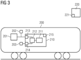
- FIG 3 shows a rail vehicle 200 with a control unit 210 for the rail vehicle 200.
- the control unit 210 is set up to load a dynamic model from a memory 211.
- the control unit has a processor 212, which is set up in FIG 1 method shown and/or that in FIG 2 carry out the procedures shown.
- the processor 212 can be set up to select a driving value, to use the dynamics model to calculate a control value with which the driving value is achieved and then to set the control value by outputting the control value via an output 213 to a drive 201 of the rail vehicle.
- the control value can be output to a braking device 202 via the output 213.
- control unit 210 can also be set up to check the dynamic model by comparing the driving values expected based on the set control values with real driving values, which are determined by means of a sensor 203 and read in via an input 214, and then, if necessary, the dynamic model in connection with FIG 1 explained, adjusted.
- the control unit 210 also has a radio module 215 with which the dynamics model can be sent to a central processing unit 220. This also has a radio module 221 for this purpose. Furthermore, it can be provided that the control unit 210 receives a dynamics model from the central processing unit 220.
Landscapes
- Engineering & Computer Science (AREA)
- Mechanical Engineering (AREA)
- Health & Medical Sciences (AREA)
- Biomedical Technology (AREA)
- General Health & Medical Sciences (AREA)
- Feedback Control In General (AREA)
Priority Applications (1)
| Application Number | Priority Date | Filing Date | Title |
|---|---|---|---|
| EP22195763.2A EP4339066A1 (fr) | 2022-09-15 | 2022-09-15 | Modèle dynamique pour véhicule ferroviaire |
Applications Claiming Priority (1)
| Application Number | Priority Date | Filing Date | Title |
|---|---|---|---|
| EP22195763.2A EP4339066A1 (fr) | 2022-09-15 | 2022-09-15 | Modèle dynamique pour véhicule ferroviaire |
Publications (1)
| Publication Number | Publication Date |
|---|---|
| EP4339066A1 true EP4339066A1 (fr) | 2024-03-20 |
Family
ID=83355333
Family Applications (1)
| Application Number | Title | Priority Date | Filing Date |
|---|---|---|---|
| EP22195763.2A Pending EP4339066A1 (fr) | 2022-09-15 | 2022-09-15 | Modèle dynamique pour véhicule ferroviaire |
Country Status (1)
| Country | Link |
|---|---|
| EP (1) | EP4339066A1 (fr) |
Citations (3)
| Publication number | Priority date | Publication date | Assignee | Title |
|---|---|---|---|---|
| US20190369627A1 (en) * | 2018-06-01 | 2019-12-05 | Thales Canada Inc | Self learning vehicle control system |
| US20210107543A1 (en) * | 2019-10-11 | 2021-04-15 | Progress Rail Services Corporation | Artificial intelligence based ramp rate control for a train |
| EP4035969A1 (fr) * | 2021-01-29 | 2022-08-03 | Siemens Mobility GmbH | Procédé d'apprentissage d'un dispositif commande pour véhicule ferroviaire, dispositif de commande et véhicule ferroviaire |
-
2022
- 2022-09-15 EP EP22195763.2A patent/EP4339066A1/fr active Pending
Patent Citations (3)
| Publication number | Priority date | Publication date | Assignee | Title |
|---|---|---|---|---|
| US20190369627A1 (en) * | 2018-06-01 | 2019-12-05 | Thales Canada Inc | Self learning vehicle control system |
| US20210107543A1 (en) * | 2019-10-11 | 2021-04-15 | Progress Rail Services Corporation | Artificial intelligence based ramp rate control for a train |
| EP4035969A1 (fr) * | 2021-01-29 | 2022-08-03 | Siemens Mobility GmbH | Procédé d'apprentissage d'un dispositif commande pour véhicule ferroviaire, dispositif de commande et véhicule ferroviaire |
Similar Documents
| Publication | Publication Date | Title |
|---|---|---|
| DE102012202914A1 (de) | Diagnoseverfahren und Diagnosevorrichtung für eine Fahrzeugkomponente eines Fahrzeugs | |
| DE102019126195A1 (de) | Verfahren zur effizienten, simulativen Applikation automatisierter Fahrfunktionen | |
| DE102019134053A1 (de) | Verfahren zur kontinuierlichen Absicherung im Fahrversuch applizierter automatisierter Fahrfunktionen | |
| DE102006028695A1 (de) | Elektronisches Steuersystem mit Fehlfunktionsüberwachung | |
| DE102018209108A1 (de) | Schnelle Fehleranalyse für technische Vorrichtungen mit maschinellem Lernen | |
| DE102013201031A1 (de) | Verfahren zur Inbetriebnahme zumindest eines Funktionsgeräts und Schienenfahrzeugsverband | |
| EP3460727A1 (fr) | Procédé d'analyse d'un comportement fonctionnel d'un système technique et unité d'évaluation | |
| EP4339066A1 (fr) | Modèle dynamique pour véhicule ferroviaire | |
| WO2005003972A2 (fr) | Procede pour verifier la securite et la fiabilite de systemes electroniques a base de logiciels | |
| EP4082868A1 (fr) | Procédé d'optimisation d'un trafic ferroviaire d'un réseau de trafic ferroviaire | |
| EP3714337B1 (fr) | Simulation de données de capteur modélisées de manière statistique | |
| DE10153447B4 (de) | Verfahren und Vorrichtung zur Programmierung eines Steuergeräts eines Fahrzeugs, insbesondere eines Kraftfahrzeugs | |
| WO2021219327A2 (fr) | Installation ferroviaire avec système de diagnostic et son procédé de fonctionnement | |
| DE102018222149A1 (de) | Verfahren zum Notbremsen eines zumindest teilautomatisiert geführten Kraftfahrzeugs | |
| DE102018202626A1 (de) | Verfahren zur rechnergestützten Parametrierung eines technischen Systems | |
| EP3603010A1 (fr) | Procédé de transmission de données d'un appareil vers un moyen de gestion de données, unité de transmission, appareil et système | |
| WO2022078770A1 (fr) | Procédé de production d'un modèle de comportement pour une flotte de véhicules automobiles au moyen d'un dispositif informatique électronique extérieur au véhicule automobile, et dispositif informatique électronique extérieur au véhicule automobile | |
| EP1117023B1 (fr) | Dispositif de diagnostic de fautes pendant le fonctionnement d'un véhicule automobile | |
| DE102021130866A1 (de) | Verfahren zum Ermitteln einer Fahrzeugmasse eines Fahrzeuges, Massen-Abschätzungseinheit sowie Fahrzeug | |
| WO2022084452A1 (fr) | Procédé de fonctionnement d'un système d'automatisation d'une machine ou d'une installation | |
| DE102020207921A1 (de) | Verfahren zum Einrichten eines Fahrzeugsimulationsmodells | |
| DE102018222150A1 (de) | Verfahren zum Notbremsen eines zumindest teilautomatisiert geführten Kraftfahrzeugs | |
| DE102019107240A1 (de) | Diagnoseverfahren, Diagnosesystem und Kraftfahrzeug | |
| DE112018007474T5 (de) | Übertragungssystem und übertragungsverfahren | |
| DE19748181B4 (de) | Verfahren zum Prüfen einer Funktion oder Einrichtung eines Fahrzeugs |
Legal Events
| Date | Code | Title | Description |
|---|---|---|---|
| PUAI | Public reference made under article 153(3) epc to a published international application that has entered the european phase |
Free format text: ORIGINAL CODE: 0009012 |
|
| STAA | Information on the status of an ep patent application or granted ep patent |
Free format text: STATUS: THE APPLICATION HAS BEEN PUBLISHED |
|
| AK | Designated contracting states |
Kind code of ref document: A1 Designated state(s): AL AT BE BG CH CY CZ DE DK EE ES FI FR GB GR HR HU IE IS IT LI LT LU LV MC MK MT NL NO PL PT RO RS SE SI SK SM TR |
|
| STAA | Information on the status of an ep patent application or granted ep patent |
Free format text: STATUS: REQUEST FOR EXAMINATION WAS MADE |
|
| 17P | Request for examination filed |
Effective date: 20240919 |
|
| RBV | Designated contracting states (corrected) |
Designated state(s): AL AT BE BG CH CY CZ DE DK EE ES FI FR GB GR HR HU IE IS IT LI LT LU LV MC MK MT NL NO PL PT RO RS SE SI SK SM TR |
|
| RAP3 | Party data changed (applicant data changed or rights of an application transferred) |
Owner name: SIEMENS MOBILITY GMBH |