EP4339039B1 - Procédé pour empêcher le déclenchement non d'airbags à partir de courts-circuits à des conducteurs d'autres coussins gonflables - Google Patents
Procédé pour empêcher le déclenchement non d'airbags à partir de courts-circuits à des conducteurs d'autres coussins gonflables Download PDFInfo
- Publication number
- EP4339039B1 EP4339039B1 EP24020036.0A EP24020036A EP4339039B1 EP 4339039 B1 EP4339039 B1 EP 4339039B1 EP 24020036 A EP24020036 A EP 24020036A EP 4339039 B1 EP4339039 B1 EP 4339039B1
- Authority
- EP
- European Patent Office
- Prior art keywords
- safety
- control device
- ecu
- operating state
- related control
- Prior art date
- Legal status (The legal status is an assumption and is not a legal conclusion. Google has not performed a legal analysis and makes no representation as to the accuracy of the status listed.)
- Active
Links
Images


Classifications
-
- B—PERFORMING OPERATIONS; TRANSPORTING
- B60—VEHICLES IN GENERAL
- B60R—VEHICLES, VEHICLE FITTINGS, OR VEHICLE PARTS, NOT OTHERWISE PROVIDED FOR
- B60R21/00—Arrangements or fittings on vehicles for protecting or preventing injuries to occupants or pedestrians in case of accidents or other traffic risks
- B60R21/01—Electrical circuits for triggering passive safety arrangements, e.g. airbags, safety belt tighteners, in case of vehicle accidents or impending vehicle accidents
- B60R21/017—Electrical circuits for triggering passive safety arrangements, e.g. airbags, safety belt tighteners, in case of vehicle accidents or impending vehicle accidents including arrangements for providing electric power to safety arrangements or their actuating means, e.g. to pyrotechnic fuses or electro-mechanic valves
Definitions
- Modern airbag control units typically include integrated circuits in which one integrated circuit preferably ignites several airbag squibs. Typically, one ignition circuit is provided for each squib, by means of which the relevant integrated circuit within the airbag control unit ignites the squib in the event of an accident and ensures that the airbag is deployed.
- a short circuit on a squib lead to the vehicle ground must not prevent or impair the ignition of the other squibs in the other ignition circuits.
- one or more of the supply lines of the squibs of an airbag ignition system may come into contact with electrically conductive parts of the bodywork as a result of the high, unpredictable mechanical impacts. This can cause very low-resistance short circuits between a supply line of a squib and the vehicle ground. If the ground supply line of the airbag control unit has a higher supply line resistance, a voltage drop compared to the actual vehicle ground can occur across this supply line resistance. As a result, the ground connection of the airbag control unit (GNDi) is then at a higher electrical potential than the connection of the squib that is short-circuited to the vehicle ground.
- diodes connect a connection of the squib that is short-circuited to the vehicle ground with the ground connection of the airbag control unit when the voltage difference between the vehicle ground and the potential of the ground connection of the airbag control unit is greater than the threshold voltage of the relevant diode.
- diodes connect a connection of the squib that is short-circuited to the vehicle ground with the ground connection of the airbag control unit when the vehicle ground is below the potential of the ground connection of the airbag control unit by more than the threshold voltage of the diode.
- the safety-relevant airbag control unit should in particular remain diagnosable and capable of igniting the squib propellant charges if fault influences such as those indicated above occur, where both short circuits to the vehicle ground and an increased GND resistance must be assumed.
- the short-circuited connections of the squib then potentially conduct the ground current, at least in part, into the vehicle ground due to the ground potential of the ground connection of the airbag control unit rising above the ground resistance. This leads to a substrate current injection in the relevant integrated circuit of the airbag control unit with the high potential of generating subsequent errors.
- Examples of state-of-the-art airbag circuits are the DE 10 2014 255 960 , the DE 39 25 594 A1 and the DE 3 738 862 A1 . From the DE 102 55 429 A1 a relevant device with functional autonomy is known.
- Safety-relevant systems such as airbag control units preferably have energy storage devices. These energy storage devices serve to provide at least temporary energy self-sufficiency. This self-sufficiency is necessary in the event of an interruption in the energy supply in connection with an accident. Airbag control units can preferably actively force this operating state of an emergency energy supply from the energy reserve.
- the power supply of the device can achieve self-sufficient operation via the operating mode typically available for airbag control units by means of self-supply (also called self-sufficient) from the energy reserve mentioned.
- This usually consists of corresponding capacitors of corresponding capacity.
- a designer typically prefers to design this capacity for the ignition processes after the vehicle's battery supply is lost. Potentially, the expert can apply this method to all systems with at least temporary self-sufficiency.
- the invention thus relates to methods for operating a safety-relevant control device for vehicles, in particular for an airbag control device.
- the control device has an energy reserve.
- the vehicle typically has an electrical on-board network with supply voltage lines.
- the control device receives signals from sensors and/or other systems.
- the safety-relevant control device has a first operating state and a second operating state.
- the energy consumption of the safety-relevant control device is preferably smaller in the first operating state than in the second operating state. Nevertheless, the safety-relevant control device can preferably perform its safety-relevant function in the first and second operating states.
- the method preferably comprises the step of providing an energy reserve.
- the method preferably comprises the step of evaluating the signals from the sensors and/or the other systems.
- the method preferably comprises the step of determining a safety-relevant event depending on the signals from the sensors and/or the other systems.
- the method preferably comprises the step of switching to the second operating state in the event of a safety-relevant event.
- the method preferably comprises the step of carrying out the safety-relevant function of the safety-relevant control device in the second operating state.
- the method is characterized by the step of supplying the safety-relevant control device from the energy reserve when the safety-relevant control device is in the second operating state.
- the safety-relevant control device In order to exclude any type of interference via the on-board network during an accident, the safety-relevant control device is only supplied with electrical energy in the first operating state from the vehicle's electrical on-board network using the supply voltage lines. For the same reason, the energy reserve is only charged with electrical energy in the first operating state from the vehicle's electrical on-board network using the supply voltage lines. If an accident occurs, the safety-relevant control device in the second operating state is separated from the vehicle's electrical on-board network and the supply voltage lines using a separating device as soon as possible after the safety-relevant event has been detected.
- This separation should preferably take place independently of the voltage difference between the potential of the relevant supply voltage lines on the one hand and the potential of a reference potential node of the safety-relevant control device on the other. This represents ensure that no energy flows from the energy reserve into the on-board network. Therefore, in the second operating state, the energy reserve is preferably also separated from the vehicle's electrical system and the supply voltage lines by means of a separating device. This separation means that any residual current that may still be flowing can no longer impair the function of the safety-relevant device.
- This separation of the energy reserve from the on-board network is of course preferably also carried out independently of the voltage difference between the potential of the relevant supply voltage lines on the one hand and the potential of a reference potential node of the safety-relevant control unit on the other.
- the proposed method preferably uses the same separating device for both separations. These can be transistors or other electrical switches.
- the safety-relevant control device preferably actuates these separating devices when they require actuation.
- the principle of the method can also be applied to the performance of safety-relevant tests.
- This is then a method for operating a safety-relevant control device for vehicles, in particular for an airbag control device, wherein the control device has an energy reserve, wherein the safety-relevant control device has a first operating state and a second operating state.
- the energy consumption from the battery of the safety-relevant control device is preferably higher in the first operating state than in the second operating state.
- the safety-relevant control device can perform its safety-relevant function, wherein the document presented here understands the performance of safety-relevant tests here as the performance of a safety-relevant function.
- the method then comprises the steps of providing an energy reserve, determining the need for a safety-relevant test, switching to the second operating state, performing the safety-relevant test by the safety-relevant control device in the second operating state and switching back to the first operating state.
- the method is characterized by the step of supplying the safety-relevant control device from the energy reserve when the safety-relevant control device is in the second operating state.
- a time slice control or a timer or another device can, for example, determine the need for a safety-relevant test.
- the safety-relevant control device has a connection to at least one further system component of the vehicle.
- Such further system components can be, for example, but not only, seat heaters or servomotors or similar, which the device does not need in relation to the safety function and whose function the device can dispense with at least temporarily or specifically in the event of an accident.
- the said connection between the safety-relevant control device and the further system component can be an analog or digital direct point-to-point connection between the safety-relevant control device and the further system component.
- a common data bus or the like can also establish such a connection.
- a higher-level computer unit to establish the connection between the safety-relevant control device and the further system component, which is connected to a first data bus and to a second, separate data bus.
- the safety-relevant control device is then connected, for example, to the first data bus and the further system component to the second data bus.
- the safety-relevant control device can then only communicate indirectly with the other system component via the higher-level computer unit.
- the problem now arises because the safety-relevant control device has a ground connection, the other system component has a first operating state and a second operating state, and the energy consumption of this other system component is higher in the first operating state than in the second operating state.
- the safety-relevant control device can cause the operating state of the other system components to change.
- the vehicle can therefore switch to an accident operating state in which the safety-relevant control device or a higher-level device switches off all unnecessary consumers, among other things to reduce the mass offsets.
- it can also be advantageous to temporarily switch less important system components to a power-saving operating state during normal operation in order to carry out safety-relevant tests.
- Such a method then preferably includes the step of determining the need for a safety-relevant test by the safety-relevant control device. Furthermore, such a method then preferably includes the step of switching the further system component to the second operating state of the further system component. Furthermore, such a method then preferably includes the step of carrying out the safety-relevant test by the safety-relevant control device. The further system component is in the second operating state of the further system component during the safety-relevant test. Finally, such a method then preferably includes the step of ending the safety-relevant test and switching the further system component back to the first operating state of the further system component.
- a higher-level control unit can provide and represent an indirect connection of the safety-relevant control device with other system components.
- the proposal presented here therefore relates to a method for operating a safety-relevant control device for vehicles, in particular for an airbag control device in a vehicle.
- the vehicle preferably has a further device (ECUVC), which is preferably a charging circuit (ECHVC) for the energy reserve (C) of the safety-relevant control device (ECU).
- ECUVC a charging circuit
- this charging circuit (ECUVC) supplies the control circuit (ECUIC) of the safety-relevant control device (ECU) and possibly other device parts of the safety-relevant control device (ECU) with electrical energy in the first operating state of the safety-relevant control device (ECU), i.e. in normal operation.
- the control device (ECU) has an internal ground contact (GNDi).
- the vehicle has another ground point (GND), typically the body of the vehicle as the vehicle ground.
- the control device comprises the energy reserve (C) already mentioned.
- the further device can be part of the safety-relevant control device (ECU).
- the additional device can be the charging circuit (ECUVC) of the safety-relevant device (ECU).
- the additional device can also be a device of the vehicle that is not part of the safety-relevant control device (ECU).
- Such an additional device can be, for example, a seat heater or the like.
- the current consumption of this additional device relevant to the problem discussed here contributes to an increase in the amount of the ground offset voltage ( ⁇ V GND ) in an active operating state.
- the safety-relevant control device (ECU) presented here or another device of the vehicle therefore switches off this additional device in the event of a safety-relevant incident, so that the additional device no longer feeds current into the ground line shared with the safety-relevant control device or only feeds a significantly lower current into this ground line.
- the additional device therefore has a current consumption of an electrical current for its operation in normal operation.
- This electrical current of the other device can lead to a ground offset with a ground offset voltage ( ⁇ V GND ) that is different from 0V.
- This ground offset voltage ( ⁇ V GND ) arises between the internal ground contact (GNDi) of the safety-relevant control device (ECU) on the one hand and the other ground point (GND) of the vehicle on the other.
- the other ground point (GND) can be, for example, the body as the vehicle ground.
- the short-circuited line in question can fall below the potential of the internal ground contact (GNDi) of the safety-relevant control unit (ECU).
- Such another line of the safety-relevant control device (ECU) can, for example, be a supply line a sensor of the safety-relevant control unit (ECU) or an ignition line (AS1, AS2) of a squib (SQ) of an airbag.
- AS1, AS2 ignition line
- SQ squib
- the latter case refers to the case of an airbag control system as a safety-relevant control unit (ECU).
- the control unit receives signals from sensors and/or other systems in the vehicle.
- data buses can connect these sensors and/or other systems on the one hand with the safety-relevant control unit (ECU) on the other hand electrically and/or using information technology. These connections can be wired or wireless. If they are wired, data buses such as the CAN data bus, the PSI5 data bus, the DSl3 data bus, the Lin data bus, PWM connections, simple digital and analogue lines and/or line bundles and the like are possible.
- a short circuit between such an electrical data bus and another ground point (GND) of the vehicle can lead to a similar effect.
- GND ground point
- Such a short circuit can, for example, be the short circuit of an electrical data bus with the body of the vehicle. This can then have the effect that the potential of the short-circuited data line is below the potential of the internal ground contact (GDi) of the safety-relevant control device (ECU).
- the safety-relevant control device has a first operating state for normal operation and a second operating state for when the safety-relevant function is being performed.
- the first operating state is the normal operating state without an accident and the second operating state is the state in which the airbag control device (ECU) detects an accident using its sensors and fires airbags.
- the document presented here proposes that the energy consumption of the safety-relevant control unit (ECU) in the first operating state be higher, i.e. normal, than in the second operating state. This has the advantage that the current flow via the electrical supply lines of the safety-relevant control device (ECU) is minimized as a result of the reduced current consumption.
- the safety-relevant control device In the first and second operating states, the safety-relevant control device (ECU) can perform its safety-relevant function. However, the control device should preferably switch to the second operating state in order to perform the safety-relevant function. It is therefore preferred that the safety-relevant device is in the first operating state during normal operation and in the second operating state when the safety-relevant function is being performed. In this document, this is described as a "can" statement, since the safety-relevant control device (ECU) can begin to perform the safety-relevant function while still in the first operating state before it has fully entered the second operating state. As already mentioned, the vehicle comprises the said additional device.
- the additional device preferably has a first current consumption when the control device (ECU) is in the first operating state and a second current consumption when the safety-relevant control device (ECU) is in the second operating state.
- the method presented in this document typically includes the step of providing an energy reserve (C).
- the method provides, for example, a capacitor (C) as an energy storage element of the safety-relevant control device (ECU) and preferably charges this capacitor (C) to a typically provided energy level using a charging circuit (ECUVC).
- a control circuit (ECUIC) of the safety-relevant control device (ECU) controls the charging process of the energy reserve (C) by the charging circuit (ECUVC) by means of a shutdown line and/or further control signals.
- the safety-relevant control circuit (ECUIC) of the safety-relevant control device (ECU) typically evaluates the signals from the sensors and/or the other systems during operation and, if necessary, concludes that a safety-relevant incident, for example an accident, has occurred. In the event of such a safety-relevant incident, the control circuit (ECUIC) of the safety-relevant control device (ECU) typically switches the safety-relevant control device (ECU) from the first operating state to the second operating state and causes the safety-relevant control device (ECU) to safety-relevant function, e.g. firing airbags.
- a safety-relevant incident for example an accident
- the method presented in this document therefore also includes the step of determining a safety-relevant event depending on the signals from the sensors and/or the other systems and the step of switching the operating state of the safety-relevant control device (ECU) to the second operating state in the event of a safety-relevant event (incident).
- the method proposed in this document provides for the safety-relevant function of the safety-relevant control device (ECU) to be carried out in the second operating state.
- the method proposed in this document provides for the safety-relevant control device (ECU) to be supplied from the energy reserve (C) instead of from the vehicle's on-board network via its supply lines when the safety-relevant control device (ECU) is in the second operating state.
- the method proposed in this document provides for making the greatest possible change in the current consumption of the additional device (ECUVC) in order to minimize the resulting ground offset in the form of a ground offset voltage ( ⁇ V) that drops across the parasitic ground resistance R GND on the ground supply voltage line. Therefore, the control circuit (ECUIC) of the safety-relevant control device (ECU) or another device in the vehicle preferably reconfigures the additional device.
- the additional device can be, for example, the charging circuit (ECUVC) of the safety-relevant device (ECU). This method step therefore preferably reprograms the additional device in such a way that the additional device then shows a second current consumption of the additional device (ECUVC) when the safety-relevant control device (ECU) is in the second operating state.
- the resulting ground offset drops across the parasitic ground resistance R GND on the ground supply voltage line in the form of a reduced ground offset voltage ( ⁇ V).
- ⁇ V reduced ground offset voltage
- the second current consumption of the additional device (ECUVC) in the second operating state of the safety-relevant control device (ECU) is typically smaller in magnitude than the first current consumption of the additional device (ECUVC) in the first operating state of the safety-relevant control device (ECU). If this is fulfilled, the ground offset voltage ( ⁇ V GND ) in the second operating state of the safety-relevant control device (ECU) is reduced compared to the first operating state of the control device (ECU), thus increasing the robustness and operational reliability.
- the document presented here includes a second, similar method for operating a safety-relevant control device (ECU) for vehicles, in particular for an airbag control device.
- the method assumes that the control device has an energy reserve and that the vehicle has an electrical system with supply voltage lines.
- one supply voltage line is the body ground of the vehicle.
- These supply voltage lines include a supply voltage line that is at the supply voltage opposite the vehicle ground and which the document presented here also refers to as the supply voltage (V bat ).
- the control device (ECU) receives signals from sensors and/or other systems.
- the safety-relevant control device (ECU) should also again have a first operating state and a second operating state.
- the energy consumption of the safety-relevant control device is higher in the first operating state than in the second operating state.
- the safety-relevant control device can perform its safety-relevant function in this second method in the first and second operating states as before.
- the document presented here now describes a second method with a step of providing the energy reserve (C). Again, we refer here to the above explanations for the first method, which also apply here.
- the document presented here now describes a second method with a step of evaluating the signals from the sensors and/or the other systems. Again, we refer here to the above explanations for the first method, which also apply here.
- the second method also includes the step of determining a safety-relevant event depending on the signals from the sensors and/or the other systems. Again, we refer here to the above explanations for the first method, which also apply here.
- the second method as in the first method, there is a step of switching to the second operating state in the event of a safety-relevant event. Again, we refer to the above explanations for the first method, which also apply here.
- the second method also includes a step of carrying out the safety-relevant function of the safety-relevant control device in the second operating state. Again, we refer to the above explanations for the first method, which also apply here.
- the safety-relevant control device (ECU) is supplied with electrical energy in the first operating state from the vehicle's electrical system using the supply voltage lines.
- the second method includes charging the energy reserve (C) in the first operating state from the electrical system of the vehicle by means of the supply voltage lines with electrical energy.
- the second method comprises the step of isolating the safety-relevant control device (ECU) in the second operating state from the electrical system of the vehicle, in particular from the supply voltage lines, in particular from the supply voltage (V bat ) by means of a isolating device.
- the technical teaching of the document presented here is expressly intended to include the combination of this procedure of the second method with the procedure of the first method, even if they differ slightly.
- ground offset in the form of the ground offset voltage ( ⁇ V GND ) is minimized in the event of a safety-relevant incident.
- This separation in the second method takes place independently of the voltage difference between the potential of the relevant supply voltage lines (GND) on the one hand and the potential of a reference potential node (GNDi) of the safety-relevant control device (ECU) on the other.
- GND relevant supply voltage lines
- GNDi reference potential node
- the separation device only separates the supply voltage (V bat ) from the safety-relevant control device, preferably at least from the safety-relevant control circuit (ECUIC).
- the separation device is a transistor which the safety-relevant control circuit (ECUIC) of the safety-relevant control device (ECU) or, less preferably, another sub-device of the safety-relevant control device (ECU) controls by means of a separation signal, which can also be the shutdown signal (ECUVCL), for example.
- this separation takes place independently of the voltage difference between the potential of the relevant supply voltage lines, and preferably from the potential of the vehicle ground (GND), on the one hand, and the potential of a reference potential node (GNDi) of the safety-relevant control device on the other.
- the safety-relevant control device ECU
- the safety-relevant control device is preferably supplied with electrical energy from the energy of the energy reserve (C) when the safety-relevant control device is in the second operating state.
- the first separation and the second separation can be the same process.
- a single separation device can separate the electrical connection of the energy reserve (C) and the control circuit (ECUIC) of the control device to the supply voltage (V bat ). This connection can be made indirectly, for example via the charging circuit (ECUVC).
- the separation device can be part of the charging circuit, for example the switching transistor of a switching regulator of the charging circuit.
- the document presented here includes a third, similar method for operating a safety-relevant control device for vehicles, in particular for an airbag control device.
- this third method again assumes that the safety-relevant control device (ECU) has an energy reserve and that the vehicle has an electrical on-board network with supply voltage lines.
- the statements on this point in the two descriptions of the two preceding methods typically apply to all three methods.
- the supply voltage lines should include a supply voltage (V bat ).
- V bat supply voltage
- the statements on this point in the two descriptions of the two preceding methods typically apply to all three methods.
- the safety-relevant control device should again have a first operating state and a second operating state in this method. The statements on this point in the two descriptions of the two preceding methods typically apply to all three methods.
- the energy consumption of the safety-relevant control device should again be higher in the first operating state of the safety-relevant control device than in the second operating state of the safety-relevant control device.
- the statements on this point in the two descriptions of the two preceding methods typically apply to all three methods.
- the safety-relevant control device can again perform its safety-relevant function.
- the statements on this point in the two descriptions of the two preceding methods typically apply to all three methods.
- the third method presented here again includes the step of providing an energy reserve (C).
- C energy reserve
- the safety-relevant control circuit (ECUIC) of the safety-relevant control device (ECU) carries out a step of determining the need for a safety-relevant test.
- the control circuit (ECUIC) of the safety-relevant control device (ECU) then carries out, as proposed, a switchover of the safety-relevant control device (ECU) to the second operating state of the safety-relevant control device (ECU).
- the step of carrying out the safety-relevant test by the safety-relevant control device (ECU) in the second operating state of the safety-relevant control device then follows.
- the safety-relevant control circuit (ECUIC) of the safety-relevant control device (ECU) carries out this test.
- the safety-relevant control circuit (ECUIC) of the safety-relevant control device (ECU) typically switches the safety-relevant control device (ECU) back to the first operating state of the safety-relevant control device (ECU).
- the said charging circuit (ECUVC) of the control device (ECU) supplies the safety-relevant control device (ECU) with electrical energy in the first operating state from the vehicle's electrical system by means of the supply voltage lines.
- the said charging circuit (ECUVC) of the control device (ECU) charges the energy reserve (C) with electrical energy in the first operating state from the vehicle's electrical system by means of the supply voltage lines.
- the third method presented here provides for the safety-relevant control device (ECU) to be separated in the second operating state from the vehicle's electrical system, in particular from the supply voltage lines, in particular from the supply voltage (V bat ), by means of a separating device in a first separation.
- the above statements on the separating device typically also apply here.
- this first separation takes place independently of the voltage difference, whereby this voltage difference is present between the potential of the relevant supply voltage lines on the one hand and the potential of a reference potential node on the other.
- the potential of the relevant supply voltage lines typically refers in particular to the potential of the vehicle ground (GND) in this document.
- the potential of the reference node typically refers in particular to the potential of the internal ground (GNDi) of the safety-relevant control device (ECU).
- the third method provides for the energy reserve in the second operating state to be separated from the vehicle's electrical system and the supply voltage lines by means of a separating device in a second separation.
- This second separation is also typically carried out independently of the voltage difference between the potential of the relevant supply voltage lines (GND) on the one hand and the potential of a reference potential node (GNDi) of the safety-relevant control unit on the other.
- the document presented here expressly refers to the above statements on the first and second separation and the separating device in connection with the description of the first and second methods. These statements also apply here.
- the process of the first separation can be carried out immediately that of the second separation.
- the safety-relevant control device (ECU) is supplied from the energy reserve (C) according to the third method when the safety-relevant control device (ECU) is in the second operating state of the safety-relevant control device (ECU).
- the control device has a connection to at least one further system component of the vehicle.
- the safety-relevant control device has a ground connection (GNDi).
- This further system component also has a first operating state and a second operating state. The energy consumption of this further system component is preferably higher in the first operating state than in the second operating state.
- operation of the further system component in the first operating state of the further system component can cause a first additional ground offset of the potential of the ground connection of the safety-relevant control device (GNDi) compared to a reference potential.
- the reference potential can be the vehicle ground (GND).
- Operating the additional system component in the second operating state of the additional system component can cause a second additional ground offset of the potential of the ground connection (GNDi) of the safety-relevant control device (ECU) compared to a reference potential (e.g. GND), which can also be 0V.
- the amount of the first ground offset is greater due to the greater current consumption than the amount of the second ground offset due to the then lower current consumption.
- the additional system component of the vehicle is therefore particularly relevant in this case if the ground current of the additional system component of the vehicle flows via the same ground line as the ground line of the safety-relevant control device (ECU). The ground current then causes an additional voltage drop across the ground resistance (R GND ) and thus an additional ground offset ( ⁇ V GND ).
- the safety-relevant control device can cause a change in the operating state of the additional system component.
- the technical teaching presented here suggests that the safety-relevant control unit (ECU) determines the need for a safety-relevant test if necessary.
- the process variant presented here then provides for the switching of the other system component to the second operating state of the other system component. This is followed by the execution of the safety-relevant tests by the safety-relevant control unit (ECU), whereby the additional system component is in the second operating state of the additional system component during the safety-relevant test.
- the safety-relevant test is preferably terminated and the additional system component is switched back to the first operating state of the additional system component.
- a first sub-variant of the previously presented method variant is a method that is characterized in that a higher-level control unit provides the connection of the safety-relevant control device (ECU) with other system components, in particular the previously mentioned further system component, indirectly, for example via a CAN data bus with the safety-relevant control device (ECU).
- the safety-relevant control device (ECU) preferably has a data bus connection for such a data bus, for example a CAN bus or a CAN-FD data bus.
- the method variant can also be a variant of the method variants previously presented if the proposed device carries out these methods simultaneously.
- This second method variant is characterized in that the safety-relevant control device (ECU) comprises a control circuit (ECUIC) of the safety-relevant control device (ECU) and that the method comprises switching off the power consumption of another device (ECUVC), in particular by means of a switch-off line (ECUVCL), in the second operating state of the control device (ECU).
- ECUVC control circuit
- ECUVCL switch-off line
- the method variant can also be a variant of the previously presented method variants if the proposed device executes these methods simultaneously.
- This third method variant preferably includes influencing the power consumption of the further device (ECUVC) by the safety-relevant control device (ECU) or a device part of the safety-relevant control device (ECU). These preferably use a Shutdown line (ECUVCL) for this influence.
- the said device part of the safety-relevant control device (ECU) can in particular be a control circuit (ECUIC) of the safety-relevant control device (ECU).
- the influence is preferably carried out depending on the operating state of the control device (ECU).
- the influence is particularly preferably carried out by means of a shutdown line (ECUVCL).
- the control circuit (ECUIC) of the safety-relevant control device (ECU) signals the further device, which is for example the said charging circuit (ECUVC), to reduce its current consumption.
- this preferably comprises, for example, a transistor as a separating device.
- the shutdown line (ECUVCL) controls, for example, this transistor and thus the separating device.
- the control circuit (ECUIC) of the safety-relevant control device (ECU) preferably separates the direct or indirect connection of the energy reserve (C) and/or the control circuit (ECUIC) from the supply voltage (V bat ), for example by means of such a signaling.
- the current consumption of the further device (ECUVC) is therefore preferably greater in the first operating state of the control device (ECU) than in the second operating state of the safety-relevant control device (ECU).
- This sub-variant of the method is characterized in that the further device is a charging circuit (ECUVC) of the safety-relevant control device (ECU).
- the method comprises charging the energy reserve (C) by the charging circuit in the first operating state of the control device (ECU) and supplying a control circuit (ECUIC) of the control device (ECU) with electrical energy from the charging circuit (ECUVC) in the first operating state of the control device (ECU).
- the method in this sub-variant comprises supplying the control circuit (ECUIC) of the control device (ECU) with electrical energy from the energy reserve (C) in the second operating state of the control device (ECU).
- Such a supply of the safety-relevant control device via the energy reserve during the execution of the safety-relevant function reduces the attack surface of an accident event in relation to a safety-relevant impact on the safety-relevant Control device.
- a wiring harness is distributed throughout the vehicle.
- the supply from the energy reserve which is also preferably installed near or, better still, in the safety-relevant control device, significantly reduces the probability of the accident event having a functionally impairing effect on the safety-relevant device.
- Avoiding substrate current effects may require relevant chip area increases in the integrated circuit for clearances or guard rings or internal protection diodes and/or external voltage limiting measures. Therefore, a much more cost-effective solution to the problem is to minimize or avoid the battery supply currents as a cause by using the energy reserve already present in airbag systems to power the airbag control device as proposed here.
- the proposed operating mode is a significantly more cost-effective/cost-neutral implementation in case of requirements for robustness against a faulty ground offset in the event of other faults such as short circuits in the vehicle's system.
- the designer can also potentially dispense with external protective measures to maintain the safe operating areas or SOA (elimination of EOS) through the flexible use of power consumption-reducing measures such as autarky/self-sufficiency or reduce the resulting effort for protective measures.
- SOA laminate of EOS
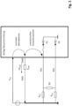
- Figure 1 shows a relevant state of the art. Due to the ground resistance (R GND ), the ground offset is dropped as a voltage ( ⁇ V GND ) across the ground resistance (R GND ) of the ground lead of the airbag control device.
- the airbag control device controls the squib (SQ) of the airbag via a first control line (AS1) and a second control line (AS2). If, for example, in the event of an accident, a low-resistance short circuit occurs between the first control line (AS1) and the vehicle ground (GND), the supply voltage (V bat ) feeds a current into the airbag control device.
- the internal ground (GNDi) of the control device is at a potential that is the ground offset ( ⁇ V GND ) above the potential of the vehicle ground (GND).
- the supply voltage (V bat ) therefore also feeds a current into the safety-relevant control device (ECU).
- This injected current flows through the control line (AS1, AS2) short-circuited with the vehicle ground (GND) to the vehicle ground.
- this current is fed by the supply voltage line (V bat ) into the substrate of the control device, where it can cause effects that are difficult to predict.
- such injected currents can switch parasitic bipolar transistors.
- the first diode (D1) and the second diode (D2) are intended to symbolize ESD protection structures.
- Figure 2 corresponds to the Figure 1 with the difference that the third diode (D3) and the fourth diode (D4) now take over the current when the voltage difference between the internal ground (GNDi) and the vehicle ground (GND) is greater than the threshold voltage of these diodes.
- Figure 2 is state of the art.
- Figure 3 is intended to illustrate the state of the method according to the invention in the second operating state in a schematic and simplified manner.
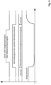
- FIG. 4 shows the time sequence in principle and in a roughly simplified manner.
- the control device changes from the first operating state with a higher energy consumption to the second operating state with a lower energy consumption.
- the energy reserve (C) supplies the control device with energy and as a result the battery current drops.
- the control device then carries out the ignition or diagnostic event.
- the airbag control device ignites the ignition pills for which such a Ignition was intended.
- the control device could also carry out a test in this second operating state, in other words carry out a diagnostic event.
- the control device After the second operating state has ended, the control device returns to the first operating state.
- the battery current from the operating voltage source via the supply voltage line (V bat ) increases again.
- the current in the supply voltage line (V bat ) is higher at this time than before the energy reserve (C) was used.
- the supply voltage (V bat ) then recharges the energy reserve (C), which is typically a capacitor. This requires an additional charging current for the duration of the temporal charging phase.
- FIG 5 shows a proposed device that carries out the proposed method.
- the device comprises a voltage source (V batsup) of the vehicle.
- the voltage source (V batsup ) of the vehicle generates the potential of the supply voltage (V bat ) compared to the potential of the vehicle ground (GND).
- the safety-relevant control device (ECU) comprises in the example of the Figure 5 as a further device, a charging circuit (ECUVC).
- the charging circuit takes electrical power from the supply voltage (V bat ) and the ground contact of the safety-relevant control device (ECU), which represents the internal ground of the safety-relevant control device (ECU).
- the charging circuit (ECUVC) charges the energy reserve (C) in the form of a capacitor, for example, to the potential of an internal supply voltage (V bati ).
- the charging circuit (ECUVC) also supplies the control circuit (ECUIC) of the safety-relevant control device (ECU) with electrical energy via the internal supply voltage (V bati ).
- the safety-relevant control circuit (ECUIC) and the charging circuit (ECHVC) can be manufactured as a single piece, monolithically integrated on a semiconductor crystal.
- the safety-relevant control circuit (ECUIC) of the safety-relevant control device (ECU) can switch the charging circuit from the first operating state to a second operating state via a shutdown line (ECUVCL).
- the charging circuit (ECUVC) does not charge the energy reserve (C) in the form of a capacitor.
- the charging circuit (ECUVC) supplies the control circuit (ECUIC) of the safety-relevant control device (ECU) with electrical energy.
- the energy reserve (C) supplies the safety-relevant control circuit (ECUIC) of the safety-relevant control device (ECU) and, if applicable, other sub-devices of the safety-relevant control device (ECU) with electrical energy.
- the current consumption of the charging circuit (ECUIC) and thus of the safety-relevant control device (ECU) is therefore reduced in the second operating state.
- the internal ground point (GNDi) of the safety-relevant control device (ECU) is connected to the vehicle ground (GND) via the parasitic ground resistance (R GND ). This parasitic ground resistance (R GND ) is typically often around 2 Ohm.
- the ground offset has a ground offset voltage ( ⁇ V GND ).
- ⁇ V GND ground offset voltage
- the ground offset can then be different from 0V. This ground offset can therefore lead to the problems described above in the event of a short circuit (SC1, SC2) between a connection line of the safety-relevant control device (ECU) and the vehicle ground (GND).
- the Figure 5 shows an example of an airbag control device as a safety-relevant control device (ECU).
- the safety-relevant control device (ECU) is connected to several ignition caps via connecting lines.
- one ignition cap (SQ) of the ignition caps is connected to the safety-relevant control device (ECU) with a first connecting line (AS1) and a second connecting line (AS2).
- the safety-relevant control device (ECU) evaluates signals from sensors (SO).
- an exemplary sensor (SO) is connected to the safety-relevant control circuit (ECUIC) of the safety-relevant control device (ECU) via a sensor line (SOL).
- the safety-relevant control device (ECU) now implements the safety-relevant function in such a way that it detects a safety-relevant incident, for example an accident, with the help of one or more sensors (SO).
- the safety-relevant control device (ECU) preferably communicates with the sensors via the sensor lines (SOL).
- the sensor lines can be a PSl5 data bus or a DSI3 data bus or the like.
- ECU safety-relevant control circuit
- the safety-relevant control circuit (ECUIC) of the safety-relevant control device (ECU) detects such a safety-relevant incident, for example an accident, the safety-relevant control device (ECUIC) carries out its safety-relevant function.
- This is the ignition of the squib (SQ) to deploy the airbags of the exemplary airbag system.
- a first short circuit (SC1) can occur between the first connection line (AS1) of the ignition cap (SQ) and the vehicle ground (GND).
- a second short circuit (SC2) can also occur between the second connection line (AS2) of the ignition cap (SQ) and the vehicle ground (GND).
- a third short circuit can occur between the sensor connection line (SOL) of a sensor (SO) and the vehicle ground (GND).
- SOL sensor connection line
- GND vehicle ground
- other short circuits between connections of the safety-relevant control device (ECU) and the vehicle ground (GND) can also occur, which can have a similar destructive effect.
- the short circuits (SC1, SC2, SC3) in the Figure 5 are therefore only examples.
- the safety-relevant control device (ECU) or another higher-level device tries to minimize the power consumption of the devices whose operating current is diverted to the vehicle ground via the same ground line.
Landscapes
- Engineering & Computer Science (AREA)
- Mechanical Engineering (AREA)
- Air Bags (AREA)
Claims (6)
- Procédé de fonctionnement d'un dispositif de commande (ECU) relatif à la sécurité pour des véhicules, en particulier pour un dispositif de commande d'airbag, dans lequel- le dispositif de commande (ECU) présente une réserve d'énergie (C), et- le véhicule présentant un réseau de bord électrique avec des lignes de tension d'alimentation, et- les lignes de tension d'alimentation comprenant une tension d'alimentation (Vbat), et- dans lequel le dispositif de commande (ECU) relatif à la sécurité présente un premier état de fonctionnement et un deuxième état de fonctionnement, et dans lequel- la consommation d'énergie du dispositif de commande relatif à la sécurité (ECU) dans le premier état de fonctionnement du dispositif de commande relatif à la sécurité (ECU) est supérieure en valeur absolue à celle dans le deuxième état de fonctionnement du dispositif de commande relatif à la sécurité (ECU), et dans lequel- dans le premier et le deuxième état de fonctionnement du dispositif de commande (ECU) relatif à la sécurité, le dispositif de commande (ECU) relatif à la sécurité peut exercer sa fonction relative à la sécurité,avec les étapes suivantes- mise à disposition de la réserve d'énergie (C);- détermination de la nécessité d'un test relatif à la sécurité;- commutation du dispositif de commande (ECU) relatif à la sécurité dans le deuxième état de fonctionnement du dispositif de commande (ECU) relatif à la sécurité;- exécution du test relatif à la sécurité par le dispositif de commande (ECU) relatif à la sécurité dans le deuxième état de fonctionnement du dispositif de commande (ECU) relatif à la sécurité;- le retour du dispositif de commande (ECU) relatif à la sécurité au premier état de fonctionnement du dispositif de commande (ECU) relatif à la sécurité;caractérisé par les étapes consistant à- alimenter en énergie électrique le dispositif de commande (ECU) relatif à la sécurité dans le premier état de fonctionnement à partir du réseau électrique de bord du véhicule au moyen des lignes de tension d'alimentation, et- charger la réserve d'énergie (C) dans le premier état de fonctionnement à partir du réseau électrique de bord du véhicule au moyen des lignes de tension d'alimentation avec de l'énergie électrique et- séparation dans une première séparation du dispositif de commande (ECU) relatif à la sécurité dans le deuxième état de fonctionnement du réseau électrique de bord du véhicule et plus particulièrement des lignes de tension d'alimentation et plus particulièrement de la tension d'alimentation (V bat) au moyen d'un dispositif de séparation,- cette première séparation s'effectuant indépendamment de la différence de tension entre le potentiel des lignes de tension d'alimentation concernées (GND) d'une part et le potentiel d'un noeud de potentiel de référence (GNDi) du dispositif de commande (ECU) relevant de la sécurité d'autre part, et- séparation dans une deuxième séparation de la réserve d'énergie (C) dans le deuxième état de fonctionnement du réseau électrique de bord du véhicule et des lignes de tension d'alimentation au moyen d'un dispositif de séparation,- cette deuxième séparation s'effectuant indépendamment de la différence de tension entre le potentiel des lignes de tension d'alimentation concernées (GND) d'une part et le potentiel d'un noeud de potentiel de référence (GNDi) du dispositif de commande (ECU) relevant de la sécurité d'autre part, et- la première séparation pouvant être égale à la deuxième séparation et- l'alimentation du dispositif de commande relatif à la sécurité à partir de la réserve d'énergie lorsque le dispositif de commande relatif à la sécurité se trouve dans le deuxième état de fonctionnement du dispositif de commande relatif à la sécurité.
- Procédé de fonctionnement d'un dispositif de commande relatif à la sécurité selon la revendication 1,- dans lequel le dispositif de commande présente une connexion à au moins un autre composant de système du véhicule et- dans lequel le dispositif de commande relatif à la sécurité présente une connexion de masse et- dans lequel cet autre composant de système présente un premier état de fonctionnement et un deuxième état de fonctionnement, et- la consommation d'énergie de cet autre composant du système est plus élevée dans le premier état de fonctionnement que dans le deuxième état de fonctionnement, et- un fonctionnement de l'autre composant de système dans le premier état de fonctionnement de l'autre composant de système provoquant un premier décalage de masse supplémentaire du potentiel de la borne de masse du dispositif de commande relatif à la sécurité par rapport à un potentiel de référence, et- un fonctionnement de l'autre composant du système dans le deuxième état de fonctionnement de l'autre composant du système provoquant un deuxième décalage de masse supplémentaire du potentiel de la borne de masse du dispositif de commande relatif à la sécurité par rapport au potentiel de référence, qui peut également être DV, et- la valeur du premier décalage de masse supplémentaire étant supérieure à la valeur du deuxième décalage de masse supplémentaire, et- dans lequel le dispositif de commande relatif à la sécurité peut provoquer un
changement de l'état de fonctionnement de l'autre composant du système, avec les étapes suivantes- détermination de la nécessité d'un test relatif à la sécurité par le dispositif de commande relatif à la sécurité (ECU);- commutation de l'autre composant du système sur le deuxième état de fonctionnement de l'autre composant du système;- Exécution du test relatif à la sécurité par le dispositif de commande relatif à la sécurité,- l'autre composant du système se trouvant dans le deuxième état de fonctionnement de l'autre composant du système pendant le test relatif à la sécurité;- terminer le test relatif à la sécurité et remettre l'autre composant du système dans le premier état de fonctionnement de l'autre composant du système. - Procédé d'exploitation d'un dispositif de commande relatif à la sécurité selon la revendication 2,
caractérisé en ce que- en ce qu'une unité de commande supérieure fournit la connexion indirecte du dispositif de commande relatif à la sécurité avec d'autres composants du système. - Procédé selon la revendication 1, dans lequel il peut également s'agir simultanément d'un procédé selon les revendications 2 à 3, caractérisé en ce que- le dispositif de commande relatif à la sécurité (ECU) comprend un circuit de commande (ECUIC) du dispositif de commande relatif à la sécurité (ECU), et- le procédé comprend la coupure de la consommation de courant d'un autre dispositif (ECUVC), notamment au moyen d'une ligne de coupure (ECUVCL), dans le deuxième état de fonctionnement du dispositif de commande (ECU).
- Procédé selon la revendication 4, sachant qu'il peut également s'agir simultanément d'un procédé selon les revendications 1 à 3, caractérisé,- en ce que le procédé comprend l'influence de la consommation de courant de l'autre dispositif (ECUVC), notamment au moyen d'une ligne de coupure (ECUVCL), par le dispositif de commande (ECU) relatif à la sécurité ou une partie de dispositif du dispositif de commande (ECU) relatif à la sécurité, notamment un circuit de commande (ECUIC) du dispositif de commande (ECU) relatif à la sécurité, en fonction de l'état de fonctionnement du dispositif de commande (ECU),- la consommation de courant de l'autre dispositif (ECUVC) étant plus importante dans le premier état de fonctionnement du dispositif de commande (ECU) que dans le deuxième état de fonctionnement du dispositif de commande (ECU) relatif à la sécurité.
- Procédé selon la revendication 4 ou 5, caractérisé en ce que- l'autre dispositif est un circuit de charge (ECUVC) du dispositif de commande (ECU) relatif à la sécurité, et- le procédé comprend la charge de la réserve d'énergie (C) par le circuit de charge dans le premier état de fonctionnement du dispositif de commande (ECU), et- le procédé comprend l'alimentation d'un circuit de commande (ECUIC) du dispositif de commande (ECU) avec l'énergie électrique du circuit de charge (ECUVC) dans le premier état de fonctionnement du dispositif de commande (ECU) et- le procédé comprend l'alimentation du circuit de commande (ECUIC) du dispositif de commande (ECU) avec l'énergie électrique de la réserve d'énergie (C) dans le deuxième état de fonctionnement du dispositif de commande (ECU).
Applications Claiming Priority (3)
| Application Number | Priority Date | Filing Date | Title |
|---|---|---|---|
| DE102020126014.8A DE102020126014B4 (de) | 2020-10-05 | 2020-10-05 | Verfahren zur Verhinderung der Nichtauslösung von Airbags durch Kurzschlüsse an Zuleitungen anderer Airbags |
| EP21777627.7A EP4225615B1 (fr) | 2020-10-05 | 2021-09-08 | Procédé destiné à empêcher le non-déploiement de coussins de sécurité gonflables par des courts-circuits sur des lignes d'alimentation d'autres coussins de sécurité gonflables |
| PCT/DE2021/100742 WO2022073538A1 (fr) | 2020-10-05 | 2021-09-08 | Procédé destiné à empêcher le non-déploiement de coussins de sécurité gonflables par des courts-circuits sur des lignes d'alimentation d'autres coussins de sécurité gonflables |
Related Parent Applications (2)
| Application Number | Title | Priority Date | Filing Date |
|---|---|---|---|
| EP21777627.7A Division-Into EP4225615B1 (fr) | 2020-10-05 | 2021-09-08 | Procédé destiné à empêcher le non-déploiement de coussins de sécurité gonflables par des courts-circuits sur des lignes d'alimentation d'autres coussins de sécurité gonflables |
| EP21777627.7A Division EP4225615B1 (fr) | 2020-10-05 | 2021-09-08 | Procédé destiné à empêcher le non-déploiement de coussins de sécurité gonflables par des courts-circuits sur des lignes d'alimentation d'autres coussins de sécurité gonflables |
Publications (4)
| Publication Number | Publication Date |
|---|---|
| EP4339039A2 EP4339039A2 (fr) | 2024-03-20 |
| EP4339039A3 EP4339039A3 (fr) | 2024-06-19 |
| EP4339039C0 EP4339039C0 (fr) | 2024-12-18 |
| EP4339039B1 true EP4339039B1 (fr) | 2024-12-18 |
Family
ID=77914210
Family Applications (3)
| Application Number | Title | Priority Date | Filing Date |
|---|---|---|---|
| EP24020035.2A Active EP4353544B1 (fr) | 2020-10-05 | 2021-09-08 | Procédé pour empêcher le déclenchement non d'airbags à partir de courts-circuits à des conducteurs d'autres coussins gonflables |
| EP21777627.7A Active EP4225615B1 (fr) | 2020-10-05 | 2021-09-08 | Procédé destiné à empêcher le non-déploiement de coussins de sécurité gonflables par des courts-circuits sur des lignes d'alimentation d'autres coussins de sécurité gonflables |
| EP24020036.0A Active EP4339039B1 (fr) | 2020-10-05 | 2021-09-08 | Procédé pour empêcher le déclenchement non d'airbags à partir de courts-circuits à des conducteurs d'autres coussins gonflables |
Family Applications Before (2)
| Application Number | Title | Priority Date | Filing Date |
|---|---|---|---|
| EP24020035.2A Active EP4353544B1 (fr) | 2020-10-05 | 2021-09-08 | Procédé pour empêcher le déclenchement non d'airbags à partir de courts-circuits à des conducteurs d'autres coussins gonflables |
| EP21777627.7A Active EP4225615B1 (fr) | 2020-10-05 | 2021-09-08 | Procédé destiné à empêcher le non-déploiement de coussins de sécurité gonflables par des courts-circuits sur des lignes d'alimentation d'autres coussins de sécurité gonflables |
Country Status (4)
| Country | Link |
|---|---|
| EP (3) | EP4353544B1 (fr) |
| CN (1) | CN116323330B (fr) |
| DE (1) | DE102020126014B4 (fr) |
| WO (1) | WO2022073538A1 (fr) |
Family Cites Families (7)
| Publication number | Priority date | Publication date | Assignee | Title |
|---|---|---|---|---|
| DE3738862A1 (de) | 1987-11-16 | 1989-05-24 | Bosch Gmbh Robert | Verfahren zum betrieb einer sicherheitseinrichtung fuer fahrzeuginsassen |
| DE3925594A1 (de) | 1988-08-26 | 1990-03-01 | Bosch Gmbh Robert | Elektronische einrichtung und betriebsverfahren |
| DE10255429A1 (de) | 2002-11-28 | 2004-06-09 | Conti Temic Microelectronic Gmbh | Verfahren zum Betreiben einer aus einer Betriebsspannungsquelle versorgten elektronischen Baugruppe |
| ATE380718T1 (de) * | 2004-05-28 | 2007-12-15 | Catem Develec Gmbh | Elektronischer batterieschutzschalter |
| DE102008040145A1 (de) * | 2008-07-03 | 2010-01-07 | Robert Bosch Gmbh | Vorrichtung zur Ansteuerung aller Airbags für ein Fahrzeug, Steuergerät zur Bildung eines Ansteuersignals für alle Airbags für ein Fahrzeug und ein System aus der Vorrichtung und dem Steuergerät |
| EP2497692B1 (fr) * | 2011-03-07 | 2013-03-06 | Autoliv Development AB | Commande pour airbag |
| DE102014225960A1 (de) * | 2014-12-16 | 2016-06-16 | Robert Bosch Gmbh | Überwachungsvorrichtung für zumindest einen Zündkreis für ein Personenschutzmittel für ein Fahrzeug und Verfahren zum Betreiben einer Überwachungsvorrichtung |
-
2020
- 2020-10-05 DE DE102020126014.8A patent/DE102020126014B4/de active Active
-
2021
- 2021-09-08 EP EP24020035.2A patent/EP4353544B1/fr active Active
- 2021-09-08 CN CN202180064892.XA patent/CN116323330B/zh active Active
- 2021-09-08 WO PCT/DE2021/100742 patent/WO2022073538A1/fr not_active Ceased
- 2021-09-08 EP EP21777627.7A patent/EP4225615B1/fr active Active
- 2021-09-08 EP EP24020036.0A patent/EP4339039B1/fr active Active
Also Published As
| Publication number | Publication date |
|---|---|
| EP4225615A1 (fr) | 2023-08-16 |
| DE102020126014B4 (de) | 2022-07-07 |
| WO2022073538A1 (fr) | 2022-04-14 |
| CN116323330A (zh) | 2023-06-23 |
| EP4225615B1 (fr) | 2025-10-29 |
| DE102020126014A1 (de) | 2022-04-21 |
| EP4339039C0 (fr) | 2024-12-18 |
| CN116323330B (zh) | 2023-11-24 |
| EP4353544A3 (fr) | 2024-06-19 |
| EP4225615C0 (fr) | 2025-10-29 |
| EP4339039A2 (fr) | 2024-03-20 |
| EP4353544B1 (fr) | 2024-11-20 |
| EP4353544C0 (fr) | 2024-11-20 |
| EP4353544A2 (fr) | 2024-04-17 |
| EP4339039A3 (fr) | 2024-06-19 |
Similar Documents
| Publication | Publication Date | Title |
|---|---|---|
| EP3669432B1 (fr) | Appareil de coupure pour réseau de distribution électrique | |
| EP4084249B1 (fr) | Réseau embarqué; en particulier pour un véhicule automobile | |
| DE102020208401A1 (de) | Verfahren zur Absicherung insbesondere sicherheitsrelevanter Verbraucher in einem Kraftfahrzeug | |
| EP2797776B1 (fr) | Procédé et dispositif de surveillance d'une réserve d'énergie et dispositif de sécurité pour un véhicule | |
| DE102020208399A1 (de) | Vorrichtung zur Absicherung insbesondere sicherheitsrelevanter Verbraucher in einem Kraftfahrzeug | |
| DE10113081C1 (de) | Anordnung und Verfahren zum Schutz eines Mehrspannungsbordnetzes gegen Spannungsüberschläge zwischen verschiedenen Spannungsebenen sowie gegen Verpolung von außen | |
| DE102019105504A1 (de) | Energienetz für ein Kraftfahrzeug und Verfahren zum Betreiben eines Energienetzes für ein Kraftfahrzeug | |
| EP4046256B1 (fr) | Circuit d'unité de commande pour véhicule automobile, véhicule automobile et procédé de fonctionnement du circuit d'unité de commande | |
| EP3452336B1 (fr) | Dispositif de commande multi-tension pour véhicule automobile, véhicule automobile et procédé de fonctionnement du dispositif de commande | |
| DE102016211644A1 (de) | Verfahren und Vorrichtung zum Ansteuern einer Aktuatoreinrichtung und Aktuatorvorrichtung | |
| DE102014221281A1 (de) | Fahrzeug-Bordnetz mit hoher Verfügbarkeit | |
| WO2017162383A1 (fr) | Procédé de détection d'une défaillance, dispositif de commande, capteur batterie et réseau de bord | |
| EP4339039B1 (fr) | Procédé pour empêcher le déclenchement non d'airbags à partir de courts-circuits à des conducteurs d'autres coussins gonflables | |
| DE102017205618B4 (de) | Vorrichtung und Verfahren zum Bereitstellen einer Aktivierungsspannung für eine Sicherheitseinrichtung für ein Fahrzeug und Sicherheitsvorrichtung | |
| DE10232941B4 (de) | KFZ-Bordnetz mit einer Sensor-Schutzschaltung | |
| DE102018221201B4 (de) | Kraftfahrzeug-Steuergerät mit mehreren Versorgungsanschlüssen für eine redundante Spannungsversorgung sowie Kraftfahrzeug mit dem Steuergerät und Verfahren zum Betreiben des Steuergeräts | |
| WO2024179706A1 (fr) | Dispositif et procédé d'alimentation d'une charge relative à la sécurité dans un véhicule automobile | |
| DE102023201502A1 (de) | Vorrichtung zur Energieversorgung zumindest eines sicherheitsrelevanten Verbrauchers in einem Kraftfahrzeug | |
| EP2503669A2 (fr) | Système de communication avec comportement de commutation contrôlé et dispositif d'accélération de commutation | |
| DE102013003586A1 (de) | Elektrisches Energieversorgungssystem für ein Kraftfahrzeug | |
| DE10200830A1 (de) | Steuergerät mit Mitteln zur Erhöhung der Störfestigkeit | |
| DE102016203967B4 (de) | Verfahren und Vorrichtung zum Ansteuern einer Drehstromantriebseinrichtung, Antriebsvorrichtung und Wankstabilisator | |
| DE102018110926B4 (de) | Verfahren zur betriebssicheren Aktivierung von Produktionstestmodi in sicherheitsrelevanten elektronischen Schaltungen für ein sicherheitsrelevantes System | |
| DE102018110932B4 (de) | Verfahren zur betriebssicheren Aktivierung von Produktionstestmodi in sicherheitsrelevanten elektronischen Schaltungen für ein Fahrzeuginsassenrückhaltesystem | |
| DE102018110937B4 (de) | Verfahren zur betriebssicheren vereinfachten Aktivierung von Produktionstestmodi in sicherheitsrelevanten elektronischen Schaltungen für Fußgängeraufprallschutzsysteme |
Legal Events
| Date | Code | Title | Description |
|---|---|---|---|
| PUAI | Public reference made under article 153(3) epc to a published international application that has entered the european phase |
Free format text: ORIGINAL CODE: 0009012 |
|
| STAA | Information on the status of an ep patent application or granted ep patent |
Free format text: STATUS: THE APPLICATION HAS BEEN PUBLISHED |
|
| AC | Divisional application: reference to earlier application |
Ref document number: 4225615 Country of ref document: EP Kind code of ref document: P |
|
| AK | Designated contracting states |
Kind code of ref document: A2 Designated state(s): AL AT BE BG CH CY CZ DE DK EE ES FI FR GB GR HR HU IE IS IT LI LT LU LV MC MK MT NL NO PL PT RO RS SE SI SK SM TR |
|
| PUAL | Search report despatched |
Free format text: ORIGINAL CODE: 0009013 |
|
| STAA | Information on the status of an ep patent application or granted ep patent |
Free format text: STATUS: REQUEST FOR EXAMINATION WAS MADE |
|
| AK | Designated contracting states |
Kind code of ref document: A3 Designated state(s): AL AT BE BG CH CY CZ DE DK EE ES FI FR GB GR HR HU IE IS IT LI LT LU LV MC MK MT NL NO PL PT RO RS SE SI SK SM TR |
|
| RIC1 | Information provided on ipc code assigned before grant |
Ipc: B60R 21/017 20060101AFI20240516BHEP |
|
| 17P | Request for examination filed |
Effective date: 20240529 |
|
| GRAP | Despatch of communication of intention to grant a patent |
Free format text: ORIGINAL CODE: EPIDOSNIGR1 |
|
| STAA | Information on the status of an ep patent application or granted ep patent |
Free format text: STATUS: GRANT OF PATENT IS INTENDED |
|
| INTG | Intention to grant announced |
Effective date: 20240823 |
|
| GRAS | Grant fee paid |
Free format text: ORIGINAL CODE: EPIDOSNIGR3 |
|
| GRAA | (expected) grant |
Free format text: ORIGINAL CODE: 0009210 |
|
| STAA | Information on the status of an ep patent application or granted ep patent |
Free format text: STATUS: THE PATENT HAS BEEN GRANTED |
|
| AC | Divisional application: reference to earlier application |
Ref document number: 4225615 Country of ref document: EP Kind code of ref document: P |
|
| AK | Designated contracting states |
Kind code of ref document: B1 Designated state(s): AL AT BE BG CH CY CZ DE DK EE ES FI FR GB GR HR HU IE IS IT LI LT LU LV MC MK MT NL NO PL PT RO RS SE SI SK SM TR |
|
| REG | Reference to a national code |
Ref country code: CH Ref legal event code: EP |
|
| REG | Reference to a national code |
Ref country code: DE Ref legal event code: R096 Ref document number: 502021006175 Country of ref document: DE |
|
| REG | Reference to a national code |
Ref country code: IE Ref legal event code: FG4D Free format text: LANGUAGE OF EP DOCUMENT: GERMAN |
|
| U01 | Request for unitary effect filed |
Effective date: 20241218 |
|
| U07 | Unitary effect registered |
Designated state(s): AT BE BG DE DK EE FI FR IT LT LU LV MT NL PT RO SE SI Effective date: 20250102 |
|
| PG25 | Lapsed in a contracting state [announced via postgrant information from national office to epo] |
Ref country code: HR Free format text: LAPSE BECAUSE OF FAILURE TO SUBMIT A TRANSLATION OF THE DESCRIPTION OR TO PAY THE FEE WITHIN THE PRESCRIBED TIME-LIMIT Effective date: 20241218 |
|
| PG25 | Lapsed in a contracting state [announced via postgrant information from national office to epo] |
Ref country code: NO Free format text: LAPSE BECAUSE OF FAILURE TO SUBMIT A TRANSLATION OF THE DESCRIPTION OR TO PAY THE FEE WITHIN THE PRESCRIBED TIME-LIMIT Effective date: 20250318 |
|
| PG25 | Lapsed in a contracting state [announced via postgrant information from national office to epo] |
Ref country code: GR Free format text: LAPSE BECAUSE OF FAILURE TO SUBMIT A TRANSLATION OF THE DESCRIPTION OR TO PAY THE FEE WITHIN THE PRESCRIBED TIME-LIMIT Effective date: 20250319 |
|
| PG25 | Lapsed in a contracting state [announced via postgrant information from national office to epo] |
Ref country code: RS Free format text: LAPSE BECAUSE OF FAILURE TO SUBMIT A TRANSLATION OF THE DESCRIPTION OR TO PAY THE FEE WITHIN THE PRESCRIBED TIME-LIMIT Effective date: 20250318 |
|
| PG25 | Lapsed in a contracting state [announced via postgrant information from national office to epo] |
Ref country code: SM Free format text: LAPSE BECAUSE OF FAILURE TO SUBMIT A TRANSLATION OF THE DESCRIPTION OR TO PAY THE FEE WITHIN THE PRESCRIBED TIME-LIMIT Effective date: 20241218 |
|
| PG25 | Lapsed in a contracting state [announced via postgrant information from national office to epo] |
Ref country code: PL Free format text: LAPSE BECAUSE OF FAILURE TO SUBMIT A TRANSLATION OF THE DESCRIPTION OR TO PAY THE FEE WITHIN THE PRESCRIBED TIME-LIMIT Effective date: 20241218 |
|
| PG25 | Lapsed in a contracting state [announced via postgrant information from national office to epo] |
Ref country code: ES Free format text: LAPSE BECAUSE OF FAILURE TO SUBMIT A TRANSLATION OF THE DESCRIPTION OR TO PAY THE FEE WITHIN THE PRESCRIBED TIME-LIMIT Effective date: 20241218 |
|
| PG25 | Lapsed in a contracting state [announced via postgrant information from national office to epo] |
Ref country code: IS Free format text: LAPSE BECAUSE OF FAILURE TO SUBMIT A TRANSLATION OF THE DESCRIPTION OR TO PAY THE FEE WITHIN THE PRESCRIBED TIME-LIMIT Effective date: 20250418 |
|
| PG25 | Lapsed in a contracting state [announced via postgrant information from national office to epo] |
Ref country code: SK Free format text: LAPSE BECAUSE OF FAILURE TO SUBMIT A TRANSLATION OF THE DESCRIPTION OR TO PAY THE FEE WITHIN THE PRESCRIBED TIME-LIMIT Effective date: 20241218 |
|
| PG25 | Lapsed in a contracting state [announced via postgrant information from national office to epo] |
Ref country code: CZ Free format text: LAPSE BECAUSE OF FAILURE TO SUBMIT A TRANSLATION OF THE DESCRIPTION OR TO PAY THE FEE WITHIN THE PRESCRIBED TIME-LIMIT Effective date: 20241218 |
|
| RAP4 | Party data changed (patent owner data changed or rights of a patent transferred) |
Owner name: ELMOS SEMICONDUCTOR SE |
|
| U1H | Name or address of the proprietor changed after the registration of the unitary effect |
Owner name: ELMOS SEMICONDUCTOR SE; DE |
|
| PLBE | No opposition filed within time limit |
Free format text: ORIGINAL CODE: 0009261 |
|
| STAA | Information on the status of an ep patent application or granted ep patent |
Free format text: STATUS: NO OPPOSITION FILED WITHIN TIME LIMIT |
|
| 26N | No opposition filed |
Effective date: 20250919 |
|
| U21 | Renewal fee for the european patent with unitary effect paid with additional fee |
Year of fee payment: 5 Effective date: 20251114 |