EP4339039B1 - Method for preventing non-depression of airbags by short circuiting of other airbags - Google Patents
Method for preventing non-depression of airbags by short circuiting of other airbags Download PDFInfo
- Publication number
- EP4339039B1 EP4339039B1 EP24020036.0A EP24020036A EP4339039B1 EP 4339039 B1 EP4339039 B1 EP 4339039B1 EP 24020036 A EP24020036 A EP 24020036A EP 4339039 B1 EP4339039 B1 EP 4339039B1
- Authority
- EP
- European Patent Office
- Prior art keywords
- safety
- control device
- ecu
- operating state
- related control
- Prior art date
- Legal status (The legal status is an assumption and is not a legal conclusion. Google has not performed a legal analysis and makes no representation as to the accuracy of the status listed.)
- Active
Links
Images


Classifications
-
- B—PERFORMING OPERATIONS; TRANSPORTING
- B60—VEHICLES IN GENERAL
- B60R—VEHICLES, VEHICLE FITTINGS, OR VEHICLE PARTS, NOT OTHERWISE PROVIDED FOR
- B60R21/00—Arrangements or fittings on vehicles for protecting or preventing injuries to occupants or pedestrians in case of accidents or other traffic risks
- B60R21/01—Electrical circuits for triggering passive safety arrangements, e.g. airbags, safety belt tighteners, in case of vehicle accidents or impending vehicle accidents
- B60R21/017—Electrical circuits for triggering passive safety arrangements, e.g. airbags, safety belt tighteners, in case of vehicle accidents or impending vehicle accidents including arrangements for providing electric power to safety arrangements or their actuating means, e.g. to pyrotechnic fuses or electro-mechanic valves
Definitions
- Modern airbag control units typically include integrated circuits in which one integrated circuit preferably ignites several airbag squibs. Typically, one ignition circuit is provided for each squib, by means of which the relevant integrated circuit within the airbag control unit ignites the squib in the event of an accident and ensures that the airbag is deployed.
- a short circuit on a squib lead to the vehicle ground must not prevent or impair the ignition of the other squibs in the other ignition circuits.
- one or more of the supply lines of the squibs of an airbag ignition system may come into contact with electrically conductive parts of the bodywork as a result of the high, unpredictable mechanical impacts. This can cause very low-resistance short circuits between a supply line of a squib and the vehicle ground. If the ground supply line of the airbag control unit has a higher supply line resistance, a voltage drop compared to the actual vehicle ground can occur across this supply line resistance. As a result, the ground connection of the airbag control unit (GNDi) is then at a higher electrical potential than the connection of the squib that is short-circuited to the vehicle ground.
- diodes connect a connection of the squib that is short-circuited to the vehicle ground with the ground connection of the airbag control unit when the voltage difference between the vehicle ground and the potential of the ground connection of the airbag control unit is greater than the threshold voltage of the relevant diode.
- diodes connect a connection of the squib that is short-circuited to the vehicle ground with the ground connection of the airbag control unit when the vehicle ground is below the potential of the ground connection of the airbag control unit by more than the threshold voltage of the diode.
- the safety-relevant airbag control unit should in particular remain diagnosable and capable of igniting the squib propellant charges if fault influences such as those indicated above occur, where both short circuits to the vehicle ground and an increased GND resistance must be assumed.
- the short-circuited connections of the squib then potentially conduct the ground current, at least in part, into the vehicle ground due to the ground potential of the ground connection of the airbag control unit rising above the ground resistance. This leads to a substrate current injection in the relevant integrated circuit of the airbag control unit with the high potential of generating subsequent errors.
- Examples of state-of-the-art airbag circuits are the DE 10 2014 255 960 , the DE 39 25 594 A1 and the DE 3 738 862 A1 . From the DE 102 55 429 A1 a relevant device with functional autonomy is known.
- Safety-relevant systems such as airbag control units preferably have energy storage devices. These energy storage devices serve to provide at least temporary energy self-sufficiency. This self-sufficiency is necessary in the event of an interruption in the energy supply in connection with an accident. Airbag control units can preferably actively force this operating state of an emergency energy supply from the energy reserve.
- the power supply of the device can achieve self-sufficient operation via the operating mode typically available for airbag control units by means of self-supply (also called self-sufficient) from the energy reserve mentioned.
- This usually consists of corresponding capacitors of corresponding capacity.
- a designer typically prefers to design this capacity for the ignition processes after the vehicle's battery supply is lost. Potentially, the expert can apply this method to all systems with at least temporary self-sufficiency.
- the invention thus relates to methods for operating a safety-relevant control device for vehicles, in particular for an airbag control device.
- the control device has an energy reserve.
- the vehicle typically has an electrical on-board network with supply voltage lines.
- the control device receives signals from sensors and/or other systems.
- the safety-relevant control device has a first operating state and a second operating state.
- the energy consumption of the safety-relevant control device is preferably smaller in the first operating state than in the second operating state. Nevertheless, the safety-relevant control device can preferably perform its safety-relevant function in the first and second operating states.
- the method preferably comprises the step of providing an energy reserve.
- the method preferably comprises the step of evaluating the signals from the sensors and/or the other systems.
- the method preferably comprises the step of determining a safety-relevant event depending on the signals from the sensors and/or the other systems.
- the method preferably comprises the step of switching to the second operating state in the event of a safety-relevant event.
- the method preferably comprises the step of carrying out the safety-relevant function of the safety-relevant control device in the second operating state.
- the method is characterized by the step of supplying the safety-relevant control device from the energy reserve when the safety-relevant control device is in the second operating state.
- the safety-relevant control device In order to exclude any type of interference via the on-board network during an accident, the safety-relevant control device is only supplied with electrical energy in the first operating state from the vehicle's electrical on-board network using the supply voltage lines. For the same reason, the energy reserve is only charged with electrical energy in the first operating state from the vehicle's electrical on-board network using the supply voltage lines. If an accident occurs, the safety-relevant control device in the second operating state is separated from the vehicle's electrical on-board network and the supply voltage lines using a separating device as soon as possible after the safety-relevant event has been detected.
- This separation should preferably take place independently of the voltage difference between the potential of the relevant supply voltage lines on the one hand and the potential of a reference potential node of the safety-relevant control device on the other. This represents ensure that no energy flows from the energy reserve into the on-board network. Therefore, in the second operating state, the energy reserve is preferably also separated from the vehicle's electrical system and the supply voltage lines by means of a separating device. This separation means that any residual current that may still be flowing can no longer impair the function of the safety-relevant device.
- This separation of the energy reserve from the on-board network is of course preferably also carried out independently of the voltage difference between the potential of the relevant supply voltage lines on the one hand and the potential of a reference potential node of the safety-relevant control unit on the other.
- the proposed method preferably uses the same separating device for both separations. These can be transistors or other electrical switches.
- the safety-relevant control device preferably actuates these separating devices when they require actuation.
- the principle of the method can also be applied to the performance of safety-relevant tests.
- This is then a method for operating a safety-relevant control device for vehicles, in particular for an airbag control device, wherein the control device has an energy reserve, wherein the safety-relevant control device has a first operating state and a second operating state.
- the energy consumption from the battery of the safety-relevant control device is preferably higher in the first operating state than in the second operating state.
- the safety-relevant control device can perform its safety-relevant function, wherein the document presented here understands the performance of safety-relevant tests here as the performance of a safety-relevant function.
- the method then comprises the steps of providing an energy reserve, determining the need for a safety-relevant test, switching to the second operating state, performing the safety-relevant test by the safety-relevant control device in the second operating state and switching back to the first operating state.
- the method is characterized by the step of supplying the safety-relevant control device from the energy reserve when the safety-relevant control device is in the second operating state.
- a time slice control or a timer or another device can, for example, determine the need for a safety-relevant test.
- the safety-relevant control device has a connection to at least one further system component of the vehicle.
- Such further system components can be, for example, but not only, seat heaters or servomotors or similar, which the device does not need in relation to the safety function and whose function the device can dispense with at least temporarily or specifically in the event of an accident.
- the said connection between the safety-relevant control device and the further system component can be an analog or digital direct point-to-point connection between the safety-relevant control device and the further system component.
- a common data bus or the like can also establish such a connection.
- a higher-level computer unit to establish the connection between the safety-relevant control device and the further system component, which is connected to a first data bus and to a second, separate data bus.
- the safety-relevant control device is then connected, for example, to the first data bus and the further system component to the second data bus.
- the safety-relevant control device can then only communicate indirectly with the other system component via the higher-level computer unit.
- the problem now arises because the safety-relevant control device has a ground connection, the other system component has a first operating state and a second operating state, and the energy consumption of this other system component is higher in the first operating state than in the second operating state.
- the safety-relevant control device can cause the operating state of the other system components to change.
- the vehicle can therefore switch to an accident operating state in which the safety-relevant control device or a higher-level device switches off all unnecessary consumers, among other things to reduce the mass offsets.
- it can also be advantageous to temporarily switch less important system components to a power-saving operating state during normal operation in order to carry out safety-relevant tests.
- Such a method then preferably includes the step of determining the need for a safety-relevant test by the safety-relevant control device. Furthermore, such a method then preferably includes the step of switching the further system component to the second operating state of the further system component. Furthermore, such a method then preferably includes the step of carrying out the safety-relevant test by the safety-relevant control device. The further system component is in the second operating state of the further system component during the safety-relevant test. Finally, such a method then preferably includes the step of ending the safety-relevant test and switching the further system component back to the first operating state of the further system component.
- a higher-level control unit can provide and represent an indirect connection of the safety-relevant control device with other system components.
- the proposal presented here therefore relates to a method for operating a safety-relevant control device for vehicles, in particular for an airbag control device in a vehicle.
- the vehicle preferably has a further device (ECUVC), which is preferably a charging circuit (ECHVC) for the energy reserve (C) of the safety-relevant control device (ECU).
- ECUVC a charging circuit
- this charging circuit (ECUVC) supplies the control circuit (ECUIC) of the safety-relevant control device (ECU) and possibly other device parts of the safety-relevant control device (ECU) with electrical energy in the first operating state of the safety-relevant control device (ECU), i.e. in normal operation.
- the control device (ECU) has an internal ground contact (GNDi).
- the vehicle has another ground point (GND), typically the body of the vehicle as the vehicle ground.
- the control device comprises the energy reserve (C) already mentioned.
- the further device can be part of the safety-relevant control device (ECU).
- the additional device can be the charging circuit (ECUVC) of the safety-relevant device (ECU).
- the additional device can also be a device of the vehicle that is not part of the safety-relevant control device (ECU).
- Such an additional device can be, for example, a seat heater or the like.
- the current consumption of this additional device relevant to the problem discussed here contributes to an increase in the amount of the ground offset voltage ( ⁇ V GND ) in an active operating state.
- the safety-relevant control device (ECU) presented here or another device of the vehicle therefore switches off this additional device in the event of a safety-relevant incident, so that the additional device no longer feeds current into the ground line shared with the safety-relevant control device or only feeds a significantly lower current into this ground line.
- the additional device therefore has a current consumption of an electrical current for its operation in normal operation.
- This electrical current of the other device can lead to a ground offset with a ground offset voltage ( ⁇ V GND ) that is different from 0V.
- This ground offset voltage ( ⁇ V GND ) arises between the internal ground contact (GNDi) of the safety-relevant control device (ECU) on the one hand and the other ground point (GND) of the vehicle on the other.
- the other ground point (GND) can be, for example, the body as the vehicle ground.
- the short-circuited line in question can fall below the potential of the internal ground contact (GNDi) of the safety-relevant control unit (ECU).
- Such another line of the safety-relevant control device (ECU) can, for example, be a supply line a sensor of the safety-relevant control unit (ECU) or an ignition line (AS1, AS2) of a squib (SQ) of an airbag.
- AS1, AS2 ignition line
- SQ squib
- the latter case refers to the case of an airbag control system as a safety-relevant control unit (ECU).
- the control unit receives signals from sensors and/or other systems in the vehicle.
- data buses can connect these sensors and/or other systems on the one hand with the safety-relevant control unit (ECU) on the other hand electrically and/or using information technology. These connections can be wired or wireless. If they are wired, data buses such as the CAN data bus, the PSI5 data bus, the DSl3 data bus, the Lin data bus, PWM connections, simple digital and analogue lines and/or line bundles and the like are possible.
- a short circuit between such an electrical data bus and another ground point (GND) of the vehicle can lead to a similar effect.
- GND ground point
- Such a short circuit can, for example, be the short circuit of an electrical data bus with the body of the vehicle. This can then have the effect that the potential of the short-circuited data line is below the potential of the internal ground contact (GDi) of the safety-relevant control device (ECU).
- the safety-relevant control device has a first operating state for normal operation and a second operating state for when the safety-relevant function is being performed.
- the first operating state is the normal operating state without an accident and the second operating state is the state in which the airbag control device (ECU) detects an accident using its sensors and fires airbags.
- the document presented here proposes that the energy consumption of the safety-relevant control unit (ECU) in the first operating state be higher, i.e. normal, than in the second operating state. This has the advantage that the current flow via the electrical supply lines of the safety-relevant control device (ECU) is minimized as a result of the reduced current consumption.
- the safety-relevant control device In the first and second operating states, the safety-relevant control device (ECU) can perform its safety-relevant function. However, the control device should preferably switch to the second operating state in order to perform the safety-relevant function. It is therefore preferred that the safety-relevant device is in the first operating state during normal operation and in the second operating state when the safety-relevant function is being performed. In this document, this is described as a "can" statement, since the safety-relevant control device (ECU) can begin to perform the safety-relevant function while still in the first operating state before it has fully entered the second operating state. As already mentioned, the vehicle comprises the said additional device.
- the additional device preferably has a first current consumption when the control device (ECU) is in the first operating state and a second current consumption when the safety-relevant control device (ECU) is in the second operating state.
- the method presented in this document typically includes the step of providing an energy reserve (C).
- the method provides, for example, a capacitor (C) as an energy storage element of the safety-relevant control device (ECU) and preferably charges this capacitor (C) to a typically provided energy level using a charging circuit (ECUVC).
- a control circuit (ECUIC) of the safety-relevant control device (ECU) controls the charging process of the energy reserve (C) by the charging circuit (ECUVC) by means of a shutdown line and/or further control signals.
- the safety-relevant control circuit (ECUIC) of the safety-relevant control device (ECU) typically evaluates the signals from the sensors and/or the other systems during operation and, if necessary, concludes that a safety-relevant incident, for example an accident, has occurred. In the event of such a safety-relevant incident, the control circuit (ECUIC) of the safety-relevant control device (ECU) typically switches the safety-relevant control device (ECU) from the first operating state to the second operating state and causes the safety-relevant control device (ECU) to safety-relevant function, e.g. firing airbags.
- a safety-relevant incident for example an accident
- the method presented in this document therefore also includes the step of determining a safety-relevant event depending on the signals from the sensors and/or the other systems and the step of switching the operating state of the safety-relevant control device (ECU) to the second operating state in the event of a safety-relevant event (incident).
- the method proposed in this document provides for the safety-relevant function of the safety-relevant control device (ECU) to be carried out in the second operating state.
- the method proposed in this document provides for the safety-relevant control device (ECU) to be supplied from the energy reserve (C) instead of from the vehicle's on-board network via its supply lines when the safety-relevant control device (ECU) is in the second operating state.
- the method proposed in this document provides for making the greatest possible change in the current consumption of the additional device (ECUVC) in order to minimize the resulting ground offset in the form of a ground offset voltage ( ⁇ V) that drops across the parasitic ground resistance R GND on the ground supply voltage line. Therefore, the control circuit (ECUIC) of the safety-relevant control device (ECU) or another device in the vehicle preferably reconfigures the additional device.
- the additional device can be, for example, the charging circuit (ECUVC) of the safety-relevant device (ECU). This method step therefore preferably reprograms the additional device in such a way that the additional device then shows a second current consumption of the additional device (ECUVC) when the safety-relevant control device (ECU) is in the second operating state.
- the resulting ground offset drops across the parasitic ground resistance R GND on the ground supply voltage line in the form of a reduced ground offset voltage ( ⁇ V).
- ⁇ V reduced ground offset voltage
- the second current consumption of the additional device (ECUVC) in the second operating state of the safety-relevant control device (ECU) is typically smaller in magnitude than the first current consumption of the additional device (ECUVC) in the first operating state of the safety-relevant control device (ECU). If this is fulfilled, the ground offset voltage ( ⁇ V GND ) in the second operating state of the safety-relevant control device (ECU) is reduced compared to the first operating state of the control device (ECU), thus increasing the robustness and operational reliability.
- the document presented here includes a second, similar method for operating a safety-relevant control device (ECU) for vehicles, in particular for an airbag control device.
- the method assumes that the control device has an energy reserve and that the vehicle has an electrical system with supply voltage lines.
- one supply voltage line is the body ground of the vehicle.
- These supply voltage lines include a supply voltage line that is at the supply voltage opposite the vehicle ground and which the document presented here also refers to as the supply voltage (V bat ).
- the control device (ECU) receives signals from sensors and/or other systems.
- the safety-relevant control device (ECU) should also again have a first operating state and a second operating state.
- the energy consumption of the safety-relevant control device is higher in the first operating state than in the second operating state.
- the safety-relevant control device can perform its safety-relevant function in this second method in the first and second operating states as before.
- the document presented here now describes a second method with a step of providing the energy reserve (C). Again, we refer here to the above explanations for the first method, which also apply here.
- the document presented here now describes a second method with a step of evaluating the signals from the sensors and/or the other systems. Again, we refer here to the above explanations for the first method, which also apply here.
- the second method also includes the step of determining a safety-relevant event depending on the signals from the sensors and/or the other systems. Again, we refer here to the above explanations for the first method, which also apply here.
- the second method as in the first method, there is a step of switching to the second operating state in the event of a safety-relevant event. Again, we refer to the above explanations for the first method, which also apply here.
- the second method also includes a step of carrying out the safety-relevant function of the safety-relevant control device in the second operating state. Again, we refer to the above explanations for the first method, which also apply here.
- the safety-relevant control device (ECU) is supplied with electrical energy in the first operating state from the vehicle's electrical system using the supply voltage lines.
- the second method includes charging the energy reserve (C) in the first operating state from the electrical system of the vehicle by means of the supply voltage lines with electrical energy.
- the second method comprises the step of isolating the safety-relevant control device (ECU) in the second operating state from the electrical system of the vehicle, in particular from the supply voltage lines, in particular from the supply voltage (V bat ) by means of a isolating device.
- the technical teaching of the document presented here is expressly intended to include the combination of this procedure of the second method with the procedure of the first method, even if they differ slightly.
- ground offset in the form of the ground offset voltage ( ⁇ V GND ) is minimized in the event of a safety-relevant incident.
- This separation in the second method takes place independently of the voltage difference between the potential of the relevant supply voltage lines (GND) on the one hand and the potential of a reference potential node (GNDi) of the safety-relevant control device (ECU) on the other.
- GND relevant supply voltage lines
- GNDi reference potential node
- the separation device only separates the supply voltage (V bat ) from the safety-relevant control device, preferably at least from the safety-relevant control circuit (ECUIC).
- the separation device is a transistor which the safety-relevant control circuit (ECUIC) of the safety-relevant control device (ECU) or, less preferably, another sub-device of the safety-relevant control device (ECU) controls by means of a separation signal, which can also be the shutdown signal (ECUVCL), for example.
- this separation takes place independently of the voltage difference between the potential of the relevant supply voltage lines, and preferably from the potential of the vehicle ground (GND), on the one hand, and the potential of a reference potential node (GNDi) of the safety-relevant control device on the other.
- the safety-relevant control device ECU
- the safety-relevant control device is preferably supplied with electrical energy from the energy of the energy reserve (C) when the safety-relevant control device is in the second operating state.
- the first separation and the second separation can be the same process.
- a single separation device can separate the electrical connection of the energy reserve (C) and the control circuit (ECUIC) of the control device to the supply voltage (V bat ). This connection can be made indirectly, for example via the charging circuit (ECUVC).
- the separation device can be part of the charging circuit, for example the switching transistor of a switching regulator of the charging circuit.
- the document presented here includes a third, similar method for operating a safety-relevant control device for vehicles, in particular for an airbag control device.
- this third method again assumes that the safety-relevant control device (ECU) has an energy reserve and that the vehicle has an electrical on-board network with supply voltage lines.
- the statements on this point in the two descriptions of the two preceding methods typically apply to all three methods.
- the supply voltage lines should include a supply voltage (V bat ).
- V bat supply voltage
- the statements on this point in the two descriptions of the two preceding methods typically apply to all three methods.
- the safety-relevant control device should again have a first operating state and a second operating state in this method. The statements on this point in the two descriptions of the two preceding methods typically apply to all three methods.
- the energy consumption of the safety-relevant control device should again be higher in the first operating state of the safety-relevant control device than in the second operating state of the safety-relevant control device.
- the statements on this point in the two descriptions of the two preceding methods typically apply to all three methods.
- the safety-relevant control device can again perform its safety-relevant function.
- the statements on this point in the two descriptions of the two preceding methods typically apply to all three methods.
- the third method presented here again includes the step of providing an energy reserve (C).
- C energy reserve
- the safety-relevant control circuit (ECUIC) of the safety-relevant control device (ECU) carries out a step of determining the need for a safety-relevant test.
- the control circuit (ECUIC) of the safety-relevant control device (ECU) then carries out, as proposed, a switchover of the safety-relevant control device (ECU) to the second operating state of the safety-relevant control device (ECU).
- the step of carrying out the safety-relevant test by the safety-relevant control device (ECU) in the second operating state of the safety-relevant control device then follows.
- the safety-relevant control circuit (ECUIC) of the safety-relevant control device (ECU) carries out this test.
- the safety-relevant control circuit (ECUIC) of the safety-relevant control device (ECU) typically switches the safety-relevant control device (ECU) back to the first operating state of the safety-relevant control device (ECU).
- the said charging circuit (ECUVC) of the control device (ECU) supplies the safety-relevant control device (ECU) with electrical energy in the first operating state from the vehicle's electrical system by means of the supply voltage lines.
- the said charging circuit (ECUVC) of the control device (ECU) charges the energy reserve (C) with electrical energy in the first operating state from the vehicle's electrical system by means of the supply voltage lines.
- the third method presented here provides for the safety-relevant control device (ECU) to be separated in the second operating state from the vehicle's electrical system, in particular from the supply voltage lines, in particular from the supply voltage (V bat ), by means of a separating device in a first separation.
- the above statements on the separating device typically also apply here.
- this first separation takes place independently of the voltage difference, whereby this voltage difference is present between the potential of the relevant supply voltage lines on the one hand and the potential of a reference potential node on the other.
- the potential of the relevant supply voltage lines typically refers in particular to the potential of the vehicle ground (GND) in this document.
- the potential of the reference node typically refers in particular to the potential of the internal ground (GNDi) of the safety-relevant control device (ECU).
- the third method provides for the energy reserve in the second operating state to be separated from the vehicle's electrical system and the supply voltage lines by means of a separating device in a second separation.
- This second separation is also typically carried out independently of the voltage difference between the potential of the relevant supply voltage lines (GND) on the one hand and the potential of a reference potential node (GNDi) of the safety-relevant control unit on the other.
- the document presented here expressly refers to the above statements on the first and second separation and the separating device in connection with the description of the first and second methods. These statements also apply here.
- the process of the first separation can be carried out immediately that of the second separation.
- the safety-relevant control device (ECU) is supplied from the energy reserve (C) according to the third method when the safety-relevant control device (ECU) is in the second operating state of the safety-relevant control device (ECU).
- the control device has a connection to at least one further system component of the vehicle.
- the safety-relevant control device has a ground connection (GNDi).
- This further system component also has a first operating state and a second operating state. The energy consumption of this further system component is preferably higher in the first operating state than in the second operating state.
- operation of the further system component in the first operating state of the further system component can cause a first additional ground offset of the potential of the ground connection of the safety-relevant control device (GNDi) compared to a reference potential.
- the reference potential can be the vehicle ground (GND).
- Operating the additional system component in the second operating state of the additional system component can cause a second additional ground offset of the potential of the ground connection (GNDi) of the safety-relevant control device (ECU) compared to a reference potential (e.g. GND), which can also be 0V.
- the amount of the first ground offset is greater due to the greater current consumption than the amount of the second ground offset due to the then lower current consumption.
- the additional system component of the vehicle is therefore particularly relevant in this case if the ground current of the additional system component of the vehicle flows via the same ground line as the ground line of the safety-relevant control device (ECU). The ground current then causes an additional voltage drop across the ground resistance (R GND ) and thus an additional ground offset ( ⁇ V GND ).
- the safety-relevant control device can cause a change in the operating state of the additional system component.
- the technical teaching presented here suggests that the safety-relevant control unit (ECU) determines the need for a safety-relevant test if necessary.
- the process variant presented here then provides for the switching of the other system component to the second operating state of the other system component. This is followed by the execution of the safety-relevant tests by the safety-relevant control unit (ECU), whereby the additional system component is in the second operating state of the additional system component during the safety-relevant test.
- the safety-relevant test is preferably terminated and the additional system component is switched back to the first operating state of the additional system component.
- a first sub-variant of the previously presented method variant is a method that is characterized in that a higher-level control unit provides the connection of the safety-relevant control device (ECU) with other system components, in particular the previously mentioned further system component, indirectly, for example via a CAN data bus with the safety-relevant control device (ECU).
- the safety-relevant control device (ECU) preferably has a data bus connection for such a data bus, for example a CAN bus or a CAN-FD data bus.
- the method variant can also be a variant of the method variants previously presented if the proposed device carries out these methods simultaneously.
- This second method variant is characterized in that the safety-relevant control device (ECU) comprises a control circuit (ECUIC) of the safety-relevant control device (ECU) and that the method comprises switching off the power consumption of another device (ECUVC), in particular by means of a switch-off line (ECUVCL), in the second operating state of the control device (ECU).
- ECUVC control circuit
- ECUVCL switch-off line
- the method variant can also be a variant of the previously presented method variants if the proposed device executes these methods simultaneously.
- This third method variant preferably includes influencing the power consumption of the further device (ECUVC) by the safety-relevant control device (ECU) or a device part of the safety-relevant control device (ECU). These preferably use a Shutdown line (ECUVCL) for this influence.
- the said device part of the safety-relevant control device (ECU) can in particular be a control circuit (ECUIC) of the safety-relevant control device (ECU).
- the influence is preferably carried out depending on the operating state of the control device (ECU).
- the influence is particularly preferably carried out by means of a shutdown line (ECUVCL).
- the control circuit (ECUIC) of the safety-relevant control device (ECU) signals the further device, which is for example the said charging circuit (ECUVC), to reduce its current consumption.
- this preferably comprises, for example, a transistor as a separating device.
- the shutdown line (ECUVCL) controls, for example, this transistor and thus the separating device.
- the control circuit (ECUIC) of the safety-relevant control device (ECU) preferably separates the direct or indirect connection of the energy reserve (C) and/or the control circuit (ECUIC) from the supply voltage (V bat ), for example by means of such a signaling.
- the current consumption of the further device (ECUVC) is therefore preferably greater in the first operating state of the control device (ECU) than in the second operating state of the safety-relevant control device (ECU).
- This sub-variant of the method is characterized in that the further device is a charging circuit (ECUVC) of the safety-relevant control device (ECU).
- the method comprises charging the energy reserve (C) by the charging circuit in the first operating state of the control device (ECU) and supplying a control circuit (ECUIC) of the control device (ECU) with electrical energy from the charging circuit (ECUVC) in the first operating state of the control device (ECU).
- the method in this sub-variant comprises supplying the control circuit (ECUIC) of the control device (ECU) with electrical energy from the energy reserve (C) in the second operating state of the control device (ECU).
- Such a supply of the safety-relevant control device via the energy reserve during the execution of the safety-relevant function reduces the attack surface of an accident event in relation to a safety-relevant impact on the safety-relevant Control device.
- a wiring harness is distributed throughout the vehicle.
- the supply from the energy reserve which is also preferably installed near or, better still, in the safety-relevant control device, significantly reduces the probability of the accident event having a functionally impairing effect on the safety-relevant device.
- Avoiding substrate current effects may require relevant chip area increases in the integrated circuit for clearances or guard rings or internal protection diodes and/or external voltage limiting measures. Therefore, a much more cost-effective solution to the problem is to minimize or avoid the battery supply currents as a cause by using the energy reserve already present in airbag systems to power the airbag control device as proposed here.
- the proposed operating mode is a significantly more cost-effective/cost-neutral implementation in case of requirements for robustness against a faulty ground offset in the event of other faults such as short circuits in the vehicle's system.
- the designer can also potentially dispense with external protective measures to maintain the safe operating areas or SOA (elimination of EOS) through the flexible use of power consumption-reducing measures such as autarky/self-sufficiency or reduce the resulting effort for protective measures.
- SOA laminate of EOS
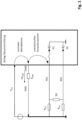
- Figure 1 shows a relevant state of the art. Due to the ground resistance (R GND ), the ground offset is dropped as a voltage ( ⁇ V GND ) across the ground resistance (R GND ) of the ground lead of the airbag control device.
- the airbag control device controls the squib (SQ) of the airbag via a first control line (AS1) and a second control line (AS2). If, for example, in the event of an accident, a low-resistance short circuit occurs between the first control line (AS1) and the vehicle ground (GND), the supply voltage (V bat ) feeds a current into the airbag control device.
- the internal ground (GNDi) of the control device is at a potential that is the ground offset ( ⁇ V GND ) above the potential of the vehicle ground (GND).
- the supply voltage (V bat ) therefore also feeds a current into the safety-relevant control device (ECU).
- This injected current flows through the control line (AS1, AS2) short-circuited with the vehicle ground (GND) to the vehicle ground.
- this current is fed by the supply voltage line (V bat ) into the substrate of the control device, where it can cause effects that are difficult to predict.
- such injected currents can switch parasitic bipolar transistors.
- the first diode (D1) and the second diode (D2) are intended to symbolize ESD protection structures.
- Figure 2 corresponds to the Figure 1 with the difference that the third diode (D3) and the fourth diode (D4) now take over the current when the voltage difference between the internal ground (GNDi) and the vehicle ground (GND) is greater than the threshold voltage of these diodes.
- Figure 2 is state of the art.
- Figure 3 is intended to illustrate the state of the method according to the invention in the second operating state in a schematic and simplified manner.
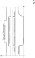
- FIG. 4 shows the time sequence in principle and in a roughly simplified manner.
- the control device changes from the first operating state with a higher energy consumption to the second operating state with a lower energy consumption.
- the energy reserve (C) supplies the control device with energy and as a result the battery current drops.
- the control device then carries out the ignition or diagnostic event.
- the airbag control device ignites the ignition pills for which such a Ignition was intended.
- the control device could also carry out a test in this second operating state, in other words carry out a diagnostic event.
- the control device After the second operating state has ended, the control device returns to the first operating state.
- the battery current from the operating voltage source via the supply voltage line (V bat ) increases again.
- the current in the supply voltage line (V bat ) is higher at this time than before the energy reserve (C) was used.
- the supply voltage (V bat ) then recharges the energy reserve (C), which is typically a capacitor. This requires an additional charging current for the duration of the temporal charging phase.
- FIG 5 shows a proposed device that carries out the proposed method.
- the device comprises a voltage source (V batsup) of the vehicle.
- the voltage source (V batsup ) of the vehicle generates the potential of the supply voltage (V bat ) compared to the potential of the vehicle ground (GND).
- the safety-relevant control device (ECU) comprises in the example of the Figure 5 as a further device, a charging circuit (ECUVC).
- the charging circuit takes electrical power from the supply voltage (V bat ) and the ground contact of the safety-relevant control device (ECU), which represents the internal ground of the safety-relevant control device (ECU).
- the charging circuit (ECUVC) charges the energy reserve (C) in the form of a capacitor, for example, to the potential of an internal supply voltage (V bati ).
- the charging circuit (ECUVC) also supplies the control circuit (ECUIC) of the safety-relevant control device (ECU) with electrical energy via the internal supply voltage (V bati ).
- the safety-relevant control circuit (ECUIC) and the charging circuit (ECHVC) can be manufactured as a single piece, monolithically integrated on a semiconductor crystal.
- the safety-relevant control circuit (ECUIC) of the safety-relevant control device (ECU) can switch the charging circuit from the first operating state to a second operating state via a shutdown line (ECUVCL).
- the charging circuit (ECUVC) does not charge the energy reserve (C) in the form of a capacitor.
- the charging circuit (ECUVC) supplies the control circuit (ECUIC) of the safety-relevant control device (ECU) with electrical energy.
- the energy reserve (C) supplies the safety-relevant control circuit (ECUIC) of the safety-relevant control device (ECU) and, if applicable, other sub-devices of the safety-relevant control device (ECU) with electrical energy.
- the current consumption of the charging circuit (ECUIC) and thus of the safety-relevant control device (ECU) is therefore reduced in the second operating state.
- the internal ground point (GNDi) of the safety-relevant control device (ECU) is connected to the vehicle ground (GND) via the parasitic ground resistance (R GND ). This parasitic ground resistance (R GND ) is typically often around 2 Ohm.
- the ground offset has a ground offset voltage ( ⁇ V GND ).
- ⁇ V GND ground offset voltage
- the ground offset can then be different from 0V. This ground offset can therefore lead to the problems described above in the event of a short circuit (SC1, SC2) between a connection line of the safety-relevant control device (ECU) and the vehicle ground (GND).
- the Figure 5 shows an example of an airbag control device as a safety-relevant control device (ECU).
- the safety-relevant control device (ECU) is connected to several ignition caps via connecting lines.
- one ignition cap (SQ) of the ignition caps is connected to the safety-relevant control device (ECU) with a first connecting line (AS1) and a second connecting line (AS2).
- the safety-relevant control device (ECU) evaluates signals from sensors (SO).
- an exemplary sensor (SO) is connected to the safety-relevant control circuit (ECUIC) of the safety-relevant control device (ECU) via a sensor line (SOL).
- the safety-relevant control device (ECU) now implements the safety-relevant function in such a way that it detects a safety-relevant incident, for example an accident, with the help of one or more sensors (SO).
- the safety-relevant control device (ECU) preferably communicates with the sensors via the sensor lines (SOL).
- the sensor lines can be a PSl5 data bus or a DSI3 data bus or the like.
- ECU safety-relevant control circuit
- the safety-relevant control circuit (ECUIC) of the safety-relevant control device (ECU) detects such a safety-relevant incident, for example an accident, the safety-relevant control device (ECUIC) carries out its safety-relevant function.
- This is the ignition of the squib (SQ) to deploy the airbags of the exemplary airbag system.
- a first short circuit (SC1) can occur between the first connection line (AS1) of the ignition cap (SQ) and the vehicle ground (GND).
- a second short circuit (SC2) can also occur between the second connection line (AS2) of the ignition cap (SQ) and the vehicle ground (GND).
- a third short circuit can occur between the sensor connection line (SOL) of a sensor (SO) and the vehicle ground (GND).
- SOL sensor connection line
- GND vehicle ground
- other short circuits between connections of the safety-relevant control device (ECU) and the vehicle ground (GND) can also occur, which can have a similar destructive effect.
- the short circuits (SC1, SC2, SC3) in the Figure 5 are therefore only examples.
- the safety-relevant control device (ECU) or another higher-level device tries to minimize the power consumption of the devices whose operating current is diverted to the vehicle ground via the same ground line.
Landscapes
- Engineering & Computer Science (AREA)
- Mechanical Engineering (AREA)
- Air Bags (AREA)
Description
Verfahren zum Betrieb einer sicherheitsrelevanten Steuervorrichtung für Fahrzeuge, insbesondere für eine Airbag-Steuervorrichtung.Method for operating a safety-relevant control device for vehicles, in particular for an airbag control device.
Die hier vorgelegte Schrift erläutert die Probleme des Stands der Technik anhand der
Sicherheitsrelevante Applikationen wie ein Airbag-Steuergerät weisen die Notwendigkeit auf, auch bei Vorliegen äußerer Fehlereinflüsse z.B. im Zusammenhang mit Unfällen möglichst ausfallsicher funktionieren zu müssen. Solche Ausfälle äußerer Fehlereinflüsse können beispielsweise Kurzschlüsse und Unterbrechungen im Kabelbaum sein. Die modernen Airbag-Steuergeräte umfassen heute typischerweise integrierte Schaltungen, bei denen bevorzugt eine integrierte Schaltung mehrere Zündpillen der Airbags zündet. Dabei ist je Zündpille typischerweise ein Zündkreis vorgesehen, mittels dessen die betreffende integrierte Schaltung innerhalb des Airbag-Steuergeräts die Zündpille im Falle eines Unfalls zündet und für eine Entfaltung des Airbags sorgt. Ein Kurzschluss an einer Zuleitung einer Zündpille gegen die Fahrzeugmasse darf dabei die Zündung der anderen Zündpillen der anderen Zündkreise nicht verhindern oder beeinträchtigen.Safety-relevant applications such as an airbag control unit must function as reliably as possible even in the event of external faults, e.g. in connection with accidents. Such failures due to external faults can be, for example, short circuits and interruptions in the wiring harness. Modern airbag control units typically include integrated circuits in which one integrated circuit preferably ignites several airbag squibs. Typically, one ignition circuit is provided for each squib, by means of which the relevant integrated circuit within the airbag control unit ignites the squib in the event of an accident and ensures that the airbag is deployed. A short circuit on a squib lead to the vehicle ground must not prevent or impair the ignition of the other squibs in the other ignition circuits.
Im Falle eines Unfalls können jedoch durchaus ein oder mehrere Zuleitungen der Zündpillen eines Airbag-Zündsystems in Folge der hohen unvorhersehbaren mechanischen Einwirkungen in Kontakt mit elektrisch leitenden Teilen der Karosserie geraten. Hierdurch können sehr niederohmige Kurzschlüsse einer Zuleitung einer Zündpille gegen die Fahrzeugmasse entstehen. Weist nun die Massezuleitung des Airbag-Steuergeräts einen größeren Zuleitungswiderstand auf, so kann über diesen Zuleitungswiderstand eine Spannung gegenüber der echten Fahrzeugmasse abfallen. In Folge dessen befindet sich dann der Masse-Anschluss des Airbag-Steuergeräts (GNDi) auf einem höheren elektrischen Potenzial als der gegen die Fahrzeugmasse kurzgeschlossene Anschluss der Zündpille.In the event of an accident, however, one or more of the supply lines of the squibs of an airbag ignition system may come into contact with electrically conductive parts of the bodywork as a result of the high, unpredictable mechanical impacts. This can cause very low-resistance short circuits between a supply line of a squib and the vehicle ground. If the ground supply line of the airbag control unit has a higher supply line resistance, a voltage drop compared to the actual vehicle ground can occur across this supply line resistance. As a result, the ground connection of the airbag control unit (GNDi) is then at a higher electrical potential than the connection of the squib that is short-circuited to the vehicle ground.
Dies führt in der Konsequenz zu einem ungewollten Stromfluss von der Massezuleitung des Airbag-Steuergeräts (GNDi) über die ESD-Dioden oder parasitären Dioden D1 und D2 zu dem kurzgeschlossenen Anschluss der Zündpille. Diese Kurzschlüsse treten also primär an den Treiberleitungen der Zündpille auf.This results in an unwanted current flow from the ground line of the airbag control unit (GNDi) via the ESD diodes or parasitic diodes D1 and D2 to the short-circuited connection of the squib. These short circuits therefore primarily occur on the driver lines of the squib.
Ein solcher, ungewollter Stromfluss kann zu einer nicht zulässigen Beeinträchtigung sicherheitsrelevanter Funktionalitäten führen. Eine aus dem Stand der Technik bekannte Lösung ist die Verwendung von Dioden. Diese Dioden verbinden einen gegen die Fahrzeugmasse kurzgeschlossenen Anschluss der Zündpille mit dem Masse-Anschluss des Airbag-Steuergeräts, wenn die Spannungsdifferenz zwischen der Fahrzeugmasse und dem Potenzial Masse-Anschluss des Airbag-Steuergeräts größer ist als die Schleusenspannung der betreffenden Diode. Diese Dioden verbinden einen gegen die Fahrzeugmasse kurzgeschlossenen Anschluss der Zündpille mit dem Masse-Anschluss des Airbag-Steuergeräts also dann, wenn die Fahrzeugmasse also um mehr als die Schleusenspannung der Diode unter dem Potenzial des Masse-Anschlusses des Airbag-Steuergeräts liegt. Diese Dioden D3, D4 können die dann entstehenden Ausgleichströme an dem relevanten Anschluss der Zündpille vorbeiführen. Dies ist in
Das sicherheitsrelevante Airbag-Steuergerät soll insbesondere diagnostizierbar bzw. zündfähig hinsichtlich der Squib-Treibladungen bleiben, sofern Fehlereinflüsse wie oben angedeutet auftreten, bei denen gleichzeitig sowohl von Kurzschlüssen zur Fahrzeugmasse, als auch von einem erhöhten GND Widerstand ausgegangen werden muss.The safety-relevant airbag control unit should in particular remain diagnosable and capable of igniting the squib propellant charges if fault influences such as those indicated above occur, where both short circuits to the vehicle ground and an increased GND resistance must be assumed.
Die kurzgeschlossenen Anschlüsse der Zündpille führen dann in diesem Fehlerfall durch das über den Massewiderstand ansteigende Massepotential des Masseanschlusses des Airbag-Steuergeräts den Massestrom potentiell über zumindest in Teilen in die Fahrzeugmasse hinein ab. Dies führt zu einer Substratstrominjektion in der betreffenden integrierten Schaltung des Airbag-Steuergeräts mit dem hohen Potenzial, Folgefehler zu generieren.In this case of error, the short-circuited connections of the squib then potentially conduct the ground current, at least in part, into the vehicle ground due to the ground potential of the ground connection of the airbag control unit rising above the ground resistance. This leads to a substrate current injection in the relevant integrated circuit of the airbag control unit with the high potential of generating subsequent errors.
Im Rahmen von Recherchen zum Artikel vom 29.04.2019 wurde offenbar, dass auch bei bestehenden Applikationen im automobilen Umfeld mutmaßlich in ähnlicher Art und Weise ein auftretender EOS die angeforderten, beabsichtigten Zündvorgänge im Falle eines ungünstig verlaufenden Unfalls unterbinden kann.During research into the article from April 29, 2019, it became apparent that in existing applications in the automotive environment, an EOS can presumably prevent the requested, intended ignition processes in the event of an unfavorable accident in a similar way.
(Quelle: https://www.pcwelt.de/news/Riesen-Rueckruf-droht-Ueber-12-Millionen-Airbags-koennten-versagen-10581707.html)(Source: https://www.pcwelt.de/news/Riesen-Rueckruf-droht-Ueber-12-million-Airbags-koennten-fallen-10581707.html)
Beispielhafte Airbag-Schaltungen aus dem Stand der Technik sind die
Die Aufgabe, die dem Vorschlag zugrunde liegt, ist es daher, eine Lösung zu schaffen, die die obigen Nachteile des Stands der Technik nicht aufweist und weitere Vorteile aufweist.The task underlying the proposal is therefore to create a solution which does not have the above disadvantages of the prior art and has further advantages.
Im Applikationsumfeld von Airbags soll im Falle von Masseversatz kein Substratstrom und damit keine negative Beeinflussung sicherheitsrelevanter Funktionen auftreten.In the application environment of airbags, no substrate current should occur in the event of mass offset and thus no negative influence on safety-relevant functions.
Verfahren nach den unabhängigen Ansprüchen lösen diese Aufgabe. Weitere Ausgestaltungen sind Gegenstand von Unteransprüchen.Methods according to the independent claims solve this problem. Further embodiments are the subject of subclaims.
Sicherheitsrelevante Systeme wie z.B. Airbag-Steuergeräte weisen bevorzugt Energiespeicher auf. Diese Energiespeicher dienen zur zumindest zeitweisen energetischen Selbstversorgung. Diese Selbstversorgung ist notwendig im Falle einer Unterbrechung der Energieversorgung in Zusammenhang mit einem Unfall. Airbag-Steuergeräte können bevorzugt diesen Betriebszustand einer energetischen Notversorgung aus der Energiereserve aktiv forcieren.Safety-relevant systems such as airbag control units preferably have energy storage devices. These energy storage devices serve to provide at least temporary energy self-sufficiency. This self-sufficiency is necessary in the event of an interruption in the energy supply in connection with an accident. Airbag control units can preferably actively force this operating state of an emergency energy supply from the energy reserve.
Die kostengünstigere Alternative im Vergleich zur Lösung der
Die Energieversorgung der Vorrichtung kann den Autarky-Betrieb kann über den typischerweise für Airbag-Steuergeräte verfügbaren Betriebsmodus mittels Selbstversorgung (auch Autarky genannt) aus der besagten Energiereserve erreichen. Diese besteht in der Regel aus entsprechenden Kondensatoren entsprechender Kapazität. Ein Konstrukteur legt bevorzugt diese Kapazität typischerweise für die Zündvorgänge nach Wegfall der Batterieversorgung des Fahrzeugs aus. Potentiell kann der Fachmann diese Methode auf alle Systeme mit zumindest zeitweise verfügbarer Selbstversorgung anwenden.The power supply of the device can achieve self-sufficient operation via the operating mode typically available for airbag control units by means of self-supply (also called self-sufficient) from the energy reserve mentioned. This usually consists of corresponding capacitors of corresponding capacity. A designer typically prefers to design this capacity for the ignition processes after the vehicle's battery supply is lost. Potentially, the expert can apply this method to all systems with at least temporary self-sufficiency.
Die Erfindung betrifft somit Verfahren zum Betrieb einer sicherheitsrelevanten Steuervorrichtung für Fahrzeuge, insbesondere für eine Airbag-Steuervorrichtung. Dabei weist die Steuervorrichtung eine Energiereserve auf. Das Fahrzeug weist typischerweise ein elektrisches Bordnetz mit Versorgungsspannungsleitungen auf. Die Steuervorrichtung empfängt Signale von Sensoren und/oder anderen Systemen. Die sicherheitsrelevante Steuervorrichtung weist einen ersten Betriebszustand und einen zweiten Betriebszustand auf. Dabei ist bevorzugt die Energieaufnahme der sicherheitsrelevanten Steuervorrichtung im ersten Betriebszustand betragsmäßig kleiner als im zweiten Betriebszustand. Dennoch kann bevorzugt im ersten und zweiten Betriebszustand die sicherheitsrelevante Steuervorrichtung ihre sicherheitsrelevante Funktion ausüben.The invention thus relates to methods for operating a safety-relevant control device for vehicles, in particular for an airbag control device. The control device has an energy reserve. The vehicle typically has an electrical on-board network with supply voltage lines. The control device receives signals from sensors and/or other systems. The safety-relevant control device has a first operating state and a second operating state. The energy consumption of the safety-relevant control device is preferably smaller in the first operating state than in the second operating state. Nevertheless, the safety-relevant control device can preferably perform its safety-relevant function in the first and second operating states.
Das Verfahren umfasst bevorzugt den Schritt des Bereitstellens einer Energiereserve. Das Verfahren umfasst bevorzugt den Schritt des Auswertens der Signale der Sensoren und/oder der anderen Systeme. Das Verfahren umfasst bevorzugt den Schritt des Feststellens eines sicherheitsrelevanten Ereignisses in Abhängigkeit von den Signalen der Sensoren und/oder der anderen Systeme. Das Verfahren umfasst bevorzugt den Schritt des Umschaltens auf den zweiten Betriebszustand im Falle eines sicherheitsrelevanten Ereignisses. Das Verfahren umfasst bevorzugt den Schritt des Durchführens der sicherheitsrelevanten Funktion der sicherheitsrelevanten Steuervorrichtung im zweiten Betriebszustand.The method preferably comprises the step of providing an energy reserve. The method preferably comprises the step of evaluating the signals from the sensors and/or the other systems. The method preferably comprises the step of determining a safety-relevant event depending on the signals from the sensors and/or the other systems. The method preferably comprises the step of switching to the second operating state in the event of a safety-relevant event. The method preferably comprises the step of carrying out the safety-relevant function of the safety-relevant control device in the second operating state.
Das Verfahren ist gekennzeichnet durch den Schritt der Versorgung der sicherheitsrelevanten Steuervorrichtung aus der Energiereserve, wenn die sicherheitsrelevante Steuervorrichtung sich im zweiten Betriebszustand befindet. Um jede Art von Störung über das Bordnetz während eines Unfalls auszuschließen erfolgt das Versorgen der sicherheitsrelevanten Steuervorrichtung nur im ersten Betriebszustand aus dem elektrischen Bordnetz des Fahrzeugs mittels der Versorgungsspannungsleitungen mit elektrischer Energie. Aus dem gleichen Grund erfolgt das Laden der Energiereserve nur im ersten Betriebszustand aus dem elektrischen Bordnetz des Fahrzeugs mittels der Versorgungsspannungsleitungen mit elektrischer Energie. Sofern es nun zu einem Unfall kommt erfolgt möglichst sofort nach der Feststellung des sicherheitsrelevanten Ereignisses ein Trennen der sicherheitsrelevanten Steuervorrichtung im zweiten Betriebszustand von dem elektrischen Bordnetz des Fahrzeugs und den Versorgungsspannungsleitungen mittels einer Trennvorrichtung. Diese Trennung sollte bevorzugt unabhängig von der Spannungsdifferenz zwischen dem Potenzial der betreffenden Versorgungsspannungsleitungen einerseits und dem Potenzial eines Bezugspotenzialknotens des sicherheitsrelevanten Steuergeräts andererseits erfolgen. Dies stellt sicher, dass keine Energie aus der Energiereserve in das Boardnetz abfließt. Daher erfolgt bevorzugt auch ein Trennen der Energiereserve im zweiten Betriebszustand von dem elektrischen Bordnetz des Fahrzeugs und den Versorgungsspannungsleitungen mittels einer Trennvorrichtung. Diese Trennung bedeutet, dass ein ggf. noch fließender Reststrom die Funktion der sicherheitsrelevanten Vorrichtung nicht mehr beeinträchtigen kann. Diese Trennung der Energiereserve vom Bordnetz erfolgt natürlich bevorzugt ebenfalls unabhängig von der Spannungsdifferenz zwischen dem Potenzial der betreffenden Versorgungsspannungsleitungen einerseits und dem Potenzial eines Bezugspotenzialknotens des Sicherheitsrelevanten Steuergeräts andererseits. Bevorzugt verwendet das vorgeschlagene Verfahren für beide Trennungen die gleiche Trennvorrichtung. Hierbei kann es sich um Transistoren oder andere elektrische Schalter handeln. Bevorzugt betätigt die sicherheitsrelevante Steuervorrichtung diese Trennvorrichtungen, wenn diese einer Betätigung bedürfen.The method is characterized by the step of supplying the safety-relevant control device from the energy reserve when the safety-relevant control device is in the second operating state. In order to exclude any type of interference via the on-board network during an accident, the safety-relevant control device is only supplied with electrical energy in the first operating state from the vehicle's electrical on-board network using the supply voltage lines. For the same reason, the energy reserve is only charged with electrical energy in the first operating state from the vehicle's electrical on-board network using the supply voltage lines. If an accident occurs, the safety-relevant control device in the second operating state is separated from the vehicle's electrical on-board network and the supply voltage lines using a separating device as soon as possible after the safety-relevant event has been detected. This separation should preferably take place independently of the voltage difference between the potential of the relevant supply voltage lines on the one hand and the potential of a reference potential node of the safety-relevant control device on the other. This represents ensure that no energy flows from the energy reserve into the on-board network. Therefore, in the second operating state, the energy reserve is preferably also separated from the vehicle's electrical system and the supply voltage lines by means of a separating device. This separation means that any residual current that may still be flowing can no longer impair the function of the safety-relevant device. This separation of the energy reserve from the on-board network is of course preferably also carried out independently of the voltage difference between the potential of the relevant supply voltage lines on the one hand and the potential of a reference potential node of the safety-relevant control unit on the other. The proposed method preferably uses the same separating device for both separations. These can be transistors or other electrical switches. The safety-relevant control device preferably actuates these separating devices when they require actuation.
Das Verfahrensprinzip lässt sich auch auf die Durchführung sicherheitsrelevanter Tests anwenden. Es handelt sich dann um ein Verfahren zum Betrieb einer sicherheitsrelevanten Steuervorrichtung für Fahrzeuge, insbesondere für eine Airbag-Steuervorrichtung, wobei die Steuervorrichtung eine Energiereserve aufweist, wobei die sicherheitsrelevante Steuervorrichtung einen ersten Betriebszustand und einen zweiten Betriebszustand aufweist. Die Energieaufnahme aus der Batterie der sicherheitsrelevanten Steuervorrichtung ist bevorzugt im ersten Betriebszustand betragsmäßig höher als im zweiten Betriebszustand. Im ersten und zweiten Betriebszustand kann die sicherheitsrelevante Steuervorrichtung ihre sicherheitsrelevante Funktion ausüben, wobei die hier vorgelegte Schrift die Durchführung von sicherheitsrelevanten Tests hier als Durchführung einer sicherheitsrelevanten Funktion versteht. Das Verfahren umfasst in diesem Fall des sicherheitsrelevanten Tests dann die Schritte des Bereitstellens einer Energiereserve, des Feststellens der Notwendigkeit eines sicherheitsrelevanten Tests, des Umschaltens auf den zweiten Betriebszustand, des Durchführens des sicherheitsrelevanten Tests durch die sicherheitsrelevante Steuervorrichtung im zweiten Betriebszustand und des Zurückschaltens auf den ersten Betriebszustand. Das Verfahren zeichnet sich dabei durch den Schritt der Versorgung der sicherheitsrelevanten Steuervorrichtung aus der Energiereserve aus, wenn die sicherheitsrelevante Steuervorrichtung sich im zweiten Betriebszustand befindet. Eine Zeitscheibensteuerung oder ein Zeitgeber oder eine andere Vorrichtung können die Notwendigkeit eines sicherheitsrelevanten Tests beispielsweise feststellen.The principle of the method can also be applied to the performance of safety-relevant tests. This is then a method for operating a safety-relevant control device for vehicles, in particular for an airbag control device, wherein the control device has an energy reserve, wherein the safety-relevant control device has a first operating state and a second operating state. The energy consumption from the battery of the safety-relevant control device is preferably higher in the first operating state than in the second operating state. In the first and second operating states, the safety-relevant control device can perform its safety-relevant function, wherein the document presented here understands the performance of safety-relevant tests here as the performance of a safety-relevant function. In this case of the safety-relevant test, the method then comprises the steps of providing an energy reserve, determining the need for a safety-relevant test, switching to the second operating state, performing the safety-relevant test by the safety-relevant control device in the second operating state and switching back to the first operating state. The method is characterized by the step of supplying the safety-relevant control device from the energy reserve when the safety-relevant control device is in the second operating state. A time slice control or a timer or another device can, for example, determine the need for a safety-relevant test.
Dieser Grundgedanke lässt sich noch erweitern. Die Ausarbeitung des hier vorgelegten Vorschlags führte zu der Erkenntnis, dass auch andere Systemkomponenten eines Fahrzeugs den Masseversatz der sicherheitsrelevanten Steuerung beeinflussen können.This basic idea can be expanded even further. The development of the proposal presented here led to the realization that other system components of a vehicle can also influence the mass offset of the safety-relevant control system.
Basierend auf den zuvor beschriebenen Verfahren ist daher ein Verfahren zum Betrieb einer sicherheitsrelevanten Steuervorrichtung denkbar, bei dem die sicherheitsrelevante Steuervorrichtung eine Verbindung zu mindestens einer weiteren Systemkomponente des Fahrzeugs aufweist. Solche weiteren Systemkomponenten können beispielsweise, aber nicht nur, Sitzheizungen oder Stellmotoren oder ähnliches sein, die die Vorrichtung nicht in Bezug auf die Sicherheitsfunktion benötigt und auf deren Funktion die Vorrichtung zumindest zeitweise oder speziell im Falle eines Unfalls verzichten kann. Die besagte Verbindung zwischen der sicherheitsrelevanten Steuervorrichtung und der weiteren Systemkomponente kann eine analoge oder digitale direkte Punkt-zu-Punkt-Verbindung zwischen der sicherheitsrelevanten Steuervorrichtung und der weiteren Systemkomponente sein. Ein gemeinsamer Datenbus oder dergleichen kann eine solche Verbindung auch herstellen. Es ist aber auch denkbar, dass eine übergeordnete Rechnereinheit die Verbindung zwischen der sicherheitsrelevanten Steuervorrichtung und der weiteren Systemkomponente herstellt, die mit einem ersten Datenbus verbunden ist und mit einem zweiten, davon getrennten Datenbus verbunden ist. Die sicherheitsrelevante Steuervorrichtung ist dann beispielsweise mit dem ersten Datenbus verbunden und die weitere Systemkomponente mit dem zweiten Datenbus. Somit kann dann die sicherheitsrelevante Steuervorrichtung nur indirekt über die übergeordnete Rechnereinheit mit der weiteren Systemkomponente kommunizieren. Das Problem tritt nun dadurch auf, dass die sicherheitsrelevante Steuervorrichtung einen Masseanschluss aufweist, die weitere Systemkomponente einen ersten Betriebszustand und einen zweiten Betriebszustand aufweist und dass die Energieaufnahme dieser weiteren Systemkomponente im ersten Betriebszustand betragsmäßig höher ist als im zweiten Betriebszustand. Hierdurch kommt es beim Betrieb der weiteren Systemkomponente im ersten Betriebszustand der weiteren Systemkomponente zu einem ersten zusätzlichen Masseversatz des Potenzials des Masseanschlusses der sicherheitsrelevanten Steuervorrichtung gegenüber einem Referenzpotenzial, Des Weiteren kommt es beim Betrieb der weiteren Systemkomponente im zweiten Betriebszustand der weiteren Systemkomponente zu einem zweiten zusätzlichen Masseversatz des Potenzials des Masseanschlusses der sicherheitsrelevanten Steuervorrichtung gegenüber einem Referenzpotenzial. Der hier vorgelegte Text nimmt beispielhaft an, dass der zweite Masseversatz auch 0V betragen kann. Beispielhaft nehmen wir also an, dass der Betrag des ersten Masseversatzes größer ist als der Betrag des zweiten Masseversatzes. Dieser zusätzliche Masseversatz kann das zuvor beschriebene Problem verschärfen. Der hier vorgelegte Text schlägt nun vor, dass zur Verminderung der Auswirkungen des Masseversatzes die sicherheitsrelevante Steuervorrichtung einen Wechsel des Betriebszustandes der weiteren Systemkomponente veranlassen kann. Das Fahrzeug kann also im Falle eines Unfalls in einen Unfall-Betriebszustand schalten, in dem die sicherheitsrelevante Steuervorrichtung oder eine übergeordnete Vorrichtung alle unnötigen Verbraucher u.a. zur Verminderung der Masseversätze abschalten. Es kann aber auch vorteilhaft sein, weniger wichtige Systemkomponenten im Normalbetrieb für die Durchführung sicherheitsrelevanter Tests vorübergehend in einen stromsparenden Betriebszustand zu versetzen.Based on the methods described above, a method for operating a safety-relevant control device is therefore conceivable in which the safety-relevant control device has a connection to at least one further system component of the vehicle. Such further system components can be, for example, but not only, seat heaters or servomotors or similar, which the device does not need in relation to the safety function and whose function the device can dispense with at least temporarily or specifically in the event of an accident. The said connection between the safety-relevant control device and the further system component can be an analog or digital direct point-to-point connection between the safety-relevant control device and the further system component. A common data bus or the like can also establish such a connection. However, it is also conceivable for a higher-level computer unit to establish the connection between the safety-relevant control device and the further system component, which is connected to a first data bus and to a second, separate data bus. The safety-relevant control device is then connected, for example, to the first data bus and the further system component to the second data bus. The safety-relevant control device can then only communicate indirectly with the other system component via the higher-level computer unit. The problem now arises because the safety-relevant control device has a ground connection, the other system component has a first operating state and a second operating state, and the energy consumption of this other system component is higher in the first operating state than in the second operating state. As a result, when the other system component is operating in the first operating state of the other system component, there is a first additional ground offset of the potential of the ground connection of the safety-relevant control device compared to a reference potential. Furthermore, when the other system component is operating in the second operating state of the other system component, there is a second additional ground offset of the potential of the ground connection of the safety-relevant control device compared to a reference potential. The text presented here assumes, for example, that the second ground offset can also be 0V. For example, we assume that the amount of the first ground offset is greater than the amount of the second ground offset. This additional ground offset can exacerbate the problem described above. The text presented here now proposes that in order to reduce the impact of the In the event of an accident, the safety-relevant control device can cause the operating state of the other system components to change. In the event of an accident, the vehicle can therefore switch to an accident operating state in which the safety-relevant control device or a higher-level device switches off all unnecessary consumers, among other things to reduce the mass offsets. However, it can also be advantageous to temporarily switch less important system components to a power-saving operating state during normal operation in order to carry out safety-relevant tests.
Ein solches Verfahren umfasst dann bevorzugt den Schritt des Feststellens der Notwendigkeit eines sicherheitsrelevanten Tests durch die sicherheitsrelevante Steuervorrichtung. Des Weiteren umfasst ein solches Verfahren dann bevorzugt den Schritt des Umschaltens der weiteren Systemkomponente auf den zweiten Betriebszustand der weiteren Systemkomponente. Außerdem umfasst ein solches Verfahren dann bevorzugt den Schritt des Durchführens des sicherheitsrelevanten Tests durch die sicherheitsrelevante Steuervorrichtung. Die weitere Systemkomponente befindet sich dabei während des sicherheitsrelevanten Tests im zweiten Betriebszustand der weiteren Systemkomponente. Schließlich umfasst ein solches Verfahren dann bevorzugt den Schritt des Beendens des sicherheitsrelevanten Tests und Zurückschalten der weiteren Systemkomponente auf den ersten Betriebszustand der weiteren Systemkomponente.Such a method then preferably includes the step of determining the need for a safety-relevant test by the safety-relevant control device. Furthermore, such a method then preferably includes the step of switching the further system component to the second operating state of the further system component. Furthermore, such a method then preferably includes the step of carrying out the safety-relevant test by the safety-relevant control device. The further system component is in the second operating state of the further system component during the safety-relevant test. Finally, such a method then preferably includes the step of ending the safety-relevant test and switching the further system component back to the first operating state of the further system component.
Wie bereits erwähnt, kann eine übergeordnete Steuereinheit eine indirekte Verbindung der sicherheitsrelevanten Steuervorrichtung mit weiteren Systemkomponenten bereitstellen und darstellen.As already mentioned, a higher-level control unit can provide and represent an indirect connection of the safety-relevant control device with other system components.
Im Folgenden stellt die hier vorgelegte Schrift nun verschiedene, sehr ähnliche Verfahren und deren Varianten vor deren Merkmale ein Anwender der technischen Lehre dieser Schrift bei Sinnhaftigkeit miteinander ausdrücklich kombinieren kann. Die Kombinationen - soweit sinnvoll - sind also ausdrücklich Teil der Offenlegung dieser Schrift, auch wenn verschiedene Merkmale in unterschiedlichen Verfahrensvarianten Erwähnung finden. Ein Beispiel wäre hier z.B. eine Trennvorrichtung, die im Folgenden eine Variante erwähnt, die aber ein Anwender in allen Verfahrensvarianten als Mittel zur Stromaufnahmereduktion einsetzten kann.In the following, the document presented here now presents various, very similar processes and their variants, the features of which a user of the technical teaching of this document can expressly combine with one another if it makes sense. The combinations - if it makes sense - are therefore expressly part of the disclosure of this document, even if different features are mentioned in different process variants. An example here would be a separating device, which mentions one variant below, but which a user can use in all process variants as a means of reducing power consumption.
Der hier vorgelegte Vorschlag betrifft somit ein Verfahren zum Betrieb einer sicherheitsrelevanten Steuervorrichtung für Fahrzeuge, insbesondere für eine Airbag-Steuervorrichtung in einem Fahrzeug. Das Fahrzeug weist bevorzugt eine weitere Vorrichtung (ECUVC) auf, bei der es sich bevorzugt um eine Ladeschaltung (ECHVC) für die Energiereserve (C) der sicherheitsrelevanten Steuervorrichtung (ECU) handelt. Typischerweise versorgt diese Ladeschaltung (ECUVC) die Steuerschaltung (ECUIC) der sicherheitsrelevanten Steuervorrichtung (ECU) und ggf. andere Vorrichtungsteile der sicherheitsrelevanten Steuervorrichtung (ECU) im ersten Betriebszustand der sicherheitsrelevanten Steuervorrichtung (ECU), also im Normalbetrieb, mit elektrischer Energie. Die Steuervorrichtung (ECU) weist einen internen Massekontakt (GNDi) auf. Das Fahrzeug weist einen anderen Massepunkt (GND), typischerweise die Karosserie des Fahrzeugs als Fahrzeugmasse, auf. Die Steuervorrichtung umfasst die bereits erwähnte Energiereserve (C). Die weitere Vorrichtung kann Teil der Sicherheitsrelevanten Steuervorrichtung (ECU) sein. Beispielsweise kann es sich bei der weiteren Vorrichtung um die Ladeschaltung (ECUVC) der sicherheitsrelevanten Vorrichtung (ECU) handeln. Es kann sich aber auch bei der weiteren Vorrichtung um eine Vorrichtung des Fahrzeugs handeln, die nicht Teil der sicherheitsrelevanten Steuervorrichtung (ECU) ist. Eine solche weitere Vorrichtung kann beispielsweise eine Sitzheizung oder dergleichen sein. Die Stromaufnahme dieser für das hier diskutierte Problem relevanten, weiteren Vorrichtung trägt in einem aktiven Betriebszustand zu einer Vergrößerung des Betrags der Masseversatzspannung (ΔVGND) bei. Die die hier vorgestellte sicherheitsrelevante Steuervorrichtung (ECU) oder eine andere Vorrichtung des Fahrzeugs schalten daher diese weitere Vorrichtung bei einem sicherheitsrelevanten Vorfall ab, sodass die weitere Vorrichtung keinen Strom mehr in die mit der sicherheitsrelevanten Steuervorrichtung gemeinsame Masseleitung einspeist oder nur noch einen wesentlich geringeren Strom in diese Masseleitung einspeist. Die weitere Vorrichtung weist somit im Normalbetrieb eine Stromaufnahme eines elektrischen Stromes zu ihrem Betrieb auf. Dieser elektrische Strom der weiteren Vorrichtung kann zu einem Masseversatz mit einer von 0V verschiedenen Masseversatzspannung (ΔVGND) führen. Diese Masseversatzspannung (ΔVGND) entsteht dabei zwischen dem internen Massekontakt (GNDi) der sicherheitsrelevanten Steuervorrichtung (ECU) einerseits und dem anderen Massepunkt (GND) des Fahrzeugs andererseits. Der andere Massepunkt (GND) kann beispielsweise die Karosserie als Fahrzeugmasse sein. Bei einem Kurzschluss zwischen einer anderen Leitung der sicherheitsrelevanten Steuervorrichtung (ECU) einerseits und diesem anderen Massepunkt (GND) des Fahrzeugs andererseits kann die betreffende kurzgeschlossene Leitung unter das Potenzial des internen Massekontakts (GNDi) des sicherheitsrelevanten Steuergeräts (ECU) geraten. Eine solche andere Leitung der sicherheitsrelevanten Steuervorrichtung (ECU) kann beispielsweise eine Zuleitung eines Sensors der sicherheitsrelevanten Steuervorrichtung (ECU) oder eine Zündleitung (AS1, AS2) einer Zündpille (SQ) eines Airbags sein. Der zuletzt genannte Fall bezieht sich dabei auf den Fall eines Airbag-Steuersystems als sicherheitsrelevanter Steuervorrichtung (ECU). In dem Fall würde dieser Kurzschluss ggf. sehr große Ladeströme aus der Ladeschaltung (ECUVC) entnehmen und dann die sicherheitsrelevante Steuervorrichtung (ECU) beschädigen oder zerstören. In dem Fall könnte die Steuervorrichtung ihre sicherheitsrelevante Funktion nicht mehr ausüben. Wie bereits erwähnt, empfängt die Steuervorrichtung (ECU) Signale von Sensoren und/oder anderen Systemen des Fahrzeugs. Beispielsweise können Datenbusse diese Sensoren und/oder andere Systeme einerseits mit der sicherheitsrelevanten Steuervorrichtung (ECU) andererseits elektrisch und/oder informationstechnisch verbinden. Diese Verbindungen können drahtgebunden oder drahtlos sein. Sofern sie drahtgebunden sind, kommen beispielsweise Datenbus wie der CAN-Datenbus, der PSI5-Datenbus, der DSl3-Datenbus, der Lin-Datenbus PWM-Verbindungen, einfache digitale und analoge Leitungen und/oder Leitungsbündel und dergleichen in Frage. Es kann sich auch um optische Datenbusse über Lichtwellenleiter handeln. Sofern es sich um elektrische Datenbusse handelt, kann ein Kurzschluss zwischen einem solchen elektrischen Datenbus und einem anderen Massepunkt (GND) des Fahrzeugs zu einem ähnlichen Effekt führen. Ein solcher Kurzschluss kann beispielsweise der Kurzschluss eines elektrischen Datenbusses mit der Karosserie des Fahrzeugs sein. Dies kann dann den Effekt haben, dass dann das Potenzial der kurzgeschlossenen Datenleitung unter dem Potenzial des internen Massekontakts (GDi) der sicherheitsrelevanten Steuervorrichtung (ECU) liegt. Wie zuvor kann dann ohne weitere Maßnahmen ein ungehemmter Stromfluss über diese kurzgeschlossene Datenleitung zu dem anderen Massepunkt (GND) einsetzen, der die sicherheitsrelevante Steuervorrichtung in ihrer Funktion beeinträchtigen kann, die Ausübung der sicherheitsrelevanten Funktion durch die sicherheitsrelevante Vorrichtung (ECU) verhindern kann oder sogar die sicherheitsrelevante Vorrichtung beschädigen oder zerstören kann. Im Sinne dieser Schrift weist die sicherheitsrelevante Steuervorrichtung (ECU) einen ersten Betriebszustand für den Normalbetrieb und einen zweiten Betriebszustand für den Fall der Ausübung der sicherheitsrelevanten Funktion auf. Im Falle einer Airbag-Steuerungsvorrichtung (Airbag-Steuergeräts) als sicherheitsrelevante Steuerungsvorrichtung (ECU) ist der erste Betriebszustand der normale Betriebszustand ohne Unfall und der zweite Betriebszustand der Zustand, in dem die Airbag-Steuerungsvorrichtung (ECU) einen Unfall mittels ihrer Sensoren detektiert und Airbags zündet. Die hier vorgelegte Schrift schlägt nun zur Vermeidung der zuvor beschriebenen Probleme somit vor, dass die Energieaufnahme der sicherheitsrelevanten Steuervorrichtung (ECU) im ersten Betriebszustand betragsmäßig höher, nämlich normal, ist als im zweiten Betriebszustand. Dies hat den Vorteil, dass der Stromfluss über die elektrischen Versorgungsleitungen der sicherheitsrelevanten Steuervorrichtung (ECU) in Folge der verminderten Stromaufnahme minimiert ist. Dies reduziert den Masseversatz, in Form einer Masseversatzspannung (ΔVGND), die über den Massewiderstand RGND abfällt. Das wiederum reduziert den Strom, der über einen Kurzschluss (SC1, SC1) eines anderen Anschlusses der sicherheitsrelevanten Steuervorrichtung (ECU) zum den anderen Massepunkt (GND) des Fahrzeugs infolge dieses Kurzschlusses (SC1, SC2) abfließt. Dies wiederum verhindert oder vermindert den Einfluss dieses Kurzschlussstromes auf die Funktionstüchtigkeit der sicherheitsrelevanten Steuerungsvorrichtung (ECU). Insbesondere die im Folgenden noch weiter ausgeführten Maßnahmen betreffend die Ladeschaltung reduzieren den Kurzschlussstrom um typischerweise mehrere Größenordnungen. (z.B. vom A-Bereich in den mA-Bereich). Im ersten und zweiten Betriebszustand kann die sicherheitsrelevante Steuervorrichtung (ECU) ihre sicherheitsrelevante Funktion ausüben. Allerdings sollte die Steuervorrichtung vorzugsweise in den zweiten Betriebszustand wechseln, um die sicherheitsrelevanten Funktion auszuüben. Bevorzugt ist es daher so, dass die sicherheitsrelevante Vorrichtung sich im Normalbetrieb im ersten Betriebszustand und bei der Ausübung der sicherheitsrelevanten Funktion im zweiten Betriebszustand befindet. In dieser Schrift ist dies als "kann" Aussage beschrieben, da die sicherheitsrelevante Steuerungsvorrichtung (ECU) noch im ersten Betriebszustand mit der Ausübung der sicherheitsrelevanten Funktion beginnen kann, bevor sie vollständig den zweiten Betriebszustand eingenommen hat. Wie bereits erwähnt umfasst das Fahrzeug die besagte weitere Vorrichtung. Bevorzugt weist die die weitere Vorrichtung (ECUVC) eine erste Stromaufnahme auf, wenn sich die Steuervorrichtung (ECU) im ersten Betriebszustand befindet und eine zweite Stromaufnahme, wenn sich die sicherheitsrelevante Steuerungsvorrichtung (ECU) im zweiten Betriebszustand befindet. Das in dieser Schrift vorgestellte Verfahren umfasst typischerweise den Schritt des Bereitstellens einer Energiereserve (C). Hierzu stellt das Verfahren beispielsweise einen Kondensator (C) als Energiespeicherelement der sicherheitsrelevanten Steuervorrichtung (ECU) bereit und lädt bevorzugt diesen Kondensator (C) mittels einer Ladeschaltung (ECUVC) auf ein typischerweise vorgesehenes Energieniveau. Bevorzugt steuert eine Steuerschaltung (ECUIC) der sicherheitsrelevanten Steuervorrichtung (ECU) mittels einer Abschaltleitung und/oder weiterer Steuersignale den Ladevorgang der Energiereserve (C) durch die Ladeschaltung (ECUVC). Die sicherheitsrelevante Steuerschaltung (ECUIC) der sicherheitsrelevanten Steuervorrichtung (ECU) wertet typischerweise im Betrieb die Signale der Sensoren und/oder der anderen Systeme aus und schließt ggf. auf einen sicherheitsrelevanten Vorfall, beispielsweise einen Unfall. Bei einem solchen sicherheitsrelevanten Vorfall bringt die Steuerschaltung (ECUIC) der sicherheitsrelevanten Steuervorrichtung (ECU) typischerweise die sicherheitsrelevante Steuervorrichtung (ECU) von dem ersten Betriebszustand in den zweiten Betriebszustand und veranlasst die sicherheitsrelevante Steuervorrichtung (ECU) ihre sicherheitsrelevante Funktion, z.B. das Zünden von Airbags, auszuüben. Das in dieser Schrift vorgestellte Verfahren umfasst daher auch den Schritt des Feststellens eines sicherheitsrelevanten Ereignisses in Abhängigkeit von den Signalen der Sensoren und/oder der anderen Systeme und den Schritt des Umschaltens des Betriebszustands der sicherheitsrelevanten Steuervorrichtung (ECU) auf den zweiten Betriebszustand im Falle eines sicherheitsrelevanten Ereignisses (Vorfall). Mit dieser Umstellung sieht das in dieser Schrift vorgeschlagene Verfahren das Durchführen der sicherheitsrelevanten Funktion der sicherheitsrelevanten Steuervorrichtung (ECU) im zweiten Betriebszustand vor. Um nun die zuvor beschriebenen Probleme auszuschließen, sieht das in dieser Schrift vorgeschlagene Verfahren vor, statt der Versorgung aus dem Bord-Netz des Fahrzeugs über dessen Versorgungsleitungen eine Versorgung der sicherheitsrelevanten Steuervorrichtung (ECU) aus der Energiereserve (C) vorzunehmen, wenn die sicherheitsrelevante Steuervorrichtung (ECU) sich im zweiten Betriebszustand befindet. Gleichzeitig sieht das in dieser Schrift vorgeschlagene Verfahren vor, eine möglichst große Änderung der Stromaufnahme der weiteren Vorrichtung (ECUVC) vorzunehmen, um den sich ergebenden Masseversatz, in Form einer Masseversatzspannung (ΔV), die über den parasitären Massewiderstand RGND auf der Masseversorgungsspannungsleitung abfällt, zu minimieren. Daher konfiguriert bevorzugt die Steuerschaltung (ECUIC) der sicherheitsrelevanten Steuervorrichtung (ECU) oder eine andere Vorrichtung des Fahrzeugs die weitere Vorrichtung um. Bei der weiteren Vorrichtung kann es sich z.B. um die Ladeschaltung (ECUVC) der sicherheitsrelevanten Vorrichtung (ECU) handeln. Dieser Verfahrensschritt programmiert somit die weitere Vorrichtung bevorzugt dann so um, dass die weitere Vorrichtung dann eine zweite Stromaufnahme der weiteren Vorrichtung (ECUVC) zeigt, wenn sich die sicherheitsrelevante Steuervorrichtung (ECU) im zweiten Betriebszustand befindet. Der sich ergebende Masseversatzes fällt in Form einer verringerten Masseversatzspannung (ΔV) über den parasitären Massewiderstand RGND auf der Masseversorgungsspannungsleitung ab. Um den gewünschten Effekt einer Verminderung dieses sich ergebenden Masseversatzes zu erzielen, ist die zweite Stromaufnahme der weiteren Vorrichtung (ECUVC) im zweiten Betriebszustand der sicherheitsrelevanten Steuerungsvorrichtung (ECU) typischerweise betragsmäßig kleiner als der Betrag der ersten Stromaufnahme der weiteren Vorrichtung (ECUVC) im ersten Betriebszustand der sicherheitsrelevanten Steuerungsvorrichtung (ECU). Ist dies erfüllt, so ist die Masseversatzspannung (ΔVGND) im zweiten Betriebszustand der sicherheitsrelevanten Steuerungsvorrichtung (ECU) gegenüber dem ersten Betriebszustand der Steuerungsvorrichtung (ECU) verringert und damit die Robustheit und Betriebssicherheit gesteigert.The proposal presented here therefore relates to a method for operating a safety-relevant control device for vehicles, in particular for an airbag control device in a vehicle. The vehicle preferably has a further device (ECUVC), which is preferably a charging circuit (ECHVC) for the energy reserve (C) of the safety-relevant control device (ECU). Typically, this charging circuit (ECUVC) supplies the control circuit (ECUIC) of the safety-relevant control device (ECU) and possibly other device parts of the safety-relevant control device (ECU) with electrical energy in the first operating state of the safety-relevant control device (ECU), i.e. in normal operation. The control device (ECU) has an internal ground contact (GNDi). The vehicle has another ground point (GND), typically the body of the vehicle as the vehicle ground. The control device comprises the energy reserve (C) already mentioned. The further device can be part of the safety-relevant control device (ECU). For example, the additional device can be the charging circuit (ECUVC) of the safety-relevant device (ECU). However, the additional device can also be a device of the vehicle that is not part of the safety-relevant control device (ECU). Such an additional device can be, for example, a seat heater or the like. The current consumption of this additional device relevant to the problem discussed here contributes to an increase in the amount of the ground offset voltage (ΔV GND ) in an active operating state. The safety-relevant control device (ECU) presented here or another device of the vehicle therefore switches off this additional device in the event of a safety-relevant incident, so that the additional device no longer feeds current into the ground line shared with the safety-relevant control device or only feeds a significantly lower current into this ground line. The additional device therefore has a current consumption of an electrical current for its operation in normal operation. This electrical current of the other device can lead to a ground offset with a ground offset voltage (ΔV GND ) that is different from 0V. This ground offset voltage (ΔV GND ) arises between the internal ground contact (GNDi) of the safety-relevant control device (ECU) on the one hand and the other ground point (GND) of the vehicle on the other. The other ground point (GND) can be, for example, the body as the vehicle ground. In the event of a short circuit between another line of the safety-relevant control device (ECU) on the one hand and this other ground point (GND) of the vehicle on the other hand, the short-circuited line in question can fall below the potential of the internal ground contact (GNDi) of the safety-relevant control unit (ECU). Such another line of the safety-relevant control device (ECU) can, for example, be a supply line a sensor of the safety-relevant control unit (ECU) or an ignition line (AS1, AS2) of a squib (SQ) of an airbag. The latter case refers to the case of an airbag control system as a safety-relevant control unit (ECU). In this case, this short circuit would possibly draw very large charging currents from the charging circuit (ECUVC) and then damage or destroy the safety-relevant control unit (ECU). In this case, the control unit could no longer perform its safety-relevant function. As already mentioned, the control unit (ECU) receives signals from sensors and/or other systems in the vehicle. For example, data buses can connect these sensors and/or other systems on the one hand with the safety-relevant control unit (ECU) on the other hand electrically and/or using information technology. These connections can be wired or wireless. If they are wired, data buses such as the CAN data bus, the PSI5 data bus, the DSl3 data bus, the Lin data bus, PWM connections, simple digital and analogue lines and/or line bundles and the like are possible. They can also be optical data buses via fiber optic cables. If they are electrical data buses, a short circuit between such an electrical data bus and another ground point (GND) of the vehicle can lead to a similar effect. Such a short circuit can, for example, be the short circuit of an electrical data bus with the body of the vehicle. This can then have the effect that the potential of the short-circuited data line is below the potential of the internal ground contact (GDi) of the safety-relevant control device (ECU). As before, an uninhibited flow of current can then begin without further measures via this short-circuited data line to the other ground point (GND), which can impair the function of the safety-relevant control device, prevent the safety-relevant device (ECU) from performing the safety-relevant function, or even damage or destroy the safety-relevant device. For the purposes of this document, the safety-relevant control device (ECU) has a first operating state for normal operation and a second operating state for when the safety-relevant function is being performed. In the case of an airbag control device (airbag control unit) as a safety-relevant control device (ECU), the first operating state is the normal operating state without an accident and the second operating state is the state in which the airbag control device (ECU) detects an accident using its sensors and fires airbags. In order to avoid the problems described above, the document presented here proposes that the energy consumption of the safety-relevant control unit (ECU) in the first operating state be higher, i.e. normal, than in the second operating state. This has the advantage that the current flow via the electrical supply lines of the safety-relevant control device (ECU) is minimized as a result of the reduced current consumption. This reduces the ground offset in the form of a ground offset voltage (ΔV GND ) which drops across the ground resistance R GND . This in turn reduces the current that flows via a short circuit (SC1, SC1) of another connection of the safety-relevant control device (ECU) to the other ground point (GND) of the vehicle as a result of this short circuit (SC1, SC2). This in turn prevents or reduces the influence of this short-circuit current on the functionality of the safety-relevant control device (ECU). In particular, the measures relating to the charging circuit explained in more detail below reduce the short-circuit current by typically several orders of magnitude (e.g. from the A range to the mA range). In the first and second operating states, the safety-relevant control device (ECU) can perform its safety-relevant function. However, the control device should preferably switch to the second operating state in order to perform the safety-relevant function. It is therefore preferred that the safety-relevant device is in the first operating state during normal operation and in the second operating state when the safety-relevant function is being performed. In this document, this is described as a "can" statement, since the safety-relevant control device (ECU) can begin to perform the safety-relevant function while still in the first operating state before it has fully entered the second operating state. As already mentioned, the vehicle comprises the said additional device. The additional device (ECUVC) preferably has a first current consumption when the control device (ECU) is in the first operating state and a second current consumption when the safety-relevant control device (ECU) is in the second operating state. The method presented in this document typically includes the step of providing an energy reserve (C). To this end, the method provides, for example, a capacitor (C) as an energy storage element of the safety-relevant control device (ECU) and preferably charges this capacitor (C) to a typically provided energy level using a charging circuit (ECUVC). Preferably, a control circuit (ECUIC) of the safety-relevant control device (ECU) controls the charging process of the energy reserve (C) by the charging circuit (ECUVC) by means of a shutdown line and/or further control signals. The safety-relevant control circuit (ECUIC) of the safety-relevant control device (ECU) typically evaluates the signals from the sensors and/or the other systems during operation and, if necessary, concludes that a safety-relevant incident, for example an accident, has occurred. In the event of such a safety-relevant incident, the control circuit (ECUIC) of the safety-relevant control device (ECU) typically switches the safety-relevant control device (ECU) from the first operating state to the second operating state and causes the safety-relevant control device (ECU) to safety-relevant function, e.g. firing airbags. The method presented in this document therefore also includes the step of determining a safety-relevant event depending on the signals from the sensors and/or the other systems and the step of switching the operating state of the safety-relevant control device (ECU) to the second operating state in the event of a safety-relevant event (incident). With this changeover, the method proposed in this document provides for the safety-relevant function of the safety-relevant control device (ECU) to be carried out in the second operating state. In order to rule out the problems described above, the method proposed in this document provides for the safety-relevant control device (ECU) to be supplied from the energy reserve (C) instead of from the vehicle's on-board network via its supply lines when the safety-relevant control device (ECU) is in the second operating state. At the same time, the method proposed in this document provides for making the greatest possible change in the current consumption of the additional device (ECUVC) in order to minimize the resulting ground offset in the form of a ground offset voltage (ΔV) that drops across the parasitic ground resistance R GND on the ground supply voltage line. Therefore, the control circuit (ECUIC) of the safety-relevant control device (ECU) or another device in the vehicle preferably reconfigures the additional device. The additional device can be, for example, the charging circuit (ECUVC) of the safety-relevant device (ECU). This method step therefore preferably reprograms the additional device in such a way that the additional device then shows a second current consumption of the additional device (ECUVC) when the safety-relevant control device (ECU) is in the second operating state. The resulting ground offset drops across the parasitic ground resistance R GND on the ground supply voltage line in the form of a reduced ground offset voltage (ΔV). In order to achieve the desired effect of reducing this resulting ground offset, the second current consumption of the additional device (ECUVC) in the second operating state of the safety-relevant control device (ECU) is typically smaller in magnitude than the first current consumption of the additional device (ECUVC) in the first operating state of the safety-relevant control device (ECU). If this is fulfilled, the ground offset voltage (ΔV GND ) in the second operating state of the safety-relevant control device (ECU) is reduced compared to the first operating state of the control device (ECU), thus increasing the robustness and operational reliability.
Die hier vorgelegte Schrift umfasst eine zweites ähnliches Verfahren zum Betrieb einer sicherheitsrelevanten Steuervorrichtung (ECU) für Fahrzeuge, insbesondere für eine Airbag-Steuervorrichtung. Wie zuvor geht das Verfahren davon aus, dass die Steuervorrichtung eine Energiereserve aufweist und das Fahrzeug ein elektrisches Bordnetz mit Versorgungsspannungsleitungen aufweist. Dabei ist in der Regel eine Versorgungsspannungsleitung die Karosseriemasse des Fahrzeugs. Diese Versorgungsspannungsleitungen umfassen eine Versorgungsspannungsleitung, die auf der Versorgungsspannung gegenüber der Fahrzeugmasse liegt und die die hier vorgelegte Schrift auch als Versorgungsspannung (Vbat) bezeichnet. Wie zuvor empfängt die Steuervorrichtung (ECU) Signale von Sensoren und/oder anderen Systemen. Auch soll die sicherheitsrelevante Steuerungsvorrichtung (ECU) auch wieder einen ersten Betriebszustand und einen zweiten Betriebszustand aufweisen. Wie zuvor ist auch bei diesem Verfahren die Energieaufnahme der sicherheitsrelevanten Steuervorrichtung (ECU) im ersten Betriebszustand betragsmäßig höher ist als im zweiten Betriebszustand. Die sicherheitsrelevante Steuervorrichtung kann ihre sicherheitsrelevante Funktion wie zu vor auch hier in diesem zweiten Verfahren im ersten und zweiten Betriebszustand ausüben. Wir verweisen hier ausdrücklich auf die Ausführungen zum ersten Verfahren, die auch hier zutreffen. Die hier vorgelegte Schrift beschreibt nun ein zweites Verfahren mit einem Schritt des Bereitstellens der Energiereserve (C). Wieder verweisen wir hier auf die obigen Ausführungen zum ersten Verfahren, die auch hier wieder zutreffen. Die hier vorgelegte Schrift beschreibt nun ein zweites Verfahren mit einem Schritt des Auswertens der Signale der Sensoren und/oder der anderen Systeme. Wieder verweisen wir hier auf die obigen Ausführungen zum ersten Verfahren, die auch hier wieder zutreffen. Wie im ersten Verfahren umfasst auch das zweite Verfahren den Schritt des Feststellens eines sicherheitsrelevanten Ereignisses in Abhängigkeit von den Signalen der Sensoren und/oder der anderen Systeme. Wieder verweisen wir hier auf die obigen Ausführungen zum ersten Verfahren, die auch hier wieder zutreffen. Auch hier im zweiten Verfahren erfolgt wie im ersten Verfahren ein Schritt des Umschaltens auf den zweiten Betriebszustand im Falle eines sicherheitsrelevanten Ereignisses. Wieder verweisen wir hier auf die obigen Ausführungen zum ersten Verfahren, die auch hier wieder zutreffen. Wie im ersten Verfahren erfolgt auch im zweiten Verfahren ein Schritt des Durchführens der sicherheitsrelevanten Funktion der sicherheitsrelevanten Steuervorrichtung im zweiten Betriebszustand. Wieder verweisen wir hier auf die obigen Ausführungen zum ersten Verfahren, die auch hier wieder zutreffen. IN diesem zweiten Verfahren erfolgt nun das Versorgen der sicherheitsrelevanten Steuervorrichtung (ECU) im ersten Betriebszustand aus dem elektrischen Bordnetz des Fahrzeugs mittels der Versorgungsspannungsleitungen mit elektrischer Energie. Das zweite Verfahren umfasst das Laden der Energiereserve (C) im ersten Betriebszustand aus dem elektrischen Bordnetz des Fahrzeugs mittels der Versorgungsspannungsleitungen mit elektrischer Energie. Des Weiteren umfasst das zweite Verfahren den Schritt des Trennens der sicherheitsrelevanten Steuervorrichtung (ECU) im zweiten Betriebszustand von dem elektrischen Bordnetz des Fahrzeugs und zwar insbesondere von den Versorgungsspannungsleitungen und zwar insbesondere von der Versorgungsspannung (Vbat) mittels einer Trennvorrichtung. Die technische Lehre der hier vorgelegten Schrift soll ausdrücklich die Kombination dieses Vorgehens des zweiten Verfahrens mit dem Vorgehen des ersten Verfahrens umfassen, auch wenn sie sich leicht unterscheiden. Letztlich ist ihnen gemeinsam, den Masseversatz in Form der Masseversatzspannung (ΔVGND) im Falle eines sicherheitsrelevanten Vorfalls zu minimieren. Diese Trennung des zweiten Verfahrens erfolgt unabhängig von der Spannungsdifferenz zwischen dem Potenzial der betreffenden Versorgungsspannungsleitungen (GND) einerseits und dem Potenzial eines Bezugspotenzialknotens (GNDi) der sicherheitsrelevanten Steuervorrichtung (ECU) andererseits erfolgt. Besonders vorteilhaft ist das in diesem zweiten Verfahren vorgesehene Trennen der Energiereserve (C) im zweiten Betriebszustand der sicherheitsrelevanten Steuervorrichtung (ECU) von dem elektrischen Bordnetz des Fahrzeugs und den Versorgungsspannungsleitungen und zwar insbesondere von der Versorgungsspannung (Vbat) mittels einer Trennvorrichtung. Hierbei reicht es in der Regel aus, wenn die Trennvorrichtung nur die Versorgungsspannung (Vbat) von der Sicherheitsrelevanten Steuervorrichtung und zwar bevorzugt zumindest von der sicherheitsrelevanten Steuerschaltung (ECUIC) trennt. Bevorzugt ist die Trennvorrichtung ein Transistor, den die sicherheitsrelevante Steuerschaltung (ECUIC) der sicherheitsrelevanten Steuervorrichtung (ECU) oder weniger bevorzugt eine andere Teilvorrichtung der sicherheitsrelevanten Steuervorrichtung (ECU) mittels eines Trennsignals, das beispielsweise auch das Abschaltsignal (ECUVCL) sein kann, steuert. Bevorzugt erfolgt diese Trennung unabhängig von der Spannungsdifferenz zwischen dem Potenzial der betreffenden Versorgungsspannungsleitungen, und bevorzugt von dem Potenzial der Fahrzeugmasse (GND), einerseits und dem Potenzial eines Bezugspotenzialknotens (GNDi) des sicherheitsrelevanten Steuergeräts andererseits. Die Versorgung der sicherheitsrelevanten Steuervorrichtung (ECU) mit elektrischer Energie erfolgt bevorzugt in diesem zweiten Verfahren aus der Energie der Energiereserve (C), wenn die sicherheitsrelevante Steuervorrichtung sich im zweiten Betriebszustand befindet. Bei der ersten Trennung und der zweiten Trennung kann es sich um den gleichen Vorgang handeln. Beispielsweise kann eine einzelne Trennvorrichtung die elektrische Verbindung der Energiereserve (C) und der Steuerschaltung (ECUIC) der Steuervorrichtung mit der Versorgungsspannung (Vbat) trennen. Diese Verbindung kann indirekt beispielsweise über die Ladeschaltung (ECUVC) erfolgen. Die Trennvorrichtung kann Teil der Ladeschaltung, beispielsweise der Schalttransistor eines Schaltreglers der Ladeschaltung sein.The document presented here includes a second, similar method for operating a safety-relevant control device (ECU) for vehicles, in particular for an airbag control device. As before, the method assumes that the control device has an energy reserve and that the vehicle has an electrical system with supply voltage lines. As a rule, one supply voltage line is the body ground of the vehicle. These supply voltage lines include a supply voltage line that is at the supply voltage opposite the vehicle ground and which the document presented here also refers to as the supply voltage (V bat ). As before, the control device (ECU) receives signals from sensors and/or other systems. The safety-relevant control device (ECU) should also again have a first operating state and a second operating state. As before, in this method too, the energy consumption of the safety-relevant control device (ECU) is higher in the first operating state than in the second operating state. The safety-relevant control device can perform its safety-relevant function in this second method in the first and second operating states as before. We expressly refer here to the explanations for the first method, which also apply here. The document presented here now describes a second method with a step of providing the energy reserve (C). Again, we refer here to the above explanations for the first method, which also apply here. The document presented here now describes a second method with a step of evaluating the signals from the sensors and/or the other systems. Again, we refer here to the above explanations for the first method, which also apply here. As in the first method, the second method also includes the step of determining a safety-relevant event depending on the signals from the sensors and/or the other systems. Again, we refer here to the above explanations for the first method, which also apply here. Here in the second method, as in the first method, there is a step of switching to the second operating state in the event of a safety-relevant event. Again, we refer to the above explanations for the first method, which also apply here. As in the first method, the second method also includes a step of carrying out the safety-relevant function of the safety-relevant control device in the second operating state. Again, we refer to the above explanations for the first method, which also apply here. In this second method, the safety-relevant control device (ECU) is supplied with electrical energy in the first operating state from the vehicle's electrical system using the supply voltage lines. The second method includes charging the energy reserve (C) in the first operating state from the electrical system of the vehicle by means of the supply voltage lines with electrical energy. Furthermore, the second method comprises the step of isolating the safety-relevant control device (ECU) in the second operating state from the electrical system of the vehicle, in particular from the supply voltage lines, in particular from the supply voltage (V bat ) by means of a isolating device. The technical teaching of the document presented here is expressly intended to include the combination of this procedure of the second method with the procedure of the first method, even if they differ slightly. Ultimately, what they have in common is that the ground offset in the form of the ground offset voltage (ΔV GND ) is minimized in the event of a safety-relevant incident. This separation in the second method takes place independently of the voltage difference between the potential of the relevant supply voltage lines (GND) on the one hand and the potential of a reference potential node (GNDi) of the safety-relevant control device (ECU) on the other. Particularly advantageous is the separation of the energy reserve (C) in the second operating state of the safety-relevant control device (ECU) from the vehicle's electrical system and the supply voltage lines, in particular from the supply voltage (V bat ) by means of a separation device, as provided in this second method. In this case, it is generally sufficient if the separation device only separates the supply voltage (V bat ) from the safety-relevant control device, preferably at least from the safety-relevant control circuit (ECUIC). Preferably, the separation device is a transistor which the safety-relevant control circuit (ECUIC) of the safety-relevant control device (ECU) or, less preferably, another sub-device of the safety-relevant control device (ECU) controls by means of a separation signal, which can also be the shutdown signal (ECUVCL), for example. Preferably, this separation takes place independently of the voltage difference between the potential of the relevant supply voltage lines, and preferably from the potential of the vehicle ground (GND), on the one hand, and the potential of a reference potential node (GNDi) of the safety-relevant control device on the other. In this second method, the safety-relevant control device (ECU) is preferably supplied with electrical energy from the energy of the energy reserve (C) when the safety-relevant control device is in the second operating state. The first separation and the second separation can be the same process. For example, a single separation device can separate the electrical connection of the energy reserve (C) and the control circuit (ECUIC) of the control device to the supply voltage (V bat ). This connection can be made indirectly, for example via the charging circuit (ECUVC). The separation device can be part of the charging circuit, for example the switching transistor of a switching regulator of the charging circuit.
Die hier vorgelegte Schrift umfasst eine drittes, ähnliches Verfahren zum Betrieb einer sicherheitsrelevanten Steuervorrichtung für Fahrzeuge, insbesondere für eine Airbag-Steuervorrichtung, Wie in den beiden zuvor vorgestellten Verfahrensvarianten geht dieses dritte Verfahren wieder davon aus, dass die sicherheitsrelevante Steuervorrichtung (ECU) eine Energiereserve aufweist und dass das Fahrzeug ein elektrisches Bordnetz mit Versorgungsspannungsleitungen aufweist. Die Ausführungen zu diesem Punkt in den beiden Beschreibungen der beiden vorausgehenden Verfahren treffen typischerweise auf alle drei Verfahren zu. Wie zuvor sollen die Versorgungsspannungsleitungen eine Versorgungsspannung (Vbat) umfassen. Die Ausführungen zu diesem Punkt in den beiden Beschreibungen der beiden vorausgehenden Verfahren treffen typischerweise auf alle drei Verfahren zu. Die sicherheitsrelevante Steuervorrichtung soll auch in diesem Verfahren wieder einen ersten Betriebszustand und einen zweiten Betriebszustand aufweisen. Die Ausführungen zu diesem Punkt in den beiden Beschreibungen der beiden vorausgehenden Verfahren treffen typischerweise auf alle drei Verfahren zu. Die Energieaufnahme der sicherheitsrelevanten Steuervorrichtung soll wieder im ersten Betriebszustand der sicherheitsrelevanten Steuervorrichtung betragsmäßig höher sein als im zweiten Betriebszustand der sicherheitsrelevanten Steuervorrichtung. Die Ausführungen zu diesem Punkt in den beiden Beschreibungen der beiden vorausgehenden Verfahren treffen typischerweise auf alle drei Verfahren zu. Im ersten und zweiten Betriebszustand der sicherheitsrelevanten Steuervorrichtung kann wieder die sicherheitsrelevante Steuervorrichtung ihre sicherheitsrelevante Funktion ausüben. Die Ausführungen zu diesem Punkt in den beiden Beschreibungen der beiden vorausgehenden Verfahren treffen typischerweise auf alle drei Verfahren zu. Das hier vorgestellte dritte Verfahren umfasst wieder den Schritt des Bereitstellens einer Energiereserve (C). Die Ausführungen zu diesem Punkt in den beiden Beschreibungen der beiden vorausgehenden Verfahren treffen typischerweise auf alle drei Verfahren zu.The document presented here includes a third, similar method for operating a safety-relevant control device for vehicles, in particular for an airbag control device. As in the two previously presented method variants, this third method again assumes that the safety-relevant control device (ECU) has an energy reserve and that the vehicle has an electrical on-board network with supply voltage lines. The statements on this point in the two descriptions of the two preceding methods typically apply to all three methods. As before, the supply voltage lines should include a supply voltage (V bat ). The statements on this point in the two descriptions of the two preceding methods typically apply to all three methods. The safety-relevant control device should again have a first operating state and a second operating state in this method. The statements on this point in the two descriptions of the two preceding methods typically apply to all three methods. The energy consumption of the safety-relevant control device should again be higher in the first operating state of the safety-relevant control device than in the second operating state of the safety-relevant control device. The statements on this point in the two descriptions of the two preceding methods typically apply to all three methods. In the first and second operating states of the safety-relevant control device, the safety-relevant control device can again perform its safety-relevant function. The statements on this point in the two descriptions of the two preceding methods typically apply to all three methods. The third method presented here again includes the step of providing an energy reserve (C). The statements on this point in the two descriptions of the two preceding methods typically apply to all three methods.
Die hier vorgestellte technische Lehre des dritten Verfahrens schlägt vor, dass beispielsweise die sicherheitsrelevante Steuerschaltung (ECUIC) der sicherheitsrelevanten Steuervorrichtung (ECU) einen Schritt des Feststellens der Notwendigkeit eines sicherheitsrelevanten Tests durchführt. Die Steuerschaltung (ECUIC) der sicherheitsrelevanten Steuervorrichtung (ECU) führt dann vorschlagsgemäß ein Umschalten der sicherheitsrelevanten Steuervorrichtung (ECU) auf den zweiten Betriebszustand der sicherheitsrelevanten Steuervorrichtung (ECU) durch. Vorschlagsgemäß folgt dann der Schritt des Durchführens des sicherheitsrelevanten Tests durch die sicherheitsrelevante Steuervorrichtung (ECU) im zweiten Betriebszustand der sicherheitsrelevanten Steuervorrichtung (ECU). Bevorzugt führt die sicherheitsrelevante Steuerschaltung (ECUIC) der sicherheitsrelevanten Steuervorrichtung (ECU) diesen Test durch. Nach dem Ende des Tests führt bevorzugt die sicherheitsrelevante Steuerschaltung (ECUIC) der sicherheitsrelevanten Steuervorrichtung (ECU) ein typischerweise Zurückschalten der sicherheitsrelevanten Steuervorrichtung (ECU) auf den ersten Betriebszustand der sicherheitsrelevanten Steuervorrichtung (ECU) durch.The technical teaching of the third method presented here proposes that, for example, the safety-relevant control circuit (ECUIC) of the safety-relevant control device (ECU) carries out a step of determining the need for a safety-relevant test. The control circuit (ECUIC) of the safety-relevant control device (ECU) then carries out, as proposed, a switchover of the safety-relevant control device (ECU) to the second operating state of the safety-relevant control device (ECU). As proposed, the step of carrying out the safety-relevant test by the safety-relevant control device (ECU) in the second operating state of the safety-relevant control device then follows. (ECU). Preferably, the safety-relevant control circuit (ECUIC) of the safety-relevant control device (ECU) carries out this test. After the end of the test, the safety-relevant control circuit (ECUIC) of the safety-relevant control device (ECU) typically switches the safety-relevant control device (ECU) back to the first operating state of the safety-relevant control device (ECU).
In diesem dritten Verfahren versorgt beispielsweise die besagte Ladeschaltung (ECUVC) der Steuervorrichtung (ECU) die sicherheitsrelevante Steuervorrichtung (ECU) im ersten Betriebszustand aus dem elektrischen Bordnetz des Fahrzeugs mittels der Versorgungsspannungsleitungen mit elektrischer Energie. Bevorzugt lädt ie besagte Ladeschaltung (ECUVC) der Steuervorrichtung (ECU) die Energiereserve (C) im ersten Betriebszustand aus dem elektrischen Bordnetz des Fahrzeugs mittels der Versorgungsspannungsleitungen mit elektrischer Energie. Das hier vorgestellte dritte Verfahren sieht ein Trennen der sicherheitsrelevanten Steuervorrichtung (ECU) im zweiten Betriebszustand von dem elektrischen Bordnetz des Fahrzeugs und zwar insbesondere von den Versorgungsspannungsleitungen und zwar insbesondere von der Versorgungsspannung (Vbat) mittels einer Trennvorrichtung in einer ersten Trennung vor. Die obigen Ausführungen zur Trennvorrichtung treffen hier typischerweise ausdrücklich auch zu. Gemäß dem hier vorgeschlagenen dritten Verfahren erfolgt diese erste Trennung unabhängig von der Spannungsdifferenz, wobei diese Spannungsdifferenz zwischen dem Potenzial der betreffenden Versorgungsspannungsleitungen einerseits und dem Potenzial eines Bezugspotenzialknoten andererseits anliegt. Mit dem Potenzial der betreffenden Versorgungsspannungsleitungen ist typischerweise insbesondere das Potenzial der Fahrzeugasse (GND) in dieser Schrift gemeint. Mit dem Potenzial des Bezugsknotens ist hier typischerweise insbesondere das Potenzial der internen Masse (GNDi) der sicherheitsrelevanten Steuervorrichtung (ECU) gemeint.In this third method, for example, the said charging circuit (ECUVC) of the control device (ECU) supplies the safety-relevant control device (ECU) with electrical energy in the first operating state from the vehicle's electrical system by means of the supply voltage lines. Preferably, the said charging circuit (ECUVC) of the control device (ECU) charges the energy reserve (C) with electrical energy in the first operating state from the vehicle's electrical system by means of the supply voltage lines. The third method presented here provides for the safety-relevant control device (ECU) to be separated in the second operating state from the vehicle's electrical system, in particular from the supply voltage lines, in particular from the supply voltage (V bat ), by means of a separating device in a first separation. The above statements on the separating device typically also apply here. According to the third method proposed here, this first separation takes place independently of the voltage difference, whereby this voltage difference is present between the potential of the relevant supply voltage lines on the one hand and the potential of a reference potential node on the other. The potential of the relevant supply voltage lines typically refers in particular to the potential of the vehicle ground (GND) in this document. The potential of the reference node typically refers in particular to the potential of the internal ground (GNDi) of the safety-relevant control device (ECU).
Des Weiteren sieht das dritte Verfahren ein Trennen der Energiereserve im zweiten Betriebszustand von dem elektrischen Bordnetz des Fahrzeugs und den Versorgungsspannungsleitungen mittels einer Trennvorrichtung in einer zweiten Trennung vor. Diese zweite Trennung erfolgt typischerweise ebenfalls unabhängig von der Spannungsdifferenz zwischen dem Potenzial der betreffenden Versorgungsspannungsleitungen (GND) einerseits und dem Potenzial eines Bezugspotenzialknotens (GNDi) des Sicherheitsrelevanten Steuergeräts andererseits. Die hier vorgelegte Schrift weist ausdrücklich auf die obigen Ausführungen zur ersten und zweiten Trennung und der Trennvorrichtung im Zusammenhang mit der Beschreibung des ersten und zweiten Verfahrens hin. Diese Ausführungen treffen auch hier zu. Insbesondere kann der Vorgang der ersten Trennung gleich dem der zweiten Trennung sein. Die Versorgung der sicherheitsrelevanten Steuervorrichtung (ECU) erfolgt gemäß dem dritten Verfahren aus der Energiereserve (C), wenn die sicherheitsrelevante Steuervorrichtung (ECU) sich im zweiten Betriebszustand der sicherheitsrelevanten Steuervorrichtung (ECU) befindet.Furthermore, the third method provides for the energy reserve in the second operating state to be separated from the vehicle's electrical system and the supply voltage lines by means of a separating device in a second separation. This second separation is also typically carried out independently of the voltage difference between the potential of the relevant supply voltage lines (GND) on the one hand and the potential of a reference potential node (GNDi) of the safety-relevant control unit on the other. The document presented here expressly refers to the above statements on the first and second separation and the separating device in connection with the description of the first and second methods. These statements also apply here. In particular, the process of the first separation can be carried out immediately that of the second separation. The safety-relevant control device (ECU) is supplied from the energy reserve (C) according to the third method when the safety-relevant control device (ECU) is in the second operating state of the safety-relevant control device (ECU).
In einer ersten Variante der drei zuvor beschriebenen Verfahren zum Betrieb einer sicherheitsrelevanten Steuervorrichtung (ECU) weist die Steuervorrichtung (ECU) eine Verbindung zu mindestens einer weiteren Systemkomponente des Fahrzeugs auf. Wie zuvor beschrieben weist die sicherheitsrelevante Steuervorrichtung (ECU) einen Masseanschluss (GNDi) auf. Auch diese weitere Systemkomponente weist einen ersten Betriebszustand und einen zweiten Betriebszustand auf. Die Energieaufnahme dieser weiteren Systemkomponente ist bevorzugt im ersten Betriebszustand betragsmäßig höher ist als im zweiten Betriebszustand. Damit diese weitere Systemkomponente für das hier diskutierte Problem relevant ist, kann ein Betrieb der weiteren Systemkomponente im ersten Betriebszustand der weiteren Systemkomponente einen ersten zusätzlichen Masseversatz des Potenzials des Masseanschlusses der sicherheitsrelevanten Steuervorrichtung (GNDi) gegenüber einem Referenzpotenzial verursachen. Das Referenzpotenzial kann dabei die Fahrzeugmasse (GND) sein. Ein Betrieb der weiteren Systemkomponente im zweiten Betriebszustand der weiteren Systemkomponente kann einen zweiten zusätzlichen Masseversatz des Potenzials des Masseanschlusses (GNDi) der sicherheitsrelevanten Steuervorrichtung (ECU) gegenüber einem Referenzpotenzial (z.B. GND) verursachen, der auch 0V betragen kann. Der Betrag des ersten Masseversatzes ist dabei infolge der größeren Stromaufnahme größer ist als der Betrag des zweiten Masseversatzes infolge der dann geringeren Stromaufnahme. Die weitere Systemkomponente des Fahrzeugs ist also insbesondere dann für diesen Fall relevant, wenn der Massestrom der weiteren Systemkomponente des Fahrzeugs über die gleiche Masseleitung, wie die Masseleitung der sicherheitsrelevanten Steuervorrichtung (ECU) fließt. Der Massestrom verursacht dann einen zusätzlichen Spannungsabfall über den Massewiderstand (RGND) und damit einen zusätzliche Masseversatz (ΔVGND). Das Besondere ist nun, dass die sicherheitsrelevante Steuervorrichtung (ECU) einen Wechsel des Betriebszustandes der weiteren Systemkomponente veranlassen kann. Hierzu schlägt die hier vorgestellte technische Lehre vor, dass die sicherheitsrelevante Steuervorrichtung (ECU) die Notwendigkeit eines sicherheitsrelevanten Tests ggf. feststellt. Die hier vorgestellte Verfahrensvariante sieht dann das Umschalten der weiteren Systemkomponente auf den zweiten Betriebszustand der weiteren Systemkomponente vor. Es folgt das Durchführen des sicherheitsrelevanten Tests durch die sicherheitsrelevante Steuervorrichtung (ECU), wobei sich die weitere Systemkomponente während des sicherheitsrelevanten Tests im zweiten Betriebszustand der weiteren Systemkomponente befindet. Nach dem Durchführen des Tests erfolgen bevorzugt das Beenden des sicherheitsrelevanten Tests und das Zurückschalten der weiteren Systemkomponente auf den ersten Betriebszustand der weiteren Systemkomponente.In a first variant of the three previously described methods for operating a safety-relevant control device (ECU), the control device (ECU) has a connection to at least one further system component of the vehicle. As previously described, the safety-relevant control device (ECU) has a ground connection (GNDi). This further system component also has a first operating state and a second operating state. The energy consumption of this further system component is preferably higher in the first operating state than in the second operating state. In order for this further system component to be relevant for the problem discussed here, operation of the further system component in the first operating state of the further system component can cause a first additional ground offset of the potential of the ground connection of the safety-relevant control device (GNDi) compared to a reference potential. The reference potential can be the vehicle ground (GND). Operating the additional system component in the second operating state of the additional system component can cause a second additional ground offset of the potential of the ground connection (GNDi) of the safety-relevant control device (ECU) compared to a reference potential (e.g. GND), which can also be 0V. The amount of the first ground offset is greater due to the greater current consumption than the amount of the second ground offset due to the then lower current consumption. The additional system component of the vehicle is therefore particularly relevant in this case if the ground current of the additional system component of the vehicle flows via the same ground line as the ground line of the safety-relevant control device (ECU). The ground current then causes an additional voltage drop across the ground resistance (R GND ) and thus an additional ground offset (ΔV GND ). The special thing is that the safety-relevant control device (ECU) can cause a change in the operating state of the additional system component. For this purpose, the technical teaching presented here suggests that the safety-relevant control unit (ECU) determines the need for a safety-relevant test if necessary. The process variant presented here then provides for the switching of the other system component to the second operating state of the other system component. This is followed by the execution of the safety-relevant tests by the safety-relevant control unit (ECU), whereby the additional system component is in the second operating state of the additional system component during the safety-relevant test. After the test has been carried out, the safety-relevant test is preferably terminated and the additional system component is switched back to the first operating state of the additional system component.
Bei einer erste Untervariante der zuvor vorgestellten Verfahrensvariante handelt es sich um ein Verfahren, dass sich dadurch auszeichnet, dass eine übergeordnete Steuereinheit die Verbindung der sicherheitsrelevanten Steuervorrichtung (ECU) mit weiteren Systemkomponenten, insbesondere der zuvor erwähnten weiteren Systemkomponente, indirekt beispielsweise über ein mittels eines CAN-Datenbusses mit der sicherheitsrelevanten Steuervorrichtung (ECU) bereitstellt. Hierzu weist die sicherheitsrelevante Steuervorrichtung (ECU) bevorzugt einen Datenbusanschluss für einen solchen Datenbus, beispielsweise einen CAN-Bus oder einen CAN-FD-Datenbus auf.A first sub-variant of the previously presented method variant is a method that is characterized in that a higher-level control unit provides the connection of the safety-relevant control device (ECU) with other system components, in particular the previously mentioned further system component, indirectly, for example via a CAN data bus with the safety-relevant control device (ECU). For this purpose, the safety-relevant control device (ECU) preferably has a data bus connection for such a data bus, for example a CAN bus or a CAN-FD data bus.
Die Verfahrensvariante kann gleichzeitig auch eine Variante der zuvor ebenfalls vorgestellten Verfahrensvarianten sein, wenn die vorgeschlagene Vorrichtung diese Verfahren gleichzeitig ausführt. Diese zweite Verfahrensvariante zeichnet sich dadurch aus, dass die sicherheitsrelevante Steuervorrichtung (ECU) eine Steuerschaltung (ECUIC) der sicherheitsrelevanten Steuervorrichtung (ECU) umfasst und dass das Verfahren das Abschalten der Stromaufnahme weiteren Vorrichtung (ECUVC), insbesondere mittels einer Abschaltleitung (ECUVCL), im zweiten Betriebszustand der Steuervorrichtung (ECU) umfasst.The method variant can also be a variant of the method variants previously presented if the proposed device carries out these methods simultaneously. This second method variant is characterized in that the safety-relevant control device (ECU) comprises a control circuit (ECUIC) of the safety-relevant control device (ECU) and that the method comprises switching off the power consumption of another device (ECUVC), in particular by means of a switch-off line (ECUVCL), in the second operating state of the control device (ECU).
Die Verfahrensvariante kann gleichzeitig auch eine Variante der zuvor ebenfalls vorgestellten Verfahrensvarianten sein, wenn die vorgeschlagene Vorrichtung diese Verfahren gleichzeitig ausführt. Diese dritte Verfahrensvariante umfasst bevorzugt die Beeinflussung der Stromaufnahme der weiteren Vorrichtung (ECUVC) durch die sicherheitsrelevante Steuervorrichtung (ECU) oder einen Vorrichtungsteil der sicherheitsrelevanten Steuervorrichtung (ECU). Diese nutzen bevorzugt eine Abschaltleitung (ECUVCL) für diese Beeinflussung. Der besagte Vorrichtungsteil der sicherheitsrelevanten Steuervorrichtung (ECU) kann insbesondere eine Steuerschaltung (ECUIC) der sicherheitsrelevanten Steuervorrichtung (ECU) sein. Die Beeinflussung erfolgt bevorzugt in Abhängigkeit von dem Betriebszustand der Steuervorrichtung (ECU). Die Beeinflussung erfogt insbesondere bevorzugt mittels einer Abschaltleitung (ECUVCL). Hierzu signalisiert beispielsweise die Steuerschaltung (ECUIC) der sicherheitsrelevanten Steuervorrichtung (ECU) der weiteren Vorrichtung, die beispielsweise die besagte Ladeschaltung (ECUVC) ist, ihre Stromaufnahme zu reduzieren. Im Falle einer Ladeschaltung (ECUVC) umfasst diese beispielsweise bevorzugt einen Transistor als Trennvorrichtung. Bevorzugt steuert die Abschaltleitung (ECUVCL) beispielsweise diesen Transistor und damit die Trennvorrichtung. Im zweiten Betriebszustand der sicherheitsrelevanten Steuervorrichtung (ECU) trennt bevorzugt beispielsweise durch eine solche Signalisierung die Steuerschaltung (ECUIC) der sicherheitsrelevanten Steuervorrichtung (ECU) die direkte oder indirekte Verbindung der Energiereserve (C) und/oder der Steuerschaltung (ECUIC) von der Versorgungsspannung (Vbat). Die Stromaufnahme der weiteren Vorrichtung (ECUVC) ist bevorzugt somit im ersten Betriebszustand der Steuervorrichtung (ECU) größer als im zweiten Betriebszustand der sicherheitsrelevanten Steuervorrichtung (ECU).The method variant can also be a variant of the previously presented method variants if the proposed device executes these methods simultaneously. This third method variant preferably includes influencing the power consumption of the further device (ECUVC) by the safety-relevant control device (ECU) or a device part of the safety-relevant control device (ECU). These preferably use a Shutdown line (ECUVCL) for this influence. The said device part of the safety-relevant control device (ECU) can in particular be a control circuit (ECUIC) of the safety-relevant control device (ECU). The influence is preferably carried out depending on the operating state of the control device (ECU). The influence is particularly preferably carried out by means of a shutdown line (ECUVCL). For this purpose, for example, the control circuit (ECUIC) of the safety-relevant control device (ECU) signals the further device, which is for example the said charging circuit (ECUVC), to reduce its current consumption. In the case of a charging circuit (ECUVC), this preferably comprises, for example, a transistor as a separating device. Preferably, the shutdown line (ECUVCL) controls, for example, this transistor and thus the separating device. In the second operating state of the safety-relevant control device (ECU), the control circuit (ECUIC) of the safety-relevant control device (ECU) preferably separates the direct or indirect connection of the energy reserve (C) and/or the control circuit (ECUIC) from the supply voltage (V bat ), for example by means of such a signaling. The current consumption of the further device (ECUVC) is therefore preferably greater in the first operating state of the control device (ECU) than in the second operating state of the safety-relevant control device (ECU).
Diese Untervariante des Verfahrens ist dadurch gekennzeichnet, dass die weitere Vorrichtung eine Ladeschaltung (ECUVC) der sicherheitsrelevanten Steuervorrichtung (ECU) ist. Das Verfahren umfasst das Laden der Energiereserve (C) durch die Ladeschaltung im ersten Betriebszustand der Steuervorrichtung (ECU) und das Versorgen einer Steuerschaltung (ECUIC) der Steuervorrichtung (ECU) mit elektrischer Energie der Ladeschaltung (ECUVC) im ersten Betriebszustand der Steuervorrichtung (ECU). Des Weiteren umfasst das Verfahren in dieser Untervariante das Versorgen der Steuerschaltung (ECUIC) der Steuervorrichtung (ECU) mit elektrischer Energie der Energiereserve (C) im zweiten Betriebszustand der Steuervorrichtung (ECU).This sub-variant of the method is characterized in that the further device is a charging circuit (ECUVC) of the safety-relevant control device (ECU). The method comprises charging the energy reserve (C) by the charging circuit in the first operating state of the control device (ECU) and supplying a control circuit (ECUIC) of the control device (ECU) with electrical energy from the charging circuit (ECUVC) in the first operating state of the control device (ECU). Furthermore, the method in this sub-variant comprises supplying the control circuit (ECUIC) of the control device (ECU) with electrical energy from the energy reserve (C) in the second operating state of the control device (ECU).
Eine solche Versorgung der sicherheitsrelevanten Steuervorrichtung über die Energiereserve während der Ausführung der sicherheitsrelevanten Funktion reduziert die Angriffsfläche eines Unfallereignisses in Bezug auf eine sicherheitsrelevante Einwirkung auf die sicherheitsrelevante Steuervorrichtung. Ein Kabelbaum ist im gesamten Fahrzeug verteilt. Durch die Versorgung aus der Energiereserve, die zudem bevorzugt in der Nähe oder besser in der sicherheitsrelevanten Steuervorrichtung angebracht wird, wird die Wahrscheinlichkeit einer funktionsbeeinträchtigenden Auswirkung des Unfallereignisses auf die sicherheitsrelevante Vorrichtung signifikant reduziert. Die Vorteile sind hierauf aber nicht beschränkt.Such a supply of the safety-relevant control device via the energy reserve during the execution of the safety-relevant function reduces the attack surface of an accident event in relation to a safety-relevant impact on the safety-relevant Control device. A wiring harness is distributed throughout the vehicle. The supply from the energy reserve, which is also preferably installed near or, better still, in the safety-relevant control device, significantly reduces the probability of the accident event having a functionally impairing effect on the safety-relevant device. The advantages are not limited to this, however.
Die Vermeidung von Substratstromauswirkungen kann relevante Chip-Flächen Vergrößerungen bei der integrierten Schaltung für Abstände oder Schutzringe oder interne Schutzdioden und/oder externe Maßnahmen zur Spannungsbegrenzung bedingen. Daher ist es eine wesentlich kostengünstigere Lösung des Problems, die Batterie-Versorgungsströme als Ursache durch die hier vorgeschlagene Nutzung der in Airbag-Systemen ohnehin vorhandenen Energiereserve zur Energieversorgung der Airbag-Steuervorrichtung zu minimieren oder zu vermeiden.Avoiding substrate current effects may require relevant chip area increases in the integrated circuit for clearances or guard rings or internal protection diodes and/or external voltage limiting measures. Therefore, a much more cost-effective solution to the problem is to minimize or avoid the battery supply currents as a cause by using the energy reserve already present in airbag systems to power the airbag control device as proposed here.
Gegenüber der Lösung mit externen Komponenten oder integrierten Schutzvorrichtungen ist der vorgeschlagene Betriebsmodus eine deutlich kostengünstigere/kostenneutralere Realisierung im Falle von Anforderungen nach einer Robustheit gegenüber einem fehlerhaften Masseversatz bei zeitgleich weiteren vorliegenden Fehlern wie z.B. Kurzschlüssen im System des Fahrzeugs.Compared to the solution with external components or integrated protective devices, the proposed operating mode is a significantly more cost-effective/cost-neutral implementation in case of requirements for robustness against a faulty ground offset in the event of other faults such as short circuits in the vehicle's system.
Im Vergleich zum Stand der Technik ist die Reduktion der Stromaufnahme eines Moduls kostengünstiger. Diese Reduktion dient dabei der Vermeidung der genannten Problematik. Diese Reduktion ist eine kostengünstigere Alternative im Vergleich zur Behandlung resultierender Ströme mittels weiterer Komponenten.Compared to the state of the art, reducing the power consumption of a module is more cost-effective. This reduction serves to avoid the problems mentioned. This reduction is a more cost-effective alternative compared to treating the resulting currents using additional components.
Bei der Auslegung der vorgeschlagenen Vorrichtung kann der betreffende Konstrukteur außerdem potentiell auf externe Schutzmaßnahmen zur Einhaltung der sicheren Betriebsbereiche bzw. SOA (Vermeidung von EOS) durch den flexiblen Einsatz von stromaufnahmereduzierenden Maßnahmen wie Autarky/Selbstversorgung verzichten oder den resultierenden Aufwand für Schutzmaßnahmen reduzieren.When designing the proposed device, the designer can also potentially dispense with external protective measures to maintain the safe operating areas or SOA (elimination of EOS) through the flexible use of power consumption-reducing measures such as autarky/self-sufficiency or reduce the resulting effort for protective measures.
-
Figur 1
zeigt eine Vorrichtung des relevanten Stands der Technik.Figure 1
shows a device of the relevant prior art. -
Figur 2
entspricht derFigur 1 mit einer zusätzlich dritten Diode (D3) und einer vierten Diode (D4).Figure 2
corresponds to theFigure 1 with an additional third diode (D3) and a fourth diode (D4). -
Figur 3
zeigt das erfindungsgemäßen Verfahren im zweiten Betriebszustand in schematischer und vereinfachter Weise.Figure 3
shows the method according to the invention in the second operating state in a schematic and simplified manner. -
Figur 4
zeigt prinzipiell und grob vereinfacht den zeitlichen Ablauf.Figure 4
shows the chronological sequence in principle and in a roughly simplified manner. -
Figur 5
zeigt vereinfacht schematisch eine vorschlagsgemäße Vorrichtung, die das Verfahren ausführt, und die Wirkung von Kurzschlüssen.Figure 5
shows a simplified schematic of a proposed device which carries out the method and the effect of short circuits.
Da die Versorgung der Airbag-Steuervorrichtung nun nicht über die Betriebsspannung (Vbat), sondern über die Energiereserve (C) erfolgt, injiziert die Betriebsspannungsquelle keinen elektrischen Strom mehr in die Airbag-Steuervorrichtung. Entscheidend ist, dass die Energiereserve die interne Masse (GNDi) und nicht die Fahrzeugmasse (GND) benutzt. Hierdurch fließt kein Strom über den Massewiderstand (RGND) mit der Konsequenz, dass die Spannung über die Energiereserve (C) die interne Betriebsspannung bestimmt. In diesem Fall unterscheidet sich das Potenzial der inneren Masse nicht vom Potenzial der Fahrzeugmasse, das der Spannungsabfall (ΔVGND) über den Massewiderstand (RGND) verschwindet. Somit fließt auch kein Strom in die Fahrzeugmasse (GND). Eine Injektion parasitärerer Ströme in das Substrat der Steuervorrichtung unterbleibt. Somit beeinträchtigt dann ein Kurzschluss der Ansteuerleitungen einer Zündpille gegen die Masse die anderen Ansteuerleitungen anderer Zündpillen nicht, solange die Energiereserve (C) eine ausreichende Spannung liefert. Diese Lösung schließt damit das Sicherheitsproblem einer ungewollten Strominjektion in das Substrat des ICs aus.Since the airbag control device is now supplied via the energy reserve (C) rather than the operating voltage (V bat ), the operating voltage source no longer injects electrical current into the airbag control device. It is crucial that the energy reserve uses the internal ground (GNDi) and not the vehicle ground (GND). As a result, no current flows via the ground resistance (R GND ), with the consequence that the voltage across the energy reserve (C) determines the internal operating voltage. In this case, the potential of the internal ground is no different from the potential of the vehicle ground, so the voltage drop (ΔV GND ) across the ground resistance (R GND ) disappears. This means that no current flows into the vehicle ground (GND). There is no injection of parasitic currents into the substrate of the control device. Thus, a short circuit of the control lines of one squib to ground does not affect the other control lines of other squibs, as long as the energy reserve (C) supplies sufficient voltage. This solution eliminates the safety problem of unwanted current injection into the IC substrate.
Die
- AS1AS1
- erste Ansteuerleitung;first control line;
- AS2AS2
- zweite Ansteuerleitung;second control line;
- CC
- Energiereserve;energy reserve;
- D1D1
- erste Diode;first diode;
- D2D2
- zweite Diode;second diode;
- D3D3
- dritte Diode;third diode;
- D4D4
- vierte Diode;fourth diode;
- ECUECU
- sicherheitsrelevante Steuervorrichtung für das Fahrzeug, beispielsweise ein Airbag-Steuergerät;safety-relevant control device for the vehicle, for example an airbag control unit;
- ECUICECUIC
- Steuerschaltung der sicherheitsrelevanten Steuervorrichtung (ECU);Control circuit of the safety-related control unit (ECU);
- ECUVCECUVC
- Ladeschaltung der sicherheitsrelevanten Steuervorrichtung (ECU), Diese Ladeschaltung kann der Leser auch als weitere Vorrichtung des Fahrzeugs im Sinne dieser Schrift verstehen.Charging circuit of the safety-relevant control unit (ECU). The reader can also understand this charging circuit as another device of the vehicle within the meaning of this document.
- ECUVCLECUVCL
- Abschaltleitung mit der die Steuerschaltung (ECUIC) der sicherheitsrelevanten Steuervorrichtung (ECU) die weitere Vorrichtung, hier die Ladeschaltung (ECUVC) der sicherheitsrelevanten Steuervorrichtung, in einen zweiten Betriebszustand bring, in dem die weitere Vorrichtung einen geringeren Strom aus dem Bordnetz entnimmt und damit weniger zur Masseversatzspannung (ΔVGND) beiträgt. In der Regel wird die Steuerschaltung (ECUIC) der sicherheitsrelevanten Steuervorrichtung (ECU) mittels der Abschaltleitung die weitere Vorrichtung ganz abschalten, sodass die dann nicht mehr vorhandene Stromaufnahme der weiteren Vorrichtung bevorzugt nicht mehr zur Masseversatzspannung (ΔVGND) beiträgt;Shutdown line with which the control circuit (ECUIC) of the safety-relevant control device (ECU) brings the additional device, here the charging circuit (ECUVC) of the safety-relevant control device, into a second operating state in which the additional device draws less current from the on-board network and thus contributes less to the ground offset voltage (ΔV GND ). As a rule, the control circuit (ECUIC) of the safety-relevant control device (ECU) will switch off the additional device completely by means of the shutdown line, so that the then no longer existing current consumption of the additional device preferably no longer contributes to the ground offset voltage (ΔV GND );
- GNDGND
- Fahrzeugmasse, hier auch als anderer Massepunkt des Fahrzeugs bezeichnet;Vehicle mass, here also referred to as other mass point of the vehicle;
- GNDiGNDi
- interne Masse, hier auch als Massekontakt der sicherheitsrelevanten Steuervorrichtung (ECU) bezeichnet;internal ground, here also referred to as ground contact of the safety-related control unit (ECU);
- RGNDRGND
- Massewiderstand;ground resistance;
- RSC1RSC1
- Widerstand des Kurzschlusses zwischen der ersten Ansteuerleitung (AS1) und der Fahrzeugmasse;Resistance of the short circuit between the first control line (AS1) and the vehicle ground;
- RSC2RSC2
- Widerstand des Kurzschlusses zwischen der zweiten Ansteuerleitung (AS2) und der Fahrzeugmasse;Resistance of the short circuit between the second control line (AS2) and the vehicle ground;
- SC1SC1
- erster beispielhafter, möglicher Fehler eines ersten möglichen Kurzschlusses zwischen der ersten Anschlussleitung (AS1) einer beispielhaften Zündpille (SQ) und der Fahrzeugmasse (GND) beispielsweise im Falle eines Unfalls.first exemplary, possible error of a first possible short circuit between the first connection line (AS1) of an exemplary squib (SQ) and the vehicle ground (GND), for example in the event of an accident.
- SC2SC2
- zweiter beispielhafter, möglicher Fehler eines zweiten möglichen Kurzschlusses zwischen der zweiten Anschlussleitung (AS2) einer beispielhaften Zündpille (SQ) und der Fahrzeugmasse (GND) beispielsweise im Falle eines Unfalls.second exemplary possible error of a second possible short circuit between the second connection line (AS2) of an exemplary squib (SQ) and the vehicle ground (GND), for example in the event of an accident.
- SC3SC3
- dritter beispielhafter, möglicher Fehler eines dritten möglichen Kurzschlusses zwischen einer Sensoranschlussleitung (SOL) eines Sensors (SO) und der Fahrzeugmasse (GND) beispielsweise im Falle eines Unfalls.third exemplary possible error of a third possible short circuit between a sensor connection line (SOL) of a sensor (SO) and the vehicle ground (GND), for example in the event of an accident.
- SOSO
- Sensor;Sensor;
- SOLSOL
- Sensorleitung;sensor cable;
- SQSQ
- Zündpille;squib;
- VbatVbat
- Versorgungsspannung;supply voltage;
- VbatiVbati
- interne Versorgungsspannung;internal supply voltage;
- VbatsupVbatsup
- Spannungsquelle zur Erzeugung des Potenzials der Versorgungsspannung (Vbat) gegenüber dem Potenzial der Fahrzeugmasse (GND)Voltage source for generating the potential of the supply voltage (V bat ) compared to the potential of the vehicle ground (GND)
- ΔVGNDΔVGND
- Masseversatz, in Form einer Masseversatzspannung, die über den Massewiderstand RGND abfällt;Ground offset, in the form of a ground offset voltage dropped across the ground resistance R GND ;
Claims (6)
- Method for operating a safety-related control device (ECU) for vehicles, in particular for an airbag control device,- the control device (ECU) having an energy reserve (C), and- the vehicle having an electrical on-board power supply system with supply voltage lines, and- the supply voltage lines comprising a supply voltage (Vbat), and- the safety-related control device (ECU) having a first operating state and a second operating state, and- the energy consumption of the safety-related control device (ECU) being higher in the first operating state of the safety-related control device (ECU) than in the second operating state of the safety-related control device (ECU), and- in the first and second operating states of the safety-related control device (ECU), the safety-related control device (ECU) can perform its safety-related function,with the steps- providing the energy reserve (C);- determining the necessity of a safety-related test;- switching the safety-related control device (ECU) to the second operating state of the safety-related control device (ECU);- performing the safety-related test by the safety-related control device (ECU) in the second operating state of the safety-related control device (ECU);- switching back the safety-related control device (ECU) to the first operating state of the safety-related control device (ECU);characterized by the steps of- supplying the safety-related control device (ECU) in the first operating state from the vehicle's electrical on-board power supply system by means of the supply voltage lines with electrical energy and- charging the energy store (C) in the first operating state from the vehicle's electrical on-board power supply system by means of the supply voltage lines with electrical energy and- disconnecting the safety-related control unit (ECU) in a first disconnection operation from the vehicle's electrical system in the second operating state, in particular from the supply voltage lines and in particular from the supply voltage (V bat), by means of a disconnecting device,- wherein this first disconnection is carried out independently of the voltage difference between the potential of the relevant supply voltage lines (GND) on the one hand and the potential of a reference potential node (GNDi) of the safety-related control device (ECU) on the other hand, and- disconnecting, in a second disconnection, the energy reserve (C) in the second operating state from the electrical on-board power supply of the vehicle and the supply voltage lines by means of a disconnecting device,- wherein this second disconnection occurs independently of the voltage difference between the potential of the relevant supply voltage lines (GND) on the one hand and the potential of a reference potential node (GNDi) of the safety-related control device (ECU) on the other hand, and- wherein the first separation may be equal to the second separation, and- the supply of the safety-related control device from the energy reserve when the safety-related control device is in the second operating state of the safety-related control device.
- Method for operating a safety-related control device according to claim 1,- wherein the control device has a connection to at least one further system component of the vehicle and- wherein the safety-related control device has an earth connection and- wherein this further system component has a first operating state and a second operating state and- wherein the energy absorption of this further system component in the first operating state is higher in terms of magnitude than in the second operating state, and- wherein operation of the further system component in the first operating state of the further system component causes a first additional mass offset of the potential of the ground connection of the safety-related control device with respect to a reference potential, and- wherein operation of the further system component in the second operating state of the further system component causes a second additional mass offset of the potential of the ground connection of the safety-related control device with respect to the reference potential, which may also be DV, and- wherein the amount of the first additional mass offset is greater than the amount of the second additional mass offset, and- wherein the safety-related control device can cause a change in the operating state of the further system component,with the steps- determining the necessity of a safety-related test by the safety-related control device (ECU);- switching the further system component to the second operating state of the further system component;- performing the safety-related test by the safety-related control device,- with the further system component being in the second operating state of the further system component during the safety-related test;- termination of the safety-related test and switching back of the further system component to the first operating state of the further system component.
- Method for operating a safety-related control device according to claim 2, characterized in- that a higher-level control unit provides the indirect connection of the safety-related control device to further system components.
- Method according to claim 1, which may at the same time also be a method according to claims 2 to 3, characterized in that- the safety-related control device (ECU) comprises a control circuit (ECUIC) of the safety-related control device (ECU) and- the method comprises switching off the current consumption of further devices (ECUVC), in particular by means of a switch-off line (ECUVCL), in the second operating state of the control device (ECU).
- Method according to claim 4, which may at the same time also be a method according to claims 1 to 3, characterized in- in that the method comprises influencing the current consumption of the further device (ECUVC), in particular by means of a disconnecting line (ECUVCL), by the safety-related control device (ECU) or a device part of the safety-related control device (ECU), in particular a control circuit (ECUIC) of the safety-related control device (ECU), as a function of the operating state of the control device (ECU),- wherein the current consumption of the further device (ECUVC) in the first operating state of the control device (ECU) is greater than in the second operating state of the safety-related control device (ECU).
- Method according to claim 4 or 5, characterized in that- the further device is a charging circuit (ECUVC) of the safety-related control device (ECU) and- the method comprises charging the energy reserve (C) by means of the charging circuit in the first operating state of the control device (ECU) and- the method comprises supplying a control circuit (ECUIC) of the control device (ECU) with electrical energy from the charging circuit (ECUVC) in the first operating state of the control device (ECU) and- the method comprises supplying the control circuit (ECUIC) of the control device (ECU) with electrical energy from the energy store (C) in the second operating state of the control device (ECU).
Applications Claiming Priority (3)
| Application Number | Priority Date | Filing Date | Title |
|---|---|---|---|
| DE102020126014.8A DE102020126014B4 (en) | 2020-10-05 | 2020-10-05 | Method of preventing airbags from not being deployed due to short circuits in the leads of other airbags |
| EP21777627.7A EP4225615B1 (en) | 2020-10-05 | 2021-09-08 | Method for preventing the non-deployment of airbags by short-circuits on feed lines of other airbags |
| PCT/DE2021/100742 WO2022073538A1 (en) | 2020-10-05 | 2021-09-08 | Method for preventing the non-deployment of airbags by short-circuits on feed lines of other airbags |
Related Parent Applications (2)
| Application Number | Title | Priority Date | Filing Date |
|---|---|---|---|
| EP21777627.7A Division-Into EP4225615B1 (en) | 2020-10-05 | 2021-09-08 | Method for preventing the non-deployment of airbags by short-circuits on feed lines of other airbags |
| EP21777627.7A Division EP4225615B1 (en) | 2020-10-05 | 2021-09-08 | Method for preventing the non-deployment of airbags by short-circuits on feed lines of other airbags |
Publications (4)
| Publication Number | Publication Date |
|---|---|
| EP4339039A2 EP4339039A2 (en) | 2024-03-20 |
| EP4339039A3 EP4339039A3 (en) | 2024-06-19 |
| EP4339039C0 EP4339039C0 (en) | 2024-12-18 |
| EP4339039B1 true EP4339039B1 (en) | 2024-12-18 |
Family
ID=77914210
Family Applications (3)
| Application Number | Title | Priority Date | Filing Date |
|---|---|---|---|
| EP24020035.2A Active EP4353544B1 (en) | 2020-10-05 | 2021-09-08 | Method for preventing non-depression of airbags by short circuiting of other airbags |
| EP21777627.7A Active EP4225615B1 (en) | 2020-10-05 | 2021-09-08 | Method for preventing the non-deployment of airbags by short-circuits on feed lines of other airbags |
| EP24020036.0A Active EP4339039B1 (en) | 2020-10-05 | 2021-09-08 | Method for preventing non-depression of airbags by short circuiting of other airbags |
Family Applications Before (2)
| Application Number | Title | Priority Date | Filing Date |
|---|---|---|---|
| EP24020035.2A Active EP4353544B1 (en) | 2020-10-05 | 2021-09-08 | Method for preventing non-depression of airbags by short circuiting of other airbags |
| EP21777627.7A Active EP4225615B1 (en) | 2020-10-05 | 2021-09-08 | Method for preventing the non-deployment of airbags by short-circuits on feed lines of other airbags |
Country Status (4)
| Country | Link |
|---|---|
| EP (3) | EP4353544B1 (en) |
| CN (1) | CN116323330B (en) |
| DE (1) | DE102020126014B4 (en) |
| WO (1) | WO2022073538A1 (en) |
Family Cites Families (7)
| Publication number | Priority date | Publication date | Assignee | Title |
|---|---|---|---|---|
| DE3738862A1 (en) | 1987-11-16 | 1989-05-24 | Bosch Gmbh Robert | METHOD FOR OPERATING A SAFETY DEVICE FOR VEHICLE PASSENGERS |
| DE3925594A1 (en) | 1988-08-26 | 1990-03-01 | Bosch Gmbh Robert | ELECTRONIC DEVICE AND OPERATING METHOD |
| DE10255429A1 (en) | 2002-11-28 | 2004-06-09 | Conti Temic Microelectronic Gmbh | Method for operating an electronic module supplied from an operating voltage source |
| ATE380718T1 (en) * | 2004-05-28 | 2007-12-15 | Catem Develec Gmbh | ELECTRONIC BATTERY PROTECTION SWITCH |
| DE102008040145A1 (en) * | 2008-07-03 | 2010-01-07 | Robert Bosch Gmbh | Device for controlling all airbags for a vehicle, control device for forming a drive signal for all airbags for a vehicle and a system of the device and the control unit |
| EP2497692B1 (en) * | 2011-03-07 | 2013-03-06 | Autoliv Development AB | An airbag control arrangement |
| DE102014225960A1 (en) * | 2014-12-16 | 2016-06-16 | Robert Bosch Gmbh | Monitoring device for at least one ignition circuit for a personal protection device for a vehicle and method for operating a monitoring device |
-
2020
- 2020-10-05 DE DE102020126014.8A patent/DE102020126014B4/en active Active
-
2021
- 2021-09-08 EP EP24020035.2A patent/EP4353544B1/en active Active
- 2021-09-08 CN CN202180064892.XA patent/CN116323330B/en active Active
- 2021-09-08 WO PCT/DE2021/100742 patent/WO2022073538A1/en not_active Ceased
- 2021-09-08 EP EP21777627.7A patent/EP4225615B1/en active Active
- 2021-09-08 EP EP24020036.0A patent/EP4339039B1/en active Active
Also Published As
| Publication number | Publication date |
|---|---|
| EP4225615A1 (en) | 2023-08-16 |
| DE102020126014B4 (en) | 2022-07-07 |
| WO2022073538A1 (en) | 2022-04-14 |
| CN116323330A (en) | 2023-06-23 |
| EP4225615B1 (en) | 2025-10-29 |
| DE102020126014A1 (en) | 2022-04-21 |
| EP4339039C0 (en) | 2024-12-18 |
| CN116323330B (en) | 2023-11-24 |
| EP4353544A3 (en) | 2024-06-19 |
| EP4225615C0 (en) | 2025-10-29 |
| EP4339039A2 (en) | 2024-03-20 |
| EP4353544B1 (en) | 2024-11-20 |
| EP4353544C0 (en) | 2024-11-20 |
| EP4353544A2 (en) | 2024-04-17 |
| EP4339039A3 (en) | 2024-06-19 |
Similar Documents
| Publication | Publication Date | Title |
|---|---|---|
| EP3669432B1 (en) | Shutdown device for an electric supply network | |
| EP4084249B1 (en) | Vehicle electrical system, in particular for a motor vehicle | |
| DE102020208401A1 (en) | Method for safeguarding, in particular, safety-relevant consumers in a motor vehicle | |
| EP2797776B1 (en) | Method and device for monitoring an energy reserve, and safety device for a vehicle | |
| DE102020208399A1 (en) | Device for securing, in particular, safety-relevant consumers in a motor vehicle | |
| DE10113081C1 (en) | Arrangement for protecting multi-voltage on-board electrical system against breakdown between voltage levels, external crossed polarity has voltage limiting unit for low voltage plane | |
| DE102019105504A1 (en) | Energy network for a motor vehicle and method for operating an energy network for a motor vehicle | |
| EP4046256B1 (en) | Control unit circuit for a motor vehicle, motor vehicle and operating method for the control unit circuit | |
| EP3452336B1 (en) | Multi-voltage control device for a motor vehicle, motor vehicle and operating method for the control device | |
| DE102016211644A1 (en) | Method and device for driving an actuator device and actuator device | |
| DE102014221281A1 (en) | Vehicle electrical system with high availability | |
| WO2017162383A1 (en) | Method for detecting a fault state, control device, battery sensor and vehicle on-board network | |
| EP4339039B1 (en) | Method for preventing non-depression of airbags by short circuiting of other airbags | |
| DE102017205618B4 (en) | Device and method for providing an activation voltage for a safety device for a vehicle and safety device | |
| DE10232941B4 (en) | Vehicle electrical system with a sensor protection circuit | |
| DE102018221201B4 (en) | Motor vehicle control device with a plurality of supply connections for a redundant voltage supply and motor vehicle with the control device and method for operating the control device | |
| WO2024179706A1 (en) | Device and method for supplying power to a safety-relevant load in a motor vehicle | |
| DE102023201502A1 (en) | Device for supplying energy to at least one safety-relevant consumer in a motor vehicle | |
| EP2503669A2 (en) | Communication system with monitored deactivation and deactivation acceleration device | |
| DE102013003586A1 (en) | Electrical power supply system for motor car, has conductor path electrically connecting power supply unit with onboard network, and locking element comprising response time shorter than response time of fuse element | |
| DE10200830A1 (en) | Control device for a motor vehicle has increased resistance to electrical disturbance, especially to electrostatic discharge pulses, comprises parallel switching of a voltage-dependent protection element and a capacitor | |
| DE102016203967B4 (en) | Method and device for controlling a three-phase drive device, drive device and roll stabilizer | |
| DE102018110926B4 (en) | Procedure for the reliable activation of production test modes in safety-related electronic circuits for a safety-related system | |
| DE102018110932B4 (en) | Method for the reliable activation of production test modes in safety-relevant electronic circuits for a vehicle occupant restraint system | |
| DE102018110937B4 (en) | Process for operationally safe simplified activation of production test modes in safety-related electronic circuits for pedestrian impact protection systems |
Legal Events
| Date | Code | Title | Description |
|---|---|---|---|
| PUAI | Public reference made under article 153(3) epc to a published international application that has entered the european phase |
Free format text: ORIGINAL CODE: 0009012 |
|
| STAA | Information on the status of an ep patent application or granted ep patent |
Free format text: STATUS: THE APPLICATION HAS BEEN PUBLISHED |
|
| AC | Divisional application: reference to earlier application |
Ref document number: 4225615 Country of ref document: EP Kind code of ref document: P |
|
| AK | Designated contracting states |
Kind code of ref document: A2 Designated state(s): AL AT BE BG CH CY CZ DE DK EE ES FI FR GB GR HR HU IE IS IT LI LT LU LV MC MK MT NL NO PL PT RO RS SE SI SK SM TR |
|
| PUAL | Search report despatched |
Free format text: ORIGINAL CODE: 0009013 |
|
| STAA | Information on the status of an ep patent application or granted ep patent |
Free format text: STATUS: REQUEST FOR EXAMINATION WAS MADE |
|
| AK | Designated contracting states |
Kind code of ref document: A3 Designated state(s): AL AT BE BG CH CY CZ DE DK EE ES FI FR GB GR HR HU IE IS IT LI LT LU LV MC MK MT NL NO PL PT RO RS SE SI SK SM TR |
|
| RIC1 | Information provided on ipc code assigned before grant |
Ipc: B60R 21/017 20060101AFI20240516BHEP |
|
| 17P | Request for examination filed |
Effective date: 20240529 |
|
| GRAP | Despatch of communication of intention to grant a patent |
Free format text: ORIGINAL CODE: EPIDOSNIGR1 |
|
| STAA | Information on the status of an ep patent application or granted ep patent |
Free format text: STATUS: GRANT OF PATENT IS INTENDED |
|
| INTG | Intention to grant announced |
Effective date: 20240823 |
|
| GRAS | Grant fee paid |
Free format text: ORIGINAL CODE: EPIDOSNIGR3 |
|
| GRAA | (expected) grant |
Free format text: ORIGINAL CODE: 0009210 |
|
| STAA | Information on the status of an ep patent application or granted ep patent |
Free format text: STATUS: THE PATENT HAS BEEN GRANTED |
|
| AC | Divisional application: reference to earlier application |
Ref document number: 4225615 Country of ref document: EP Kind code of ref document: P |
|
| AK | Designated contracting states |
Kind code of ref document: B1 Designated state(s): AL AT BE BG CH CY CZ DE DK EE ES FI FR GB GR HR HU IE IS IT LI LT LU LV MC MK MT NL NO PL PT RO RS SE SI SK SM TR |
|
| REG | Reference to a national code |
Ref country code: CH Ref legal event code: EP |
|
| REG | Reference to a national code |
Ref country code: DE Ref legal event code: R096 Ref document number: 502021006175 Country of ref document: DE |
|
| REG | Reference to a national code |
Ref country code: IE Ref legal event code: FG4D Free format text: LANGUAGE OF EP DOCUMENT: GERMAN |
|
| U01 | Request for unitary effect filed |
Effective date: 20241218 |
|
| U07 | Unitary effect registered |
Designated state(s): AT BE BG DE DK EE FI FR IT LT LU LV MT NL PT RO SE SI Effective date: 20250102 |
|
| PG25 | Lapsed in a contracting state [announced via postgrant information from national office to epo] |
Ref country code: HR Free format text: LAPSE BECAUSE OF FAILURE TO SUBMIT A TRANSLATION OF THE DESCRIPTION OR TO PAY THE FEE WITHIN THE PRESCRIBED TIME-LIMIT Effective date: 20241218 |
|
| PG25 | Lapsed in a contracting state [announced via postgrant information from national office to epo] |
Ref country code: NO Free format text: LAPSE BECAUSE OF FAILURE TO SUBMIT A TRANSLATION OF THE DESCRIPTION OR TO PAY THE FEE WITHIN THE PRESCRIBED TIME-LIMIT Effective date: 20250318 |
|
| PG25 | Lapsed in a contracting state [announced via postgrant information from national office to epo] |
Ref country code: GR Free format text: LAPSE BECAUSE OF FAILURE TO SUBMIT A TRANSLATION OF THE DESCRIPTION OR TO PAY THE FEE WITHIN THE PRESCRIBED TIME-LIMIT Effective date: 20250319 |
|
| PG25 | Lapsed in a contracting state [announced via postgrant information from national office to epo] |
Ref country code: RS Free format text: LAPSE BECAUSE OF FAILURE TO SUBMIT A TRANSLATION OF THE DESCRIPTION OR TO PAY THE FEE WITHIN THE PRESCRIBED TIME-LIMIT Effective date: 20250318 |
|
| PG25 | Lapsed in a contracting state [announced via postgrant information from national office to epo] |
Ref country code: SM Free format text: LAPSE BECAUSE OF FAILURE TO SUBMIT A TRANSLATION OF THE DESCRIPTION OR TO PAY THE FEE WITHIN THE PRESCRIBED TIME-LIMIT Effective date: 20241218 |
|
| PG25 | Lapsed in a contracting state [announced via postgrant information from national office to epo] |
Ref country code: PL Free format text: LAPSE BECAUSE OF FAILURE TO SUBMIT A TRANSLATION OF THE DESCRIPTION OR TO PAY THE FEE WITHIN THE PRESCRIBED TIME-LIMIT Effective date: 20241218 |
|
| PG25 | Lapsed in a contracting state [announced via postgrant information from national office to epo] |
Ref country code: ES Free format text: LAPSE BECAUSE OF FAILURE TO SUBMIT A TRANSLATION OF THE DESCRIPTION OR TO PAY THE FEE WITHIN THE PRESCRIBED TIME-LIMIT Effective date: 20241218 |
|
| PG25 | Lapsed in a contracting state [announced via postgrant information from national office to epo] |
Ref country code: IS Free format text: LAPSE BECAUSE OF FAILURE TO SUBMIT A TRANSLATION OF THE DESCRIPTION OR TO PAY THE FEE WITHIN THE PRESCRIBED TIME-LIMIT Effective date: 20250418 |
|
| PG25 | Lapsed in a contracting state [announced via postgrant information from national office to epo] |
Ref country code: SK Free format text: LAPSE BECAUSE OF FAILURE TO SUBMIT A TRANSLATION OF THE DESCRIPTION OR TO PAY THE FEE WITHIN THE PRESCRIBED TIME-LIMIT Effective date: 20241218 |
|
| PG25 | Lapsed in a contracting state [announced via postgrant information from national office to epo] |
Ref country code: CZ Free format text: LAPSE BECAUSE OF FAILURE TO SUBMIT A TRANSLATION OF THE DESCRIPTION OR TO PAY THE FEE WITHIN THE PRESCRIBED TIME-LIMIT Effective date: 20241218 |
|
| RAP4 | Party data changed (patent owner data changed or rights of a patent transferred) |
Owner name: ELMOS SEMICONDUCTOR SE |
|
| U1H | Name or address of the proprietor changed after the registration of the unitary effect |
Owner name: ELMOS SEMICONDUCTOR SE; DE |
|
| PLBE | No opposition filed within time limit |
Free format text: ORIGINAL CODE: 0009261 |
|
| STAA | Information on the status of an ep patent application or granted ep patent |
Free format text: STATUS: NO OPPOSITION FILED WITHIN TIME LIMIT |
|
| 26N | No opposition filed |
Effective date: 20250919 |
|
| U21 | Renewal fee for the european patent with unitary effect paid with additional fee |
Year of fee payment: 5 Effective date: 20251114 |