EP4337598B1 - Ammoniakspaltung für grünen wasserstoff mit nox-entfernung - Google Patents
Ammoniakspaltung für grünen wasserstoff mit nox-entfernung Download PDFInfo
- Publication number
- EP4337598B1 EP4337598B1 EP21742232.8A EP21742232A EP4337598B1 EP 4337598 B1 EP4337598 B1 EP 4337598B1 EP 21742232 A EP21742232 A EP 21742232A EP 4337598 B1 EP4337598 B1 EP 4337598B1
- Authority
- EP
- European Patent Office
- Prior art keywords
- ammonia
- gas
- psa
- tail gas
- hydrogen
- Prior art date
- Legal status (The legal status is an assumption and is not a legal conclusion. Google has not performed a legal analysis and makes no representation as to the accuracy of the status listed.)
- Active
Links
Images


Classifications
-
- C—CHEMISTRY; METALLURGY
- C01—INORGANIC CHEMISTRY
- C01B—NON-METALLIC ELEMENTS; COMPOUNDS THEREOF; METALLOIDS OR COMPOUNDS THEREOF NOT COVERED BY SUBCLASS C01C
- C01B3/00—Hydrogen; Gaseous mixtures containing hydrogen; Separation of hydrogen from mixtures containing it; Purification of hydrogen
- C01B3/02—Production of hydrogen or of gaseous mixtures containing a substantial proportion of hydrogen
- C01B3/04—Production of hydrogen or of gaseous mixtures containing a substantial proportion of hydrogen by decomposition of inorganic compounds, e.g. ammonia
- C01B3/047—Decomposition of ammonia
-
- B—PERFORMING OPERATIONS; TRANSPORTING
- B01—PHYSICAL OR CHEMICAL PROCESSES OR APPARATUS IN GENERAL
- B01D—SEPARATION
- B01D53/00—Separation of gases or vapours; Recovering vapours of volatile solvents from gases; Chemical or biological purification of waste gases, e.g. engine exhaust gases, smoke, fumes, flue gases, aerosols
- B01D53/02—Separation of gases or vapours; Recovering vapours of volatile solvents from gases; Chemical or biological purification of waste gases, e.g. engine exhaust gases, smoke, fumes, flue gases, aerosols by adsorption, e.g. preparative gas chromatography
- B01D53/04—Separation of gases or vapours; Recovering vapours of volatile solvents from gases; Chemical or biological purification of waste gases, e.g. engine exhaust gases, smoke, fumes, flue gases, aerosols by adsorption, e.g. preparative gas chromatography with stationary adsorbents
- B01D53/047—Pressure swing adsorption
-
- B—PERFORMING OPERATIONS; TRANSPORTING
- B01—PHYSICAL OR CHEMICAL PROCESSES OR APPARATUS IN GENERAL
- B01D—SEPARATION
- B01D53/00—Separation of gases or vapours; Recovering vapours of volatile solvents from gases; Chemical or biological purification of waste gases, e.g. engine exhaust gases, smoke, fumes, flue gases, aerosols
- B01D53/34—Chemical or biological purification of waste gases
- B01D53/74—General processes for purification of waste gases; Apparatus or devices specially adapted therefor
- B01D53/86—Catalytic processes
- B01D53/8621—Removing nitrogen compounds
- B01D53/8625—Nitrogen oxides
-
- C—CHEMISTRY; METALLURGY
- C01—INORGANIC CHEMISTRY
- C01B—NON-METALLIC ELEMENTS; COMPOUNDS THEREOF; METALLOIDS OR COMPOUNDS THEREOF NOT COVERED BY SUBCLASS C01C
- C01B3/00—Hydrogen; Gaseous mixtures containing hydrogen; Separation of hydrogen from mixtures containing it; Purification of hydrogen
- C01B3/50—Separation of hydrogen or hydrogen containing gases from gaseous mixtures, e.g. purification
- C01B3/56—Separation of hydrogen or hydrogen containing gases from gaseous mixtures, e.g. purification by contacting with solids; Regeneration of used solids
-
- B—PERFORMING OPERATIONS; TRANSPORTING
- B01—PHYSICAL OR CHEMICAL PROCESSES OR APPARATUS IN GENERAL
- B01D—SEPARATION
- B01D2251/00—Reactants
- B01D2251/20—Reductants
- B01D2251/206—Ammonium compounds
- B01D2251/2062—Ammonia
-
- B—PERFORMING OPERATIONS; TRANSPORTING
- B01—PHYSICAL OR CHEMICAL PROCESSES OR APPARATUS IN GENERAL
- B01D—SEPARATION
- B01D2255/00—Catalysts
- B01D2255/10—Noble metals or compounds thereof
- B01D2255/102—Platinum group metals
- B01D2255/1021—Platinum
-
- B—PERFORMING OPERATIONS; TRANSPORTING
- B01—PHYSICAL OR CHEMICAL PROCESSES OR APPARATUS IN GENERAL
- B01D—SEPARATION
- B01D2255/00—Catalysts
- B01D2255/20—Metals or compounds thereof
-
- B—PERFORMING OPERATIONS; TRANSPORTING
- B01—PHYSICAL OR CHEMICAL PROCESSES OR APPARATUS IN GENERAL
- B01D—SEPARATION
- B01D2255/00—Catalysts
- B01D2255/20—Metals or compounds thereof
- B01D2255/207—Transition metals
- B01D2255/20707—Titanium
-
- B—PERFORMING OPERATIONS; TRANSPORTING
- B01—PHYSICAL OR CHEMICAL PROCESSES OR APPARATUS IN GENERAL
- B01D—SEPARATION
- B01D2255/00—Catalysts
- B01D2255/20—Metals or compounds thereof
- B01D2255/207—Transition metals
- B01D2255/20723—Vanadium
-
- B—PERFORMING OPERATIONS; TRANSPORTING
- B01—PHYSICAL OR CHEMICAL PROCESSES OR APPARATUS IN GENERAL
- B01D—SEPARATION
- B01D2255/00—Catalysts
- B01D2255/20—Metals or compounds thereof
- B01D2255/207—Transition metals
- B01D2255/20769—Molybdenum
-
- B—PERFORMING OPERATIONS; TRANSPORTING
- B01—PHYSICAL OR CHEMICAL PROCESSES OR APPARATUS IN GENERAL
- B01D—SEPARATION
- B01D2255/00—Catalysts
- B01D2255/20—Metals or compounds thereof
- B01D2255/207—Transition metals
- B01D2255/20776—Tungsten
-
- B—PERFORMING OPERATIONS; TRANSPORTING
- B01—PHYSICAL OR CHEMICAL PROCESSES OR APPARATUS IN GENERAL
- B01D—SEPARATION
- B01D2255/00—Catalysts
- B01D2255/50—Zeolites
-
- B—PERFORMING OPERATIONS; TRANSPORTING
- B01—PHYSICAL OR CHEMICAL PROCESSES OR APPARATUS IN GENERAL
- B01D—SEPARATION
- B01D2256/00—Main component in the product gas stream after treatment
- B01D2256/16—Hydrogen
-
- B—PERFORMING OPERATIONS; TRANSPORTING
- B01—PHYSICAL OR CHEMICAL PROCESSES OR APPARATUS IN GENERAL
- B01D—SEPARATION
- B01D2257/00—Components to be removed
- B01D2257/40—Nitrogen compounds
- B01D2257/404—Nitrogen oxides other than dinitrogen oxide
-
- B—PERFORMING OPERATIONS; TRANSPORTING
- B01—PHYSICAL OR CHEMICAL PROCESSES OR APPARATUS IN GENERAL
- B01D—SEPARATION
- B01D2257/00—Components to be removed
- B01D2257/40—Nitrogen compounds
- B01D2257/406—Ammonia
-
- B—PERFORMING OPERATIONS; TRANSPORTING
- B01—PHYSICAL OR CHEMICAL PROCESSES OR APPARATUS IN GENERAL
- B01D—SEPARATION
- B01D2258/00—Sources of waste gases
- B01D2258/02—Other waste gases
- B01D2258/0283—Flue gases
-
- C—CHEMISTRY; METALLURGY
- C01—INORGANIC CHEMISTRY
- C01B—NON-METALLIC ELEMENTS; COMPOUNDS THEREOF; METALLOIDS OR COMPOUNDS THEREOF NOT COVERED BY SUBCLASS C01C
- C01B2203/00—Integrated processes for the production of hydrogen or synthesis gas
- C01B2203/04—Integrated processes for the production of hydrogen or synthesis gas containing a purification step for the hydrogen or the synthesis gas
- C01B2203/042—Purification by adsorption on solids
- C01B2203/043—Regenerative adsorption process in two or more beds, one for adsorption, the other for regeneration
-
- C—CHEMISTRY; METALLURGY
- C01—INORGANIC CHEMISTRY
- C01B—NON-METALLIC ELEMENTS; COMPOUNDS THEREOF; METALLOIDS OR COMPOUNDS THEREOF NOT COVERED BY SUBCLASS C01C
- C01B2203/00—Integrated processes for the production of hydrogen or synthesis gas
- C01B2203/08—Methods of heating or cooling
- C01B2203/0805—Methods of heating the process for making hydrogen or synthesis gas
- C01B2203/0811—Methods of heating the process for making hydrogen or synthesis gas by combustion of fuel
-
- C—CHEMISTRY; METALLURGY
- C01—INORGANIC CHEMISTRY
- C01B—NON-METALLIC ELEMENTS; COMPOUNDS THEREOF; METALLOIDS OR COMPOUNDS THEREOF NOT COVERED BY SUBCLASS C01C
- C01B2203/00—Integrated processes for the production of hydrogen or synthesis gas
- C01B2203/08—Methods of heating or cooling
- C01B2203/0805—Methods of heating the process for making hydrogen or synthesis gas
- C01B2203/0833—Heating by indirect heat exchange with hot fluids, other than combustion gases, product gases or non-combustive exothermic reaction product gases
Definitions
- This process is known as cracking.
- the gas produced (or "cracked gas") is a combination of hydrogen (H 2 ) and nitrogen (N 2 ). Since the cracking reaction is an equilibrium reaction, there is also some residual ammonia. In most applications of crackers currently, the hydrogen + nitrogen mixture is utilised as is. However, as ammonia can be a poison to fuel cells, this stream, with ammonia suitably removed such as by scrubbing with water, can be used directly in a fuel cell. However, if the hydrogen is to be used in vehicle fueling, the nitrogen present provides a penalty to the process.
- the fuel to a vehicle fueling system is compressed to significant pressure - up to 900 bar.
- the nitrogen which is merely a diluent in the process, is also compressed, taking power, and taking storage volume and increasing anode gas purge requirement, decreasing efficiency. It is therefore beneficial where hydrogen is to be used in vehicle fueling, for the hydrogen + nitrogen to be purified.
- Small scale cracking reactors typically use pressure swing adsorption (“PSA”) devices to separate the cracked gas and recover the hydrogen and generate a PSA tail gas (or offgas).
- PSA pressure swing adsorption
- these crackers are generally heated electrically, and the PSA tail gas is typically vented to atmosphere.
- a PSA can be used to purify the nitrogen + hydrogen.
- the cracking reaction is performed in tubes packed with catalyst which are externally heated by a furnace (see GB1142941 ).
- NO x oxides of nitrogen
- GB1142941 discloses a process for making town gas from ammonia.
- the ammonia is cracked and the cracked gas scrubbed with water to remove residual ammonia.
- the purified hydrogen/nitrogen mixture is then enriched with propane and/or butane vapor to produce the town gas for distribution.
- US6835360A discloses an endothermic catalytic reaction apparatus for converting hydrocarbon feedstock and methanol to useful gases, such as hydrogen and carbon monoxide.
- the apparatus comprises a tubular endothermic catalytic reactor in combination with a radiant combustion chamber.
- the resultant cracked gas is used directly in a fuel cell after passing through a gas conditioning system.
- GB977830A discloses a process for cracking ammonia to produce hydrogen.
- the hydrogen is separated from the nitrogen by passing the cracked gas through a bed of molecular sieves which adsorbs nitrogen.
- the nitrogen is then driven off the bed and may be stored in a holder.
- JP5330802A discloses an ammonia cracking process in which the ammonia is contacted with an ammonia decomposition catalyst at a pressure of 10 kg/cm 2 (or about 9.8 bar) and a temperature of 300 to 700°C. Hydrogen is recovered from the cracked gas using a PSA device.
- US2007/178034A discloses a process in which a mixture of ammonia and hydrocarbon feedstock is passed through a fired steam reformer at 600°C and 3.2 MPa (or about 32 bar) where it is converted into a synthesis gas containing about 70 vol. % hydrogen.
- the synthesis gas is enriched in hydrogen in a shift reaction, cooled and condensate removed.
- the resultant gas is fed to a PSA system to generate a purified hydrogen product having 99 vol. % hydrogen or more.
- the offgas from the PSA system is fed as fuel to the fired steam reformer.
- CN111957270A discloses a process in which ammonia is cracked in a tubular reactor within a furnace.
- the cracked gas is separated by adsorption to produce hydrogen gas and a nitrogen-rich offgas.
- the fuel demand of the furnace appears to be satisfied using a combination of cracked gas, hydrogen product gas and/or offgas.
- Described herein is a method and apparatus for producing hydrogen from ammonia.
- the present inventors have found that an aqueous ammonia solution can be recovered from the PSA offgas (tail gas) and can be used in a selective catalytic reduction (SCR) process to remove harmful NO x from flue gas.
- PSA offgas tail gas
- SCR selective catalytic reduction
- a method for producing hydrogen from ammonia comprising:
- the liquid ammonia is typically pressurized to a pressure that is greater than 1.1 bar, e.g. at least 5 bar or at least 10 bar. In some embodiments, the liquid ammonia is pressurized to a pressure in a range from about 5 bar to about 50 bar, or in a range from about 10 to about 45 bar, or in a range from about 30 bar to about 40 bar.
- the liquid ammonia is typically heated to produce heated ammonia at a temperature greater than about 250°C, e.g. in a range from about 350°C to about 800°C, or from about 400°C to about 600°C. At the pressures in question, the liquid ammonia is typically vaporized completely to form heated ammonia vapour.
- the temperature is ultimately determined by the identity of the catalyst, the operating pressure, and the desired "slip", i.e. the amount of ammonia that passes through the cracking reactor without being cracked.
- the process is typically operated with no more than about 4% slip which would be the amount of slip if the cracking process were operated 5 bar and 350°C with a close approach to equilibrium. Problems may arise with some construction materials at any appreciable pressure at temperatures above about 700°C.
- the cracking reaction takes place in catalyst-filled reactor tubes that are heated by a furnace.
- any heterogeneously catalysed gas reactor could potentially be used for the conversion.
- the fuel for the furnace may comprise hydrogen, ammonia, cracked gas, a PSA offgas or methane but typically comprises methane.
- the fuel may be pure methane but is more likely natural gas or biogas.
- the primary fuel is natural gas or biogas which is supplemented with hydrogen as a secondary fuel, optionally in the form of an ammonia cracked gas.
- liquid ammonia may be pumped and cracked to form the cracked gas which is added to the primary fuel.
- the fuel comprises the cooled ammonia-depleted tail gas, or a gas derived therefrom.
- the first PSA device may operate a PSA cycle or a vacuum swing adsorption (VSA) cycle.
- a TSA device may be used in combination with the first PSA device, the TSA device to remove ammonia (see US10787367 ) and the first PSA device to remove nitrogen and produce the hydrogen product.
- Suitable PSA cycles include any of the cycles disclosed in US9381460 , US6379431 and US8778051 , the disclosures of which are incorporated herein by reference.
- the compressed PSA tail gas is preferably cooled to facilitate the removal of water and ammonia.
- the compressed gas is preferably cooled to a temperature in the range from about 5°C to about 60°C, or from about 10°C to about 60°C, preferably about 50°C.
- the temperature is dependent on the pressure of the tail gas, which itself depends on the other pressures in the system, such as the cracker pressure and the PSA operating pressure.
- the compressed PSA tail gas is typically cooled by heat exchange with at least one coolant selected from water, the cold feed ammonia and the one or more cooled fluids produced from heating the liquid ammonia.
- Water may optionally be added to the compressed PSA tail gas to form the aqueous ammonia solution.
- the feed ammonia may contain water, typically in amounts from about 0.1 wt. % to about 0.5 wt. %, e.g. about 0.2 wt. %. This water is present to prevent stress corrosion cracking in vessels during shipping and storage. However, water at these levels may, in some cases, need to be removed from the feed ammonia to prevent damage to the ammonia cracking catalyst. If water is present in the feed ammonia and does not need to be removed prior to cracking (i.e. if the catalyst is water-tolerant) then additional water may not be required.
- the water may be chilled before adding to the compressed first PSA tail gas to a temperature below ambient temperature, e.g. about 25°C.
- the chilled water may be at a temperature from about 5°C to about 25°C, e.g. from about 5°C to about 10°C.
- the method may optionally comprise recycling the cooled ammonia-depleted tail gas to the first PSA device for purification with the cracked gas or the ammonia-depleted gas derived therefrom.
- the ammonia-depleted tail gas may be compressed, and the compressed PSA tail gas recycled to the first PSA device. Recycling in this way can achieve an overall hydrogen recovery of about 94% to about 96%.
- the method may optionally comprise purifying the cooled ammonia-depleted tail gas in a second PSA device to produce a second hydrogen product gas and a second PSA tail gas.
- the second hydrogen product gas is combined with the first hydrogen product gas to produce a combined hydrogen product gas and the fuel combusted in the furnace may comprise the second PSA tail gas.
- the second PSA device may operate a PSA cycle or a vacuum swing adsorption (VSA) cycle.
- a TSA device may be used in combination with the second PSA device, the TSA device to remove ammonia (see US10787367 ) and the second PSA device to remove nitrogen and produce the hydrogen product.
- Suitable PSA cycles include any of the cycles disclosed in US9381460 , US6379431 and US8778051 .
- the first PSA tail gas is typically compressed to the pressure of the feed to the first PSA device.
- the first PSA tail gas is typically pressurized to a pressure that is greater than about 1.1 bar, e.g. at least 5 bar or at least 10 bar.
- the first PSA tail gas is pressurized to a pressure in a range from about 5 bar to about 50 bar, or in a range from about 10 to about 45 bar, or in a range from about 30 bar to about 40 bar.
- a further portion of the first or second PSA tail gases, or a gas derived therefrom, can optionally be separated using a membrane separator to discharge a nitrogen-rich retentate gas and recycle a hydrogen-rich permeate gas for further processing in the PSA devices and/or for mixing into the hydrogen product gas.
- ammonia is a "fast gas” that readily permeates across membranes used for gas separation.
- Some membranes such as those constructed of polyamide or polysulfone polymers, are more tolerant of ammonia.
- some membranes, such as those constructed of polyimide polymers are less tolerant of ammonia. Therefore, ammonia is typically removed, or its concentration is at least reduced, upstream of the membrane separator.
- Ammonia removal may be achieved in several different locations within the process. Prior to separating the PSA tail gas, ammonia may be removed from the PSA tail gas. Alternatively, prior to purifying the cracked gas, ammonia may be removed from the cracked gas. In both cases, the removed ammonia may be recovered and recycled into the ammonia supplied to the catalyst-containing reactor tubes.
- Ammonia may be removed from a gas by adsorption (e.g. by TSA) or by absorption in water, e.g. by washing the gas with water in a scrubber.
- the resultant ammonia-depleted gas and ammonia solution are separated so the ammonia-depleted gas can be further processed without the ammonia causing any difficulties.
- Ammonia can be recovered from the ammonia solution by stripping in a column. Such a process may be applied to the cracked gas prior to being supplied to the PSA unit or alternatively to the PSA tail gas prior to being supplied to the membrane separator.
- the selective reduction catalyst may be any suitable catalyst known in the art. Typical selective reduction catalysts are oxides of titanium, vanadium, molybdenum or tungsten, or zeolites. Platinum or other precious metals may be used in certain processes such as lower temperature applications.
- an apparatus for producing hydrogen from ammonia comprising:
- the cooled ammonia-depleted tail gas may be recycled to the first PSA device for further purification with the cracked gas or the ammonia-depleted gas derived therefrom.
- the apparatus comprises a conduit for recycling the cooled ammonia-depleted tail gas to the first PSA device for purification with the cracked gas or the ammonia-depleted gas derived therefrom.
- the cooled ammonia-depleted tail gas may be further purified in a second PSA device.
- the apparatus comprises:
- the apparatus may optionally comprise a conduit for feeding water to the separating device to form an aqueous ammonia solution.
- a process is described herein for producing hydrogen by cracking ammonia.
- the process has particular application to producing so-called “green” hydrogen which is hydrogen created using renewable energy instead of fossil fuels.
- the ammonia is typically produced by electrolyzing water using electricity generated from renewable energy, such as wind and/or solar energy, to produce hydrogen which is then reacted catalytically with nitrogen (Haber process) to produce the ammonia which is more easily transported than hydrogen. After reaching its destination, the ammonia is then cracked to regenerate the hydrogen.
- the heat required for the reaction is provided by combustion of PSA tail gas (which typically contains some amount of residual hydrogen and ammonia) in the furnace. If the PSA tail-gas has insufficient heating value then either vaporised ammonia, a portion of the product hydrogen, or an alternative fuel are used with the tail-gas as a trim fuel.
- PSA tail gas which typically contains some amount of residual hydrogen and ammonia
- natural gas could be used as a trim fuel, together with the PSA tail gas, as is practiced in SMRs for H 2 .
- a "renewable fuel” This can be the cracked "renewable” ammonia, the ammonia itself, or another renewable energy source, such as biogas, or indeed electric heating whether the electricity is itself from a renewable source, in this case local to the cracking process as opposed to the renewable electricity used to generate the hydrogen which has been transported in the form of ammonia.
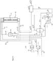
- FIG. 1 A reference example of the process is shown in Fig. 1 .
- the process takes liquid ammonia from storage (not shown).
- the ammonia to be cracked (line 2) is pumped (pump P201) as liquid to a pressure greater than the desired cracking pressure (see GB1142941 ).
- the reaction pressure is a compromise between operating pressure and conversion according to Le Chatelier's principle. There is an incentive to operate the reactor (8) at higher pressure because pumping liquid ammonia requires less power and capital than compressing the product hydrogen.
- the pressurised liquid ammonia (line 4) is then heated, vaporised (if it is below its critical pressure) and heated further, up to a temperature of greater than 250 °C via a heat exchanger (E101) using the heat available in the cracked gas leaving the reaction tubes and the flue gas from the furnace.
- the heat exchanger (E101) is shown as one heat exchanger but, in practice, it will be a series of heat exchangers in a network.
- the initial heating and vaporization of the pressurized liquid ammonia may alternatively take place against an alternative heat source, such as cooling water or ambient air.
- Typical reaction temperatures are greater than 500 °C (see US2601221 ), palladium-based systems can run at 600 °C and 10 bar, whereas RenCat's metal oxide-based system runs at less than 300 °C and 1 bar .
- the operating pressure of the cracker is typically an optimization of several factors. Cracking of ammonia into hydrogen and nitrogen is favored by low pressure but other factors favor higher pressure, such as power consumption (which is minimized by pumping the feed ammonia rather than compressing the product hydrogen), and the PSA size (which is smaller at higher pressure).
- the hot ammonia enters reaction tubes of a reactor (8) at the desired pressure where additional heat is provided by the furnace (10) to crack the ammonia into nitrogen and hydrogen.
- the resulting mixture of residual ammonia, hydrogen and nitrogen exits (line 12) the reaction tubes of the reactor (8) at the reaction temperature and pressure.
- the reaction products are cooled in a heat exchanger (E101) against a combination of feed ammonia (from line 4), furnace fuel (in this case pumped ammonia from line 14, pump P202 and line 16; PSA tail gas from line 18; and product hydrogen in line 20) and combustion air (from line 22, fan K201 and line 24) to reduce the temperature as close as possible to that required for the inlet of a PSA device (26).
- Any residual heat in the cracked gas mixture is removed in a water cooler (not shown) to achieve an inlet temperature to the PSA device (26) of in a range from about 20°C to 60°C, e.g. about 50°C.
- the PSA product (line 30) is pure hydrogen compliant with ISO standard 14687 - Hydrogen Fuel Quality - with residual ammonia ⁇ 0.1 ppmv and nitrogen ⁇ 300 ppmv - at approximately the reaction pressure.
- the product hydrogen (line 30) is further compressed (not shown) for filling into tube trailers (not shown) for transport or it may be liquefied in a hydrogen liquefier (not shown) after any required compression.
- the PSA tail gas (line 18) or "purge gas" from the PSA device (26) is shown as being heated via the heat exchanger E101, using the cracked gas (line 12) leaving the reaction tubes of the reactor (8) or furnace flue gas (line 32), before being sent (in line 36) to the furnace as a combustion fuel.
- the PSA tail gas (line 18) may be fed directly to the furnace (10) without heating.
- the PSA tail gas may be preheated by an intermediate fluid, so as to allow a lower pressure for the PSA tail gas which increases hydrogen recovery.
- the resultant warmed ammonia fuel (line 34) and warmed hydrogen (line 40) are depicted as combined with the (optionally) warmed PSA tail gas (line 36) in a mixer (42) to produce a combined fuel which is fed (line 44) to the furnace (10) for combustion to generate the flue gas (line 32 and, after cooling in E101, line 48).
- a mixer 42 to produce a combined fuel which is fed (line 44) to the furnace (10) for combustion to generate the flue gas (line 32 and, after cooling in E101, line 48).
- one or more of the fuels could be fed directly to the furnace without prior mixing.
- the warmed air (for combustion with the fuel) is fed to the furnace (10) in line 46.
- One of the aims of the present process is to maximise the amount of H 2 generated by cracking the renewable ammonia. That means minimising the amount of H 2 used as fuel, or ammonia if ammonia were to be used as a fuel directly. Therefore, heat integration is important so as to use the hot flue gas and cracked gas appropriately, for instance to preheat air (line 24) and ammonia (line 4) to the cracker as this reduces the amount of "fuel” to be used in the burners of the furnace (10). This leads to higher hydrogen recovery as less of the hydrogen is lost in the furnace flue gas (lines 32 & 48) as water. Therefore, steam generation, for instance, should be minimised in favour of intra-process heat integration.
- Fig. 1 shows ammonia provided as fuel (lines 34 & 44) and feed (line 6) and it also shows product hydrogen as fuel (lines 40 & 44) - in practice, it is likely only one of these streams would be used as fuel.
- Fig. 2 depicts a similar process to that of Fig. 1 in which ammonia is used as a fuel (line 34) but not product hydrogen. All other features of the process depicted in Fig. 2 are the same as in Fig. 1 and the common features have been given the same reference numerals.
- Fig. 3 depicts a process similar to that depicted in Fig. 2 but which is driven only by the ammonia from the PSA.
- the recovery of hydrogen (line 30) from the PSA may be adjusted to provide a tail gas (line 18) which, when burned, will provide all the heat required by the process, thus eliminating the need for a trim fuel.
- All other features of the process depicted in Fig. 3 are the same as in Fig. 1 and the common features have been given the same reference numerals.
- Ammonia may need to be removed particularly but not exclusively if membranes are being used as part of the separation process since membrane material can be intolerant of high concentrations of ammonia and ammonia is a fast gas and would permeate with the hydrogen so would accumulate in the process if not removed.
- NH 3 may be removed for instance by a water wash or other well-known technology for ammonia removal, upstream of the membrane.
- the ammonia recovered in the ammonia removal step can be recovered to the feed to the cracking process using a stripping column to recover the ammonia from the water used to absorb the ammonia from the cracked gas. This could theoretically increase the hydrogen recovery from the process up to 100%.
- Recovering NH 3 from the cracked gas simplifies the hydrogen purification steps, may increase the recovery of hydrogen from the ammonia if the separated ammonia is recovered as feed, and also removes ammonia from the feed to the burners, significantly reduces concerns over production of NO x caused by burning NH 3 depending on the extent of the ammonia removal step.
- Water may also need to be removed from the feed ammonia to prevent damage to the ammonia cracking catalyst.
- ammonia has small quantities of water added to it to prevent stress corrosion cracking in vessels during shipping and storage. This might need to be removed.
- the water removal can be incorporated into the stripping column mentioned above.
- the ammonia would be evaporated at the required pressure, taking care in the design of the evaporator to ensure that the water was also carried through to the stripping column with the evaporator ammonia.
- This mostly vapour phase ammonia enters a mid-point of the column and pure ammonia leaves through the top of the column.
- the column has a partial condenser (condenses only enough liquid for the reflux) and the overhead vapour contains the feed ammonia (free of water) plus the ammonia recovered from the cracker gas stream.
- Fig. 4 depicts a process according to the present invention in which an aqueous ammonia stream (line 64) is recovered from the first PSA tail gas (line 54).
- the features of the process in Fig. 4 that are common to the processes of Figs. 1 to 3 have been given the same reference numerals. The following is a discussion of the new features in Fig. 4 .
- a fuel (line 50) is warmed in the heat exchange (E101) and combined with the (optionally) warmed PSA tail gas (line 36) to produce a combined fuel which is fed (line 44) to the furnace (10) for combustion to heat the catalyst-filled tubes of the cracking reactor (8) and to generate the flue gas (line 32 and, after cooling in E101 line 48).
- the warmed air is fed to the furnace (10) in line 46.
- the fuel (line 50) and the PSA tail gas (line 36) can be fed to the furnace separately without mixing (not shown).
- the cooled cracked gas (line 28) is fed to a first PSA device (26).
- the cracked gas is separated to form the hydrogen product (line 30) and tail gas (line 54).
- Part of the tail gas (line 54) from the first PSA is compressed in a compressor (K301) to produce compressed PSA tail gas (line 56).
- the compressed PSA tail gas (line 56) is chilled to a temperature in the range from about 10°C to about 60 °C and fed to the separator (58). Chilling of the compressed PSA tail gas can be achieved by heat exchange against one or more coolants selected from water, the cold feed ammonia and the one or more cooled fluids produced from heating the liquid ammonia (shown in Figure 4 , but cooling stream not numbered).
- Water (line 60) may optionally be added to the compressed first PSA tail gas to form a mixture comprising a cooled ammonia-depleted tail gas and aqueous ammonia solution. If water is present in the feed ammonia and does not need to be removed prior to cracking ( i.e. if the cracking catalyst is water-tolerant) then additional water may not be required. However, additional water may still be added as it aids the removal of ammonia from the PSA tail gas by acting as a solvent. The more water present, the more ammonia will be removed from the PSA; however, the concentration of the resulting ammonia solution will of course be lower. The concentration of the ammonia solution is typically from about 10 wt. % to about 30 wt. %, and preferably about 25 wt. %. The aim is not necessarily to remove all of the ammonia from the PSA tail gas but rather to provide a sufficient amount of ammonia solution for the selective catalytic reduction.
- the separator (58) may be any suitable separation device known in the art.
- the separator is preferably a simple phase separator or a separation column.
- the cooled ammonia depleted tail gas (line 62) is separated from the aqueous ammonia solution (line 64) and the aqueous ammonia solution (line 64) is fed to selective catalytic reduction (SCR) reactor (16).
- Cooled flue gas (line 48) is fed to the SCR reactor (16) where it is contacted with a selective reduction catalyst in the presence of the aqueous ammonia solution to convert NO X to nitrogen gas and water.
- the SCR reactor typically operates at a temperature in the range from about 200°C to about 500°C, preferably from about 300°C to about 400°C and so the reactor is positioned appropriately to operate at those temperatures.
- the cooled ammonia-depleted tail gas (line 62) or "purge gas" (line 18) from the first PSA device (26) is recycled to the first PSA device (26).
- the amount of PSA tail gas that is recycled corresponds to an increase in hydrogen recovery but will be approximately 50%.
- the ammonia-depleted tail gas (line 62) can be fed to a second PSA device (66).
- the product hydrogen from the second PSA device (line 70) is combined with the hydrogen product (line 30) to produce a combined hydrogen product gas (line 72) and to increase the amount of hydrogen produced in the process.
- the PSA tail gas (line 68) from the second PSA device (66) can be heated via the heat exchanger E101, using the cracked gas (line 12) leaving the reaction tubes or furnace flue gas (line 32), before being sent (in line 36) to the furnace (10) as a combustion fuel.
- the second PSA tail gas (line 68) may be fed directly to the furnace (10) without heating.
- the second PSA tail gas (line 68) may be heated by heat exchange with the one or more hot fluids.
- both the invention Examples and the Reference Examples assume an equilibrium for the cracking reaction at 11 bara and 500 °C.
- hydrogen recovery from the ammonia is 77.05% with the PSA recovery at 79.4%.
- the total power of the ammonia feed pump (P201) and the air fan (K201) is about 1.37 kW.
- the ammoniated water is 22.1 mol. % with a total molar flowrate of ammonia of 0.15 kmol/hr.
- the flow rate of the flue gas is 25 kmol/hr. If the flue gas contained 5000 ppm NO that would be 0.125 kmol/hr NO and therefore the NO could be removed by reacting with the ammonia recovered from the flue gas thereby saving on the requirement to have a separate supply of ammoniate solution.
Landscapes
- Chemical & Material Sciences (AREA)
- Engineering & Computer Science (AREA)
- Organic Chemistry (AREA)
- Combustion & Propulsion (AREA)
- Inorganic Chemistry (AREA)
- Health & Medical Sciences (AREA)
- Analytical Chemistry (AREA)
- Environmental & Geological Engineering (AREA)
- General Chemical & Material Sciences (AREA)
- Oil, Petroleum & Natural Gas (AREA)
- Chemical Kinetics & Catalysis (AREA)
- General Health & Medical Sciences (AREA)
- Biomedical Technology (AREA)
- Hydrogen, Water And Hydrids (AREA)
- Gas Separation By Absorption (AREA)
- Exhaust Gas Treatment By Means Of Catalyst (AREA)
- Separation Of Gases By Adsorption (AREA)
- Treating Waste Gases (AREA)
Claims (17)
- Verfahren zum Erzeugen von Wasserstoff aus Ammoniak, umfassend:Unterdrucksetzen von flüssigem Ammoniak für das Erzeugen eines unter Druck gesetzten flüssigen Ammoniaks,Erhitzen (und optional Verdampfen) des unter Druck gesetzten flüssigen Ammoniaks durch einen Wärmetausch mit einem oder mehreren heißen Fluiden für das Erzeugen eines erhitzten Ammoniaks,Verbrennen eines Brennstoffs in einem Ofen für das Erhitzen von Reaktorröhren mit einem darin enthaltenen Katalysator und für das Bilden eines Rauchgases, das Oxide von Stickstoff (NOx) enthält,Kontaktieren des Rauchgases mit einem Selektive-Reduktion-Katalysator in Anwesenheit von Ammoniak in einem Selektive-katalytische-Reduktion (SCR)-Reaktor für das Wandeln von NOx zu Stickstoffgas und Wasser,Zuführen des erhitzten Ammoniaks zu den einen Katalysator enthaltenden Reaktorröhren für das Veranlassen eines Spaltens des Ammoniaks in ein Spaltgas, das Wasserstoffgas, Stickstoffgas und restliches Ammoniak enthält,Reinigen des Spaltgases in einer ersten Druckwechsel-Adsorption (DWA)-Vorrichtung für das Erzeugen eines ersten Wasserstoffproduktgases und eines ersten DWA-Restgases, das Ammoniak enthält,Komprimieren wenigstens eines Teils des ersten DWA-Restgases für das Erzeugen eines komprimierten DWA-Restgases,Kühlen des komprimierten DWA-Restgases für das Erzeugen eines gekühlten ammoniakarmen Restgases und einer wässrigen Ammoniaklösung, undTrennen des gekühlten ammoniakarmen Restgases von der wässrigen Ammoniaklösung,wobei wenigstens ein Teil der getrennten wässrigen Ammoniaklösung zu dem SCR-Reaktor geführt wird, um das Ammoniak für die SCR-Reaktion vorzusehen, undwobei das eine oder die mehreren heißen Fluide das Rauchgas und/oder das Spaltgas umfassen.
- Verfahren nach Anspruch 1, wobei das komprimierte DWA-Restgas zu einer Temperatur von ungefähr 5°C bis ungefähr 60°C gekühlt wird.
- Verfahren nach Anspruch 1 oder 2, wobei das komprimierte DWA-Restgas durch einen Wärmetausch mit wenigstens einem Kühlmittel gekühlt wird, das aus Wasser, dem unter Druck gesetzten flüssigen Ammoniak und der einen oder den mehreren gekühlten Fluiden, die durch das Erhitzen des flüssigen Ammoniaks erzeugt werden, ausgewählt wird.
- Verfahren nach einem der vorstehenden Ansprüche, wobei Wasser zu dem komprimierten ersten DWA-Restgas hinzugefügt wird.
- Verfahren nach Anspruch 4, wobei das Wasser zu einer Temperatur unter ungefähr 25°C gekühlt wird, bevor es zu dem komprimierten ersten DWA-Restgas hinzugefügt wird.
- Verfahren nach einem der vorstehenden Ansprüche, wobei das flüssige Ammoniak zwischen 0,2 und 0,5 Gew.-% Wasser enthält.
- Verfahren nach einem der vorstehenden Ansprüche, das das Zurückführen des gekühlten, ammoniakarmen Restgases zu der ersten DWA-Vorrichtung für eine Reinigung mit dem Spaltgas oder dem daraus abgeleiteten ammoniakarmen Gas umfasst.
- Verfahren nach einem der Ansprüche 1 bis 6, das das Reinigen des gekühlten ammoniakarmen Restgases in einer zweiten DWA-Vorrichtung für das Erzeugen eines zweiten Wasserstoffproduktgases und eines zweiten DWA-Restgases umfasst.
- Verfahren nach Anspruch 8, wobei das zweite Wasserstoffproduktgas mit dem ersten Wasserstoffproduktgas kombiniert wird, um ein kombiniertes Wasserstoffproduktgas zu erzeugen.
- Verfahren nach einem der vorstehenden Ansprüche, wobei der in dem Ofen verbrannte Brennstoff Ammoniak, das erste DWA-Restgas, das zweite DWA-Restgas, Wasserstoff, Methan, das gekühlte ammoniakarme Restgas oder ein davon abgeleitetes Gas enthält.
- Verfahren nach den Ansprüchen 8 bis 10, wobei der in dem Ofen verbrannte Brennstoff das zweite DWA-Restgas enthält.
- Verfahren nach einem der vorstehenden Ansprüche, wobei der Selektive-Reduktion-Katalysator Titanoxid, Vanadiumoxid, Molybdänoxid, Wolframoxid oder ein Zeolith enthält.
- Verfahren nach einem der vorstehenden Ansprüche, wobei das erste DWA-Restgas zu einem Druck von ungefähr 5 bis ungefähr 50 bar komprimiert wird.
- Vorrichtung zum Erzeugen von Wasserstoff aus Ammoniak, umfassend:eine Pumpe zum Unterdrucksetzen von flüssigem Ammoniak für das Erzeugen eines unter Druck gesetzten flüssigen Ammoniaks,wenigstens einen ersten Wärmetauscher in einer Fluidverbindung mit der Pumpe für das Erhitzen (und optional Verdampfen) des unter Druck gesetzten flüssigen Ammoniaks von der Pumpe durch einen Wärmetausch mit einem oder mehreren heißen Fluiden,Reaktorröhren mit einem darin enthaltenen Katalysator und in einer Fluidverbindung mit dem oder den ersten Wärmetauschern für das Spalten des erhitzten Ammoniaks von dem oder den ersten Wärmetauschern für das Erzeugen eines ersten Spaltgases, das Wasserstoffgas, Stickstoffgas und restliches Ammoniak enthält,einen Ofen in einer thermischen Verbindung mit dem einen Katalysator enthaltenden Reaktorröhren für das Verbrennen eines Brennstoffs für das Erhitzen der einen Katalysator enthaltenden Reaktorröhren und das Bilden eines Rauchgases, das Oxide von Stickstoff (NOx) enthält,eine erste Druckwechsel-Adsorption (DWA)-Vorrichtung in einer Fluidverbindung mit dem einen Katalysator enthaltenden Reaktorröhren für das Reinigen des Spaltgases für das Erzeugen eines ersten Wasserstoffproduktgases und eines ersten DWA-Restgases,einen Kompressor in einer Fluidverbindung mit der ersten DWA-Vorrichtung für das Komprimieren wenigstens eines Teils des ersten DWA-Restgases für das Erzeugen eines komprimierten DWA-Restgases,wenigstens einen zweiten Wärmetauscher in einer Fluidverbindung mit dem Kompressor für das Kühlen des komprimierten DWA-Restgases für das Erzeugen eines gekühlten ammoniakarmen Restgases und einer wässrigen Ammoniaklösung,eine Trennvorrichtung in einer Fluidkommunikation mit dem oder den zweiten Wärmetauschern für das Trennen des gekühlten ammoniakarmen Restgases von der wässrigen Ammoniaklösung, undeinen Selektive-katalytische-Reduktion (SCR)-Reaktor in einer Fluidverbindung mit dem Ofen und der Trennvorrichtung für das Wandeln von NOx zu Stickstoffgas und Wasser,wobei die Vorrichtung eine Leitung für das Zuführen der wässrigen Ammoniaklösung zu dem SCR-Reaktor umfasst, undwobei die Vorrichtung eine Rauchgasleitung für das Zuführen des Rauchgases als eines heißen Fluids von dem Ofen zu dem oder den ersten Wärmetauschern und/oder eine Spaltgasleitung für das Zuführen des Spaltgases als eines heißen Fluids von den einen Katalysator enthaltenden Reaktorröhren zu dem oder den ersten Wärmetauschern umfasst.
- Vorrichtung nach Anspruch 14, die weiterhin eine Leitung für das Zurückführen des gekühlten ammoniakarmen Restgases zu der ersten DWA-Vorrichtung umfasst.
- Vorrichtung nach Anspruch 14, die weiterhin umfasst:eine zweite DWA-Vorrichtung in einer Fluidverbindung mit der Trennvorrichtung für das Reinigen des gekühlten ammoniakarmen Restgases für das Erzeugen eines zweiten Wasserstoffproduktgases und eines zweiten DWA-Restgases,eine zweite Wasserstoffgasleitung für das Entfernen des zweiten Wasserstoffgases aus der zweiten DWA-Vorrichtung, undeine zweite DWA-Restgas-Leitung für das Entfernen des zweiten DWA-Restgases aus der zweiten DWA-Vorrichtung,
- Vorrichtung nach einem der Ansprüche 14 bis 16, die weiterhin eine Leitung für das Zuführen von Wasser zu der Trennvorrichtung umfasst.
Applications Claiming Priority (1)
| Application Number | Priority Date | Filing Date | Title |
|---|---|---|---|
| PCT/US2021/037996 WO2022265648A1 (en) | 2021-06-18 | 2021-06-18 | Ammonia cracking for green hydrogen with nox removal |
Publications (2)
| Publication Number | Publication Date |
|---|---|
| EP4337598A1 EP4337598A1 (de) | 2024-03-20 |
| EP4337598B1 true EP4337598B1 (de) | 2025-06-11 |
Family
ID=76921314
Family Applications (1)
| Application Number | Title | Priority Date | Filing Date |
|---|---|---|---|
| EP21742232.8A Active EP4337598B1 (de) | 2021-06-18 | 2021-06-18 | Ammoniakspaltung für grünen wasserstoff mit nox-entfernung |
Country Status (9)
| Country | Link |
|---|---|
| US (1) | US20240279053A1 (de) |
| EP (1) | EP4337598B1 (de) |
| JP (1) | JP7672517B2 (de) |
| KR (1) | KR20240021941A (de) |
| CN (1) | CN117460686A (de) |
| AU (1) | AU2021451457A1 (de) |
| CA (1) | CA3223287A1 (de) |
| ES (1) | ES3040788T3 (de) |
| WO (1) | WO2022265648A1 (de) |
Families Citing this family (25)
| Publication number | Priority date | Publication date | Assignee | Title |
|---|---|---|---|---|
| CN117751089A (zh) * | 2021-06-18 | 2024-03-22 | 气体产品与化学公司 | 从氨裂化法中回收可再生氢产品 |
| KR20250140063A (ko) | 2022-12-23 | 2025-09-24 | 티센크룹 악티엔게젤샤프트 | Nh3로 작동되는 소각 플랜트로부터의 오프가스 내의 nox 및 n2o의 함량 감소 |
| KR102872978B1 (ko) * | 2022-12-30 | 2025-10-21 | 한국에너지기술연구원 | 암모니아 분해로부터 고순도의 수소 정제용 압력변동흡착장치 및 이를 이용한 수소 정제 방법 |
| CN116332537A (zh) * | 2023-03-23 | 2023-06-27 | 乌海市恒业煤化有限公司 | 一种氨燃料替代煤掺混煅烧水泥熟料的生产系统 |
| DE102023114700A1 (de) | 2023-06-05 | 2024-12-05 | Thyssenkrupp Ag | Reaktoren und Reaktorbauteile zur Zersetzung von NH3 bei hohen Temperaturen |
| KR20260005380A (ko) | 2023-06-05 | 2026-01-09 | 티센크루프 우데 게엠 베하 | 고온에서 nh3를 분해하기 위한 반응기 |
| LU103141B1 (de) | 2023-06-05 | 2024-12-05 | Thyssenkrupp Uhde Gmbh | Reaktoren und Reaktorbauteile zur Zersetzung von NH3 bei hohen Temperaturen |
| WO2024251713A1 (de) | 2023-06-06 | 2024-12-12 | Thyssenkrupp Uhde Gmbh | Katalytische zersetzung von ammoniak mit wasserdampf als wärmeträgermedium |
| DE102023114883A1 (de) | 2023-06-06 | 2024-12-12 | Thyssenkrupp Ag | Katalytische Zersetzung von Ammoniak mit Wasserdampf als Wärmeträgermedium |
| LU103144B1 (de) | 2023-06-06 | 2024-12-06 | Thyssenkrupp Uhde Gmbh | Katalytische Zersetzung von Ammoniak mit Wasserdampf als Wärmeträgermedium |
| LU103170B1 (de) | 2023-07-13 | 2025-01-13 | Thyssenkrupp Ag | Anfahren einer Anlage zur katalytischen Zersetzung von Ammoniak |
| DE102023118575A1 (de) | 2023-07-13 | 2025-01-16 | Thyssenkrupp Ag | Zersetzung von Ammoniak an Nickel-basierten Katalysatoren |
| LU103169B1 (de) | 2023-07-13 | 2025-01-13 | Thyssenkrupp Uhde Gmbh | Zersetzung von Ammoniak an Nickel-basierten Katalysatoren |
| WO2025012277A1 (de) | 2023-07-13 | 2025-01-16 | Thyssenkrupp Uhde Gmbh | Zersetzung von ammoniak an nickel-basierten katalysatoren |
| WO2025012271A1 (de) | 2023-07-13 | 2025-01-16 | Thyssenkrupp Uhde Gmbh | Anfahren einer anlage zur katalytischen zersetzung von ammoniak |
| WO2025014390A1 (ru) * | 2023-07-13 | 2025-01-16 | Публичное акционерное общество "НОВАТЭК" | Способ получения низкоуглеродного водорода и установка для его осуществления |
| DE102023118576A1 (de) | 2023-07-13 | 2025-01-16 | Thyssenkrupp Ag | Anfahren einer Anlage zur katalytischen Zersetzung von Ammoniak |
| BE1031850B1 (nl) | 2023-07-31 | 2025-03-04 | Duiker Combustion Eng B V | Een proces voor de productie van waterstof door thermische reforming van ammoniak |
| US20250144610A1 (en) | 2023-11-06 | 2025-05-08 | Air Products And Chemicals, Inc. | Apparatus and process for ammonia cracking catalyst activation |
| KR20250094140A (ko) * | 2023-12-18 | 2025-06-25 | 포스코홀딩스 주식회사 | 선박용 암모니아로부터 수소를 생산하는 장치 |
| GB202402672D0 (en) * | 2024-02-26 | 2024-04-10 | Johnson Matthey Plc | Process and system |
| US20250296836A1 (en) | 2024-03-21 | 2025-09-25 | Air Products And Chemicals, Inc. | Process and Apparatus for Cracking Ammonia |
| EP4635905A1 (de) * | 2024-04-16 | 2025-10-22 | Linde GmbH | Verfahren und anlage zur gewinnung eines wasserstoffprodukts unter verwendung von ammoniak |
| WO2025262091A1 (de) * | 2024-06-21 | 2025-12-26 | Thyssenkrupp Uhde Gmbh | Verfahren zum abbau von stickstoffoxiden in abgasen in mehreren reaktionsphasen |
| BE1032715B1 (de) * | 2024-06-21 | 2026-01-28 | Thyssenkrupp Uhde Gmbh | Verfahren zum Abbau von Stickstoffoxiden in Abgasen in mehreren Reaktionsphasen |
Family Cites Families (18)
| Publication number | Priority date | Publication date | Assignee | Title |
|---|---|---|---|---|
| BE625373A (de) | 1961-11-27 | |||
| GB1142941A (en) | 1965-02-16 | 1969-02-12 | Whessoe Ltd | Improvements in and relating to gas producing |
| JPS5330802B2 (de) | 1973-07-25 | 1978-08-29 | ||
| US6379431B1 (en) | 2000-01-20 | 2002-04-30 | Air Products And Chemicals, Inc. | Pressure swing adsorption process with multiple beds on purge and/or with ten beds and four pressure equalization steps |
| US6423279B1 (en) | 2000-10-16 | 2002-07-23 | Harvest Energy Technology, Inc. | Compact endothermic catalytic reaction apparatus |
| JP2008500932A (ja) * | 2004-05-05 | 2008-01-17 | グラウプナー,ロバート,ケー. | グアニジンベース組成物及びそのシステム |
| US7354560B2 (en) | 2006-01-31 | 2008-04-08 | Haldor Topsoe A/S | Process for the production of hydrogen |
| JP2009542568A (ja) * | 2006-06-27 | 2009-12-03 | フルオー・テクノロジーズ・コーポレイシヨン | 水素燃料供給の設備構成および方法 |
| CA2654823C (en) * | 2008-02-19 | 2016-06-21 | University Of Ontario Institute Of Technology | Methods and apparatus for using ammonia as sustainable fuel, refrigerant and nox reduction agent |
| WO2013119281A1 (en) * | 2012-02-10 | 2013-08-15 | Shawn Grannell | Ammonia flame cracker system, method and apparatus |
| US8778051B2 (en) | 2012-03-15 | 2014-07-15 | Air Products And Chemicals, Inc. | Pressure swing adsorption process |
| CN203892008U (zh) * | 2014-06-17 | 2014-10-22 | 厦门大学 | 一种氨发动机系统 |
| US9381460B2 (en) | 2014-09-11 | 2016-07-05 | Air Products And Chemicals, Inc. | Pressure swing adsorption process |
| WO2018185663A1 (en) * | 2017-04-04 | 2018-10-11 | Basf Corporation | On-board vehicle ammonia and hydrogen generation |
| EP3630682A4 (de) | 2017-05-26 | 2021-08-11 | Starfire Energy | Entfernung von gasförmigem nh3 aus einer nh3 reaktorproduktstrom |
| JP7226972B2 (ja) * | 2018-11-09 | 2023-02-21 | 好朗 岩井 | 水素ガス製造装置 |
| JP7285098B2 (ja) * | 2019-03-15 | 2023-06-01 | 三菱重工業株式会社 | アンモニア分解設備、これを備えるガスタービンプラント、アンモニア分解方法 |
| CN111957270B (zh) * | 2020-09-03 | 2024-10-22 | 福大紫金氢能科技股份有限公司 | 一种氨分解制氢系统及加氢站系统 |
-
2021
- 2021-06-18 ES ES21742232T patent/ES3040788T3/es active Active
- 2021-06-18 CA CA3223287A patent/CA3223287A1/en active Pending
- 2021-06-18 KR KR1020247001480A patent/KR20240021941A/ko active Pending
- 2021-06-18 WO PCT/US2021/037996 patent/WO2022265648A1/en not_active Ceased
- 2021-06-18 EP EP21742232.8A patent/EP4337598B1/de active Active
- 2021-06-18 CN CN202180099166.1A patent/CN117460686A/zh active Pending
- 2021-06-18 AU AU2021451457A patent/AU2021451457A1/en active Pending
- 2021-06-18 JP JP2023577372A patent/JP7672517B2/ja active Active
- 2021-06-18 US US18/569,461 patent/US20240279053A1/en active Pending
Also Published As
| Publication number | Publication date |
|---|---|
| CA3223287A1 (en) | 2022-12-22 |
| KR20240021941A (ko) | 2024-02-19 |
| US20240279053A1 (en) | 2024-08-22 |
| ES3040788T3 (en) | 2025-11-05 |
| WO2022265648A1 (en) | 2022-12-22 |
| CN117460686A (zh) | 2024-01-26 |
| AU2021451457A1 (en) | 2024-02-01 |
| EP4337598A1 (de) | 2024-03-20 |
| JP7672517B2 (ja) | 2025-05-07 |
| JP2024524089A (ja) | 2024-07-05 |
Similar Documents
| Publication | Publication Date | Title |
|---|---|---|
| EP4337598B1 (de) | Ammoniakspaltung für grünen wasserstoff mit nox-entfernung | |
| EP4337600B1 (de) | Ammoniak-crackverfahren | |
| EP4337599B1 (de) | Ammoniakspaltung für grünen wasserstoff | |
| US20230242395A1 (en) | Ammonia Cracking for Green Hydrogen | |
| US20240270569A1 (en) | Recovery of a renewable hydrogen product from an ammonia cracking process |
Legal Events
| Date | Code | Title | Description |
|---|---|---|---|
| STAA | Information on the status of an ep patent application or granted ep patent |
Free format text: STATUS: UNKNOWN |
|
| STAA | Information on the status of an ep patent application or granted ep patent |
Free format text: STATUS: THE INTERNATIONAL PUBLICATION HAS BEEN MADE |
|
| PUAI | Public reference made under article 153(3) epc to a published international application that has entered the european phase |
Free format text: ORIGINAL CODE: 0009012 |
|
| STAA | Information on the status of an ep patent application or granted ep patent |
Free format text: STATUS: REQUEST FOR EXAMINATION WAS MADE |
|
| 17P | Request for examination filed |
Effective date: 20231127 |
|
| AK | Designated contracting states |
Kind code of ref document: A1 Designated state(s): AL AT BE BG CH CY CZ DE DK EE ES FI FR GB GR HR HU IE IS IT LI LT LU LV MC MK MT NL NO PL PT RO RS SE SI SK SM TR |
|
| DAV | Request for validation of the european patent (deleted) | ||
| DAX | Request for extension of the european patent (deleted) | ||
| GRAP | Despatch of communication of intention to grant a patent |
Free format text: ORIGINAL CODE: EPIDOSNIGR1 |
|
| STAA | Information on the status of an ep patent application or granted ep patent |
Free format text: STATUS: GRANT OF PATENT IS INTENDED |
|
| INTG | Intention to grant announced |
Effective date: 20250212 |
|
| GRAS | Grant fee paid |
Free format text: ORIGINAL CODE: EPIDOSNIGR3 |
|
| GRAA | (expected) grant |
Free format text: ORIGINAL CODE: 0009210 |
|
| STAA | Information on the status of an ep patent application or granted ep patent |
Free format text: STATUS: THE PATENT HAS BEEN GRANTED |
|
| AK | Designated contracting states |
Kind code of ref document: B1 Designated state(s): AL AT BE BG CH CY CZ DE DK EE ES FI FR GB GR HR HU IE IS IT LI LT LU LV MC MK MT NL NO PL PT RO RS SE SI SK SM TR |
|
| P01 | Opt-out of the competence of the unified patent court (upc) registered |
Free format text: CASE NUMBER: APP_21064/2025 Effective date: 20250505 |
|
| REG | Reference to a national code |
Ref country code: GB Ref legal event code: FG4D |
|
| REG | Reference to a national code |
Ref country code: CH Ref legal event code: EP |
|
| REG | Reference to a national code |
Ref country code: IE Ref legal event code: FG4D |
|
| REG | Reference to a national code |
Ref country code: DE Ref legal event code: R096 Ref document number: 602021032140 Country of ref document: DE |
|
| PGFP | Annual fee paid to national office [announced via postgrant information from national office to epo] |
Ref country code: DE Payment date: 20250521 Year of fee payment: 5 |
|
| PGFP | Annual fee paid to national office [announced via postgrant information from national office to epo] |
Ref country code: GB Payment date: 20250616 Year of fee payment: 5 |
|
| PGFP | Annual fee paid to national office [announced via postgrant information from national office to epo] |
Ref country code: NL Payment date: 20250616 Year of fee payment: 5 Ref country code: BE Payment date: 20250526 Year of fee payment: 5 |
|
| PGFP | Annual fee paid to national office [announced via postgrant information from national office to epo] |
Ref country code: FR Payment date: 20250523 Year of fee payment: 5 |
|
| PGFP | Annual fee paid to national office [announced via postgrant information from national office to epo] |
Ref country code: AT Payment date: 20250721 Year of fee payment: 5 |
|
| REG | Reference to a national code |
Ref country code: NL Ref legal event code: FP |
|
| PG25 | Lapsed in a contracting state [announced via postgrant information from national office to epo] |
Ref country code: FI Free format text: LAPSE BECAUSE OF FAILURE TO SUBMIT A TRANSLATION OF THE DESCRIPTION OR TO PAY THE FEE WITHIN THE PRESCRIBED TIME-LIMIT Effective date: 20250611 |
|
| PGFP | Annual fee paid to national office [announced via postgrant information from national office to epo] |
Ref country code: ES Payment date: 20250704 Year of fee payment: 5 |
|
| REG | Reference to a national code |
Ref country code: LT Ref legal event code: MG9D |
|
| PG25 | Lapsed in a contracting state [announced via postgrant information from national office to epo] |
Ref country code: GR Free format text: LAPSE BECAUSE OF FAILURE TO SUBMIT A TRANSLATION OF THE DESCRIPTION OR TO PAY THE FEE WITHIN THE PRESCRIBED TIME-LIMIT Effective date: 20250912 Ref country code: NO Free format text: LAPSE BECAUSE OF FAILURE TO SUBMIT A TRANSLATION OF THE DESCRIPTION OR TO PAY THE FEE WITHIN THE PRESCRIBED TIME-LIMIT Effective date: 20250911 |
|
| PGFP | Annual fee paid to national office [announced via postgrant information from national office to epo] |
Ref country code: IT Payment date: 20250916 Year of fee payment: 5 |
|
| PG25 | Lapsed in a contracting state [announced via postgrant information from national office to epo] |
Ref country code: BG Free format text: LAPSE BECAUSE OF FAILURE TO SUBMIT A TRANSLATION OF THE DESCRIPTION OR TO PAY THE FEE WITHIN THE PRESCRIBED TIME-LIMIT Effective date: 20250611 |
|
| PG25 | Lapsed in a contracting state [announced via postgrant information from national office to epo] |
Ref country code: HR Free format text: LAPSE BECAUSE OF FAILURE TO SUBMIT A TRANSLATION OF THE DESCRIPTION OR TO PAY THE FEE WITHIN THE PRESCRIBED TIME-LIMIT Effective date: 20250611 |
|
| PG25 | Lapsed in a contracting state [announced via postgrant information from national office to epo] |
Ref country code: RS Free format text: LAPSE BECAUSE OF FAILURE TO SUBMIT A TRANSLATION OF THE DESCRIPTION OR TO PAY THE FEE WITHIN THE PRESCRIBED TIME-LIMIT Effective date: 20250911 |
|
| PG25 | Lapsed in a contracting state [announced via postgrant information from national office to epo] |
Ref country code: LV Free format text: LAPSE BECAUSE OF FAILURE TO SUBMIT A TRANSLATION OF THE DESCRIPTION OR TO PAY THE FEE WITHIN THE PRESCRIBED TIME-LIMIT Effective date: 20250611 |
|
| REG | Reference to a national code |
Ref country code: ES Ref legal event code: FG2A Ref document number: 3040788 Country of ref document: ES Kind code of ref document: T3 Effective date: 20251105 |
|
| PG25 | Lapsed in a contracting state [announced via postgrant information from national office to epo] |
Ref country code: PT Free format text: LAPSE BECAUSE OF FAILURE TO SUBMIT A TRANSLATION OF THE DESCRIPTION OR TO PAY THE FEE WITHIN THE PRESCRIBED TIME-LIMIT Effective date: 20251013 |
|
| REG | Reference to a national code |
Ref country code: AT Ref legal event code: MK05 Ref document number: 1802227 Country of ref document: AT Kind code of ref document: T Effective date: 20250611 |
|
| PG25 | Lapsed in a contracting state [announced via postgrant information from national office to epo] |
Ref country code: IS Free format text: LAPSE BECAUSE OF FAILURE TO SUBMIT A TRANSLATION OF THE DESCRIPTION OR TO PAY THE FEE WITHIN THE PRESCRIBED TIME-LIMIT Effective date: 20251011 |
|
| PG25 | Lapsed in a contracting state [announced via postgrant information from national office to epo] |
Ref country code: SM Free format text: LAPSE BECAUSE OF FAILURE TO SUBMIT A TRANSLATION OF THE DESCRIPTION OR TO PAY THE FEE WITHIN THE PRESCRIBED TIME-LIMIT Effective date: 20250611 Ref country code: AT Free format text: LAPSE BECAUSE OF FAILURE TO SUBMIT A TRANSLATION OF THE DESCRIPTION OR TO PAY THE FEE WITHIN THE PRESCRIBED TIME-LIMIT Effective date: 20250611 |
|
| PG25 | Lapsed in a contracting state [announced via postgrant information from national office to epo] |
Ref country code: CZ Free format text: LAPSE BECAUSE OF FAILURE TO SUBMIT A TRANSLATION OF THE DESCRIPTION OR TO PAY THE FEE WITHIN THE PRESCRIBED TIME-LIMIT Effective date: 20250611 |
|
| PG25 | Lapsed in a contracting state [announced via postgrant information from national office to epo] |
Ref country code: PL Free format text: LAPSE BECAUSE OF FAILURE TO SUBMIT A TRANSLATION OF THE DESCRIPTION OR TO PAY THE FEE WITHIN THE PRESCRIBED TIME-LIMIT Effective date: 20250611 |
|
| PG25 | Lapsed in a contracting state [announced via postgrant information from national office to epo] |
Ref country code: EE Free format text: LAPSE BECAUSE OF FAILURE TO SUBMIT A TRANSLATION OF THE DESCRIPTION OR TO PAY THE FEE WITHIN THE PRESCRIBED TIME-LIMIT Effective date: 20250611 |
|
| PG25 | Lapsed in a contracting state [announced via postgrant information from national office to epo] |
Ref country code: SK Free format text: LAPSE BECAUSE OF FAILURE TO SUBMIT A TRANSLATION OF THE DESCRIPTION OR TO PAY THE FEE WITHIN THE PRESCRIBED TIME-LIMIT Effective date: 20250611 |
|
| REG | Reference to a national code |
Ref country code: CH Ref legal event code: H13 Free format text: ST27 STATUS EVENT CODE: U-0-0-H10-H13 (AS PROVIDED BY THE NATIONAL OFFICE) Effective date: 20260127 |