EP4337584B1 - Aufzugssystem und -verfahren - Google Patents
Aufzugssystem und -verfahren Download PDFInfo
- Publication number
- EP4337584B1 EP4337584B1 EP21726588.3A EP21726588A EP4337584B1 EP 4337584 B1 EP4337584 B1 EP 4337584B1 EP 21726588 A EP21726588 A EP 21726588A EP 4337584 B1 EP4337584 B1 EP 4337584B1
- Authority
- EP
- European Patent Office
- Prior art keywords
- elevator car
- floor
- elevator
- height
- floor elements
- Prior art date
- Legal status (The legal status is an assumption and is not a legal conclusion. Google has not performed a legal analysis and makes no representation as to the accuracy of the status listed.)
- Active
Links
Images

Classifications
-
- B—PERFORMING OPERATIONS; TRANSPORTING
- B66—HOISTING; LIFTING; HAULING
- B66B—ELEVATORS; ESCALATORS OR MOVING WALKWAYS
- B66B11/00—Main component parts of lifts in, or associated with, buildings or other structures
- B66B11/02—Cages, i.e. cars
Definitions
- This invention relates to an elevator system and to a method for operating an elevator system, and more particularly to a multipurpose elevator system.
- a challenge with traditional elevators is that the provided elevator car is usually optimized for transporting persons.
- the provided elevator car is usually optimized for transporting persons.
- Figure 1 illustrates a simplified side view of an elevator system 1 with an elevator car 2 which is arranged to move vertically in a hoistway 3 between landings 4 of a building 16.
- the elevator car is moved by a hoisting machinery 5 which is controlled by an elevator control 6.
- the hoisting machinery 5 utilizes a rope 18 to move the elevator car 2 and a counterweight 19 in the hoistway 3.
- Figures 1 and 2 One alternative is to utilize a similar solution as illustrated in Figure 5 .
- An advantage with the rolling surface 10 provided by the rolls 7 is that when loading or unloading cargo into the elevator car 2, the cargo can slide along the rolling surface due to the rotation of the rolls 7. This significantly simplifies loading and unloading of heavy cargo.
- the elevator car 2 is provided with a floor section comprising one or more floor elements 11, which are movable between a load bearing position, where the one or more floor elements are aligned on top of the rolling floor surface 10 and provide a fixed floor surface, and a transport position, where the rolling floor surface 10 is revealed.
- Figure 1 illustrates the one or more floor elements 11 in the transport position, where the elevator car is optimized for transport of cargo
- Figure 2 illustrates the one or more floor elements 11 in the load bearing position, where the one or more floor elements 11 are aligned on top of the rolling floor surface 10 and provide a fixed floor surface for carrying the weight of person standing on it.
- the elevator car 2 is provided with two floor elements 11, which are movable between the load bearing position and the transport position by rotation around pivot points 12.
- each of the floor elements 11 is separately attached by pivot points to the elevator car, preferably proximate to the opposite side walls of the elevator car.
- Proximity to the side walls 17 is advantageous, as in that case the area of the rolling surface 10 becomes as large as possible in the transport position.
- the pivot points 12 make it possible to lift each floor element 11 from the horizontal load bearing position illustrated in Figure 2 to an upright vertical transport position illustrated in Figure 1 .
- each floor element is located along a side wall 17 of the elevator car in an upright position, due to which the rolling surface 10 is revealed between the two floor elements.
- the elevator car may be provided with a drive unit 13 (or drive units) such as an electric motor, a hydraulic motor or hydraulic cylinder, or a pneumatic motor or pneumatic cylinder which can be used to move the one or more floor elements 11 between the load bearing position and the transport position.
- a control panel of the elevator car for instance, may be used to control the movement of the one or more floor elements 11 by utilizing electric power, hydraulic power or pneumatic power.
- Still another alternative for moving the one or more floor elements 11 into the transport position is to completely remove the elements from the elevator car 2 to an elevator landing 4.
- the elevator car may be provided with attachment points for attaching the one or more floor elements in position with screws (if needed), for instance, when the one or more floor elements 11 are in the load bearing position.
- the elevator car 2 is provided with a sensor 14 providing the elevator control 6 with an indication about the position of the one or more floor elements 11.
- the elevator control obtains information when the one or more floor elements 11 are in the transport position and when they are in the load bearing position. This information is useful, because it may be advantageous to stop the elevator car at different heights in the hoistway 3 in relation to the landings 4 depending on the position of the one or more floor elements 11.
- the elevator control 6 is configured to stop the elevator car 2 at a higher position in relation to the landing 4 when the one or more floor elements 11 are in the transport position, than when the one or more floor elements 11 are in the load bearing position.
- a construction time modification of the elevator car illustrated in Figures 1 and 2 may be utilized only during the construction time of the building. Consequently, for the construction time of the building the elevator car 2 may be set in a hybrid mode, where the rolling floor surface 10 and the one or more floor elements 11 have been provided to the floor 20 of the elevator car. Atthat stage, the elevator car is well suited for both transport of cargo and passengers, depending on if the one or more floor elements 11 are in the passenger load bearing position illustrated in Figure 1 or in the transport position illustrated in Figure 2 . However, once the construction time modification is no longer needed as the building is completed, this hybrid mode may no longer be needed.
- the elevator car may be set in a person transport mode, by removing the rolls providing the rolling floor surface 10 and the floor elements 11. Consequently, the floor 20 of the elevator car may be revealed and possibly provided with a new coating for more permanent transport of passengers.
- the elevator control 6 may, if necessary, be set into a new mode ensuring that the upper surface of the floor 20 is at the same level as the upper surface of the landings 4 in the hoistway, when the elevator car 2 stops at a landing.
- Figures 3 to 5 illustrate a second embodiment of an elevator car 2'.
- the second embodiment is very similar as the one explained in connection with Figures 1 to 2 . Therefore, in the following, the embodiment of Figures 3 to 5 will mainly be explained by pointing out the differences.
- the elevator car is set into a hybrid mode, for the construction time of the building, for instance, due to which it is provided with rolls 7 providing a rolling surface 10 and one or more floor elements 11, which can be moved between the cargo transport position (illustrated in Figure 3 ) and the passenger load bearing position, as has been illustrated and explained in connection with Figures 1 and 2 .
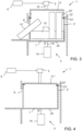
- the elevator car has additionally been provided with a height adjustable roof construction to obtain an increased interior height well suited for loading of long or high objects 15' into an elevator car 2'.
- objects 15' which are higher than the height of the door opening 9' in the elevator car 2' can easily be loaded onto the rolling floor surface by tilting at the door, and subsequently turning into an upright position. After this the objects 15' can slide deeper into the elevator car 2' on the rolling surface.
- a first alternative is to provide one single roof element 21' which can be attached in at least two alternative height positions to the elevator car 2'. This has been illustrated in Figure 3 by way of example.
- the roof element 21' has attachment holes 22' at two different vertical heights, so that bolts 23' can protrude through the holes 22' on the selected height and attach the roof element 21' at a desired height position to the walls of the elevator car 2'.
- Bolts and holes are naturally only one example of devices suitable for providing height adjustment for a single roof element 21'.
- FIG. 3 Another alternative to provide a height adjustable roof construction is to utilize two different roof elements.
- first roof element 21' illustrated in Figure 3 which provides an increased interior height for the elevator car 2' is replaced by a second roof element 21" as illustrated in Figure 4 , when the increased interior height is no longer necessary.
- attachment of the second roof element 21" may be implemented with bolts 23', for instance.
- Figure 5 illustrates in more detail an example of how the hoisting carried out with the hoisting machinery 5 and the rope 18 can be implemented. This solution can be utilized both for the embodiment of Figures 1 to 2 and for the embodiment of Figures 3 to 4 .
Landscapes
- Engineering & Computer Science (AREA)
- Civil Engineering (AREA)
- Mechanical Engineering (AREA)
- Structural Engineering (AREA)
- Elevator Control (AREA)
Claims (15)
- Aufzugssystem (1, 1'), umfassend:einen Aufzugsschacht (3),eine Aufzugskabine (2, 2'), die in dem Aufzugsschacht eingerichtet ist, undeine Aufzugssteuerung (6), welche die Aufzugskabine (2, 2') steuert, um sich vertikal in dem Aufzugsschacht (3) zwischen Absätzen (4) eines Gebäudes (16) zu bewegen, wobeiein Boden (20) der Aufzugskabine (2, 2') mit mindestens einer ersten und einer zweiten Rolle (7) versehen ist, die drehbar in der Aufzugskabine zur Drehung um Drehachsen (8), die parallel zu einer Türöffnung (9, 9') der Aufzugskabine sind, zum Bereitstellen einer Rollbodenoberfläche (10) aufgehängt sind, dadurch gekennzeichnet, dasseine Bodensektion, die ein oder mehrere Bodenelemente (11) umfasst, die zwischen einer lasttragenden Position, wo die Bodenelemente (11) oben auf der Rollbodenoberfläche (10) ausgerichtet sind und eine feste Bodenoberfläche bereitstellen, und einer Transportposition beweglich sind, wo die Rollbodenoberfläche (10) in der Aufzugskabine (2, 2') sichtbar ist.
- Aufzugssystem nach Anspruch 1, wobei das eine oder die mehreren Bodenelemente (11) zwischen der lasttragenden Position und der Transportposition durch Drehung um Drehpunkte (12) beweglich sind.
- Aufzugssystem nach Anspruch 2, wobei die Drehpunkte (12) in der Nähe der Wände (17) der Aufzugskabine (2, 2') eingerichtet sind.
- Aufzugssystem nach Anspruch 2 oder 3, wobei die Drehpunkte (12) durch Scharniere bereitgestellt sind.
- Aufzugssystem nach einem der Ansprüche 2 bis 4, wobei die Aufzugskabine (2, 2') mit einer Antriebseinheit (13) zum Drehen des einen oder der mehreren Bodenelemente (11) um die Drehpunkte (12) versehen ist.
- Aufzugssystem nach Anspruch 5, wobei die Antriebseinheit (13) das eine oder die mehreren Bodenelemente (11) durch elektrische Leistung, hydraulische Leistung oder pneumatische Leistung um die Drehpunkte (12) dreht.
- Aufzugssystem nach einem der Ansprüche 1 bis 6, wobeidie Aufzugskabine (2, 2') mit einem Sensor (14) versehen ist, welcher der Aufzugssteuerung (6) eine Angabe über die Position des einen oder der mehreren Bodenelemente (11) bereitstellt, unddie Aufzugssteuerung dazu ausgestaltet ist, das Anhalten der Aufzugskabine (2, 2') auf unterschiedlichen Höhen in Bezug auf einen Absatz (4) des Aufzugsschachts (3) abhängig davon zu steuern, ob das eine oder die mehreren Bodenelemente (11) sich in der lasttragenden Position oder in der Transportposition befinden.
- Aufzugssystem nach Anspruch 7, wobei
die Aufzugssteuerung (6) dazu ausgestaltet ist, die Aufzugskabine (2, 2'), wenn das eine oder die mehreren Bodenelemente (11) sich in der Transportposition befindet bzw. befinden, an einer höheren Position in Bezug auf den Absatz (4) anzuhalten als wenn das eine oder die mehreren Bodenelemente (11) sich in der lasttragenden Position befindet bzw. befinden. - Aufzugssystem nach einem der Ansprüche 1 bis 8, wobei die Aufzugssteuerung (6) die Aufzugskabine (2, 2') steuert, um auf einer Höhe anzuhalten, wo eine obere Oberfläche des einen oder der mehreren Bodenelemente (11) sich auf der gleichen Höhe befindet wie eine obere Oberfläche des Absatzes (4), wenn das eine oder die mehreren Bodenelemente (11) sich in der lasttragenden Position befindet bzw. befinden.
- Aufzugssystem nach einem der Ansprüche 1 bis 9, wobei die Aufzugssteuerung (6) die Aufzugskabine (2, 2') steuert, um auf einer Höhe anzuhalten, wo die Rollbodenoberfläche (10) sich auf der gleichen Höhe wie oder über der oberen Oberfläche des Absatzes (4) befindet, wenn das eine oder die mehreren Bodenelemente (11) sich in der Transportposition befindet bzw. befinden.
- Aufzugssystem nach einem der Ansprüche 1 bis 10, wobei die Aufzugskabine (2') mit einer höhenverstellbaren Dachkonstruktion versehen ist, wo die Innenhöhe in der Aufzugskabine (2') durch Anbringen eines einzigen Dachelements (21') in mindestens zwei alternativen Höhenpositionen oder durch Ersetzen eines ersten Dachelements (21') mit einem zweiten Dachelement (21") verstellt werden kann, das eine unterschiedliche Innenhöhe bereitstellt als das erste Dachelement.
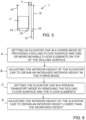
- Verfahren für den Betrieb eines Aufzugssystems, dadurch gekennzeichnet, dass das Verfahren umfasst:Einstellen (A) der Aufzugskabine in einem hybriden Modus durch Versehen eines Bodens (20) der Aufzugskabine (2, 2') mit einer Rollbodenoberfläche (10) und durch Versehen der Aufzugskabine mit einer Bodensektion, die ein oder mehrere Bodenelemente (11) umfasst, die zwischen einer lasttragenden Position, wo die Bodenelemente (11) oben auf der Rollbodenoberfläche (10) ausgerichtet sind, und einer Transportposition beweglich sind, wo die Rollbodenoberfläche (10) in der Aufzugskabine (2, 2') sichtbar ist, undEinstellen (C) der Aufzugskabine (2') in einem Personentransportmodus durch Entfernen der Rollbodenoberfläche (10) und des einen oder der mehreren Bodenelemente (11) von der Aufzugskabine, um den Boden der Aufzugskabine sichtbar zu machen.
- Verfahren nach Anspruch 12, wobei das Einstellen der Aufzugskabine (2') im hybriden Modus das Verstellen (B) einer Innenhöhe der Aufzugskabine (2') durch eine höhenverstellbare Dachkonstruktion umfasst, um eine erhöhte Innenhöhe zu erhalten.
- Verfahren nach Anspruch 13, wobei die Höhenverstellung das Anbringen eines einzigen Dachelements (21') der Aufzugskabine (2') auf eine höhere von mindestens zwei alternativen Anbringungspositionen oder das Ersetzen eines ersten Dachelements (21') mit einem zweiten Dachelement (21") umfasst, das eine unterschiedliche Innenhöhe als das erste Dachelement bereitstellt.
- Verfahren nach einem der Ansprüche 13 bis 14, wobei das Einstellen (D) der Aufzugskabine (2') in dem Personentransportmodus das Verstellen der Innenhöhe der Aufzugskabine (2') auf eine niedrigere Höhe als die erhöhte Innenhöhe umfasst.
Applications Claiming Priority (1)
| Application Number | Priority Date | Filing Date | Title |
|---|---|---|---|
| PCT/EP2021/062362 WO2022237959A1 (en) | 2021-05-10 | 2021-05-10 | An elevator system and method |
Publications (2)
| Publication Number | Publication Date |
|---|---|
| EP4337584A1 EP4337584A1 (de) | 2024-03-20 |
| EP4337584B1 true EP4337584B1 (de) | 2025-07-02 |
Family
ID=76011912
Family Applications (1)
| Application Number | Title | Priority Date | Filing Date |
|---|---|---|---|
| EP21726588.3A Active EP4337584B1 (de) | 2021-05-10 | 2021-05-10 | Aufzugssystem und -verfahren |
Country Status (3)
| Country | Link |
|---|---|
| EP (1) | EP4337584B1 (de) |
| CN (1) | CN117222591A (de) |
| WO (1) | WO2022237959A1 (de) |
Family Cites Families (7)
| Publication number | Priority date | Publication date | Assignee | Title |
|---|---|---|---|---|
| JPS55132081U (de) * | 1979-03-14 | 1980-09-18 | ||
| JP2000211856A (ja) * | 1999-01-25 | 2000-08-02 | Mitsubishi Electric Building Techno Service Co Ltd | エレベ―タ―のかご装置 |
| CN208308205U (zh) * | 2018-05-24 | 2019-01-01 | 广东弗兰斯勒电梯有限公司 | 货运电梯 |
| CN209127832U (zh) * | 2018-08-23 | 2019-07-19 | 山东奥德堡电梯股份有限公司 | 一种助力式载货电梯轿厢地板 |
| CN209651684U (zh) * | 2019-02-22 | 2019-11-19 | 湖南玖通电梯科技有限公司 | 一种便于调节空间大小的货物运输用电梯 |
| CN209797213U (zh) * | 2019-03-29 | 2019-12-17 | 快意电梯股份有限公司 | 电梯轿厢及具有该电梯轿厢的载货电梯 |
| CN109911745B (zh) * | 2019-03-29 | 2023-10-20 | 快意电梯股份有限公司 | 电梯轿厢、载货电梯及载货电梯的载货方法 |
-
2021
- 2021-05-10 EP EP21726588.3A patent/EP4337584B1/de active Active
- 2021-05-10 CN CN202180097740.XA patent/CN117222591A/zh active Pending
- 2021-05-10 WO PCT/EP2021/062362 patent/WO2022237959A1/en not_active Ceased
Also Published As
| Publication number | Publication date |
|---|---|
| WO2022237959A1 (en) | 2022-11-17 |
| EP4337584A1 (de) | 2024-03-20 |
| CN117222591A (zh) | 2023-12-12 |
Similar Documents
| Publication | Publication Date | Title |
|---|---|---|
| CA2749243C (en) | Elevator arrangement and method | |
| US11548762B2 (en) | Elevator car, elevator and method | |
| US20110024239A1 (en) | Operating method for an elevator with two elevator cars and a counterweight | |
| AU2021201478B2 (en) | Method for modernizing elevator system | |
| US20150197410A1 (en) | Elevator arrangement | |
| CN114829288B (zh) | 电梯装置和方法 | |
| US12312212B2 (en) | Elevator car and construction-time elevator arrangement and method | |
| US5816368A (en) | Elevator cars switch hoistways while traveling vertically | |
| EP4337584B1 (de) | Aufzugssystem und -verfahren | |
| EP1914188B1 (de) | Aufzugsvorrichtung | |
| HK40098624A (zh) | 电梯系统和方法 | |
| WO2009036232A2 (en) | Elevator systems and methods for operating same | |
| CN116601102A (zh) | 电梯的建造装置和方法 | |
| JP2002087722A (ja) | エレベータの駆動補助装置及びそれを用いた着床レベル調整方法 | |
| HK40059881A (en) | Elevator car, elevator and method | |
| HK40061526A (en) | Method for modernizing elevator system | |
| EP4622904A1 (de) | Transportbox oberhalb einer aufzugskabine, aufzug und verfahren zum transportieren von objekten | |
| EP4547595A1 (de) | Anordnung und verfahren zum bau eines aufzugs | |
| HK40085915A (en) | Elevator system | |
| HK40076777A (en) | Elevator arrangement and method | |
| HK40043051A (en) | Elevator car and construction-time elevator arrangement and method | |
| JP2005289614A (ja) | エレベータ装置及び制御方法 |
Legal Events
| Date | Code | Title | Description |
|---|---|---|---|
| STAA | Information on the status of an ep patent application or granted ep patent |
Free format text: STATUS: UNKNOWN |
|
| STAA | Information on the status of an ep patent application or granted ep patent |
Free format text: STATUS: THE INTERNATIONAL PUBLICATION HAS BEEN MADE |
|
| PUAI | Public reference made under article 153(3) epc to a published international application that has entered the european phase |
Free format text: ORIGINAL CODE: 0009012 |
|
| STAA | Information on the status of an ep patent application or granted ep patent |
Free format text: STATUS: REQUEST FOR EXAMINATION WAS MADE |
|
| 17P | Request for examination filed |
Effective date: 20231208 |
|
| AK | Designated contracting states |
Kind code of ref document: A1 Designated state(s): AL AT BE BG CH CY CZ DE DK EE ES FI FR GB GR HR HU IE IS IT LI LT LU LV MC MK MT NL NO PL PT RO RS SE SI SK SM TR |
|
| P01 | Opt-out of the competence of the unified patent court (upc) registered |
Effective date: 20240404 |
|
| DAV | Request for validation of the european patent (deleted) | ||
| DAX | Request for extension of the european patent (deleted) | ||
| GRAP | Despatch of communication of intention to grant a patent |
Free format text: ORIGINAL CODE: EPIDOSNIGR1 |
|
| STAA | Information on the status of an ep patent application or granted ep patent |
Free format text: STATUS: GRANT OF PATENT IS INTENDED |
|
| INTG | Intention to grant announced |
Effective date: 20250207 |
|
| GRAS | Grant fee paid |
Free format text: ORIGINAL CODE: EPIDOSNIGR3 |
|
| GRAA | (expected) grant |
Free format text: ORIGINAL CODE: 0009210 |
|
| STAA | Information on the status of an ep patent application or granted ep patent |
Free format text: STATUS: THE PATENT HAS BEEN GRANTED |
|
| AK | Designated contracting states |
Kind code of ref document: B1 Designated state(s): AL AT BE BG CH CY CZ DE DK EE ES FI FR GB GR HR HU IE IS IT LI LT LU LV MC MK MT NL NO PL PT RO RS SE SI SK SM TR |
|
| REG | Reference to a national code |
Ref country code: GB Ref legal event code: FG4D |
|
| REG | Reference to a national code |
Ref country code: CH Ref legal event code: EP |
|
| REG | Reference to a national code |
Ref country code: DE Ref legal event code: R096 Ref document number: 602021033338 Country of ref document: DE |
|
| REG | Reference to a national code |
Ref country code: IE Ref legal event code: FG4D |
|
| REG | Reference to a national code |
Ref country code: NL Ref legal event code: MP Effective date: 20250702 |
|
| PG25 | Lapsed in a contracting state [announced via postgrant information from national office to epo] |
Ref country code: PT Free format text: LAPSE BECAUSE OF FAILURE TO SUBMIT A TRANSLATION OF THE DESCRIPTION OR TO PAY THE FEE WITHIN THE PRESCRIBED TIME-LIMIT Effective date: 20251103 |
|
| PG25 | Lapsed in a contracting state [announced via postgrant information from national office to epo] |
Ref country code: NL Free format text: LAPSE BECAUSE OF FAILURE TO SUBMIT A TRANSLATION OF THE DESCRIPTION OR TO PAY THE FEE WITHIN THE PRESCRIBED TIME-LIMIT Effective date: 20250702 |
|
| REG | Reference to a national code |
Ref country code: AT Ref legal event code: MK05 Ref document number: 1809080 Country of ref document: AT Kind code of ref document: T Effective date: 20250702 |
|
| PG25 | Lapsed in a contracting state [announced via postgrant information from national office to epo] |
Ref country code: IS Free format text: LAPSE BECAUSE OF FAILURE TO SUBMIT A TRANSLATION OF THE DESCRIPTION OR TO PAY THE FEE WITHIN THE PRESCRIBED TIME-LIMIT Effective date: 20251102 |
|
| PG25 | Lapsed in a contracting state [announced via postgrant information from national office to epo] |
Ref country code: NO Free format text: LAPSE BECAUSE OF FAILURE TO SUBMIT A TRANSLATION OF THE DESCRIPTION OR TO PAY THE FEE WITHIN THE PRESCRIBED TIME-LIMIT Effective date: 20251002 |
|
| REG | Reference to a national code |
Ref country code: LT Ref legal event code: MG9D |
|
| PG25 | Lapsed in a contracting state [announced via postgrant information from national office to epo] |
Ref country code: AT Free format text: LAPSE BECAUSE OF FAILURE TO SUBMIT A TRANSLATION OF THE DESCRIPTION OR TO PAY THE FEE WITHIN THE PRESCRIBED TIME-LIMIT Effective date: 20250702 |
|
| PG25 | Lapsed in a contracting state [announced via postgrant information from national office to epo] |
Ref country code: FI Free format text: LAPSE BECAUSE OF FAILURE TO SUBMIT A TRANSLATION OF THE DESCRIPTION OR TO PAY THE FEE WITHIN THE PRESCRIBED TIME-LIMIT Effective date: 20250702 |
|
| PG25 | Lapsed in a contracting state [announced via postgrant information from national office to epo] |
Ref country code: HR Free format text: LAPSE BECAUSE OF FAILURE TO SUBMIT A TRANSLATION OF THE DESCRIPTION OR TO PAY THE FEE WITHIN THE PRESCRIBED TIME-LIMIT Effective date: 20250702 |
|
| PG25 | Lapsed in a contracting state [announced via postgrant information from national office to epo] |
Ref country code: GR Free format text: LAPSE BECAUSE OF FAILURE TO SUBMIT A TRANSLATION OF THE DESCRIPTION OR TO PAY THE FEE WITHIN THE PRESCRIBED TIME-LIMIT Effective date: 20251003 |
|
| PG25 | Lapsed in a contracting state [announced via postgrant information from national office to epo] |
Ref country code: CZ Free format text: LAPSE BECAUSE OF FAILURE TO SUBMIT A TRANSLATION OF THE DESCRIPTION OR TO PAY THE FEE WITHIN THE PRESCRIBED TIME-LIMIT Effective date: 20250702 Ref country code: SE Free format text: LAPSE BECAUSE OF FAILURE TO SUBMIT A TRANSLATION OF THE DESCRIPTION OR TO PAY THE FEE WITHIN THE PRESCRIBED TIME-LIMIT Effective date: 20250702 |
|
| PG25 | Lapsed in a contracting state [announced via postgrant information from national office to epo] |
Ref country code: LV Free format text: LAPSE BECAUSE OF FAILURE TO SUBMIT A TRANSLATION OF THE DESCRIPTION OR TO PAY THE FEE WITHIN THE PRESCRIBED TIME-LIMIT Effective date: 20250702 |
|
| PG25 | Lapsed in a contracting state [announced via postgrant information from national office to epo] |
Ref country code: BG Free format text: LAPSE BECAUSE OF FAILURE TO SUBMIT A TRANSLATION OF THE DESCRIPTION OR TO PAY THE FEE WITHIN THE PRESCRIBED TIME-LIMIT Effective date: 20250702 Ref country code: PL Free format text: LAPSE BECAUSE OF FAILURE TO SUBMIT A TRANSLATION OF THE DESCRIPTION OR TO PAY THE FEE WITHIN THE PRESCRIBED TIME-LIMIT Effective date: 20250702 |
|
| PG25 | Lapsed in a contracting state [announced via postgrant information from national office to epo] |
Ref country code: RS Free format text: LAPSE BECAUSE OF FAILURE TO SUBMIT A TRANSLATION OF THE DESCRIPTION OR TO PAY THE FEE WITHIN THE PRESCRIBED TIME-LIMIT Effective date: 20251002 |
|
| PG25 | Lapsed in a contracting state [announced via postgrant information from national office to epo] |
Ref country code: ES Free format text: LAPSE BECAUSE OF FAILURE TO SUBMIT A TRANSLATION OF THE DESCRIPTION OR TO PAY THE FEE WITHIN THE PRESCRIBED TIME-LIMIT Effective date: 20250702 |