EP4337485B1 - Vorrichtung zur geregelten regelung des zuluftstroms einer kraftfahrzeug-kühlluftanlage - Google Patents
Vorrichtung zur geregelten regelung des zuluftstroms einer kraftfahrzeug-kühlluftanlage Download PDFInfo
- Publication number
- EP4337485B1 EP4337485B1 EP22717219.4A EP22717219A EP4337485B1 EP 4337485 B1 EP4337485 B1 EP 4337485B1 EP 22717219 A EP22717219 A EP 22717219A EP 4337485 B1 EP4337485 B1 EP 4337485B1
- Authority
- EP
- European Patent Office
- Prior art keywords
- connecting rod
- module
- regulation
- bumper beam
- weakening zone
- Prior art date
- Legal status (The legal status is an assumption and is not a legal conclusion. Google has not performed a legal analysis and makes no representation as to the accuracy of the status listed.)
- Active
Links
Images


Classifications
-
- B—PERFORMING OPERATIONS; TRANSPORTING
- B60—VEHICLES IN GENERAL
- B60K—ARRANGEMENT OR MOUNTING OF PROPULSION UNITS OR OF TRANSMISSIONS IN VEHICLES; ARRANGEMENT OR MOUNTING OF PLURAL DIVERSE PRIME-MOVERS IN VEHICLES; AUXILIARY DRIVES FOR VEHICLES; INSTRUMENTATION OR DASHBOARDS FOR VEHICLES; ARRANGEMENTS IN CONNECTION WITH COOLING, AIR INTAKE, GAS EXHAUST OR FUEL SUPPLY OF PROPULSION UNITS IN VEHICLES
- B60K11/00—Arrangement in connection with cooling of propulsion units
- B60K11/08—Air inlets for cooling; Shutters or blinds therefor
- B60K11/085—Air inlets for cooling; Shutters or blinds therefor with adjustable shutters or blinds
-
- B—PERFORMING OPERATIONS; TRANSPORTING
- B62—LAND VEHICLES FOR TRAVELLING OTHERWISE THAN ON RAILS
- B62D—MOTOR VEHICLES; TRAILERS
- B62D25/00—Superstructure or monocoque structure sub-units; Parts or details thereof not otherwise provided for
- B62D25/08—Front or rear portions
- B62D25/082—Engine compartments
- B62D25/085—Front-end modules
-
- B—PERFORMING OPERATIONS; TRANSPORTING
- B62—LAND VEHICLES FOR TRAVELLING OTHERWISE THAN ON RAILS
- B62D—MOTOR VEHICLES; TRAILERS
- B62D21/00—Understructures, i.e. chassis frame on which a vehicle body may be mounted
- B62D21/15—Understructures, i.e. chassis frame on which a vehicle body may be mounted having impact absorbing means, e.g. a frame designed to permanently or temporarily change shape or dimension upon impact with another body
- B62D21/152—Front or rear frames
-
- Y—GENERAL TAGGING OF NEW TECHNOLOGICAL DEVELOPMENTS; GENERAL TAGGING OF CROSS-SECTIONAL TECHNOLOGIES SPANNING OVER SEVERAL SECTIONS OF THE IPC; TECHNICAL SUBJECTS COVERED BY FORMER USPC CROSS-REFERENCE ART COLLECTIONS [XRACs] AND DIGESTS
- Y02—TECHNOLOGIES OR APPLICATIONS FOR MITIGATION OR ADAPTATION AGAINST CLIMATE CHANGE
- Y02T—CLIMATE CHANGE MITIGATION TECHNOLOGIES RELATED TO TRANSPORTATION
- Y02T10/00—Road transport of goods or passengers
- Y02T10/80—Technologies aiming to reduce greenhouse gasses emissions common to all road transportation technologies
- Y02T10/88—Optimized components or subsystems, e.g. lighting, actively controlled glasses
Definitions
- the present invention relates generally to the cooling of the heat exchangers of a motor vehicle. It relates in particular to a device for controlled regulation of the flow of incoming cooling air of such a motor vehicle.
- the regulation of the cooling air flow of the heat exchangers of a motor vehicle is generally ensured by two main air inlets called high track and low track separated by the front bumper beam of this vehicle.
- the amount of air entering under these conditions depends directly on the speed of the vehicle and the dimensions of the air intake openings in the grille as well as possibly the power of the air drive fan(s) usually housed in the engine compartment, when the latter are in operation.
- this air entering the vehicle via the grille has the effect of degrading the aerodynamic drag coefficient SCx of the vehicle (this coefficient corresponding to the drag coefficient (Cx) multiplied by a reference surface (S)) and consequently increasing the vehicle's CO2 emissions.
- Each of these modules comprises a support locker delimiting two side boxes separated by a central box, a plurality of shutters arranged in the side boxes of said frame and mounted pivoting around parallel transverse axes between a closed position and an open position, as well as a control mechanism installed at the central box and articulated to the shutters.
- the device also comprises a connecting rod connecting the control mechanism of said first module to that of the second module, as well as an actuator housed in the central box of said first module, this actuator being capable of driving the pivoting of all the shutters of said modules via said control mechanisms and said connecting rod.
- the vehicle's front bumper beam deforms and can impact the connecting rod of such a device, which then drives the elements of the control mechanisms and the actuator towards the heat exchangers.
- the present invention therefore aims to improve the situation.
- a controlled regulation device for the flow of incoming cooling air for a motor vehicle, intended to be inserted between the front bumper beam and at least one heat exchanger of said vehicle, said device comprising a first and a second regulation module intended to be arranged respectively above and below said beam opposite the upper and lower air inlets of the vehicle, each said module comprising a support rack delimiting two lateral compartments separated by a central compartment, a plurality of shutters arranged in said lateral compartments and mounted pivoting about parallel transverse axes between a closed position and an open position, as well as a control mechanism installed at said central compartment and articulated to said shutters, said device also comprising a connecting rod connecting the control mechanisms of said modules as well as an actuator housed in said central compartment of a said module, said actuator being capable of driving the pivoting of all the shutters of said modules via said control mechanisms and said connecting rod; characterized in that said connecting rod has at least one frangible weakening zone of lower resistance configured to break under a predetermined longitudinal shear stress.
- the addition of at least one such frangible weakening zone on the connecting rod makes it possible, in the event of a low-speed frontal impact resulting in deformation of the front bumper beam, to cause the breaking of this connecting rod, so as to prevent it from dragging certain elements of the control mechanisms backwards and in the direction of the at least said exchanger.
- the invention thus makes it possible to significantly reduce the repair costs of the vehicle following such an impact.
- the invention also aims, under a second aspect, at a motor vehicle comprising a front bumper beam, at least one heat exchanger, and such a device for controlled regulation of the flow of incoming cooling air interposed between said front bumper beam and said at least one heat exchanger.
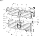
- FIG 1 represents the front part of the engine compartment of a motor vehicle comprising a controlled regulation device for the flow of incoming cooling air 1 according to the invention inserted longitudinally between the front bumper beam 2 and the various heat exchangers 3, 4, 5 that this vehicle comprises (namely and from rear to front, the radiator 3 of the cooling circuit of the thermal engine, the condenser 4 of the air conditioning system circuit, and finally the radiator 5 for cooling the battery of the hybrid electric motor).
- the controlled regulation device for the flow of incoming cooling air 1 comprises two regulation modules 10, 20 located respectively above and below the front bumper beam 2, opposite the upper and lower air inlets of the vehicle.
- the first regulation module 10 comprises a rectangular support locker 11 delimiting two side boxes of identical widths 11A, 11B, extending symmetrically on either side of a central box 11C of narrower width.
- the first regulation module 10 further comprises a first control mechanism 14 located at the central box 11C, in front of the internal ends of the flaps 12, 13.
- This first control mechanism 14 comprises a connecting rod 14A articulated to the three flaps 12 along transverse axes offset from their pivot axes, so as to make them rotationally integral with each other, as well as a connecting rod 14B articulated to the three flaps 13 along transverse axes offset from their pivot axes, so as to make them rotationally integral with each other.
- This second control mechanism 24 comprises a connecting member 25 located in front of the internal ends of the flaps 22, 23, as well as a hinge plate 26 housed in the central box 21C and visible in the figure1 .
- the piloted regulation device 1 also comprises a T-shaped connecting rod 30 connecting the first and second control mechanisms 14, 24 to each other.
- the rod 30 consists of a head 31 articulated to the first control mechanism 14, a foot 32 articulated to the second control mechanism control 24, and a jamb 33 extending vertically between the head 31 and the foot 32.
- the head 31 extends transversely in front of the two connecting rods 14A, 14B of the first control mechanism 14 and its two lateral ends are mounted pivotally articulated along the same transverse axis on these two connecting rods 14A, 14B, so that all of the flaps 12, 13 of the first regulation module 10 are integral in rotation (see figure 3 ).
- the foot 32 is in the form of a finger extending in the extension of the jamb 33 and carrying at its free end a transverse pin 32A mounted articulated to slide and pivot through an arc-shaped light 26A formed in the plate 26 (see figure 4 ).
- this connecting rod 30 has a first oblong recess 34 formed in the upper portion of the slanted section 33A and extending at the level of the head 31, as well as a second oblong recess 35 formed in the section 33B of the leg 33.
- the piloted regulation device 1 finally comprises an actuator 40 housed in the central box 11C of the first regulation module 10.
- this actuator 40 comprises a housing 41 housing an electric motor (not shown and for example of the stepper or direct current type) provided with a hollow rotating shaft 42 in which is inserted by shape correspondence the internal end of a flap 12 of the first regulation module 10 passing through said housing 41, so that this flap 12 is integral in rotation with this shaft 42.
- the flaps 12, 13 of the first regulation module 10 being integral in rotation by means of the first control mechanism 14, it is understood that the rotation of the shaft 42 in one direction or the other causes the rotation of these shutters 12, 13 from an open position to a closed position or vice versa.
- the first frangible weakening zone 36 is arranged on the upper slanted section 33A of this leg 33, advantageously at a height located between the lower end of the first regulation module 10 and the upper end of the front bumper beam 2.
- the second frangible weakening zone 37 is arranged on the vertical lower section 33B of this leg 33, advantageously at a height located between the upper end of the second regulation module 20 and the lower end of the front bumper beam 2.
- the resistance to shear stress of these necking lines 36, 37 can be adjusted by varying their thickness which will for example be between 1 and 1.5 mm for a general thickness of the rod 30 between 2 and 2.5 mm.
- the rod 30 may be devoid of the second frangible weakening zone 37.
- the frangible weakening zone(s) may be shaped differently.
- these may be provided with initiator holes distributed at regular intervals along their length so as to facilitate their rupture.
- control mechanism of each regulation module can vary, as can the number of shutters it comprises.
Landscapes
- Engineering & Computer Science (AREA)
- Chemical & Material Sciences (AREA)
- Combustion & Propulsion (AREA)
- Transportation (AREA)
- Mechanical Engineering (AREA)
- Cooling, Air Intake And Gas Exhaust, And Fuel Tank Arrangements In Propulsion Units (AREA)
Claims (10)
- Steuerbare Steuervorrichtung für den Kühleingangsluftstrom (1) für ein Kraftfahrzeug, die zwischen dem vorderen Stoßfängerbalken (2) und mindestens einem Wärmetauscher (3, 4, 5) des Fahrzeugs angeordnet ist, wobei die Vorrichtung (1) ein erstes und ein zweites Steuermodul (10, 20) aufweist, die jeweils oberhalb und unterhalb des Balkens (2) gegenüber dem oberen und unteren Lufteinlass des Fahrzeugs angeordnet sind, wobei jedes Modul (10, 20) ein Traggestell (11, 21) aufweist, das zwei seitliche Kästen begrenzt (11A, 11B, 21A, 21B), die durch ein zentrales Feld (11C, 21C) getrennt sind, eine Vielzahl von Klappen (12, 13, 22, 23), die in den seitlichen Feldern (11A, 11B, 21A, 21B) angeordnet sind und um parallele Querachsen zwischen einer Verschlussposition und einer Öffnungsposition schwenkbar gelagert sind, sowie einen Steuermechanismus (14, 24), der an dem zentralen Feld (11C, 21C) angebracht ist und mit den Klappen (12, 13, 22, 23) gelenkig verbunden ist, wobei die Vorrichtung (1) außerdem eine Verbindungsstange (30) aufweist, die die Betätigungsmechanismen (14, 24) der Module (10, 20) verbindet, sowie ein Stellglied (40), das in dem mittleren Gehäuse (11C) eines Moduls (11) untergebracht ist, wobei das Stellglied (40) in der Lage ist, das Schwenken aller Klappen (12, 13, 22, 23) der Module (10) zu bewirken, 20) über die Steuermechanismen (14, 24) und die Verbindungsstange (30);
das Merkmal ist, dass die Verbindungsstange (30) wenigstens eine zerbrechliche Schwächungszone geringeren Widerstands (36, 37) aufweist, die so konfiguriert ist, dass sie unter einer vorbestimmten Längsscherspannung bricht. - Vorrichtung nach Anspruch 1, dadurch gekennzeichnet, dass jeder wenigstens genannte zerbrechliche Schwächungsbereich die Form einer Querstreckungslinie (36, 37) hat, die aus einer Verdünnungsnut besteht, die auf der Vorderseite der Verbindungsstange (30) ausgebildet ist.
- Vorrichtung nach einem der Ansprüche 1 oder 2, dadurch gekennzeichnet, dass die Verbindungsstange (30) einen Kopf (31), der an dem Steuermechanismus (14) des ersten Regelungsmoduls (10) angelenkt ist, einen Fuß (32), der an dem Steuermechanismus (24) des zweiten Regelungsmoduls (20) angelenkt ist, und einen Fuß (33) aufweist, der sich vertikal zwischen dem Kopf (31) und dem Fuß (32) erstreckt.
- Vorrichtung nach Anspruch 3, dadurch gekennzeichnet, dass der Schenkel (33) einen oberen Abschnitt (33A), der sich schräg nach unten und nach hinten von dem Kopf (31) erstreckt, sowie einen unteren Abschnitt (33B) aufweist, der sich vertikal nach unten in der Verlängerung des oberen Abschnitts (33A) zu dem Fuß (32) erstreckt.
- Vorrichtung nach Anspruch 4, dadurch gekennzeichnet, dass die Stange (30) eine erste zerbrechliche Schwächungszone (36) aufweist, die auf dem oberen schrägen Abschnitt (33A) des Schenkels (33) angeordnet ist.
- Vorrichtung nach Anspruch 5, dadurch gekennzeichnet, dass der erste zerbrechliche Schwächungsbereich (36) in der Höhe zwischen dem unteren Ende des ersten Regelmoduls (10) und dem oberen Ende des Stoßfängerträgers (2) angeordnet ist.
- Vorrichtung nach einem der Ansprüche 5 oder 6, dadurch gekennzeichnet, dass die Stange (30) eine zweite so genannte zerbrechliche Schwächungszone (37) aufweist, die auf dem unteren vertikalen Abschnitt (33B) des Unterschenkels (33) angeordnet ist.
- Vorrichtung nach Anspruch 7, dadurch gekennzeichnet, dass der zweite zerbrechliche Schwächungsbereich (37) in der Höhe zwischen dem oberen Ende des zweiten Regelmoduls (20) und dem unteren Ende des Stoßfängerträgers (2) angeordnet ist.
- Vorrichtung nach einem der Ansprüche 1 bis 8, dadurch gekennzeichnet, dass die Verbindungsstange (30) einstückig aus einem thermoplastischen Material geformt ist.
- Kraftfahrzeug mit einem vorderen Stoßfängerbalken (2), mindestens einem Wärmetauscher (3, 4, 5) und einer zwischen dem vorderen Stoßfängerbalken (2) und dem mindestens einen Wärmetauscher (3, 4, 5) angeordneten steuerbaren Steuervorrichtung für den Kühleingangsluftstrom (1); dadurch gekennzeichnet, dass die steuerbare Steuervorrichtung für den Kühleingangsluftstrom (1) einem der Ansprüche 1 bis 9 entspricht.
Applications Claiming Priority (2)
| Application Number | Priority Date | Filing Date | Title |
|---|---|---|---|
| FR2105022A FR3122849B1 (fr) | 2021-05-12 | 2021-05-12 | Dispositif de régulation pilotée du flux d’air entrant de refroidissement d’un véhicule automobile |
| PCT/FR2022/050531 WO2022238629A1 (fr) | 2021-05-12 | 2022-03-23 | Dispositif de régulation pilotée du flux d'air entrant de refroidissement d'un véhicule automobile |
Publications (2)
| Publication Number | Publication Date |
|---|---|
| EP4337485A1 EP4337485A1 (de) | 2024-03-20 |
| EP4337485B1 true EP4337485B1 (de) | 2025-03-05 |
Family
ID=77180118
Family Applications (1)
| Application Number | Title | Priority Date | Filing Date |
|---|---|---|---|
| EP22717219.4A Active EP4337485B1 (de) | 2021-05-12 | 2022-03-23 | Vorrichtung zur geregelten regelung des zuluftstroms einer kraftfahrzeug-kühlluftanlage |
Country Status (3)
| Country | Link |
|---|---|
| EP (1) | EP4337485B1 (de) |
| FR (1) | FR3122849B1 (de) |
| WO (1) | WO2022238629A1 (de) |
Family Cites Families (4)
| Publication number | Priority date | Publication date | Assignee | Title |
|---|---|---|---|---|
| FR2105022B1 (de) | 1970-09-08 | 1973-11-16 | Faure Roger | |
| JP2010223150A (ja) | 2009-03-25 | 2010-10-07 | Aisin Seiki Co Ltd | 車両用可動グリルシャッタ |
| EP3002145B1 (de) * | 2014-09-30 | 2017-10-18 | Faltec Company Limited | Fahrzeugrillblende, fahrzeugklappenelement und aktuator |
| FR3040661B1 (fr) * | 2015-09-03 | 2018-10-26 | Valeo Systemes Thermiques | Module de face avant comportant un guide d'air deformable pour vehicule automobile |
-
2021
- 2021-05-12 FR FR2105022A patent/FR3122849B1/fr active Active
-
2022
- 2022-03-23 WO PCT/FR2022/050531 patent/WO2022238629A1/fr not_active Ceased
- 2022-03-23 EP EP22717219.4A patent/EP4337485B1/de active Active
Also Published As
| Publication number | Publication date |
|---|---|
| FR3122849B1 (fr) | 2023-03-31 |
| EP4337485A1 (de) | 2024-03-20 |
| WO2022238629A1 (fr) | 2022-11-17 |
| FR3122849A1 (fr) | 2022-11-18 |
Similar Documents
| Publication | Publication Date | Title |
|---|---|---|
| EP0970854B1 (de) | Vorrichtung zur Befestigung der Seitenschenkel einer Stossstange auf einem Fahrzeugkarosserie-Kotflügel | |
| EP3634800B1 (de) | Vorrichtung zum verschliessen eines lufteinlasses eines kraftfahrzeugs und verfahren zur herstellung einer solchen verschlussvorrichtung | |
| WO2022200168A1 (fr) | Module de refroidissement pour vehicule automobile electrique ou hybride | |
| WO2019002727A1 (fr) | Dispositif d'obturation d'entrée d'air de face avant de véhicule automobile | |
| EP0605325A1 (de) | Vorrichtung zur Regelierung eines Luftstroms in einer Luftführung, insbesondere für einen Kühler eines Kraftfahrzeuges | |
| EP4337485B1 (de) | Vorrichtung zur geregelten regelung des zuluftstroms einer kraftfahrzeug-kühlluftanlage | |
| EP3359406B1 (de) | Frontendmodulträger und zugehöriges frontendmodul | |
| EP3571080B1 (de) | Vorrichtung zum abdichten eines frontseitigen lufteinlasses eines kraftfahrzeugs und verfahren zur herstellung davon | |
| EP4314511A1 (de) | Kühlmodul für ein elektro- oder hybridfahrzeug | |
| FR3038550A1 (fr) | Panneau d’entree d’air avec commande a biellettes et ressort | |
| FR3120022A1 (fr) | Module d’entrée d’air pilotée avec zone d’absorption de chocs | |
| FR3112103A1 (fr) | véhicule possédant une façade avant dotée d’une pièce de structure multifonction | |
| EP4334152B1 (de) | Extrudierte klappe für eine vorrichtung zum absperren eines lufteinlasses einer kraftfahrzeugvorderseite | |
| EP2736793B1 (de) | Kopfmodul für ein kraftfahrzeug | |
| EP4347293B1 (de) | Für die aufprallreparatur optimierte vorrichtung zur gesteuerten regelung des in ein fahrzeug strömenden luftstroms | |
| EP4240607A1 (de) | Kühlmodul für ein elektro- oder hybridkraftfahrzeug mit einer tangentialflussturbomaschine | |
| FR3061876A1 (fr) | Dispositif d’obturation d’entree d’air de face avant de vehicule automobile et procede de fabrication | |
| FR3040662A1 (fr) | Dispositif d'obturation d'entree d'air de face avant de vehicule automobile et module de face avant pour vehicule automobile | |
| EP4225600B1 (de) | Vorrichtung zum absperren eines luftstroms für eine kraftfahrzeugfront mit mehreren stützrahmen | |
| FR3117950A1 (fr) | Dispositif d’obturation de flux d’air de face avant de véhicule automobile comportant plusieurs cadres supports | |
| WO2018134493A1 (fr) | Dispositif d'obturation d'entree d'air de face avant de vehicule automobile | |
| WO2022200166A1 (fr) | Module de refroidissement pour vehicule automobile electrique ou hybride a turbomachine tangentielle | |
| EP4225601A1 (de) | Verschlussvorrichtung für einen frontluftstrom eines kraftfahrzeugs mit einem blendenverschlusssystem | |
| FR3147519A1 (fr) | Entrée d’air pilotée de véhicule automobile | |
| EP4499432A1 (de) | Luftführung für eine kraftfahrzeugkühlvorrichtung mit einer runden vorderen oberen kante für fussgängeraufprall |
Legal Events
| Date | Code | Title | Description |
|---|---|---|---|
| STAA | Information on the status of an ep patent application or granted ep patent |
Free format text: STATUS: UNKNOWN |
|
| STAA | Information on the status of an ep patent application or granted ep patent |
Free format text: STATUS: THE INTERNATIONAL PUBLICATION HAS BEEN MADE |
|
| PUAI | Public reference made under article 153(3) epc to a published international application that has entered the european phase |
Free format text: ORIGINAL CODE: 0009012 |
|
| STAA | Information on the status of an ep patent application or granted ep patent |
Free format text: STATUS: REQUEST FOR EXAMINATION WAS MADE |
|
| 17P | Request for examination filed |
Effective date: 20231117 |
|
| AK | Designated contracting states |
Kind code of ref document: A1 Designated state(s): AL AT BE BG CH CY CZ DE DK EE ES FI FR GB GR HR HU IE IS IT LI LT LU LV MC MK MT NL NO PL PT RO RS SE SI SK SM TR |
|
| DAV | Request for validation of the european patent (deleted) | ||
| DAX | Request for extension of the european patent (deleted) | ||
| GRAP | Despatch of communication of intention to grant a patent |
Free format text: ORIGINAL CODE: EPIDOSNIGR1 |
|
| STAA | Information on the status of an ep patent application or granted ep patent |
Free format text: STATUS: GRANT OF PATENT IS INTENDED |
|
| INTG | Intention to grant announced |
Effective date: 20241106 |
|
| GRAS | Grant fee paid |
Free format text: ORIGINAL CODE: EPIDOSNIGR3 |
|
| GRAA | (expected) grant |
Free format text: ORIGINAL CODE: 0009210 |
|
| STAA | Information on the status of an ep patent application or granted ep patent |
Free format text: STATUS: THE PATENT HAS BEEN GRANTED |
|
| AK | Designated contracting states |
Kind code of ref document: B1 Designated state(s): AL AT BE BG CH CY CZ DE DK EE ES FI FR GB GR HR HU IE IS IT LI LT LU LV MC MK MT NL NO PL PT RO RS SE SI SK SM TR |
|
| REG | Reference to a national code |
Ref country code: GB Ref legal event code: FG4D Free format text: NOT ENGLISH |
|
| REG | Reference to a national code |
Ref country code: CH Ref legal event code: EP |
|
| REG | Reference to a national code |
Ref country code: DE Ref legal event code: R084 Ref document number: 602022011451 Country of ref document: DE Ref country code: IE Ref legal event code: FG4D Free format text: LANGUAGE OF EP DOCUMENT: FRENCH |
|
| REG | Reference to a national code |
Ref country code: DE Ref legal event code: R096 Ref document number: 602022011451 Country of ref document: DE |
|
| PGFP | Annual fee paid to national office [announced via postgrant information from national office to epo] |
Ref country code: AT Payment date: 20250417 Year of fee payment: 4 |
|
| PG25 | Lapsed in a contracting state [announced via postgrant information from national office to epo] |
Ref country code: RS Free format text: LAPSE BECAUSE OF FAILURE TO SUBMIT A TRANSLATION OF THE DESCRIPTION OR TO PAY THE FEE WITHIN THE PRESCRIBED TIME-LIMIT Effective date: 20250605 |
|
| PG25 | Lapsed in a contracting state [announced via postgrant information from national office to epo] |
Ref country code: FI Free format text: LAPSE BECAUSE OF FAILURE TO SUBMIT A TRANSLATION OF THE DESCRIPTION OR TO PAY THE FEE WITHIN THE PRESCRIBED TIME-LIMIT Effective date: 20250305 |
|
| REG | Reference to a national code |
Ref country code: NL Ref legal event code: MP Effective date: 20250305 |
|
| PG25 | Lapsed in a contracting state [announced via postgrant information from national office to epo] |
Ref country code: ES Free format text: LAPSE BECAUSE OF FAILURE TO SUBMIT A TRANSLATION OF THE DESCRIPTION OR TO PAY THE FEE WITHIN THE PRESCRIBED TIME-LIMIT Effective date: 20250305 |
|
| REG | Reference to a national code |
Ref country code: LT Ref legal event code: MG9D |
|
| PG25 | Lapsed in a contracting state [announced via postgrant information from national office to epo] |
Ref country code: NO Free format text: LAPSE BECAUSE OF FAILURE TO SUBMIT A TRANSLATION OF THE DESCRIPTION OR TO PAY THE FEE WITHIN THE PRESCRIBED TIME-LIMIT Effective date: 20250605 |
|
| PG25 | Lapsed in a contracting state [announced via postgrant information from national office to epo] |
Ref country code: HR Free format text: LAPSE BECAUSE OF FAILURE TO SUBMIT A TRANSLATION OF THE DESCRIPTION OR TO PAY THE FEE WITHIN THE PRESCRIBED TIME-LIMIT Effective date: 20250305 |
|
| PG25 | Lapsed in a contracting state [announced via postgrant information from national office to epo] |
Ref country code: LV Free format text: LAPSE BECAUSE OF FAILURE TO SUBMIT A TRANSLATION OF THE DESCRIPTION OR TO PAY THE FEE WITHIN THE PRESCRIBED TIME-LIMIT Effective date: 20250305 |
|
| PG25 | Lapsed in a contracting state [announced via postgrant information from national office to epo] |
Ref country code: BG Free format text: LAPSE BECAUSE OF FAILURE TO SUBMIT A TRANSLATION OF THE DESCRIPTION OR TO PAY THE FEE WITHIN THE PRESCRIBED TIME-LIMIT Effective date: 20250305 Ref country code: GR Free format text: LAPSE BECAUSE OF FAILURE TO SUBMIT A TRANSLATION OF THE DESCRIPTION OR TO PAY THE FEE WITHIN THE PRESCRIBED TIME-LIMIT Effective date: 20250606 |
|
| PG25 | Lapsed in a contracting state [announced via postgrant information from national office to epo] |
Ref country code: AT Free format text: LAPSE BECAUSE OF FAILURE TO SUBMIT A TRANSLATION OF THE DESCRIPTION OR TO PAY THE FEE WITHIN THE PRESCRIBED TIME-LIMIT Effective date: 20250305 |
|
| REG | Reference to a national code |
Ref country code: AT Ref legal event code: MK05 Ref document number: 1772644 Country of ref document: AT Kind code of ref document: T Effective date: 20250305 |
|
| PG25 | Lapsed in a contracting state [announced via postgrant information from national office to epo] |
Ref country code: NL Free format text: LAPSE BECAUSE OF FAILURE TO SUBMIT A TRANSLATION OF THE DESCRIPTION OR TO PAY THE FEE WITHIN THE PRESCRIBED TIME-LIMIT Effective date: 20250305 |
|
| PG25 | Lapsed in a contracting state [announced via postgrant information from national office to epo] |
Ref country code: SE Free format text: LAPSE BECAUSE OF FAILURE TO SUBMIT A TRANSLATION OF THE DESCRIPTION OR TO PAY THE FEE WITHIN THE PRESCRIBED TIME-LIMIT Effective date: 20250305 |
|
| PG25 | Lapsed in a contracting state [announced via postgrant information from national office to epo] |
Ref country code: SM Free format text: LAPSE BECAUSE OF FAILURE TO SUBMIT A TRANSLATION OF THE DESCRIPTION OR TO PAY THE FEE WITHIN THE PRESCRIBED TIME-LIMIT Effective date: 20250305 |
|
| PG25 | Lapsed in a contracting state [announced via postgrant information from national office to epo] |
Ref country code: PT Free format text: LAPSE BECAUSE OF FAILURE TO SUBMIT A TRANSLATION OF THE DESCRIPTION OR TO PAY THE FEE WITHIN THE PRESCRIBED TIME-LIMIT Effective date: 20250707 |
|
| PG25 | Lapsed in a contracting state [announced via postgrant information from national office to epo] |
Ref country code: IT Free format text: LAPSE BECAUSE OF FAILURE TO SUBMIT A TRANSLATION OF THE DESCRIPTION OR TO PAY THE FEE WITHIN THE PRESCRIBED TIME-LIMIT Effective date: 20250305 Ref country code: PL Free format text: LAPSE BECAUSE OF FAILURE TO SUBMIT A TRANSLATION OF THE DESCRIPTION OR TO PAY THE FEE WITHIN THE PRESCRIBED TIME-LIMIT Effective date: 20250305 |
|
| PG25 | Lapsed in a contracting state [announced via postgrant information from national office to epo] |
Ref country code: EE Free format text: LAPSE BECAUSE OF FAILURE TO SUBMIT A TRANSLATION OF THE DESCRIPTION OR TO PAY THE FEE WITHIN THE PRESCRIBED TIME-LIMIT Effective date: 20250305 Ref country code: CZ Free format text: LAPSE BECAUSE OF FAILURE TO SUBMIT A TRANSLATION OF THE DESCRIPTION OR TO PAY THE FEE WITHIN THE PRESCRIBED TIME-LIMIT Effective date: 20250305 |
|
| PG25 | Lapsed in a contracting state [announced via postgrant information from national office to epo] |
Ref country code: RO Free format text: LAPSE BECAUSE OF FAILURE TO SUBMIT A TRANSLATION OF THE DESCRIPTION OR TO PAY THE FEE WITHIN THE PRESCRIBED TIME-LIMIT Effective date: 20250305 |
|
| REG | Reference to a national code |
Ref country code: CH Ref legal event code: H13 Free format text: ST27 STATUS EVENT CODE: U-0-0-H10-H13 (AS PROVIDED BY THE NATIONAL OFFICE) Effective date: 20251023 |
|
| PG25 | Lapsed in a contracting state [announced via postgrant information from national office to epo] |
Ref country code: SK Free format text: LAPSE BECAUSE OF FAILURE TO SUBMIT A TRANSLATION OF THE DESCRIPTION OR TO PAY THE FEE WITHIN THE PRESCRIBED TIME-LIMIT Effective date: 20250305 |
|
| PG25 | Lapsed in a contracting state [announced via postgrant information from national office to epo] |
Ref country code: IS Free format text: LAPSE BECAUSE OF FAILURE TO SUBMIT A TRANSLATION OF THE DESCRIPTION OR TO PAY THE FEE WITHIN THE PRESCRIBED TIME-LIMIT Effective date: 20250705 |
|
| PG25 | Lapsed in a contracting state [announced via postgrant information from national office to epo] |
Ref country code: LU Free format text: LAPSE BECAUSE OF NON-PAYMENT OF DUE FEES Effective date: 20250323 |
|
| REG | Reference to a national code |
Ref country code: DE Ref legal event code: R097 Ref document number: 602022011451 Country of ref document: DE |
|
| REG | Reference to a national code |
Ref country code: BE Ref legal event code: MM Effective date: 20250331 |
|
| PG25 | Lapsed in a contracting state [announced via postgrant information from national office to epo] |
Ref country code: MC Free format text: LAPSE BECAUSE OF FAILURE TO SUBMIT A TRANSLATION OF THE DESCRIPTION OR TO PAY THE FEE WITHIN THE PRESCRIBED TIME-LIMIT Effective date: 20250305 |
|
| PLBE | No opposition filed within time limit |
Free format text: ORIGINAL CODE: 0009261 |
|
| STAA | Information on the status of an ep patent application or granted ep patent |
Free format text: STATUS: NO OPPOSITION FILED WITHIN TIME LIMIT |
|
| PG25 | Lapsed in a contracting state [announced via postgrant information from national office to epo] |
Ref country code: DK Free format text: LAPSE BECAUSE OF FAILURE TO SUBMIT A TRANSLATION OF THE DESCRIPTION OR TO PAY THE FEE WITHIN THE PRESCRIBED TIME-LIMIT Effective date: 20250305 |
|
| REG | Reference to a national code |
Ref country code: CH Ref legal event code: L10 Free format text: ST27 STATUS EVENT CODE: U-0-0-L10-L00 (AS PROVIDED BY THE NATIONAL OFFICE) Effective date: 20260114 |
|
| PG25 | Lapsed in a contracting state [announced via postgrant information from national office to epo] |
Ref country code: BE Free format text: LAPSE BECAUSE OF NON-PAYMENT OF DUE FEES Effective date: 20250331 |
|
| PG25 | Lapsed in a contracting state [announced via postgrant information from national office to epo] |
Ref country code: CH Free format text: LAPSE BECAUSE OF NON-PAYMENT OF DUE FEES Effective date: 20250331 |
|
| PG25 | Lapsed in a contracting state [announced via postgrant information from national office to epo] |
Ref country code: IE Free format text: LAPSE BECAUSE OF NON-PAYMENT OF DUE FEES Effective date: 20250323 |
|
| 26N | No opposition filed |
Effective date: 20251208 |
|
| PGFP | Annual fee paid to national office [announced via postgrant information from national office to epo] |
Ref country code: DE Payment date: 20260219 Year of fee payment: 5 |
|
| PGFP | Annual fee paid to national office [announced via postgrant information from national office to epo] |
Ref country code: FR Payment date: 20260220 Year of fee payment: 5 |