EP4337067B1 - Maschine und verfahren zum kochen von lebensmitteln - Google Patents
Maschine und verfahren zum kochen von lebensmitteln Download PDFInfo
- Publication number
- EP4337067B1 EP4337067B1 EP22727988.2A EP22727988A EP4337067B1 EP 4337067 B1 EP4337067 B1 EP 4337067B1 EP 22727988 A EP22727988 A EP 22727988A EP 4337067 B1 EP4337067 B1 EP 4337067B1
- Authority
- EP
- European Patent Office
- Prior art keywords
- opening
- solenoid valve
- container
- hot water
- supply
- Prior art date
- Legal status (The legal status is an assumption and is not a legal conclusion. Google has not performed a legal analysis and makes no representation as to the accuracy of the status listed.)
- Active
Links
Images
Classifications
-
- A—HUMAN NECESSITIES
- A47—FURNITURE; DOMESTIC ARTICLES OR APPLIANCES; COFFEE MILLS; SPICE MILLS; SUCTION CLEANERS IN GENERAL
- A47J—KITCHEN EQUIPMENT; COFFEE MILLS; SPICE MILLS; APPARATUS FOR MAKING BEVERAGES
- A47J27/00—Cooking-vessels
- A47J27/04—Cooking-vessels for cooking food in steam; Devices for extracting fruit juice by means of steam ; Vacuum cooking vessels
-
- A—HUMAN NECESSITIES
- A47—FURNITURE; DOMESTIC ARTICLES OR APPLIANCES; COFFEE MILLS; SPICE MILLS; SUCTION CLEANERS IN GENERAL
- A47J—KITCHEN EQUIPMENT; COFFEE MILLS; SPICE MILLS; APPARATUS FOR MAKING BEVERAGES
- A47J27/00—Cooking-vessels
- A47J2027/006—Cooking-vessels especially adapted for preparing pasta
-
- A—HUMAN NECESSITIES
- A47—FURNITURE; DOMESTIC ARTICLES OR APPLIANCES; COFFEE MILLS; SPICE MILLS; SUCTION CLEANERS IN GENERAL
- A47J—KITCHEN EQUIPMENT; COFFEE MILLS; SPICE MILLS; APPARATUS FOR MAKING BEVERAGES
- A47J27/00—Cooking-vessels
- A47J27/04—Cooking-vessels for cooking food in steam; Devices for extracting fruit juice by means of steam ; Vacuum cooking vessels
- A47J2027/043—Cooking-vessels for cooking food in steam; Devices for extracting fruit juice by means of steam ; Vacuum cooking vessels for cooking food in steam
Definitions
- the present invention relates to a machine and to a method for cooking food.
- the present invention relates to a machine and to a method for cooking food by means of the supply of hot water and steam.
- Patent applications No. WO 2019/207509 , No. WO 2020/212909 and No. WO 2020/212207 of the applicant teach how to cook fresh food contained in a container by means of the supply of hot water and steam into the container containing the food.
- Document KR 20170109203 discloses a further example of an apparatus for heating and cooking food.
- the cooking of fresh food by means of water and steam requires dosing the steam and the hot water so as to cook the food quickly. At the same time, it is necessary to reach high qualitative levels with regard to the cooking of the food and prevent the presence of water on the bottom of the container so as to meet the customer's expectations both in terms of taste and in terms of product presentation.
- the present invention it is possible to automatically and quickly prepare a plurality of different recipes associated with respective cooking programs, container so as to meet the customer's expectations both in terms of taste and in terms of product presentation.
- the object of the present invention is to provide a machine for cooking food which manages to conciliate the above-described requirements in a simple and cost-effective manner.
- a machine for cooking food according to claim 1 is provided. dispensing in an independent manner steam and hot water inside the container.
- the control of the time of the steam supply and of the volume of water to be dispensed into the container allows implementing each cooking program in a simple and effective manner.
- first solenoid valve and the second solenoid valve are on-off type.
- control unit is configured to close in sequence the second solenoid valve and, after a given time interval, the first solenoid valve, so as to interrupt the hot water supply in advance with respect to the end of the steam supply.
- control unit is configured to control the first solenoid valve so as to supply steam to the first opening at intervals.
- control unit is configured to control the second solenoid valve so as to supply hot water to the second opening at intervals.
- control unit comprises a user interface configured to select a cooking program from a plurality of cooking programs related to respective recipes; the control unit being configured to control the first and the second solenoid valves depending on the selected cooking program so as to prepare the desired recipe.
- control unit is configured to emit an authorization signal for opening the container and for removing the container from the machine.
- the user interface is configured to set cooking programs depending on respective recipes.
- the user interface is configured to select the time of the steam supply, and/or the steam supply intervals, and/or the volume of hot water to be dispensed, and/or the hot water supply intervals, and/or the delay of the water supply with respect to the steam supply, and/or the delay of the opening of the container with respect to the closing of the first solenoid valve.
- a further object of the present invention is to provide a method for cooking food according to claim 8, which allows mitigating the drawbacks of the prior art.
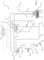
- reference numeral 1 indicates, as a whole, a machine for cooking food 2 in a container 3 containing said food 2.
- the machine 1 can be used in public catering places (for example coffee bars, restaurants, diners etc.) or at home.
- the food 2 contained in the container 3 can be a dose of raw pasta or a sauce for said dose of pasta.
- the machine 1 comprises a dispenser 4 configured to be arranged over the container 3 and to close the container 3 and comprising at least one opening 5 for dispensing steam into the container 3 and at least one opening 6 for dispensing hot water into the container 3; a duct 7 and a solenoid valve 8, for supplying steam to the opening 5; a duct 9 and a solenoid valve 10 for supplying hot water to the opening 6; and a control unit 11 configured to control the opening and the closing of the solenoid valves 8 and 10 so as to modulate the time of the steam supply and the volume of water depending on a selected cooking program.
- the solenoid valves 8 and 10 are on-off type.
- the machine 1 comprises a boiler 12, which is configured to provide steam and is connected to the duct 7; a boiler 13, which is configured to provide hot water and is connected to the duct 9; and a duct 14 and a solenoid valve 15 of on-off type for supplying hot water from the boiler 13 to the boiler 12.
- each boiler 12, 13 comprises electric resistors, not shown in the accompanying figures, for adjusting the quantity of heat provided and, consequently, the steam temperature and the hot water temperature, respectively.
- the boiler 12 is configured to heat the steam at a temperature ranging between approximately 105 °C and approximately 135 °C
- the boiler 13 is configured to heat the hot water at a temperature ranging between approximately 90 °C and approximately 105 °C.
- the machine 1 comprises a duct 16 for supplying hot water from the boiler 13 to a discharge 17, and a safety valve 18, which is coupled to the boiler 13, is in fluidic communication with the duct 16 and is configured to allow the passage of hot water in the duct 16 in case the pressure inside the boiler 13 exceeds a given threshold.
- the machine 1 comprises a duct 19 for supplying steam from the boiler 12 to the discharge 17, and a safety valve 20, which is coupled to the boiler 12, is in fluidic communication with the duct 19 and is configured to allow the passage of steam in the duct 19 in case the pressure inside the boiler 12 exceeds a given threshold.
- the machine 1 comprises a duct 21 for supplying discharge water from the boiler 12 to the discharge 17, and a solenoid valve 22 of on-off type configured to control the supply of discharge water to the discharge 17 along the duct 21.
- the machine 1 comprises a temperature sensor 23, which is configured to emit a first temperature signal related to the temperature of the steam in the boiler 12; and a temperature sensor 24, which is configured to emit a second temperature signal related to the temperature of the hot water in the boiler 13.
- the machine 1 comprises a level probe 25, which is associated with the boiler 12 and is configured to emit a level signal related to the level of water in the boiler 12.
- the machine 1 comprises a connection 26 to a water supply network, which ensures an almost unlimited supply of water at ambient temperature; a duct 27 for supplying water at ambient temperature from the connection 26 to the boiler 13; a solenoid valve 28 of on-off type for controlling the supply of water at ambient temperature along the duct 27; a pump 29, which is configured to provide a head sufficient for allowing the flow of the water inside the machine 1; and a flow-rate meter 30, preferably a flowmeter, which is configured to emit a flow-rate signal related to the flow-rate of the water running in the duct 27.
- the machine 1 comprises, in alternative to the connection 26, a tank, which is configured to contain water at ambient temperature and is fluidically connected to the duct 27.
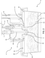
- the container 3 comprises a base wall 31, preferably having a circular shape; a side wall 32, preferably slightly flared, provided with an upper edge 33; and an opening 34, preferably having a circular shape, opposite the base wall 31.
- the dispenser 4 comprises a central body 35 provided with a steam supply channel 36, which is in fluidic communication with the duct 7 and with the openings 5, and with a hot water supply channel 37, which is in fluidic communication with the duct 9 and with the openings 6; and a lid 38, which is arranged around the central body 35 and is configured to close the opening 34 of the container 3 so as to form a substantially closed cooking compartment for the cooking of the food 2.
- the central body 35 comprises a central protrusion 39, which is provided with the openings 5; and an annular wall 40, which extends around the central protrusion 39 and is provided with the openings 6.
- the machine 1 comprises a duct 41, which is configured to evacuate steam from the container 3 and is connected to a steam discharge 42.
- the duct 41 extends through the lid 38 so as to put the inside of the cooking compartment in fluidic communication with the steam discharge 42.
- the control unit 11 comprises a user interface 43 configured to allow the selection of a cooking program from a plurality of cooking programs related to respective recipes.
- the control unit 11 is configured to control the solenoid valves 8 and 10 depending on a selected cooking program.
- control unit 11 is configured to receive the signals emitted by the temperature sensors 23 and 24, by the level probe 25 and by the flow-rate meter 30 and to control the solenoid valves 8, 10 and 15 depending on the signals received from the temperature sensors 23 and 24, from the level probe 25 and from the flow-rate meter 30.
- the user interface 43 comprises a touch-screen panel, not shown in the accompanying figures, by means of which an operator can view and manually select a desired recipe.
- control unit 11 comprises a storage 44, in which a plurality of recipes is stored. Each recipe is associated with a plurality of cooking parameters which define a given cooking program.
- the user interface 43 is configured to allow an operator to set said cooking programs and to store said cooking programs in the storage 44.
- the plurality of cooking parameters comprises the time of the steam supply, and/or the steam supply intervals, and/or the volume of hot water to be dispensed, and/or the hot water supply intervals, and/or the delay of the hot water supply with respect to the steam supply, and/or the delay of the opening of the container 3 with respect to the closing of the solenoid valve 8, and/or the flow-rate of hot water to be dispensed inside the container 3.
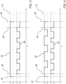
- a graph is shown of an opening and closing state 45 of the solenoid valve 8 and of an opening and closing state 46 of the solenoid valve 10 in a particular operational configuration of the machine 1. More specifically, the graph of Figure 3 is a cartesian plane wherein the abscissa axis represents the time and the ordinate axis represents the opening/closing states 45 and 46 of the solenoid valves 8 and 10, each of which can assume the value 0 (closed solenoid valves 8 and 10) or the value 1 (open solenoid valves 8 and 10).
- the solenoid valves 8 and 10 are open, steam and hot water are dispensed inside the container 3.
- the solenoid valves 8 and 10 are closed the supply of steam and hot water inside the container 3 is interrupted.
- control unit 11 is configured to control the state 45 of the solenoid valve 8 so as to supply in a continuous manner steam to the openings 5 and to control the state 46 of the solenoid valve 10 so as to supply hot water to the openings 6 at intervals.
- the control unit 11 is configured to determine the delay of the hot water supply with respect to the steam supply. In such circumstance, the control unit 11 is configured to control the opening of the solenoid valve 8 at a time instant 47 and to control the opening of the solenoid valve 10 at a subsequent time instant 48 with respect to the time instant 47.
- control unit 11 is configured to close in sequence the solenoid valve 10 and, after a given time interval, the solenoid valve 8.
- control unit 11 is configured to control the closing of the solenoid valve 10 at a time instant 49 and to control the closing of the solenoid valve 8 at a time instant 50, which is subsequent with respect to the time instant 49.
- the control unit 11 is configured to emit an authorization signal for opening the container 3 and for removing the container 3 from the machine 1 once the cooking program has come to an end.
- the control unit 11 is configured to emit said authorization signal at a given time instant 51, subsequent to the closing time instant 50 of the solenoid valve 8 and to the opening time instant 49 of the solenoid valve 10.
- the user interface 43 is configured to display the authorization signal emitted by the control unit 11 and/or to emit a sound notice related to the authorization signal.
- a graph is shown of an opening and closing state 52 of the solenoid valve 8 and of an opening and closing state 53 of the solenoid valve 10 in a further operational configuration of the machine 1.
- the control unit 11 is configured to control the state 52 of the solenoid valve 8 so as to supply steam to the openings 5 at intervals and to control the state 53 of the solenoid valve 10 so as to supply hot water to the openings 6 at intervals.
- an operator arranges the container 3 containing food 2 under the dispenser 4 so that the lid 38 closes the opening 34 of the container 3 and selects by means of the user interface 43 the desired recipe from the plurality of recipes stored in the storage 44.
- the control unit 11 associates the selected recipe with a cooking program and respective cooking parameters and controls the solenoid valves 8, 10, 15, 22 and 28 and the pump 29 depending on said cooking parameters and on the signals emitted by the temperature sensors 23 and 24, by the level probe 25 and by the flow-rate meter 30.
- the control unit 11 controls the opening of the solenoid valve 8 at the time instant 47 allowing the supply of steam inside the container 3. After a given time interval, the control unit 11 controls the opening of the solenoid valve 10 at the time instant 48 allowing the supply of hot water inside the container 3. The control unit 11 keeps the solenoid valve 8 open up to the time instant 50 allowing the continuous supply of steam to the openings 5 and intermittently opens/closes the solenoid valve 10 so as to supply hot water to the openings 6 at intervals.
- the control unit 11 closes the solenoid valve 10 at the time instant 49 and, after a given time interval, the solenoid valve 8 at the time instant 50.
- the control unit 11 emits at the time instant 51 the authorization signal for opening the container 3 and for removing the container 3 from the machine 1. Said authorization signal is displayed by the user interface 43.
- control unit 11 intermittently opens/closes the solenoid valves 8 and 10 so as to supply at intervals steam and hot water respectively to the openings 5 and to the openings 6.
- control unit 11 controls the solenoid valves 8 and 10 independently of each other. In this manner, it is possible to supply steam and hot water into the container 3 simultaneously and/or according to any sequence.
Landscapes
- Engineering & Computer Science (AREA)
- Food Science & Technology (AREA)
- Cookers (AREA)
- Noodles (AREA)
- General Preparation And Processing Of Foods (AREA)
Claims (13)
- Maschine zum Garen von Lebensmitteln, wobei die Maschine (1) Folgendes umfasst:- einen Spender (4), der so ausgestaltet ist, dass er über einem Behälter (3), der Lebensmittel (2) enthält, angeordnet ist und den Behälter (3) verschließt, und der mindestens eine erste Öffnung (5) zur Abgabe von Dampf in den Behälter (3) und mindestens eine zweite Öffnung (6) zur Abgabe von Heißwasser in den Behälter (3) umfasst;- einen ersten Kanal (7) und ein erstes Solenoidventil (8) zur Zuführung von Dampf zu der ersten Öffnung (5);- einen zweiten Kanal (9) und ein zweites Solenoidventil (10) zur Zuführung von Heißwasser zu der zweiten Öffnung (6); und- eine Steuereinheit (11), die so ausgestaltet ist, dass sie das Öffnen und Schließen des ersten und des zweiten Solenoidventils (8, 10) steuert, sodass die Zeit der Dampfzufuhr und die Menge von Wasser in Abhängigkeit von einem ausgewählten Garprogramm angepasst werden, wobei die Maschine zum Garen von Lebensmitteln dadurch gekennzeichnet ist, dass die Steuereinheit (11) so ausgestaltet ist, dass sie einen ersten Öffnungs-/Schließzustand (45) des ersten Solenoidventils (8) so steuert, dass Dampf in kontinuierlicher Weise zu der ersten Öffnung (5) zugeführt wird, und einen zweiten Öffnungs-/Schließzustand (46) des zweiten Solenoidventils (10) so steuert, dass Heißwasser in Intervallen zu der zweiten Öffnung (6) zugeführt wird.
- Maschine nach Anspruch 1, wobei das erste Solenoidventil (8) und das zweite Solenoidventil (10) vom Ein-Aus-Typ sind.
- Maschine nach Anspruch 1 oder 2, wobei die Steuereinheit (11) so ausgestaltet ist, dass sie der Reihe nach das zweite Solenoidventil (10) und, nach einem gegebenen Zeitintervall, das erste Solenoidventil (8) schließt.
- Maschine nach einem beliebigen der vorhergehenden Ansprüche, wobei die Steuereinheit (11) so ausgestaltet ist, dass sie ein Autorisierungssignal zum Öffnen des Behälters (3) und zum Entfernen des Behälters (3) aus der Maschine (1) aussendet.
- Maschine nach einem beliebigen der vorhergehenden Ansprüche, wobei die Steuereinheit (11) eine Benutzerschnittstelle (43) umfasst, die so ausgestaltet ist, dass sie ein Garprogramm aus einer Vielzahl von Garprogrammen im Zusammenhang mit jeweiligen Rezepten auswählt; wobei die Steuereinheit (11) so ausgestaltet ist, dass sie das erste und das zweite Solenoidventil (8, 10) in Abhängigkeit von dem ausgewählten Garprogramm steuert.
- Maschine nach Anspruch 5, wobei die Benutzerschnittstelle (43) so ausgestaltet ist, dass sie Garprogramme in Abhängigkeit von jeweiligen Rezepten einstellt.
- Maschine nach Anspruch 5 oder 6, wobei die Benutzerschnittstelle (43) so ausgestaltet ist, dass sie die Zeit der Dampfzufuhr und/oder die Menge von zuzuführendem Heißwasser und/oder die Heißwasserzufuhrintervalle und/oder die Verzögerung der Heißwasserzufuhr in Bezug auf die Dampfzufuhr und/oder die Verzögerung eines Öffnens des Behälters (3) in Bezug auf das Schließen des ersten Solenoidventils (8) auswählt.
- Verfahren zum Garen von Lebensmitteln, wobei das Verfahren Folgendes umfasst:- Abgeben von Dampf in einen Behälter (3), der Lebensmittel (2) enthält, durch mindestens eine erste Öffnung (5) eines Spenders (4), der über dem Behälter (3) angeordnet ist;- Abgeben von Heißwasser in den Behälter (3) durch mindestens eine zweite Öffnung (6) des Spenders (4);- Zuführen von Dampf durch einen ersten Kanal (7) und ein erstes Solenoidventil (8) zu der ersten Öffnung (5);- Zuführen von Heißwasser durch einen zweiten Kanal (9) und ein zweites Solenoidventil (10) zu der zweiten Öffnung (6);- Steuern des Öffnens und des Schließens des ersten und des zweiten Solenoidventils (8, 10), sodass die Zeit der Dampfzufuhr und die Menge von Heißwasser in Abhängigkeit von einem ausgewählten Garprogramm angepasst werden; wobei das Verfahren zum Garen von Lebensmitteln dadurch gekennzeichnet ist, dass es ferner die folgenden Schritte umfasst:- Steuern eines ersten Öffnungs-/Schließzustands (45) des ersten Solenoidventils (8) so, dass Dampf in kontinuierlicher Weise zu der ersten Öffnung (5) zugeführt wird; und- Steuern eines zweiten Öffnungs-/Schließzustands (46) des zweiten Solenoidventils (10) so, dass Heißwasser in Intervallen zu der zweiten Öffnung (6) zugeführt wird.
- Verfahren nach Anspruch 8, und umfassend Schließen der Reihe nach des zweiten Solenoidventils (10) und, nach einem gegebenen Zeitintervall, des ersten Solenoidventils (8).
- Verfahren nach einem beliebigen der Ansprüche 8 oder 9, und umfassend Auswählen eines Garprogramms aus einer Vielzahl von Garprogrammen im Zusammenhang mit j eweiligen Rezepten; und Steuern des ersten und des zweiten Solenoidventils (8, 10) in Abhängigkeit von dem ausgewählten Garprogramm.
- Verfahren nach einem beliebigen der Ansprüche 8 bis 10, und umfassend Aussenden eines Autorisierungssignals zum Öffnen des Behälters (3) und zum Entfernen des Behälters (3) aus der Maschine (1).
- Verfahren nach einem beliebigen der Ansprüche 8 bis 11, und umfassend Einstellen von Garprogrammen in Abhängigkeit von jeweiligen Rezepten.
- Verfahren nach einem beliebigen der Ansprüche 8 bis 12, und umfassend Auswählen der Zeit der Dampfzufuhr und/oder der Menge von zuzuführendem Heißwasser und/oder der Heißwasserzufuhrintervalle und/oder der Verzögerung der Heißwasserzufuhr in Bezug auf die Dampfzufuhr und/oder der Verzögerung des Öffnens des Behälters (3) in Bezug auf das Schließen des ersten Solenoidventils (8).
Priority Applications (2)
| Application Number | Priority Date | Filing Date | Title |
|---|---|---|---|
| HRP20250479TT HRP20250479T1 (hr) | 2021-05-12 | 2022-05-11 | Stroj i postupak za kuhanje hrane |
| RS20250375A RS66715B1 (sr) | 2021-05-12 | 2022-05-11 | Mašina i postupak za kuvanje hrane |
Applications Claiming Priority (2)
| Application Number | Priority Date | Filing Date | Title |
|---|---|---|---|
| IT202100012227 | 2021-05-12 | ||
| PCT/IB2022/054382 WO2022238923A1 (en) | 2021-05-12 | 2022-05-11 | Machine and method for cooking food |
Publications (3)
| Publication Number | Publication Date |
|---|---|
| EP4337067A1 EP4337067A1 (de) | 2024-03-20 |
| EP4337067B1 true EP4337067B1 (de) | 2025-03-19 |
| EP4337067C0 EP4337067C0 (de) | 2025-03-19 |
Family
ID=77022097
Family Applications (1)
| Application Number | Title | Priority Date | Filing Date |
|---|---|---|---|
| EP22727988.2A Active EP4337067B1 (de) | 2021-05-12 | 2022-05-11 | Maschine und verfahren zum kochen von lebensmitteln |
Country Status (11)
| Country | Link |
|---|---|
| US (1) | US20240245252A1 (de) |
| EP (1) | EP4337067B1 (de) |
| JP (1) | JP2024519757A (de) |
| AU (1) | AU2022274018A1 (de) |
| CA (1) | CA3217065A1 (de) |
| ES (1) | ES3028083T3 (de) |
| HR (1) | HRP20250479T1 (de) |
| HU (1) | HUE071058T2 (de) |
| PL (1) | PL4337067T3 (de) |
| RS (1) | RS66715B1 (de) |
| WO (1) | WO2022238923A1 (de) |
Families Citing this family (1)
| Publication number | Priority date | Publication date | Assignee | Title |
|---|---|---|---|---|
| TWI874229B (zh) * | 2024-05-29 | 2025-02-21 | 緯創資通股份有限公司 | 食物調理裝置及食物調理方法 |
Family Cites Families (3)
| Publication number | Priority date | Publication date | Assignee | Title |
|---|---|---|---|---|
| KR20170109195A (ko) * | 2016-03-18 | 2017-09-28 | 주식회사 보카프 | 승강식 스팀노즐을 가지는 즉석식품 가열조리장치 |
| IT201800004842A1 (it) * | 2018-04-24 | 2019-10-24 | Sistema di cottura | |
| IT201900005912A1 (it) * | 2019-04-16 | 2020-10-16 | Pastificio Rana Spa | Macchina per cuocere una dose di pasta cruda in un contenitore |
-
2022
- 2022-05-11 EP EP22727988.2A patent/EP4337067B1/de active Active
- 2022-05-11 CA CA3217065A patent/CA3217065A1/en active Pending
- 2022-05-11 AU AU2022274018A patent/AU2022274018A1/en active Pending
- 2022-05-11 ES ES22727988T patent/ES3028083T3/es active Active
- 2022-05-11 JP JP2023569703A patent/JP2024519757A/ja active Pending
- 2022-05-11 US US18/289,929 patent/US20240245252A1/en active Pending
- 2022-05-11 RS RS20250375A patent/RS66715B1/sr unknown
- 2022-05-11 PL PL22727988.2T patent/PL4337067T3/pl unknown
- 2022-05-11 HR HRP20250479TT patent/HRP20250479T1/hr unknown
- 2022-05-11 HU HUE22727988A patent/HUE071058T2/hu unknown
- 2022-05-11 WO PCT/IB2022/054382 patent/WO2022238923A1/en not_active Ceased
Also Published As
| Publication number | Publication date |
|---|---|
| RS66715B1 (sr) | 2025-05-30 |
| ES3028083T3 (en) | 2025-06-18 |
| WO2022238923A1 (en) | 2022-11-17 |
| HRP20250479T1 (hr) | 2025-06-20 |
| JP2024519757A (ja) | 2024-05-21 |
| US20240245252A1 (en) | 2024-07-25 |
| CA3217065A1 (en) | 2022-11-17 |
| EP4337067A1 (de) | 2024-03-20 |
| EP4337067C0 (de) | 2025-03-19 |
| HUE071058T2 (hu) | 2025-08-28 |
| PL4337067T3 (pl) | 2025-07-21 |
| AU2022274018A1 (en) | 2023-12-14 |
Similar Documents
| Publication | Publication Date | Title |
|---|---|---|
| US12207755B2 (en) | Apparatus and method for foaming a beverage | |
| US20090252855A1 (en) | Steam injection cooking device and method | |
| US20100151092A1 (en) | Steam injection cooking device and method | |
| TWI813755B (zh) | 飲料發泡的裝置及方法 | |
| CN112312774B (zh) | 烹饪系统 | |
| KR101307930B1 (ko) | 떡 제조장치 | |
| EP3955782B1 (de) | Maschine zum kochen einer portion von rohen teigwaren in einem behälter | |
| EP4337067B1 (de) | Maschine und verfahren zum kochen von lebensmitteln | |
| KR101063873B1 (ko) | 떡 제조장치 | |
| EP4337066B1 (de) | Maschine und verfahren zum kochen von lebensmitteln | |
| US20130202760A1 (en) | Automated oatmeal steamer | |
| KR20170067389A (ko) | 자동 음식물 조리기 및 그 제어 방법 | |
| KR20180130400A (ko) | 세척미 캡슐을 이용한 간편 취사장치 |
Legal Events
| Date | Code | Title | Description |
|---|---|---|---|
| REG | Reference to a national code |
Ref country code: HR Ref legal event code: TUEP Ref document number: P20250479T Country of ref document: HR |
|
| STAA | Information on the status of an ep patent application or granted ep patent |
Free format text: STATUS: UNKNOWN |
|
| STAA | Information on the status of an ep patent application or granted ep patent |
Free format text: STATUS: THE INTERNATIONAL PUBLICATION HAS BEEN MADE |
|
| PUAI | Public reference made under article 153(3) epc to a published international application that has entered the european phase |
Free format text: ORIGINAL CODE: 0009012 |
|
| STAA | Information on the status of an ep patent application or granted ep patent |
Free format text: STATUS: REQUEST FOR EXAMINATION WAS MADE |
|
| 17P | Request for examination filed |
Effective date: 20231127 |
|
| AK | Designated contracting states |
Kind code of ref document: A1 Designated state(s): AL AT BE BG CH CY CZ DE DK EE ES FI FR GB GR HR HU IE IS IT LI LT LU LV MC MK MT NL NO PL PT RO RS SE SI SK SM TR |
|
| DAV | Request for validation of the european patent (deleted) | ||
| DAX | Request for extension of the european patent (deleted) | ||
| REG | Reference to a national code |
Ref legal event code: R079 Ref country code: DE Ref legal event code: R079 Ref document number: 602022012015 Country of ref document: DE Free format text: PREVIOUS MAIN CLASS: A47J0027040000 Ipc: A47J0027000000 |
|
| GRAP | Despatch of communication of intention to grant a patent |
Free format text: ORIGINAL CODE: EPIDOSNIGR1 |
|
| STAA | Information on the status of an ep patent application or granted ep patent |
Free format text: STATUS: GRANT OF PATENT IS INTENDED |
|
| RIC1 | Information provided on ipc code assigned before grant |
Ipc: A47J 27/04 20060101ALI20240920BHEP Ipc: A47J 27/00 20060101AFI20240920BHEP |
|
| INTG | Intention to grant announced |
Effective date: 20241017 |
|
| GRAS | Grant fee paid |
Free format text: ORIGINAL CODE: EPIDOSNIGR3 |
|
| GRAA | (expected) grant |
Free format text: ORIGINAL CODE: 0009210 |
|
| STAA | Information on the status of an ep patent application or granted ep patent |
Free format text: STATUS: THE PATENT HAS BEEN GRANTED |
|
| AK | Designated contracting states |
Kind code of ref document: B1 Designated state(s): AL AT BE BG CH CY CZ DE DK EE ES FI FR GB GR HR HU IE IS IT LI LT LU LV MC MK MT NL NO PL PT RO RS SE SI SK SM TR |
|
| REG | Reference to a national code |
Ref country code: GB Ref legal event code: FG4D |
|
| REG | Reference to a national code |
Ref country code: CH Ref legal event code: EP |
|
| REG | Reference to a national code |
Ref country code: IE Ref legal event code: FG4D |
|
| REG | Reference to a national code |
Ref country code: DE Ref legal event code: R096 Ref document number: 602022012015 Country of ref document: DE |
|
| U01 | Request for unitary effect filed |
Effective date: 20250319 |
|
| U07 | Unitary effect registered |
Designated state(s): AT BE BG DE DK EE FI FR IT LT LU LV MT NL PT RO SE SI Effective date: 20250325 |
|
| REG | Reference to a national code |
Ref country code: HR Ref legal event code: ODRP Ref document number: P20250479T Country of ref document: HR Payment date: 20250508 Year of fee payment: 4 |
|
| U20 | Renewal fee for the european patent with unitary effect paid |
Year of fee payment: 4 Effective date: 20250508 |
|
| REG | Reference to a national code |
Ref country code: ES Ref legal event code: FG2A Ref document number: 3028083 Country of ref document: ES Kind code of ref document: T3 Effective date: 20250618 |
|
| REG | Reference to a national code |
Ref country code: HR Ref legal event code: T1PR Ref document number: P20250479 Country of ref document: HR |
|
| PGFP | Annual fee paid to national office [announced via postgrant information from national office to epo] |
Ref country code: SM Payment date: 20250523 Year of fee payment: 4 |
|
| PGFP | Annual fee paid to national office [announced via postgrant information from national office to epo] |
Ref country code: MC Payment date: 20250526 Year of fee payment: 4 |
|
| PGFP | Annual fee paid to national office [announced via postgrant information from national office to epo] |
Ref country code: ES Payment date: 20250612 Year of fee payment: 4 |
|
| PGFP | Annual fee paid to national office [announced via postgrant information from national office to epo] |
Ref country code: RS Payment date: 20250424 Year of fee payment: 4 Ref country code: IS Payment date: 20250523 Year of fee payment: 4 Ref country code: HU Payment date: 20250429 Year of fee payment: 4 Ref country code: NO Payment date: 20250520 Year of fee payment: 4 |
|
| PGFP | Annual fee paid to national office [announced via postgrant information from national office to epo] |
Ref country code: AL Payment date: 20250529 Year of fee payment: 4 |
|
| PGFP | Annual fee paid to national office [announced via postgrant information from national office to epo] |
Ref country code: HR Payment date: 20250508 Year of fee payment: 4 |
|
| REG | Reference to a national code |
Ref country code: SK Ref legal event code: T3 Ref document number: E 46365 Country of ref document: SK |
|
| PGFP | Annual fee paid to national office [announced via postgrant information from national office to epo] |
Ref country code: GR Payment date: 20250523 Year of fee payment: 4 |
|
| PGFP | Annual fee paid to national office [announced via postgrant information from national office to epo] |
Ref country code: CH Payment date: 20250601 Year of fee payment: 4 |
|
| PGFP | Annual fee paid to national office [announced via postgrant information from national office to epo] |
Ref country code: TR Payment date: 20250505 Year of fee payment: 4 Ref country code: SK Payment date: 20250422 Year of fee payment: 4 |
|
| PGFP | Annual fee paid to national office [announced via postgrant information from national office to epo] |
Ref country code: CZ Payment date: 20250424 Year of fee payment: 4 |
|
| PGFP | Annual fee paid to national office [announced via postgrant information from national office to epo] |
Ref country code: IE Payment date: 20250520 Year of fee payment: 4 |
|
| REG | Reference to a national code |
Ref country code: GR Ref legal event code: EP Ref document number: 20250400846 Country of ref document: GR Effective date: 20250613 |
|
| REG | Reference to a national code |
Ref country code: HU Ref legal event code: AG4A Ref document number: E071058 Country of ref document: HU |
|
| PGFP | Annual fee paid to national office [announced via postgrant information from national office to epo] |
Ref country code: PL Payment date: 20250502 Year of fee payment: 4 |
|
| PGFP | Annual fee paid to national office [announced via postgrant information from national office to epo] |
Ref country code: MK Payment date: 20250425 Year of fee payment: 4 |
|
| PGFP | Annual fee paid to national office [announced via postgrant information from national office to epo] |
Ref country code: CY Payment date: 20250411 Year of fee payment: 4 |
|
| PLBE | No opposition filed within time limit |
Free format text: ORIGINAL CODE: 0009261 |
|
| STAA | Information on the status of an ep patent application or granted ep patent |
Free format text: STATUS: NO OPPOSITION FILED WITHIN TIME LIMIT |
|
| REG | Reference to a national code |
Ref country code: CH Ref legal event code: L10 Free format text: ST27 STATUS EVENT CODE: U-0-0-L10-L00 (AS PROVIDED BY THE NATIONAL OFFICE) Effective date: 20260128 |