EP4336291A1 - Systeme und verfahren zur diagnose von herstellungssystemen - Google Patents
Systeme und verfahren zur diagnose von herstellungssystemen Download PDFInfo
- Publication number
- EP4336291A1 EP4336291A1 EP23196685.4A EP23196685A EP4336291A1 EP 4336291 A1 EP4336291 A1 EP 4336291A1 EP 23196685 A EP23196685 A EP 23196685A EP 4336291 A1 EP4336291 A1 EP 4336291A1
- Authority
- EP
- European Patent Office
- Prior art keywords
- feed
- boundary condition
- data
- sensor data
- exceeded
- Prior art date
- Legal status (The legal status is an assumption and is not a legal conclusion. Google has not performed a legal analysis and makes no representation as to the accuracy of the status listed.)
- Pending
Links
Images


Classifications
-
- G—PHYSICS
- G05—CONTROLLING; REGULATING
- G05B—CONTROL OR REGULATING SYSTEMS IN GENERAL; FUNCTIONAL ELEMENTS OF SUCH SYSTEMS; MONITORING OR TESTING ARRANGEMENTS FOR SUCH SYSTEMS OR ELEMENTS
- G05B19/00—Program-control systems
- G05B19/02—Program-control systems electric
- G05B19/418—Total factory control, i.e. centrally controlling a plurality of machines, e.g. direct or distributed numerical control [DNC], flexible manufacturing systems [FMS], integrated manufacturing systems [IMS] or computer integrated manufacturing [CIM]
- G05B19/41835—Total factory control, i.e. centrally controlling a plurality of machines, e.g. direct or distributed numerical control [DNC], flexible manufacturing systems [FMS], integrated manufacturing systems [IMS] or computer integrated manufacturing [CIM] characterised by program execution
-
- G—PHYSICS
- G05—CONTROLLING; REGULATING
- G05B—CONTROL OR REGULATING SYSTEMS IN GENERAL; FUNCTIONAL ELEMENTS OF SUCH SYSTEMS; MONITORING OR TESTING ARRANGEMENTS FOR SUCH SYSTEMS OR ELEMENTS
- G05B19/00—Program-control systems
- G05B19/02—Program-control systems electric
- G05B19/418—Total factory control, i.e. centrally controlling a plurality of machines, e.g. direct or distributed numerical control [DNC], flexible manufacturing systems [FMS], integrated manufacturing systems [IMS] or computer integrated manufacturing [CIM]
- G05B19/41875—Total factory control, i.e. centrally controlling a plurality of machines, e.g. direct or distributed numerical control [DNC], flexible manufacturing systems [FMS], integrated manufacturing systems [IMS] or computer integrated manufacturing [CIM] characterised by quality surveillance of production
-
- G—PHYSICS
- G05—CONTROLLING; REGULATING
- G05B—CONTROL OR REGULATING SYSTEMS IN GENERAL; FUNCTIONAL ELEMENTS OF SUCH SYSTEMS; MONITORING OR TESTING ARRANGEMENTS FOR SUCH SYSTEMS OR ELEMENTS
- G05B19/00—Program-control systems
- G05B19/02—Program-control systems electric
- G05B19/18—Numerical control [NC], i.e. automatically operating machines, in particular machine tools, e.g. in a manufacturing environment, so as to execute positioning, movement or co-ordinated operations by means of program data in numerical form
- G05B19/406—Numerical control [NC], i.e. automatically operating machines, in particular machine tools, e.g. in a manufacturing environment, so as to execute positioning, movement or co-ordinated operations by means of program data in numerical form characterised by monitoring or safety
- G05B19/4061—Avoiding collision or forbidden zones
-
- G—PHYSICS
- G05—CONTROLLING; REGULATING
- G05B—CONTROL OR REGULATING SYSTEMS IN GENERAL; FUNCTIONAL ELEMENTS OF SUCH SYSTEMS; MONITORING OR TESTING ARRANGEMENTS FOR SUCH SYSTEMS OR ELEMENTS
- G05B2219/00—Program-control systems
- G05B2219/30—Nc systems
- G05B2219/31—From computer integrated manufacturing till monitoring
- G05B2219/31372—Mes manufacturing execution system
-
- G—PHYSICS
- G05—CONTROLLING; REGULATING
- G05B—CONTROL OR REGULATING SYSTEMS IN GENERAL; FUNCTIONAL ELEMENTS OF SUCH SYSTEMS; MONITORING OR TESTING ARRANGEMENTS FOR SUCH SYSTEMS OR ELEMENTS
- G05B2219/00—Program-control systems
- G05B2219/30—Nc systems
- G05B2219/40—Robotics, robotics mapping to robotics vision
- G05B2219/40607—Fixed camera to observe workspace, object, workpiece, global
Definitions
- This disclosure relates generally to systems and method for diagnosing manufacturing systems.
- Manufacturing and automation systems have sophisticated technologies for identifying defects in products produced. However, it can still be difficult to determine the source or cause of the defect in order to remedy the issue.
- the difficulty may be, at least in part, due to the complexity and the speed of the manufacturing and automation systems.
- a method of observing a manufacturing line wherein the manufacturing line includes at least one robotic element for moving at least one part, the method comprising receiving, at a processor separate from the manufacturing line, sensor data about the at least one robotic element, and when the sensor data exceeds a boundary condition, triggering a feed-back collection event.
- the feed-back collection event includes identifying a stream of sensor data, capturing feed-back data at a data collection device associated with the at least one robotic element, tagging the feed-back data to reflect the at least one part associated with the boundary condition, identifying, within the feed-back data, when the boundary condition is exceeded by the at least one part in real time, and storing the feed-back data relating to the boundary condition in association with the sensor data and the boundary condition.
- a method of observing a manufacturing line wherein the manufacturing line includes at least one robotic element for moving at least one part, the method comprising receiving, at a processor separate from the manufacturing line, sensor data about the at least one robotic element, and when the sensor data exceeds a boundary condition, triggering a feed-back collection event that includes identifying a stream of sensor data, capturing feed-back data at a data collection device associated with the at least one robotic element, tagging the feed-back data to reflect the at least one robotic element associated with the boundary condition, identifying, within the feed-back data, when the boundary condition is exceeded by the at least one robotic element in real time, and storing the feed-back data relating to the boundary condition in association with the sensor data and the boundary condition.
- the method includes determining, for the feed-back data, a time-frame related to the boundary condition comprising a particular amount of time before and after the boundary condition is exceeded.
- the method is further comprising, after identifying when the boundary condition is exceeded, outputting the feed-back data relating to the boundary condition.
- the method is further comprising, when the boundary condition is exceeded, indicating that a boundary condition has been exceeded.
- the feed-back data relating to the boundary condition is extracted from the sensor data and stored separately from the sensor data.
- the feed-back data is of a multi-media format.
- the boundary condition is predetermined by a user.
- the time-frame related to the boundary condition is predetermined by a user.
- the manufacturing line is observed by an observation system, the observation system comprising a data collection device.
- the feed-back data relating to the trigger condition is transferred from the processor separate from the manufacturing line to the observation system for storage.
- an apparatus for diagnosing a manufacturing line having at least one robotic element comprising a data collection device for capturing sensor data associated with the at least one robotic element, and a processor for receiving the captured sensor data from the data collection device, the processor configured to identify sensor data exceeding a boundary condition, wherein the processor is configured to trigger a feed-back collection event when the sensor data exceeds a boundary condition.
- the feed-back collection event comprises identifying a stream of sensor data, capturing feed-back data at a data collection device associated with the at least one robotic element, tagging the feed-back data to reflect the at least one part associated with the boundary condition, identifying, within the feed-back data, when the boundary condition is exceeded by the at least one part in real time, and storing the feed-back data relating to the boundary condition in association with the sensor data and the boundary condition.
- the feed-back collection event comprises identifying a stream of sensor data, capturing feed-back data at a data collection device associated with the at least one robotic element, tagging the feed-back data to reflect the at least one robotic element associated with the boundary condition, identifying, within the feed-back data, when the boundary condition is exceeded by the at least one robotic element in real time, and storing the feed-back data relating to the boundary condition in association with the sensor data and the boundary condition.
- the feed-back collection event further comprises determining, for the feed-back data, a time-frame related to the boundary condition comprising a particular amount of time before and after the boundary condition is exceeded.
- the feed-back collection event further comprises after identifying when the boundary condition is exceeded, outputting the feed-back data relating to the boundary condition.
- the feed-back collection event further comprises when the boundary condition is exceeded, indicating that a boundary condition has been exceeded.
- the feed-back data relating to the boundary condition is extracted from the sensor data and stored separately from the sensor data.
- the feed-back data is of a multi-media format.
- the boundary condition is predetermined by a user.
- the time-frame related to the boundary condition is predetermined by a user.
- the manufacturing line is observed by an observation system, the observation system comprising a data collection device.
- the feed-back data relating to the trigger condition is transferred from the processor separate from the manufacturing line to the observation system for storage.
- two or more parts are said to be “coupled”, “connected”, “attached”, “mounted” or “fastened” where the parts are joined or operate together either directly or indirectly (i.e., through one or more intermediate parts), so long as a link occurs.
- two or more parts are said to be “directly coupled”, “directly connected”, “directly attached”, or “directly fastened” where the parts are connected in physical contact with each other.
- two or more parts are said to be “rigidly coupled”, “rigidly connected”, “rigidly attached”, or “rigidly fastened” where the parts are coupled so as to move as one while maintaining a constant orientation relative to each other. None of the terms “coupled”, “connected”, “attached”, “mounted”, and “fastened” distinguish the manner in which two or more parts are joined together.
- Some elements herein may be identified by a part number, which is composed of a base number followed by an alphabetical or subscript-numerical suffix (e.g., 112a, or 1121). Multiple elements herein may be identified by part numbers that share a base number in common and that differ by their suffixes (e.g., 1121, 1122, and 1123). Elements with a common base number may in some cases be referred to collectively or generically using the base number without a suffix (e.g., 112).
- X and/or Y is intended to mean X or Y or both X and Y, for example.
- X, Y, and/or Z is intended to mean X or Y or Z or any combination thereof of X, Y, and Z.
- Embodiments of the description can be represented as a software product stored in a machine readable medium, such as a computer-readable medium, a processor-readable medium, or a computer useable medium having a computer-readable program code embodied therein.
- the machine-readable medium can be any suitable tangible medium, including magnetic, optical, or electrical storage medium including a diskette, compact disk read only memory (CD-ROM), memory device, or similar storage mechanism.
- the machin-readable medium can contain various sets of instructions, code sequences, configuration information, or other data, which, when executed, cause a processor to perform steps in a method according to the embodiment of the invention.
- Those of ordinary skill in the art will appreciate that other instructions and operations necessary to implement the described invention can also be stored on the machine-readable medium.
- Software running from the machine-readable medium can interface with circuitry to perform the described tasks.
- systems and methods for diagnosing automation systems may be stand-alone.
- a manufacturing line 100 includes at least one robotic element 105.
- the robotic elements 105 may be, for example, individual machines or equipment or a combination of machines or equipment, or the like.
- Each robotic element 105 may include an automation controller, such as a programmable logic controller (PLC) 110, which controls the robotic element 105.
- PLC 110 is in communication with one or more servers or controllers, which may include a production controller 115 and/or a production monitoring server 120.
- the production controller 115 may provide direction control to and configuration of the PLCs 110 and monitor the overall production line 100.
- the production monitoring server 120 may monitor and process various operation data received from each PLC 110. Examples of operation data could include, but is not limited to, machine identification, time stamp, full machine state, environmental conditions, or any other data that could be provided in relation to a machine or robotic element 105 in the production line.
- the production controller 115 and the production monitoring server 120 may include a processor and memory, allowing for the processing of various operations by each of these elements. It will be understood that the production controller 115 and the production monitoring server 120 may be combined or may be housed on a single physical computing device or may be distributed across a number of devices.
- the diagnostic system 200 includes a diagnostic processor 210 and one or more data collection devices 205. Diagnostic processor 210 may be coupled to the manufacturing line 100 via wireless or wired connections. In some embodiments, the diagnostic system 200 is a system separate to that of the manufacturing line 100. A wireless or wired connection may be made between the manufacturing line 100 and the diagnostic system 200. In such embodiments, the diagnostic system 200 may be used to monitor different manufacturing lines 100. The diagnostic system 200 may be moved between manufacturing lines 100.
- Diagnostic processor 210 monitors the sensor data received from the PLC 110, or from the server module 203, and determines boundary conditions or event that can be used to cause/trigger the data collection devices 205 to provide feed-back data related to an event that exceeds a boundary condition, to the diagnostic processor 210.
- the incoming sensor data may be saved by the diagnostic processor 210.
- the sensor data may also be communicated to the PLC 110 of the manufacturing line 100.
- the diagnostic system 200 may include a server module 203 and one or more data collection devices 205.
- the diagnostic system 200 may be in communication with the manufacturing line 100.
- the server module 203 may be provided in the production monitoring server 120.
- the server module 203 may monitor the operation data received from the PLC 110 and may determine boundary conditions or events that can be used to cause/trigger the data collection devices 205 to provide feed-back data related to an event that caused the boundary condition, to the server module 203.
- the server module 203 may send server data to the diagnostic processor 210 for analysis.
- boundary condition may refer to an occurrence that may benefit from a review of the feed-back data, such as video, taken around the time frame of the event/boundary condition by one or more of the data collection devices 205.
- Boundary conditions determined from the operation data may include machine stoppages, faulty part detection, out of specification operations or parts, a machine not responding or taking an action within or after a set time period, a combination of events or data, and the like.
- the boundary condition initiates or indicates a time at which feed-back data is to be gathered or reviewed.
- the diagnostic processor 210 may cause the data collection devices 205 to provide feed-back data to the diagnostic processor 210.
- the feed-back data may be a set of data collected around the time of the boundary condition as determined by a diagnostic processor 210.
- the data collection devices 205 are triggered by the server module 203, there is no need to reconfigure the PLC 110 or other elements that may directly affect the production environment.
- the collection of data can be effective at reducing costs and complexity. In some instances, changes to manufacturing lines can require extensive approvals, validations, or re-validations, which may be cost prohibitive.
- Data collection devices 205 may be any of various capable devices for collecting feed-back data that may be useful in diagnosing an issue.
- data collection devise 205 may include cameras, sound recorders, pressure sensors, accelerometers, motion sensors, thermal sensors, vibration sensors, humidity sensors, temperature sensors, etc.
- the feed-back data collected by the data collection devices 205 may depend on the type of data collection device 205 but may include images, video, sound, pressure data, motion data, head data, humidity data, temperature data, etc.
- the data collection device 205 may be a video camera.
- the camera may be configurable to capture video of any length and with any frame rate.
- the data collection devices 205 may be wirelessly connected with the server module 203 so they may be easily moved to different locations in relation to the one or more robotic elements 105 of the manufacturing line 100.
- Each data collection device 205 may include a memory 207 for storing data captured by the data collection device 205.
- the data collection device 205 may be in communication with the diagnostic processor 210 where additional data may be stored if the memory 207 is not present or does not have enough storage space.
- Each data collection device 205 may continuously collect data and if the memory 207 or diagnostic processor 210 becomes full, add new data to over-write the oldest data collected.
- the data collection devices may be in communication with the production monitoring server 120 and the server module 203, either directly or indirectly.
- FIG. 3 a flowchart of an embodiment of a method 300 of observing a manufacturing line (such as manufacturing line 100) is shown.
- a diagnostic system such as diagnostic system 200
- a manufacturing line such as manufacturing line 100
- diagnostic system 200 may be installed and started.
- the diagnostic system 200 may then monitor the sensor data for indications of an exceeding of one or more boundary conditions related to the robotic elements 105 or the manufacturing line 100 or the like.
- step 310 there is a determination made on whether a predetermined boundary condition has been exceeded. If there is no boundary condition exceeded, the diagnostic system 200 may continue to monitor for the exceeded boundary conditions.
- the boundary conditions may be predetermined by a user. In some embodiments, whether a boundary condition is exceeded may be determined by the diagnostic processor 210. The diagnostic processor 210 may indicate that a robotic element is functioning incorrectly, that the parts produced by the robotic element 105 may be outside of the margin of error, or any other instance where the manufacturing line 100 may be malfunctioning. In some other embodiments, whether a boundary condition is exceeded may be determined by the PCL 110 of the manufacturing line 100.
- a notification is provided from the diagnostic processor 210 to the user.
- the notification may be an alarm, an alert, or any other notification.
- the diagnostic processor 210 tags the feed-back data for the purposes of collecting or gathering the data.
- the feed-back data is tagged when the boundary condition is exceeded. For example, if a robotic element 105 malfunctions, the predetermined boundary condition may be exceeded. As such, the feed-back data that was captured while monitoring the robotic element 105 may be flagged at a time around when the boundary condition is exceeded.
- the tag may be used for the end user to review the feed-back data related to the boundary conditions.
- the tag may be a "part tag" associated with a particular part or product travelling through the manufacturing line 100 which that the feed-back data includes a tag at the moment when a part is at or passing a particular robotic element 105.
- the end user may be able to view all feed-back data for a particular part after a fault is discovered (such as a defective part).
- the tag may be a "element tag” associated with a particular robotic element 105 of the manufacturing line 100.
- the feed-back data may be continually captured.
- a user may access the feed-back data and move directly to the point of the feed-back data where the boundary condition was exceeded, based on the tag, while still having the opportunity to review the feed-back data outside of the tagged time frame.
- the user may be able to filter the feed-back data based on various tags and view selected tags.
- the tagged feed-back may be accessed as a live stream of continuous data or can be stored and viewed at a later time.
- the diagnostic processor 210 identifies when the boundary condition has been exceeded in real time.
- the diagnostic processor 210 determines the time that the boundary condition was exceeded, and a time frame related to the event that exceeded the boundary condition.
- the time frame may be a predetermined time frame of a set period, may be based on the type of boundary condition, or may be calculated, either in real time or in advance, based on the type of boundary condition.
- the time frame may generally include a predetermined amount of time before the boundary condition and may also include a predetermined amount of time after the boundary condition. The amount of time before and after may be different or may be the same for different boundary conditions or the like.
- the time frame may be different for different robotic elements 105.
- the diagnostic processor 210 has identified when the boundary condition was exceeded and stores the feed-back data associated with the boundary condition.
- the feed-back data may be stored within the diagnostic processor 210.
- the feed-back data may also be stored at individual data collection devices 205.
- the diagnostic system 200 may output the feed-back data associated with the boundary condition.
- the feed-back data may be presented together with the boundary condition and/or operational condition that caused the boundary condition to be exceeded.
- other related data may be presented with the feed-back data, such as collected sensor data, information on the product being manufactured, information on the robotic element 105, or any other related data.
- the diagnostic processor 210 may extract the feed-back data relating to the boundary condition from the sensor data.
- the feed-back data may then be stored separately from the sensor data.
- the extracted feed-back data may be output separately from the sensor data.
- a user is able to access the feed-back data stored within the diagnostic processor 210 or the data collection devices 205.
- the feed-back data can be presented to a user when a boundary condition has been exceeded, or when a user has requested the feed-back data.
- the feed-back data may be of a video format.
- the user may then view the captured video on any appropriate display, including mobile and computer devices and the like, in order to determine the cause of the event/boundary condition. Corrective action can then be taken.
- the diagnostic server 3210 may provide access for the user to enter configurable settings into the diagnostic system 200.
- the user may set the types of events/boundary conditions for monitoring, the predetermined time frames/ periods or ways of calculating the time frames/periods, or any other characteristic of the diagnostic system 200.
- FIG. 3 a flowchart of a method 400 of diagnosing automation systems is shown, in this case, by determining the time and a relevant time frame around the boundary condition.
- feed-back data is collected and segments of the feed-back data are selected that are related to the exceeding of a boundary condition for review.
- the diagnostic processor 210 may determine the time that the boundary condition was exceeded, and a time frame related to the event that exceeded the boundary condition.
- the time frame may be a predetermined time frame of a set period, may be based on the type of boundary condition, or may be calculated, either in real time or in advance, based on the type of boundary condition.
- the time frame may generally include a predetermined amount of time before the boundary condition and may also include a predetermined amount of time after the boundary condition. The amount of time before and after may be different or may be the same for different boundary conditions or the like.
- the time frame may be different for different robotic elements 105.
- the diagnostic processor 210 may request the feed-back data for the time frame from one or more of the data collection device 205.
- the request may be in real time.
- the boundary condition may be exceeded and the time frame may be predetermined. Once the boundary condition is exceeded, the request for the feed-back data from the data collection device 205 may be made by the diagnostic processor 210.
- the data collection device 205 may then access the memory 207 and may send the feed-back data from the time frame to the diagnostic processor 210, which may receive the feed-back data.
- the feed-back data is then stored, at step 425, at the diagnostic processor 210 or the data collection device 205.
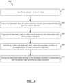
- FIG. 4 shows a block diagram of a method 500 of triggering a feed-back collection event from observation of a manufacturing line 100, the manufacturing line 100 including at least one robotic element 205 for moving at least one part.
- a processor separate from the manufacturing line 100 receives sensor data about the at least one robotic element 205, and when the sensor data exceeds a boundary condition, a feed-back collection event is triggered.
- the steps of the method as described herein may be conducted remotely, by a human operator controlling the operations of the above-described system elements, or autonomously, by a processor configured to automatically control the operations thereof.
- a stream of sensor data is identified by the diagnostic processor 210.
- feed-back data is captured at the data collection device 205 that is associated with at least one robotic element 105.
- the feed-back data is tagged to reflect the at least one part associated with the boundary condition.
- the feed-back data may be tagged to reflect the robotic element 105 associated with the boundary condition.
- identification is done within feed-back data to determine when the boundary condition is exceeded by the at least one part in real time.
- identification may be completed to determined when the boundary condition is exceeded by the robotic element 105.
- the feed-back data relating to the boundary condition in association with the sensor data and the boundary condition is stored.
- the feed-back data may be stored at the diagnostic processor 210 or the data collection devices 205.
- the method 500 may be repeated as many times as desired.
Landscapes
- Engineering & Computer Science (AREA)
- General Engineering & Computer Science (AREA)
- Manufacturing & Machinery (AREA)
- Quality & Reliability (AREA)
- Physics & Mathematics (AREA)
- General Physics & Mathematics (AREA)
- Automation & Control Theory (AREA)
- Manipulator (AREA)
Applications Claiming Priority (1)
| Application Number | Priority Date | Filing Date | Title |
|---|---|---|---|
| US202263405028P | 2022-09-09 | 2022-09-09 |
Publications (1)
| Publication Number | Publication Date |
|---|---|
| EP4336291A1 true EP4336291A1 (de) | 2024-03-13 |
Family
ID=88020988
Family Applications (1)
| Application Number | Title | Priority Date | Filing Date |
|---|---|---|---|
| EP23196685.4A Pending EP4336291A1 (de) | 2022-09-09 | 2023-09-11 | Systeme und verfahren zur diagnose von herstellungssystemen |
Country Status (2)
| Country | Link |
|---|---|
| US (1) | US20240184273A1 (de) |
| EP (1) | EP4336291A1 (de) |
Citations (4)
| Publication number | Priority date | Publication date | Assignee | Title |
|---|---|---|---|---|
| US20190302751A1 (en) * | 2016-07-07 | 2019-10-03 | Ats Automation Tooling Systems Inc. | System and method for diagnosing automation systems |
| US20210097442A1 (en) * | 2018-06-13 | 2021-04-01 | Ats Automation Tooling Systems Inc. | System and method for triggering a training event |
| EP3835902A1 (de) * | 2018-08-06 | 2021-06-16 | OMRON Corporation | Steuerungssystem und steuerungsvorrichtung |
| US20220066435A1 (en) * | 2020-11-10 | 2022-03-03 | Intel Corporation | Real-time anomaly detection for industrial processes |
-
2023
- 2023-09-11 EP EP23196685.4A patent/EP4336291A1/de active Pending
- 2023-09-11 US US18/465,079 patent/US20240184273A1/en active Pending
Patent Citations (4)
| Publication number | Priority date | Publication date | Assignee | Title |
|---|---|---|---|---|
| US20190302751A1 (en) * | 2016-07-07 | 2019-10-03 | Ats Automation Tooling Systems Inc. | System and method for diagnosing automation systems |
| US20210097442A1 (en) * | 2018-06-13 | 2021-04-01 | Ats Automation Tooling Systems Inc. | System and method for triggering a training event |
| EP3835902A1 (de) * | 2018-08-06 | 2021-06-16 | OMRON Corporation | Steuerungssystem und steuerungsvorrichtung |
| US20220066435A1 (en) * | 2020-11-10 | 2022-03-03 | Intel Corporation | Real-time anomaly detection for industrial processes |
Also Published As
| Publication number | Publication date |
|---|---|
| US20240184273A1 (en) | 2024-06-06 |
Similar Documents
| Publication | Publication Date | Title |
|---|---|---|
| KR101614013B1 (ko) | 쇼벨, 그 감시장치 및 쇼벨의 출력장치 | |
| US7398186B2 (en) | Data acquisition system for system monitoring | |
| CN107614215B (zh) | 故障诊断装置及故障诊断方法 | |
| US20220100186A1 (en) | Control system for machine with a plurality of components and methods of operation | |
| CN109661626B (zh) | 用于诊断自动化系统的系统和方法 | |
| US9042708B2 (en) | Digital video recording and playback of user displays in a process control system | |
| WO2015166349A1 (en) | Trending machine health data using rfid transponders | |
| CA2578621A1 (en) | Diagnostic data gathering apparatus and method | |
| CN114254449A (zh) | 信息处理方法和装置、显示方法和装置、记录介质、产品制造方法、以及学习数据获取方法 | |
| KR20170043164A (ko) | 산업플랜트 정비 지원 단말기 | |
| CN114326719A (zh) | 巡检机器人控制方法、系统、计算机设备及存储介质 | |
| EP4336291A1 (de) | Systeme und verfahren zur diagnose von herstellungssystemen | |
| JP2008217608A (ja) | 産業機械の遠隔監視システム及び方法 | |
| KR101917477B1 (ko) | 권취 설비 이상 사전 감지 장치 | |
| JP3631204B2 (ja) | 故障診断システム、故障診断装置、及びコンピュータプログラム | |
| CN112400194A (zh) | 用于触发训练事件的系统和方法 | |
| JP6875850B2 (ja) | フィールドデータ収集システム | |
| CA2848554C (en) | System and method for storing and monitoring events at security devices | |
| JP2000259455A (ja) | 設備障害管理装置および設備障害管理方法、ならびに記憶媒体 | |
| JP4980687B2 (ja) | 監視システム | |
| JP3124414B2 (ja) | 監視制御装置 | |
| JP7812957B2 (ja) | 監視装置、監視システム、監視方法および監視プログラム | |
| US20250328129A1 (en) | Automation System Comprising an Equipment Inspecting Carriage | |
| TW201301807A (zh) | 障礙資訊處理裝置、障礙資訊處理方法,以及障礙資訊處理系統 | |
| JP2004272431A (ja) | 電力系統計算機オンライン保守システム |
Legal Events
| Date | Code | Title | Description |
|---|---|---|---|
| PUAI | Public reference made under article 153(3) epc to a published international application that has entered the european phase |
Free format text: ORIGINAL CODE: 0009012 |
|
| STAA | Information on the status of an ep patent application or granted ep patent |
Free format text: STATUS: THE APPLICATION HAS BEEN PUBLISHED |
|
| AK | Designated contracting states |
Kind code of ref document: A1 Designated state(s): AL AT BE BG CH CY CZ DE DK EE ES FI FR GB GR HR HU IE IS IT LI LT LU LV MC ME MK MT NL NO PL PT RO RS SE SI SK SM TR |
|
| RAP1 | Party data changed (applicant data changed or rights of an application transferred) |
Owner name: ATS CORPORATION |
|
| RIN1 | Information on inventor provided before grant (corrected) |
Inventor name: BORONKA, KEVIN Inventor name: HOWARTH, CODY Inventor name: SULLIVAN, GREGORY Inventor name: CARTER, AMY |
|
| STAA | Information on the status of an ep patent application or granted ep patent |
Free format text: STATUS: REQUEST FOR EXAMINATION WAS MADE |
|
| 17P | Request for examination filed |
Effective date: 20240913 |
|
| RBV | Designated contracting states (corrected) |
Designated state(s): AL AT BE BG CH CY CZ DE DK EE ES FI FR GB GR HR HU IE IS IT LI LT LU LV MC ME MK MT NL NO PL PT RO RS SE SI SK SM TR |