EP4336041A2 - Taumelscheibenkolbenwasserpumpe zur verwendung in einer niederstrom-gasdruckscheibe oder einer niederstrom-elektrodruckscheibe - Google Patents
Taumelscheibenkolbenwasserpumpe zur verwendung in einer niederstrom-gasdruckscheibe oder einer niederstrom-elektrodruckscheibe Download PDFInfo
- Publication number
- EP4336041A2 EP4336041A2 EP24153676.2A EP24153676A EP4336041A2 EP 4336041 A2 EP4336041 A2 EP 4336041A2 EP 24153676 A EP24153676 A EP 24153676A EP 4336041 A2 EP4336041 A2 EP 4336041A2
- Authority
- EP
- European Patent Office
- Prior art keywords
- wobble plate
- piston
- water
- pistons
- pump
- Prior art date
- Legal status (The legal status is an assumption and is not a legal conclusion. Google has not performed a legal analysis and makes no representation as to the accuracy of the status listed.)
- Granted
Links
Images


Classifications
-
- F—MECHANICAL ENGINEERING; LIGHTING; HEATING; WEAPONS; BLASTING
- F04—POSITIVE - DISPLACEMENT MACHINES FOR LIQUIDS; PUMPS FOR LIQUIDS OR ELASTIC FLUIDS
- F04B—POSITIVE-DISPLACEMENT MACHINES FOR LIQUIDS; PUMPS
- F04B1/00—Multi-cylinder machines or pumps characterised by number or arrangement of cylinders
- F04B1/12—Multi-cylinder machines or pumps characterised by number or arrangement of cylinders having cylinder axes coaxial with, or parallel or inclined to, main shaft axis
- F04B1/14—Multi-cylinder machines or pumps characterised by number or arrangement of cylinders having cylinder axes coaxial with, or parallel or inclined to, main shaft axis having stationary cylinders
- F04B1/18—Multi-cylinder machines or pumps characterised by number or arrangement of cylinders having cylinder axes coaxial with, or parallel or inclined to, main shaft axis having stationary cylinders having self-acting distribution members, i.e. actuated by working fluid
- F04B1/182—Check valves
-
- F—MECHANICAL ENGINEERING; LIGHTING; HEATING; WEAPONS; BLASTING
- F04—POSITIVE - DISPLACEMENT MACHINES FOR LIQUIDS; PUMPS FOR LIQUIDS OR ELASTIC FLUIDS
- F04B—POSITIVE-DISPLACEMENT MACHINES FOR LIQUIDS; PUMPS
- F04B1/00—Multi-cylinder machines or pumps characterised by number or arrangement of cylinders
- F04B1/12—Multi-cylinder machines or pumps characterised by number or arrangement of cylinders having cylinder axes coaxial with, or parallel or inclined to, main shaft axis
- F04B1/14—Multi-cylinder machines or pumps characterised by number or arrangement of cylinders having cylinder axes coaxial with, or parallel or inclined to, main shaft axis having stationary cylinders
- F04B1/141—Details or component parts
- F04B1/146—Swash plates; Actuating elements
- F04B1/148—Bearings therefor
-
- F—MECHANICAL ENGINEERING; LIGHTING; HEATING; WEAPONS; BLASTING
- F04—POSITIVE - DISPLACEMENT MACHINES FOR LIQUIDS; PUMPS FOR LIQUIDS OR ELASTIC FLUIDS
- F04B—POSITIVE-DISPLACEMENT MACHINES FOR LIQUIDS; PUMPS
- F04B1/00—Multi-cylinder machines or pumps characterised by number or arrangement of cylinders
- F04B1/12—Multi-cylinder machines or pumps characterised by number or arrangement of cylinders having cylinder axes coaxial with, or parallel or inclined to, main shaft axis
- F04B1/26—Control
- F04B1/28—Control of machines or pumps with stationary cylinders
-
- F—MECHANICAL ENGINEERING; LIGHTING; HEATING; WEAPONS; BLASTING
- F04—POSITIVE - DISPLACEMENT MACHINES FOR LIQUIDS; PUMPS FOR LIQUIDS OR ELASTIC FLUIDS
- F04B—POSITIVE-DISPLACEMENT MACHINES FOR LIQUIDS; PUMPS
- F04B17/00—Pumps characterised by combination with, or adaptation to, specific driving engines or motors
- F04B17/03—Pumps characterised by combination with, or adaptation to, specific driving engines or motors driven by electric motors
-
- F—MECHANICAL ENGINEERING; LIGHTING; HEATING; WEAPONS; BLASTING
- F04—POSITIVE - DISPLACEMENT MACHINES FOR LIQUIDS; PUMPS FOR LIQUIDS OR ELASTIC FLUIDS
- F04B—POSITIVE-DISPLACEMENT MACHINES FOR LIQUIDS; PUMPS
- F04B17/00—Pumps characterised by combination with, or adaptation to, specific driving engines or motors
- F04B17/05—Pumps characterised by combination with, or adaptation to, specific driving engines or motors driven by internal-combustion engines
-
- F—MECHANICAL ENGINEERING; LIGHTING; HEATING; WEAPONS; BLASTING
- F04—POSITIVE - DISPLACEMENT MACHINES FOR LIQUIDS; PUMPS FOR LIQUIDS OR ELASTIC FLUIDS
- F04B—POSITIVE-DISPLACEMENT MACHINES FOR LIQUIDS; PUMPS
- F04B43/00—Machines, pumps, or pumping installations having flexible working members
-
- F—MECHANICAL ENGINEERING; LIGHTING; HEATING; WEAPONS; BLASTING
- F04—POSITIVE - DISPLACEMENT MACHINES FOR LIQUIDS; PUMPS FOR LIQUIDS OR ELASTIC FLUIDS
- F04B—POSITIVE-DISPLACEMENT MACHINES FOR LIQUIDS; PUMPS
- F04B43/00—Machines, pumps, or pumping installations having flexible working members
- F04B43/02—Machines, pumps, or pumping installations having flexible working members having plate-like flexible members, e.g. diaphragms
-
- F—MECHANICAL ENGINEERING; LIGHTING; HEATING; WEAPONS; BLASTING
- F04—POSITIVE - DISPLACEMENT MACHINES FOR LIQUIDS; PUMPS FOR LIQUIDS OR ELASTIC FLUIDS
- F04B—POSITIVE-DISPLACEMENT MACHINES FOR LIQUIDS; PUMPS
- F04B49/00—Control, e.g. of pump delivery, or pump pressure of, or safety measures for, machines, pumps, or pumping installations, not otherwise provided for, or of interest apart from, groups F04B1/00 - F04B47/00
- F04B49/02—Stopping, starting, unloading or idling control
- F04B49/022—Stopping, starting, unloading or idling control by means of pressure
-
- F—MECHANICAL ENGINEERING; LIGHTING; HEATING; WEAPONS; BLASTING
- F04—POSITIVE - DISPLACEMENT MACHINES FOR LIQUIDS; PUMPS FOR LIQUIDS OR ELASTIC FLUIDS
- F04B—POSITIVE-DISPLACEMENT MACHINES FOR LIQUIDS; PUMPS
- F04B2203/00—Motor parameters
- F04B2203/02—Motor parameters of rotating electric motors
- F04B2203/0201—Current
-
- F—MECHANICAL ENGINEERING; LIGHTING; HEATING; WEAPONS; BLASTING
- F04—POSITIVE - DISPLACEMENT MACHINES FOR LIQUIDS; PUMPS FOR LIQUIDS OR ELASTIC FLUIDS
- F04B—POSITIVE-DISPLACEMENT MACHINES FOR LIQUIDS; PUMPS
- F04B2203/00—Motor parameters
- F04B2203/02—Motor parameters of rotating electric motors
- F04B2203/0202—Voltage
-
- F—MECHANICAL ENGINEERING; LIGHTING; HEATING; WEAPONS; BLASTING
- F04—POSITIVE - DISPLACEMENT MACHINES FOR LIQUIDS; PUMPS FOR LIQUIDS OR ELASTIC FLUIDS
- F04B—POSITIVE-DISPLACEMENT MACHINES FOR LIQUIDS; PUMPS
- F04B2203/00—Motor parameters
- F04B2203/06—Motor parameters of internal combustion engines
- F04B2203/0604—Power
Definitions
- the following relates generally to a water pump and more specifically to a wobble plate piston water pump for use in a low flow gas pressure washer or a low current electric pressure washer.
- a multitude of household and light commercial pressure washers are on the market. These washers, for the purposes of the following, are those that provide pressurized water at under 3500 pounds-per-square-inch (psi) with a water flow rate of less than 3.0 gallons per minute (gpm).
- Efforts to increase the power of a pressure washer would generally include altering certain elements of the water pump, such as increasing motor strength or replacing the brushed motor with a brushless motor.
- altering certain elements of the water pump such as increasing motor strength or replacing the brushed motor with a brushless motor.
- these conventional alterations generally result in impairments that make the pressure washer impractical, overly expensive, and/or non-functional.
- a wobble plate piston water pump for use in a pressure washer and driven by a driving source, the driving source being electric powered and having a power consumption of less than or equal to a 15 ampere draw at 120 volts or 220 volts or the driving source being gas powered and having an engine displacement of less than or equal to 250 cubic centimetres
- the water pump includes: a pump body defining a plurality of channels; a wobble plate disposed in the pump body and having a rear side and a front side, the wobble plate being rotatable around a rotational axis via mechanical connection on the rear side to the driving source, the front side being inclined at an angle relative to the rotational axis; four or more pistons each having a proximate end and a distal end, each piston located in a respective one of the plurality of channels and each having a thrust ball bearing located on the proximate end, the thrust ball bearing of each piston being biased to contact the front side of the wobble plate, the pistons being reciproc
- the four or more pistons consist of five pistons.
- the four or more pistons consist of six pistons.
- the wobble plate piston water pump further includes a power-off subassembly located intermediate the water outlet and a closeable water nozzle, the power-off subassembly defining a push rod cavity for receiving water from the water outlet, the power off subassembly includes: a push rod at least partially located in the push rod cavity, the push rod moveably biased towards being in the push rod cavity; and a microswitch electrical connected to a power supply of the driving source, the microswitch positioned such that push rod contacts the microswitch when the push rod cavity is substantially filled with water due to a closed water nozzle, and contact with the microswitch by the push rod turns off power to the driving source.
- the driving source is an electric motor and the diameter of each of the pistons is between 8mm and 14mm.
- the driving source is a gas engine and the diameter of each of the pistons is between 10mm and 16mm.
- the driving source is an electric motor and the angle of the front side of the wobble plate is between 5 degrees and 8 degrees.
- the driving source is a gas engine and the angle of the front side of the wobble plate is between 6 degrees and 10 degrees.
- the wobble plate piston water pump further includes a transmission subassembly located intermediate the driving source and the wobble plate, the transmission subassembly configured to rotate the wobble plate between four to six times the rate of reciprocating each of the pistons.
- a method for pumping out high-pressure water from a low pressure water source using a wobble plate piston water pump driven by a driving source the driving source being electric powered and having a power consumption of less than or equal to a 15 ampere draw at 120 volts or 220 volts or the driving source being gas powered and having an engine displacement of less than or equal to 250 cubic centimetres
- the method includes: rotating a wobble plate around a rotational axis via mechanical connection to the driving source, a front side of the wobble plate being inclined at an angle relative to the rotational axis; biasing four or more pistons towards the front side of the wobble plate with a thrust ball bearing disposed intermediate each of the pistons and the wobble plate; reciprocating the four or more pistons in separate channels along an axis transverse to the rotational axis during rotation of the wobble plate, the channels defined by a pump body; receiving low pressure water from a water inlet to at least one of the channels when the piston for that respective channel is moving
- the biasing of the four or more pistons consists of biasing exactly five pistons and the reciprocating of the four or more pistons consists of reciprocating exactly five pistons.
- expelling the high-pressure water includes expelling the high-pressure water to a closeable water nozzle, and wherein the method further includes ceasing reciprocation of the pistons if the closeable water nozzle is closed.
- Applicant has recognized that for conventional three piston water pumps, altering a single element of the pump will not necessarily increase performance for a water pump, and in some circumstances, may even reduce performance. Through repeated testing and study, Applicant recognized the following set of mechanical propositions for piston-type water pumps when a single element of the pump was altered:
- Applicant has determined that comprehensively improving the performance of a three piston water pump by merely altering elements or making local improvements is generally impractical. Such impracticality is likely why product performance of such pumps has not materially gained any significant progress for possibly decades.
- the above impairments are especially concerning for low flow gas pressure washers or low current electric water pressure washers.
- the driving source is electric powered and has a power consumption of less than or equal to a 15 ampere draw at 120 volts or 220 volts; or where the driving source is gas powered and has an engine displacement of less than or equal to 250 cubic centimetres.
- FIG. 1 an exemplary embodiment of a wobble plate piston water pump is shown in cross-sectional side view.
- the motor is shown as an induction motor and the pump is a wobble plate pump.
- the wobble plate piston water pump includes a high-pressure generation subassembly, a pressure retaining subassembly, a mechanical-electronic pressure safety control subassembly and a cleaning solution auto-generation subassembly.
- the wobble plate piston water pump may not be delineated into subassemblies, or may be delineated into more or less subassemblies, each having or sharing different configurations of the disclosed components.
- the wobble plate piston water pump includes a pump body which is made up of a front pump body 14, an intermediate pump body 13, and a rear pump body 12.
- the wobble plate piston water pump includes four or more pistons 10 (also called plungers) each located in the high-pressure generation subassembly.
- the high-pressure generation subassembly is composed of a wobble plate 7 (also called a tilting tray), thrust ball bearings 8, a plurality of pistons 10 and piston springs 11.
- the wobble plate 7 has a front side and a rear side.
- the rear side of the wobble plate 7 is in mechanical connection with a driving source 5.
- the mechanical connection can be via affixation to a front end of a rotating spindle 1 (also called a shaft) of the driving source 5.
- the wobble plate 7 is mounted at an angle offset from the vertical, relative to the spindle, by a particular offset.
- the wobble plate 7 is affixed to a lateral end of the spindle 1 through a bolt 2, a shaft key 3 and a washer 4.
- any structure for affixing the wobble plate 7 to the spindle 1 may be used.
- Each of the plurality of pistons 10 have a proximate end and a lateral end.
- the thrust ball bearings 8 are located at the proximate end of each of the pistons 10.
- the plurality of pistons 10 are disposed adjacent and in contact, via the thrust ball bearings 8, with the wobble plate 7.
- the contact is maintained by a spring 11 disposed between a spring retainer 9 part of the piston 10 adjacent the wobble plate 7 and a distal wall of a channel P6.
- the spring 11 is biased to urge the piston 10 toward the wobble plate 7.
- the wobble plate 7 rotates with the shaft 1, which causes each piston to reciprocate in the channel P6 along an axis transverse to the rotation of the wobble plate 7, due to following along with the angled front side of the wobble plate 7.
- the plurality of pistons 10 are positioned to be concentrically and uniformly distributed around the wobble plate 7.
- the thrust ball bearings 8 provided on the wobble plate 7 are biased towards a movable ring of the thrust ball bearings 8 under the action of the piston springs 11.
- the pistons 10 are approximately concentrically distributed in an annular direction, the horizontal positions of the pistons 10 are also uniformly annularly distributed over the front side of the wobble plate 7; such that each of the pistons are at different distances from the distal end of the corresponding channel at any one time.
- the Applicant has determined that it is advantageous for the pitch diameter to be between 35mm to 60mm for an electric-powered pump and between 40mm to 80mm for a gas-powered pump.
- the high-pressure generation subassembly also includes a transmission box body 6, a piston elastic retainer ring 9, an oil-proof sealing ring 41, a high-pressure water outlet joint 15, the front pump body 14, a first O-shaped ring 16 and a non-reflux check valve 17.
- the transmission box body 6 is connected, typically with a front end cover, to the motor 5 (or an engine).
- the piston elastic retainer ring 9 is positioned at the rear end of the piston 10.
- the oil-proof sealing ring 41 is mounted on a rear of the pump and is concentric with the piston 10.
- the high-pressure water outlet joint 15 is connected with a front pump body 14 through threads.
- the non-reflux check valve 17 is mounted at the inner side of the high-pressure water outlet joint 15.
- the pressure retaining subassembly includes the rear pump body 12, the intermediate pump body 13, water inlet check valves 35, water outlet check valves 37, check valve inner sleeves 38, a waterproof sealing ring 39, a sealing ring fixing ring 40, a check valve support frame 36, a low-pressure water inlet joint 26 and a fifth O-shaped ring 26.
- the water inlet check valves 35 are mounted in small cavities that are uniformly distributed in a annular direction between the intermediate pump body 13 and the rear pump body 12.
- the water inlet check valve 35 generally provides a high flow and low pressure water source.
- Each inlet check valve 35 is in fluid communication with at least one of the pistons 10, a low pressure chamber P2, and a low-pressure cavity water outlet P3.
- the water outlet check valve 37 generally constraints the flow of fluid, for example using a smaller diameter conduit than the fluid inlet.
- the water outlet check valves 37 and the check valve inner sleeves 38 are mounted in independent small cavities of the rear pump body 12 and are uniformly distributed in a annular direction.
- a water inlet P7 of each of the water outlet check valves 37 is in fluid communication with a water outlet P6 of the corresponding water inlet check valve 35 through an adjacent small side hole P8.
- a water outlet P5, having water outlet entrance P4, of each of the water outlet check valves 37 is
- the waterproof sealing ring 39 and the sealing ring fixing ring 40 are mounted on the rear pump body 12 and are concentric with the piston 10.
- the low-pressure water inlet joint 26 is directly connected with the front pump body 14.
- the mechanical-electronic pressure safety control subassembly consists of an overflow valve core 19, a second O-shaped ring 18, a third O-shaped ring 20, an overflow valve main spring 21, a pressure ring 22, a fourth O-shaped ring 23, a valve rod support ring 24, the fifth O-shaped ring 26, a power-off push rod spring 27, a microswitch box 29, a microswitch 30, a power-off push rod 31, a push rod support ring 32, a push rod locking nut 33 and a push rod waterproof sealing ring 34.
- the microswitch 30 is mounted in the microswitch box 29.
- An internal wire (not shown) connected with the microswitch 30 is connected with a motor outgoing line (not shown).
- the microswitch box 29 is fixed to the front pump body 14 through a U-shaped pin 28, the power-off push rod 31, the power-off push rod spring 27, the push rod support ring 32, the push rod locking nut 33 and the push rod waterproof sealing ring 34, which are mounted in a push rod cavity of the front pump body 14.
- the power-off push rod 31 is concentric with a small hole in the microswitch box 29 and is aligned to a microswitch key (not shown).
- the overflow valve core 19, the overflow valve main spring 21, the pressure ring 22 and the valve rod support ring 24 are mounted in an overflow valve cavity that is concentric with the push rod cavity, and the two cavities are in mechanical communication through a small hole.
- the cleaning solution auto-generation subassembly includes a Venturi valve (not shown) and a cleaning solution check valve (not shown).
- the pistons for an electric motor can have for example a size of between 8mm and 14mm and the pistons for a gasoline engine can have for example a size of between 10mm and 16mm.
- the motor 5 can be any driving source known in the art; for example, a gasoline engine or an electric motor.
- Electric motors for the purposes of this disclosure can be generally divided into two categories, induction motors and series-wound motors. Each category can be further divided into a low-voltage type motors (100V to 120V) and a high-voltage (and high-pressure) type motors (200V to 240V) according to different power supplies.
- the driving source can be electric powered and have a power consumption of less than or equal to a 15 ampere draw at 120 volts or 220 volts.
- the driving source can be gas powered and have an engine displacement of less than or equal to 250 cubic centimetres
- the motor 5 is connected to a direct drive transmission; however, any suitable transmission subassembly may be used.
- a direct drive transmission the motor 5 is connected to the water pump through the wobble plate 7, whereby the wobble plate 7 is directly fixed to the spindle 1, and the rotating speed of the motor 5 is the same as the moving speed of the piston 10.
- the wobble plate 7 is not directly connected with the motor rotor spindle 1, but the spindle 1 of the motor 5 is connected with the wobble plate 7 through a group or multiple stages of reduction gears (not shown), and the rotating speed of the motor 5 can be, for example, four to six times of the reciprocating speed of the pistons 10.
- the wobble plate 7 makes a rotational movement along an axis of the motor.
- the plurality of pistons 10 periodically reciprocate, in the channel P6, on an axis transverse to the rotation of the wobble plate 7 due to the bias of the springs 11 forcing the pistons 10 towards the wobble plate 7. In this way, the pistons 10 are forced to make a horizontal reciprocating movement simultaneous to the rotation of the wobble plate 7.
- the movement positions each of the pistons 10 at uniformly distributed horizontal positions throughout the rotational cycle. For example, at a certain point in time in a five piston water pump, when the first piston reaches the distal end, the adjacent second piston will be moving towards the distal end and compressed 4/5 of the distance towards the distal end.
- the third piston (adjacent to the second piston) will be moving towards the distal end and located at 2/5 of the distance towards the distal end.
- the fourth piston (adjacent to the third piston) will be moving towards the proximate end and will be located at 1/5 of the distance towards the distal end.
- the fifth piston (adjacent to the third piston) will be moving towards the proximate end and will be located at 3/5 of the distance towards the distal end.
- the portion of the channel P6 in front of the piston 10 forms a local vacuum in conjunction with the waterproof sealing ring 39, the water inlet check valve 35 and the water outlet check valve 37.
- the portion of the channel P6 in front of the piston is gradually expanded, and a vacuum of negative pressure formed therein also builds gradually.
- the water inlet check valve 35 is opened and the water outlet check valve 37 remains closed.
- An external water source flows into the portion of the channel P6 in front of the piston from a water inlet hole P1 of a low-pressure water inlet joint 25 under the action of negative pressure. The piston 10 then moves forward toward the distal end, and the water inlet check valve 35 is closed.
- the portion of the channel P6 in front of the piston is gradually decreased in size and the water inside the cavity becomes pressurized.
- the water outlet check valve 37 is opened and high-pressure water flows through the water outlet check valve 37 and into a sub-pressure cavity P9.
- This reciprocating movement of the piston 10, with the corresponding water intake and outtake, is repeated circularly and cyclically, in turn, amongst the five pistons.
- the external low-pressure water source is transformed into a high-pressure water flow, which is then conveyed to the sub-high pressure cavity P9.
- bypass valve P11 having a bypass valve entrance P10, that is in fluid communication with a pressurized water discharge port P12.
- the high-pressure water outlet joint 15 forming part of the pressurized water discharge port P12.
- the wobble plate piston water pump may be connected to a closeable water nozzle (not shown) (also called a water gun). If the water nozzle is closed, the water pressure inside the sub-high pressure cavity P9 continues to raise as high pressure water is delivered. When the pressure in the sub-high pressure cavity P9 exceeds the elastic force of the overflow valve main spring 21 and the power-off push rod spring 27, the overflow valve core 19 pushes the power-off push rod 31 to move outwards. The power-off push rod 31 moves until it comes into contact with a microswitch 30. Upon contact with the microswitch 30, the microswitch 30 powers off a power supply which stops operation of both the motor 5. At this point, the wobble plate piston water pump is in a standby state. When the water nozzle is opened, the microswitch 30 is opened, the motor begins operating again, and a high pressure water flow is pumped out through the water nozzle.
- a closeable water nozzle also called a water gun
- the water nozzle may be able to be set to a low-pressure mode.
- the water flow will generate local vacuum in front of the Venturi valve (not shown) mounted in the high-pressure water outlet joint 15.
- the cleaning solution check valve (not shown) is opened.
- the cleaning solution check valve is mounted in front of the Venturi valve. A cleaning solution is drawn into the high-pressure water outlet joint 15 from a cleaning solution receptacle and flows out of the water nozzle together with the low-pressure water flow.
- FIG. 3 An exemplary embodiment of a pump body 50 is shown in FIG. 3 .
- the pump body 50 includes five channels 52 and correspondingly includes five pistons 54 located in the channels 52. As shown, the five pistons 54 are annular spaced around the central axis of the wobble plate (not shown).
- FIG. 3 illustrates a five piston arrangement
- the number of pistons could be four, five, six, seven or even more.
- the number of pistons based on the diameter of the wobble plate, the pump piston diameter, the pitch circle diameter and the piston diameters. It is necessary to provide some separation between the channels so that fluid is not communicated between channels (i.e., leakage).
- leakage any of these components can be custom designed, for cost reasons (purchasing certain components off the shelf) there is generally a common range of acceptable diameters.
- the Applicant took into consideration various constraints, such as the constraints on the pistons; for example, the amperage draw, torque limitation, manufacturing cost, and the like. Further, the Applicant also took into consideration the constraints on the wobble plate, for example, the amperage draw, torque limitation, and the like.
- the Applicant has determined that the pistons can have a diameter of between 8mm to 14mm for an electric pressure washer and between 10mm to 16mm for a gas pressure washer.
- the Applicant has also determined that advantageously the pitch circle of the wobble plate be between 35mm to 60mm for an electric pressure washer and between 40mm to 80mm for a gas pressure washer.
- the Applicant also determined that the pitch circle in these circumstances generally has to be above 35mm, and preferably above 40mm, due to structural constraints.
- a suitable wobble plate angle for a five pistons arrangement may be between 5 degrees and 8 degrees for an electric pressure washer and between 6 degrees and 10 degrees for a gas pressure washer.
- the Applicant also determined that the pitch circle in these circumstances generally has to be above 5 degrees or else the torque generated will be too low and not sufficiently efficient.
- FIG. 4 shows a schematic view of an exemplary embodiment of a five piston wobble plate piston pump for water pressure washers.
- a motor 128 is connected to and rotationally drives the wobble plate 126.
- the wobble plate 126 is in mechanical communication with the five pistons 124 to produce horizontal reciprocating motion of the pistons 124.
- the pistons 124 are shown in a linear configuration. In practice, the pistons 124 are annularly spaced around the front side of the wobble plate 126.
- Each of the channels 125 is in selective fluid communication with a water passage based on the phase of reciprocation of the respective piston 124 in that channel 125.
- the water passage defined by a water inlet and water outlet.
- the water inlet check valve 122 provides water to each channel 125 when the respective piston 124 in that channel 125 is moving away from that water inlet.
- a low-pressure water source 118 feeds water to a low-pressure cavity 120, which then feeds water to the water inlet check valves 122.
- Each of the pistons 124 is in fluid communication with a water outlet check valve 116 as part of the exit path for the pressurized water.
- the water outlet receives water from each channel 125 when the respective piston 124 in that channel 125 is moving towards that water outlet.
- Each of the water outlet check valves 116 feed into a main check valve 114.
- the high-pressurized water flows along an outlet path 106 past a Venturi jet valve 104 to a water nozzle 100.
- a pressure valve 102 connected to a cleaning solution source to feed cleaning solution into the output water via fluid dynamics created by the Venturi jet valve 104.
- Microswitch electrical leads 110 and 112, of a microswitch 113 are electrically connected to the power supply of the motor 128 such that the microswitch 113 can turn off the motor 128 in certain circumstances.
- a power-off subassembly 108 is in fluid communication with the high-pressure outlet path 106.
- the power-off subassembly defines a push rod cavity 109.
- a push rod 111 is at least partially located in the push rod cavity 109, the push rod 111 is moveably biased towards being in the push rod cavity by, for example, a push rod spring.
- a push rod 111 moves out of the push rod cavity 109 and into contact with the microswitch 113.
- the microswitch 113 then turns off the power to the motor 128.
- the microswitch 113 returns power to the motor 128 when the push rod cavity begins to empty its water and the pressurized water can once again move along the path towards the water nozzle 100.
- the wobble plate water pump as described herein, can be used for a method for pumping out high-pressure water from a low pressure water source.
- the method includes reciprocating four or more pistons in separate channels. Then, receiving water from the low pressure water source into a distal end of at least one of the channels when the corresponding piston is moving away from the distal end. Then, pressurizing the water by moving the corresponding piston towards the distal end of the at least one channel. Then, expelling the high-pressure water from the at least one channel prior to the corresponding piston moving away from the distal end.
- the receiving water to expelling water steps are sequentially repeated for each of the channels.
- Each of the pistons being at different distances from the distal end of the corresponding channel at any one time.
- the method is for exactly five reciprocating pistons.
- the high-pressure water is expelled to a closeable water nozzle. Where reciprocation of the pistons is ceased if the closeable water nozzle is closed.
- cleaning solution is added to the expelled water.
- Applicant recognized numerous advantages of the embodiments described herein, and particularly, for a five piston arrangement over that of a conventional three piston pump arrangement. For example, Applicant recognized that a five piston arrangement will generally provide a more stable fluid output than the three piston arrangement. This is because there is a shorter delay between consecutive water bursts, as the pistons sequentially provide fluid output. There is also the intended advantage of being able to increase both water pressure and water flow at the same time.
- a smaller diameter piston can be employed. This is because the total channel volume required can be divided by 5 rather than 3. In this case, the power required to drive the wobble plate in view of the counter-force of the water in the channels is decreased.
- the motor can operate at a lower current (for electric motors) or with lower fuel consumption (for a gas motor) in the five piston arrangement as compared to the three piston arrangement, provided a common fluid output is desired.
- This may be important, because there is generally a constraint on the maximum current available to the motor in electric usage (for example, 15 Amperes in a 120 volt or 200 volt electrical system) and there is an immediate cost implication in gas usage (i.e., by reducing consumption).
- this also permits the same motor to be used to drive a higher fluid flow and/or higher pressure in the five piston arrangement as compared to the three piston arrangement, in case there is a desire to drive the motor at maximum capacity.
- the wobble plate piston water pump can tend to become quieter and have a longer life span.
- Applicant measured the performance increase of the five piston water pump over the three piston water pump to be approximately 20% to 25% in particular exemplary cases.
- Applicant has also recognized advantages of the embodiments with a four piston arrangement over the conventional three piston arrangement. Relative to the three piston water pump, Applicant measured the performance of the four piston water pump to be increased by approximately 7% while the size is only increased by approximately 15%. Additionally, the difficulty of machining the pump can be decreased.
- Applicant has also recognized advantages of the embodiments with a six piston arrangement over the conventional three piston arrangement. Relative to the three piston water pump, Applicant measured the performance of the six piston water pump to be increased by approximately 25%.
- the measured performance of the five piston water pump is only a small decrease of approximately 7%.
- the rigidity of a pump body of the six piston water pump is weaker than the five piston pump, the compressive strength of the six piston water pump needs to be maintained by increasing the size and the wall thickness of the whole pump body. This increase can result in increased cost and weight.
- the five piston arrangement can have ideal even distribution among the pitch circle.
- even-numbered piston arrangements such as a four piston arrangement or a six piston arrangement
- a five piston arrangement can have greater long term strength. Since even-numbered piston arrangements belong to an even-number vibrating body, it is possible that those arrangements can be accidentally damaged due to resonance of the pump body during operation.
- IP 0.24 * GPM * 3.785 *SQRT PSI*0 .07 / 0.98 whereby GPM is gallons per minute and PSI is pounds per square inch.
- the curve of cleaning impact force is an inverse parabola as shown in the example of FIG. 5 .
- the following is a technical analysis on a conventional three piston water pump having a diameter of the pistons of 12mm, a diameter of a pitch circle of the pistons of 42mm, and the wobble plate having an angle of 8 degrees.
- the induction motor that drives the pump has a rated voltage (V) of 120V/60Hz, with a motor speed of 3600rpm, and a maximum working current (I) of 15A.
- V rated voltage
- I maximum working current
- HP V * I * Eff 746
- the motor efficiency Eff is 60%.
- the maximum output power of the motor is 1.4 HP.
- FIG. 6 illustrates a side cut-away view of an exemplary pump showing, generally, the screw thrust (Fa), horizontal axial force (Fx) and vertical axial force (Fy) on a piston.
- FIG. 7 shows the relationship between positive efficiency (represented on the vertical axis) and lead angle (represented on the horizontal axis in degrees).
- the hydraulic pressure generated by the water pump is used to estimate the thrust required by the piston. Also it is used to estimate whether it can match with the maximum thrust of the motor. Namely, the axial thrust generated by the motor should be greater than the reaction force generated by high water pressure to the pump.
- the maximum working pressure is 1300PSI (90kg/cm 2 ) when the flow is 1.39 GPM.
- the working current cannot exceed the maximum limit of 15A.
- Fp is the reaction force generated by the water pressure to each piston:
- the horizontal thrust force, Fx (262.2kg), generated by the motor is less than reaction force of the pump, Fb (261kg).
- the water pump has a piston diameter of 13mm, a diameter for the pitch circle of the pistons of 44mm, and an angle for the wobble plate of 7 degrees.
- the primary purpose of reducing the angle of the wobble plate was to enhance the working efficiency of the pump by increasing the thrust of piston in the horizontal direction and decrease the pressure on the piston in the vertical direction. Thus, increase the cleaning impact force.
- the pump uses an induction motor as the driving force.
- the induction motor has a rated voltage (V) of 120V/60Hz, a motor speed of 3600rpm, and a maximum working current (I) of 15A.
- V rated voltage
- I maximum working current
- HP V * I * Eff / 746
- the motor efficiency Eff is 60%.
- the maximum output power of the motor is 1.4 HP.
- the drag coefficient (L) of the wobble plate, thrust ball bearing and piston is 0.025.
- the positive efficiency of slope of 7 degrees ⁇ 1 is 82%.
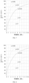
- FIG. 8 shows the relationship between positive efficiency (represented on the vertical axis) and lead angle (represented on the horizontal axis in degrees).
- the hydraulic pressure generated by the high-pressure water pump is used to estimate the thrust required by the piston, and whether it can match with the maximum thrust of the motor.
- the axial thrust generated by the motor should be greater than the reaction force generated by high water pressure to the pump.
- the maximum working pressure is 1300PSI (90kg/cm 2 ) when the flow is 1.43 GPM. At that time, the working current cannot exceed the maximum limit of 15A.
- the horizontal thrust force, Fx (274.9kg), generated by the motor is less than the reaction force of the pump, Fb (296.5kg).
- Fx 274.9kg
- Fb reaction force of the pump
- the five piston water pump has a diameter of the pistons of 10mm, a diameter of a pitch circle of the pistons of 48mm, and an angle of an inclined plate of 6.5 degrees.
- the primary purpose of reducing the angle of the wobble plate is to enhance working efficiency of the pump by increasing the thrust of piston in the horizontal direction, while decreasing the pressure on the piston in the vertical direction. Thus increasing the cleaning impact force.
- the pump is driven by an induction motor.
- the induction motor has a rated voltage (V) of 120V/60Hz, a motor speed of 3600rpm, and a maximum working current (I) of 15A.
- the drag coefficient (L) of the wobble plate, thrust ball bearing and piston is 0.025.
- the positive efficiency of the slope of 6.5 degrees ⁇ 1 is 80%.
- FIG. 9 shows the relationship between positive efficiency (represented on the vertical axis) and lead angle (represented on the horizontal axis in degrees).
- the hydraulic pressure generated by the water pump is used to estimate the thrust required by the piston. It is also used to estimate whether the pump can match with the maximum thrust of the motor. Namely, the axial thrust generated by the motor should be greater than the reaction force generated by high water pressure to the pump.
- the pump has a maximum working pressure of 1300PSI (90kg/cm 2 ) when the flow is 1.64 GPM. At that time, the working current cannot exceed the maximum limit of 15A.
- Ff is the resistance generated by the rubber sealing ring on the piston
- Ff Fy * f
- the horizontal thrust, Fx (268.9kg), generated by the motor is close to reaction force of the pump, Fb (272.4kg).
- Fx (268.9kg)
- Fb reaction force of the pump
- the output power of the motor cannot meet the requirements for normal working conditions of the water pump.
- the rated current of the motor can be maintained within a range for safe operation.
- the motor and five piston pump are working at the point of maximum power.
- the operating flow (1.64GPM) and the operating pressure (1300PSI) are at a practically optimal ratio.
- the cleaning impact (IP) also reaches a practically optimal value.
- the cleaning impact force is increased by 18%. Therefore, the five piston pump has clearly enumerated advantages of the conventional three piston arrangement. Particularly, the five piston pump has enhanced the operating flow and cleaning effects, due to, in this case, increasing the number of pistons to five, decreasing the angle of the wobble plate, and decreasing the diameter of the piston.
Landscapes
- Engineering & Computer Science (AREA)
- Mechanical Engineering (AREA)
- General Engineering & Computer Science (AREA)
- Chemical & Material Sciences (AREA)
- Combustion & Propulsion (AREA)
- Reciprocating Pumps (AREA)
- Electrolytic Production Of Non-Metals, Compounds, Apparatuses Therefor (AREA)
Priority Applications (1)
| Application Number | Priority Date | Filing Date | Title |
|---|---|---|---|
| EP25217567.4A EP4675105A1 (de) | 2016-05-06 | 2016-10-05 | Taumelscheibenkolbenwasserpumpe zur verwendung in einer niederstrom-gasdruckscheibe oder einer niederstrom-elektrodruckscheibe |
Applications Claiming Priority (5)
| Application Number | Priority Date | Filing Date | Title |
|---|---|---|---|
| US201662332808P | 2016-05-06 | 2016-05-06 | |
| CN201620606037.3U CN205937011U (zh) | 2016-04-22 | 2016-06-20 | 新型多柱塞组高压水泵及应用水泵的高压系统 |
| CN201610443275.1A CN105927493A (zh) | 2016-04-22 | 2016-06-20 | 新型多柱塞组高压水泵及应用水泵的高压系统及运行方法 |
| EP16900782.0A EP3452723B1 (de) | 2016-05-06 | 2016-10-05 | Taumelscheibenkolbenwasserpumpe zur verwendung in einer niederstrom-gasdruckscheibe oder einer niederstrom-elektrodruckscheibe |
| PCT/CA2016/051158 WO2017190212A1 (en) | 2016-05-06 | 2016-10-05 | Wobble plate piston water pump for use in a low flow gas pressure washer or a low current electric pressure washer |
Related Parent Applications (2)
| Application Number | Title | Priority Date | Filing Date |
|---|---|---|---|
| EP16900782.0A Division EP3452723B1 (de) | 2016-05-06 | 2016-10-05 | Taumelscheibenkolbenwasserpumpe zur verwendung in einer niederstrom-gasdruckscheibe oder einer niederstrom-elektrodruckscheibe |
| EP16900782.0A Division-Into EP3452723B1 (de) | 2016-05-06 | 2016-10-05 | Taumelscheibenkolbenwasserpumpe zur verwendung in einer niederstrom-gasdruckscheibe oder einer niederstrom-elektrodruckscheibe |
Related Child Applications (2)
| Application Number | Title | Priority Date | Filing Date |
|---|---|---|---|
| EP25217567.4A Division EP4675105A1 (de) | 2016-05-06 | 2016-10-05 | Taumelscheibenkolbenwasserpumpe zur verwendung in einer niederstrom-gasdruckscheibe oder einer niederstrom-elektrodruckscheibe |
| EP25217567.4A Division-Into EP4675105A1 (de) | 2016-05-06 | 2016-10-05 | Taumelscheibenkolbenwasserpumpe zur verwendung in einer niederstrom-gasdruckscheibe oder einer niederstrom-elektrodruckscheibe |
Publications (3)
| Publication Number | Publication Date |
|---|---|
| EP4336041A2 true EP4336041A2 (de) | 2024-03-13 |
| EP4336041A3 EP4336041A3 (de) | 2024-05-15 |
| EP4336041B1 EP4336041B1 (de) | 2026-01-28 |
Family
ID=83998609
Family Applications (2)
| Application Number | Title | Priority Date | Filing Date |
|---|---|---|---|
| EP24153676.2A Active EP4336041B1 (de) | 2016-05-06 | 2016-10-05 | Taumelscheibenkolbenwasserpumpe für den einsatz in einem druckreiniger mit geringer gasdurchflussmenge oder in einem druckreiniger mit geringer stromstärke |
| EP25217567.4A Pending EP4675105A1 (de) | 2016-05-06 | 2016-10-05 | Taumelscheibenkolbenwasserpumpe zur verwendung in einer niederstrom-gasdruckscheibe oder einer niederstrom-elektrodruckscheibe |
Family Applications After (1)
| Application Number | Title | Priority Date | Filing Date |
|---|---|---|---|
| EP25217567.4A Pending EP4675105A1 (de) | 2016-05-06 | 2016-10-05 | Taumelscheibenkolbenwasserpumpe zur verwendung in einer niederstrom-gasdruckscheibe oder einer niederstrom-elektrodruckscheibe |
Country Status (3)
| Country | Link |
|---|---|
| US (3) | US12049879B2 (de) |
| EP (2) | EP4336041B1 (de) |
| CA (2) | CA3212908A1 (de) |
Families Citing this family (1)
| Publication number | Priority date | Publication date | Assignee | Title |
|---|---|---|---|---|
| IT201900024283A1 (it) * | 2019-12-17 | 2021-06-17 | Mixtron S R L | Pompa a pistoni assiali a piatto inclinato |
Family Cites Families (20)
| Publication number | Priority date | Publication date | Assignee | Title |
|---|---|---|---|---|
| US2238252A (en) | 1939-01-17 | 1941-04-15 | Anthony William Dellcr | Multiple plunger variable delivery pump |
| US3074345A (en) | 1959-07-27 | 1963-01-22 | Pneumo Dynamics Corp | Hydraulic pump |
| US3257960A (en) | 1964-01-21 | 1966-06-28 | Keel Adolf | Hydraulic pumps |
| FR1473091A (fr) | 1966-01-06 | 1967-03-17 | Pompe hydraulique à débit variable | |
| US4523898A (en) | 1984-01-10 | 1985-06-18 | Diesel Equipment Limited | Hydraulic wobble pumps |
| DE3702446A1 (de) | 1987-01-28 | 1988-08-11 | Kaercher Gmbh & Co Alfred | Hochdruckreinigungsgeraet mit einer taumelscheibenkolbenpumpe |
| US5529460A (en) | 1993-07-28 | 1996-06-25 | Coleman Powermate, Inc. | Pressure washer with flow control switch |
| IT1278540B1 (it) | 1995-12-20 | 1997-11-24 | Faip S R L Off Mec | Pompa per acqua ad alta pressione |
| US6092998A (en) * | 1998-03-20 | 2000-07-25 | Devilbiss Air Power Company | Pump for a pressure washer |
| US6802697B2 (en) | 2002-12-30 | 2004-10-12 | Caterpillar Inc | Variable-delivery, fixed-displacement pump |
| CN201092941Y (zh) | 2007-09-26 | 2008-07-30 | 咸宁市紫阳电器有限公司 | 新型节水环保清洗机高压泵 |
| NL2002484C2 (nl) | 2009-02-03 | 2010-08-04 | Koni Bv | Slingerdemper voor een railvoertuig. |
| CN201558824U (zh) * | 2009-11-11 | 2010-08-25 | 宁波蓝达实业有限公司 | 一种高压清洗机 |
| DE102009056903A1 (de) | 2009-12-03 | 2011-06-09 | Danfoss A/S | Hydraulische Kolbenmaschine, insbesondere wasserhydraulische Maschine |
| WO2013107520A1 (de) * | 2012-01-20 | 2013-07-25 | Alfred Kärcher Gmbh & Co. Kg | Kolbenpumpe für ein hochdruckreinigungsgerät |
| US9051927B2 (en) * | 2012-02-17 | 2015-06-09 | Briggs & Stratton Corporation | Water pump having two operating conditions |
| US9316216B1 (en) | 2012-03-28 | 2016-04-19 | Pumptec, Inc. | Proportioning pump, control systems and applicator apparatus |
| CN203098170U (zh) | 2012-12-26 | 2013-07-31 | 宁波恒瑞机械有限公司 | 一种自润滑斜盘高压斜盘泵 |
| CN204371575U (zh) * | 2014-12-19 | 2015-06-03 | 艾伦·桑德 | 一种多柱塞电机泵 |
| CN205937011U (zh) | 2016-04-22 | 2017-02-08 | 上海永灼机电有限公司 | 新型多柱塞组高压水泵及应用水泵的高压系统 |
-
2016
- 2016-10-05 CA CA3212908A patent/CA3212908A1/en active Pending
- 2016-10-05 EP EP24153676.2A patent/EP4336041B1/de active Active
- 2016-10-05 EP EP25217567.4A patent/EP4675105A1/de active Pending
- 2016-10-05 CA CA3289302A patent/CA3289302A1/en active Pending
-
2022
- 2022-07-29 US US17/876,904 patent/US12049879B2/en active Active
- 2022-08-19 US US17/891,550 patent/US12264660B2/en active Active
-
2025
- 2025-02-26 US US19/063,861 patent/US20250198398A1/en active Pending
Also Published As
| Publication number | Publication date |
|---|---|
| CA3289302A1 (en) | 2026-02-16 |
| US20250198398A1 (en) | 2025-06-19 |
| EP4336041A3 (de) | 2024-05-15 |
| US12049879B2 (en) | 2024-07-30 |
| US20220412336A1 (en) | 2022-12-29 |
| CA3212908A1 (en) | 2017-11-09 |
| US12264660B2 (en) | 2025-04-01 |
| EP4675105A1 (de) | 2026-01-07 |
| EP4336041B1 (de) | 2026-01-28 |
| US20220364557A1 (en) | 2022-11-17 |
Similar Documents
| Publication | Publication Date | Title |
|---|---|---|
| US11434890B2 (en) | Wobble plate piston water pump for use in a low flow gas pressure washer or a low current electric pressure washer | |
| US11867165B2 (en) | Drive system for a positive displacement pump | |
| US20250198398A1 (en) | Wobble plate piston water pump for use in a low flow gas pressure washer or a low current electric pressure washer | |
| CN109690080B (zh) | 在低流量气体压力清洗机或低电流电动压力清洗机中使用的摇摆板式活塞水泵 | |
| CN103233873B (zh) | 一种与电机一体化的外转子径向柱塞液压泵 | |
| US9915262B2 (en) | Pump and/or compressor arrangement including mating, oscillatable vane members for the simultaneous admission and discharge of fluid | |
| US20100178179A1 (en) | Multiplex Reciprocating Pump | |
| US20210190054A1 (en) | Pump | |
| HK40056785A (en) | Wobble plate piston water pump | |
| HK40056785B (en) | Wobble plate piston water pump | |
| HK40008143B (en) | Wobble plate piston water pump for use in a low flow gas pressure washer or a low current electric pressure washer | |
| HK40008143A (en) | Wobble plate piston water pump for use in a low flow gas pressure washer or a low current electric pressure washer | |
| US12313063B2 (en) | High pressure water pump fluid end | |
| KR101072363B1 (ko) | 인-탱크 펌프 | |
| KR100781391B1 (ko) | 구동모터를 이용한 왕복펌프 | |
| CN116498520A (zh) | 用于清洁护理用具的活塞泵驱动组件 | |
| US20240141881A1 (en) | Energy accumulator for piston-type fuel pump | |
| RU2454545C2 (ru) | Способ увеличения мощности турбопоршневого двигателя | |
| WO1997029284A2 (en) | Diaphragm pump |
Legal Events
| Date | Code | Title | Description |
|---|---|---|---|
| PUAI | Public reference made under article 153(3) epc to a published international application that has entered the european phase |
Free format text: ORIGINAL CODE: 0009012 |
|
| STAA | Information on the status of an ep patent application or granted ep patent |
Free format text: STATUS: THE APPLICATION HAS BEEN PUBLISHED |
|
| AC | Divisional application: reference to earlier application |
Ref document number: 3452723 Country of ref document: EP Kind code of ref document: P |
|
| AK | Designated contracting states |
Kind code of ref document: A2 Designated state(s): AL AT BE BG CH CY CZ DE DK EE ES FI FR GB GR HR HU IE IS IT LI LT LU LV MC MK MT NL NO PL PT RO RS SE SI SK SM TR |
|
| REG | Reference to a national code |
Ref country code: DE Ref legal event code: R079 Free format text: PREVIOUS MAIN CLASS: F04B0001146000 Ipc: F04B0043020000 Ref country code: DE Ref legal event code: R079 Ref document number: 602016094672 Country of ref document: DE Free format text: PREVIOUS MAIN CLASS: F04B0001146000 Ipc: F04B0043020000 |
|
| PUAL | Search report despatched |
Free format text: ORIGINAL CODE: 0009013 |
|
| AK | Designated contracting states |
Kind code of ref document: A3 Designated state(s): AL AT BE BG CH CY CZ DE DK EE ES FI FR GB GR HR HU IE IS IT LI LT LU LV MC MK MT NL NO PL PT RO RS SE SI SK SM TR |
|
| RIC1 | Information provided on ipc code assigned before grant |
Ipc: F04B 1/28 20060101ALI20240410BHEP Ipc: F04B 1/14 20200101ALI20240410BHEP Ipc: F04B 43/00 20060101ALI20240410BHEP Ipc: F04B 1/12 20200101ALI20240410BHEP Ipc: F04B 43/02 20060101AFI20240410BHEP |
|
| STAA | Information on the status of an ep patent application or granted ep patent |
Free format text: STATUS: REQUEST FOR EXAMINATION WAS MADE |
|
| 17P | Request for examination filed |
Effective date: 20240903 |
|
| RBV | Designated contracting states (corrected) |
Designated state(s): AL AT BE BG CH CY CZ DE DK EE ES FI FR GB GR HR HU IE IS IT LI LT LU LV MC MK MT NL NO PL PT RO RS SE SI SK SM TR |
|
| GRAP | Despatch of communication of intention to grant a patent |
Free format text: ORIGINAL CODE: EPIDOSNIGR1 |
|
| STAA | Information on the status of an ep patent application or granted ep patent |
Free format text: STATUS: GRANT OF PATENT IS INTENDED |
|
| RIC1 | Information provided on ipc code assigned before grant |
Ipc: F04B 43/02 20060101AFI20250724BHEP Ipc: F04B 1/12 20200101ALI20250724BHEP Ipc: F04B 1/14 20200101ALI20250724BHEP Ipc: F04B 1/28 20060101ALI20250724BHEP Ipc: F04B 17/03 20060101ALI20250724BHEP Ipc: F04B 17/05 20060101ALI20250724BHEP Ipc: F04B 49/02 20060101ALI20250724BHEP Ipc: F04B 43/00 20060101ALI20250724BHEP Ipc: F04B 1/146 20200101ALI20250724BHEP |
|
| INTG | Intention to grant announced |
Effective date: 20250826 |
|
| GRAS | Grant fee paid |
Free format text: ORIGINAL CODE: EPIDOSNIGR3 |
|
| GRAA | (expected) grant |
Free format text: ORIGINAL CODE: 0009210 |
|
| STAA | Information on the status of an ep patent application or granted ep patent |
Free format text: STATUS: THE PATENT HAS BEEN GRANTED |
|
| AC | Divisional application: reference to earlier application |
Ref document number: 3452723 Country of ref document: EP Kind code of ref document: P |
|
| AK | Designated contracting states |
Kind code of ref document: B1 Designated state(s): AL AT BE BG CH CY CZ DE DK EE ES FI FR GB GR HR HU IE IS IT LI LT LU LV MC MK MT NL NO PL PT RO RS SE SI SK SM TR |
|
| REG | Reference to a national code |
Ref country code: CH Ref legal event code: F10 Free format text: ST27 STATUS EVENT CODE: U-0-0-F10-F00 (AS PROVIDED BY THE NATIONAL OFFICE) Effective date: 20260128 Ref country code: GB Ref legal event code: FG4D |
|
| REG | Reference to a national code |
Ref country code: DE Ref legal event code: R096 Ref document number: 602016094672 Country of ref document: DE |
|
| REG | Reference to a national code |
Ref country code: IE Ref legal event code: FG4D |